

Page 1

Service Manual
iR4570/3570, 2870/2270 Series
service-repairmanual.com
Oct 8 2004
fineline6
Page 2

service-repairmanual.com
fineline6
Page 3

Application
This manual has been issued by Canon Inc. for qualified pe
repair of products. This manual covers all localities where the products are sold. For this reason, there may be
information in this manual that does not apply to your locality.
rsons to learn technical theory, installation, maintenance, and
Corrections
This manual may contain tech
When changes occur in applicable products or in the contents of this manual, Canon will release technical information
as the need arises. In the event of major changes in the contents of this manual over a long or short period, Canon will
issue a new edition of this manual.
The following paragraph does not apply to any countries where such provisions are inconsistent with local law.
Trad
emarks
The product names and company
nical inaccuracies or typographical errors due to improvements or changes in products.
names used in this manual are the registered trademarks of the individual companies.
Copyrigh
This manual is copyrighted with all righ
reproduced or translated into another language, in whole or in part, without the written consent of Canon Inc.
t
ts reserved. Under the copyright laws, this manual may not be copied,
COPYRIGHT © 200
Printed in
1 CANON INC.
Japan
service-repairmanual.com
fineline6
Caution
Use of this manu
al should be strictly supervised to avoid disclosure of confidential information.
Page 4
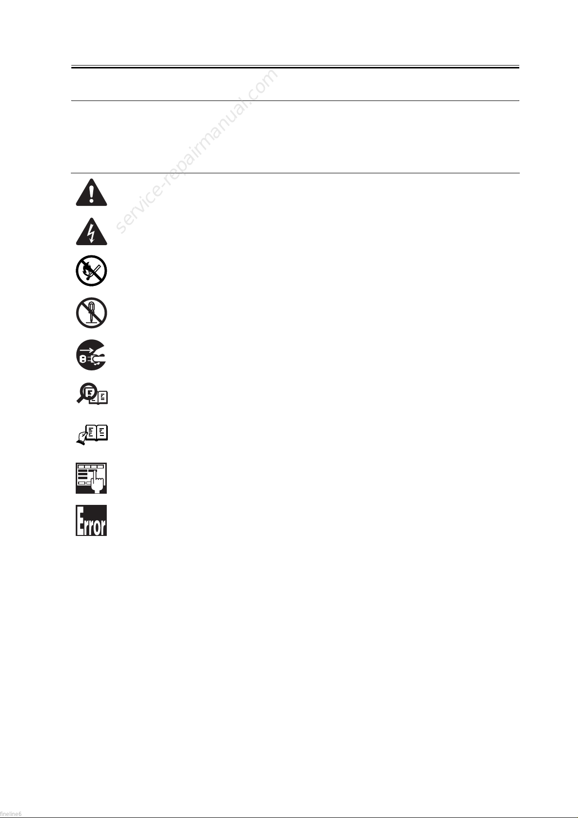
Symbols Used
Introducti
on
This do
cumentation uses the following symbols to indicate special information:
Symbol Description
cates an item of a non-specific nature, possibly classified as Note, Caution, or Warning.
Indi
Indicates an item requiring care to avoid electric shocks.
service-repairmanual.com
Indicates an item requiring care to avoid combustion (fire).
Indicates an item prohibiting disassembly to avoid electric shocks or problems.
Indicates an item requiring disconnection of the power plug from the electric outlet.
Indicates an item intended to provide notes assisting the understanding of the topic in question.
Memo
REF.
Indicates an item of reference assisting the understanding of the topic in question.
Provides a description of a service mode.
Provides a description of the nature of an error indication.
fineline6
Page 5

Introduction
The following
1. Each chapter contains sections explaining the purpose of specific functions and the relationship between electrical
and mechanical systems with reference to the timing of operation.
In the diagrams, represents the path of mechanical drive; where a signal name accompanies the symbol ,
the arrow indicates the direction of the electric signal.
The expression "turn on the power" means flipping on the power switch, closing the front door, and closing the
delivery unit door, which results in supplying the machine with power.
2. In the digital circuits, '1'is used to indicate that the voltage level of a given signal is "High", while '0' is used to
indicate "Low".(The voltage value, however, differs from circuit to circuit.) In addition, the asterisk (*) as in
"DRMD*" indicates that the DRMD signal goes on when '0'.
In practically all cases, the internal mechanisms of a microprocessor cannot be checked in the field. Therefore, the
operations of the microprocessors used in the machines are not discussed: they are explained in terms of from
sensors to the input of the DC controller PCB and from the output of the DC controller PCB to the loads.
The descriptions in this Service Manual are subject to change without notice for product improvement or other
purposes, and major changes will be communicated in the form of Service Information bulletins.
All service persons are expected to have a good understanding of the contents of this Service Manual and all relevant
Service Information bulletins and be able to identify and isolate faults in the machine."
rules apply throughout this Service Manual:
service-repairmanual.com
fineline6
Page 6

service-repairmanual.com
fineline6
Page 7

Contents
Contents
Chapter 1 Introduction
1.1 System Construction......
1.2 Product Specifications.....................................................................................................................................1- 15
service-repairmanual.com
1.1.1Overview of the System with a Delivery Accessory......................................... ..........................................1- 1
1.1.2Delivery Accessory System Configuration 1.............................................................................................. 1- 1
1.1.3Delivery Accessory System Configuration 2.............................................................................................. 1- 3
1.1.4Delivery Accessory System Configuration 3.............................................................................................. 1- 5
1.1.5Pickup/Original Handling Accessories System Configuration ...................................................................1- 6
1.1.6Reader Heater System Configuration..........................................................................................................1- 8
1.1.7Cassette Heater System Configuration 1.....................................................................................................1- 9
1.1.8Cassette Heater System Configuration 2...................................................................................................1- 10
1.1.9Side Deck Heater System Configuration...................................................................................................1- 11
1.1.10Printing/Transmitting Accessories System Configuration......................................................................1- 12
1.1.11List of Print Transmission Optional Functions ......................................................................................1- 13
1.2.1 Names of Parts........................................................................................................................ ..................1- 15
1.2.1.1 Names of Parts...................................................................................................................................1- 15
1.2.1.2 Cross Section......................................................................................................................... ............1- 16
1.2.2 Using the Machine.................................................................................................................................... 1- 19
1.2.2.1 Turning On the Power Switch...........................................................................................................1- 19
1.2.2.2 When Turning Off the Main Power Switch ......................................................................................1- 20
1.2.2.3 Control Panel................................................................................................................... ..................1- 22
1.2.3 User Mode Items....................................................................................................................................... 1- 23
1.2.3.1 Common Settings ..............................................................................................................................1- 23
1.2.3.2 Setting the Time .......................................................................................................................... ......1- 28
1.2.3.3 Adjustments and Cleaning.................................................................................................................1- 28
1.2.3.4 Report Output....................................................................................................................................1- 28
1.2.3.5 System Control Settings....................................................................................................................1- 29
1.2.3.6 Copy Settings .................................................................................................................................1- 32
1.2.3.7 Transmission/Reception Settings .................................................................................................1- 32
1.2.3.8 Box Settings.......................................................................................................................................1- 35
1.2.3.9 Printer Settings ..................................................................................................................................1- 35
1.2.3.10 Address Book Settings ....................................................................................................................1- 37
1.2.4 Maintenance by the User...........................................................................................................................1- 39
1.2.4.1 Cleaning................................................................................................................ .............................1- 39
1.2.4.2 Inspection .............................................................................................................................. ............1- 40
1.2.5 Safety ........................................................................................................................... .............................1- 42
1.2.5.1 Safety of the Laser Light...................................................................................................................1- 42
1.2.5.2 CDRH Regulations............................................................................................................................1- 42
1.2.5.3 Handling the Laser Unit ................................................ ....................................................................1- 43
1.2.5.4 Safety of Toner..................................................................................................................................1- 43
1.2.6 Product Specifications ..............................................................................................................................1- 44
1.2.6.1 Product Specifications.......................................................................................................................1- 44
1.2.7 Function List.............................................................................................................................................1- 46
....................................................................................................................................1- 1
fineline6
Page 8

Contents
1.2.7.1 Printing Speed....
1.2.7.2 Printing Speed....................................................................................................................................1- 48
1.2.7.3 Types of Paper...................................................................................................................................1- 49
Chapter 2 Installa
2.1 Making Pre-Checks .........
2.1.1Selecting the Site of Ins tallation .................................................................................................................2- 1
2.1.2Before Starting the Work (230V)................................................................................................................ 2 - 3
2.2 Unpacking and Installation................................................................................................................................2- 8
2.2.1Unpacking and Removin g the Packaging Materials....................................................................................2- 8
2.2.2Installing the Toner Bottle...........................................................................................................................2- 9
2.2.3Installing the Drum Unit....................................................................................................... . ..................2- 10
2.2.4Securing the Copier Main Unit........................................................................................ .. ....................2- 14
2.2.5Connecting the Cable................................................. ................................................ .. ............................2- 15
2.2.6Stirring Toner........................................................................................................ ... ................................2- 15
2.2.7Setting the Cassettes.............................. .............................................................. .................................... .2- 15
2.2.8APVC Correction of the Drum.................................................................. .. ...........................................2- 16
2.2.9Adjusting the Image Position................................................................ . . ................................................2- 17
2.2.10Attaching Other Parts ...................................................................... .......................................................2- 20
2.2.11If Not Connected to a Network................................................... ............................................................2- 21
2.3 Checking the Connection to the Network................................... . ...............................................................2- 23
2.3.1Overview.......................................................................... .. ......................................................................2- 23
2.3.2Using the PING Function ........................................... .. ............................................... ...........................2- 23
2.3.3Making a Check Using a Remote Host Address .......................................................................................2- 23
2.4 Troubleshooting the Network..........................................................................................................................2- 25
2.4.1Overview....................................................................................................................................................2- 25
2.4.2Making a Check Using a Loopback Address ............................................................................................2- 25
2.4.3Making a Check Using a Local Host Address...........................................................................................2- 25
2.5 Checking the Images/Operations................................................................................................................. ....2- 26
2.5.1Checking the Image Quality and Operation ..............................................................................................2- 26
2.6 Installing the Card Reader...............................................................................................................................2- 27
2.6.1Points to Note ............................................................................................................................. ...............2- 27
2.6.2Checking the Contents...............................................................................................................................2- 27
2.6.3Installation Procedure............................................................................................................................ ....2- 28
2.6.4Installation in a NetSpot Accountant (NSA) Environment ...................................................................... .2- 32
2.7 Installing the NE Controller.............................................................................................................................2- 33
2.7.1Installing the NE Controller-A1 ................................................................................................................2- 33
..................................................................................................... ...........................1- 46
tion
..................................................................................................................................2- 1
service-repairmanual.com
fineline6
Chapter 3 Basic Operation
3.1 Construction.
3.1.1Functional Construction...............................................................................................................................3- 1
3.1.2Major PCB Wiring diagram.........................................................................................................................3- 2
3.2 Basic Sequence..................................................................................................................................................3- 5
3.2.1Basic Sequence of Operation at Power-On .................................................................................................3- 5
......................................................................................................................................................3- 1
Chapter 4 Main Controller
Page 9

Contents
4.1 Construction ......
4.1.1Construction and Mechanisms ....................................................................................................................4- 1
4.2 Construction of the Electrical Circuitry ............................................................................................................4- 3
4.2.1Main Controller PCB...................................................................................................................................4- 3
4.2.2HDD ............................................................................................................................................................4- 4
4.3 Start-Up Sequence.............................................................................................................................................4- 7
4.3.1Overview .....................................................................................................................................................4- 7
4.3.2Start-Up Sequence.......................................................................................................................................4- 7
4.4 Shut-Down Sequence......................................................................................................................................4- 10
4.4.1Overview ...................................................................................................................................................4- 10
4.4.2Flow of Operation ............................................................................................................................ .........4- 10
4.5 Image Processing........................................................................................................................... ..................4- 11
4.5.1Overview of the Image Flow.....................................................................................................................4- 11
4.5.2Construction of the Image Processing Module ......................................................................................... 4- 11
4.5.3Reader Unit Input Image Processing.........................................................................................................4- 12
4.5.4Compressio/ Extesion/ Editing Block .................................. .................................................................... 4- 13
4.5.5Printer unit Output Image Processing .......................................................................................................4- 14
4.6 Flow of Image Data.........................................................................................................................................4- 15
4.6.1Flow of Image Data According to Copy Functions ................................. .................................................4- 15
4.6.2Flow of Image Data for the Box Function .............................. ..................................................................4- 15
4.6.3Flow of Image Data for the SEND Function.............................................................................................4- 16
4.6.4Flow of Image Data for the Fax Transmission..........................................................................................4- 17
4.6.5Flow of Image Data for the Fax Reception Function................................................................................ 4- 17
4.6.6Flow of Image Data for the PDL Function................................................................................................4- 18
4.7 Parts Replacement Procedure..........................................................................................................................4- 20
4.7.1 Main Controller PCB............................................................................................................................... .4- 20
4.7.1.1 Removing the Rear Cover.................................................................................................................4- 20
4.7.1.2 Removing the Main Controller PCB.................................................................................................4- 20
4.7.2 SDRAM ....................................................................................................................................................4- 21
4.7.2.1 Removing the Face Cover................................................................................................................. 4- 21
4.7.2.2 Removing the SDRAM .....................................................................................................................4- 21
4.7.3 Boot ROM.................................................................................................................................................4- 22
4.7.3.1 Removing the Face Cover................................................................................................................. 4- 22
4.7.3.2 Removing the Boot ROM..................................................................................................................4- 22
4.7.4 HDD..........................................................................................................................................................4- 22
4.7.4.1 Removing the Face Cover................................................................................................................. 4- 22
4.7.4.2 Removing the Counter PCB..............................................................................................................4- 23
4.7.4.3 Removing the HDD............................................................................................................ ...............4- 23
................................................................................................................................................4- 1
fineline6
Chapter 5 Original Exposure System
5.1 Construction ......
5.1.1Specifications, Control Mechanisms, and Functions ..................................................................................5- 1
5.1.2Major Components. .. ............................. ...................................................................................................5- 2
5.1.3Construction of the Control System............................................................................................................5- 4
5.1.4Reader Controller PCB................................................................................................................................5- 5
5.2 Basic Sequence..................................................................................................................................................5- 7
5.2.1Basic Sequence of Operation at Power-On.................................................................................................5- 7
5.2.2Basic Sequence of Operation in Response to a Press on the Start Key (book mode; 1 original) ............... 5- 7
....................... . .....................................................................................................................5- 1
service-repairmanual.com
Page 10

Content
s
5.2.3Basic Sequence
5.3 Various Control ............................................................................................................................. ..................5- 10
5.3.1 Controlling the Scanner Drive System......................................................................................................5- 10
5.3.1.1 Outline .......................................................................................................................... .....................5- 10
5.3.1.2 Controlling the Reader Motor................................. ...........................................................................5- 10
5.3.2 Contact Image Sensor (CIS)......................................................................................................................5- 12
5.3.2.1 Outline .......................................................................................................................... .....................5- 12
5.3.2.2 Analog Control Inside the Contact Image Sensor .............................................................................5- 13
5.3.3 Enlargement/Reduction.............................................................................................................................5- 14
5.3.3.1 Changing the Magnification in Main Scanning Direction.................................................................5- 14
5.3.3.2 Varying the Magnification in Sub Scanning Direction .....................................................................5- 14
5.3.4 Detecting the Size of Originals .................................................................................................................5- 16
5.3.4.1 Outline .......................................................................................................................... .....................5- 16
5.3.4.2 Outline of Size Identification...................................................... ..................................... ..................5- 17
5.3.5 Dirt Sensor Control ...................................................................................................................... .............5- 19
5.3.5.1 Outline .......................................................................................................................... .....................5- 19
5.3.6 Image Processing.......................................................................................................................................5- 22
5.3.6.1 Outline .......................................................................................................................... .....................5- 22
5.3.6.2 CCD Drive.........................................................................................................................................5- 23
5.3.6.3 Gain Correction and Offset Correction of the CCD Output..............................................................5- 23
5.3.6.4 A/D Conversion of the CCD Output........................................... .......................................................5- 24
5.3.6.5 Shading Correction (outline) .............................................................................................................5- 24
5.3.6.6 Shading Adjustment................................................ ....................................................................... ....5- 24
5.3.6.7 Shading Correction................................ ............................................................................................5- 24
5.4 Parts Replacement Procedure............................................................................................................. .............5- 26
5.4.1 Copyboard glass........................................................................................................................................5- 26
5.4.1.1 Removing the Copyboard Glass........................................................................................................5- 26
5.4.1.2 Removing the ADF Reading Glass....................................................................................................5- 26
5.4.2 Reader Controller PCB..............................................................................................................................5- 27
5.4.2.1 Before Replacing the Reader Controller PCB ...................................................................................5- 27
5.4.2.2 Removing the Reader Rear Cover.............................................................................................. .......5- 27
5.4.2.3 Removing the rear cover of the machine....................................................................................... ....5- 27
5.4.2.4 Removing the flexible cable cover ....................................................................................................5- 28
5.4.2.5 Removing the Copyboard Glass........................................................................................................5- 28
5.4.2.6 Removing the Reader Controller PCB...............................................................................................5- 29
5.4.2.7 After Replacing the Reader Controller PCB or After Initializing the RAM .....................................5- 31
5.4.3 Scanner Motor....................................................................................................................................... ....5- 32
5.4.3.1 Removing the Reader Rear Cover.............................................................................................. .......5- 32
5.4.3.2 Removing the Scanner Motor........................................................... .................................................5- 32
5.4.4 Contact sensor.................................................................................................................................... .......5- 33
5.4.4.1 Removing the Reader Front Cover....................................................................................................5- 33
5.4.4.2 Removing the Reader Rear Cover.............................................................................................. .......5- 33
5.4.4.3 Removing the Copyboard Glass........................................................................................................5- 34
5.4.4.4 Removing the Contact Image Sensor (CIS).............................................. .........................................5- 35
5.4.4.5 After Replacement of the CIS............................................................................................................5- 36
5.4.5 Copyboard Cover Open/Close Sensor.......................................................................................................5- 36
5.4.5.1 Removing the Reader Rear Cover.............................................................................................. .......5- 36
5.4.5.2 Removing the Copyboard Cover Open/Closed Sensor (front/rear)...................................................5- 37
5.4.6 Contact Sensor HP Sensor.........................................................................................................................5- 37
of Operation in Response to a Press on the Start Key (ADF mode; 1 original )...............5- 8
fineline6
service-repairmanual.com
Page 11

Contents
5.4.6.1 Removing the Copyboard Glass.....
5.4.6.2 Removing the ADF Reading Glass .......................................... .........................................................5- 38
5.4.6.3 Removing the Contract Sensor Home Position Sensor.....................................................................5- 39
5.4.7 Original Size Sensor .................................................................................................................................5- 39
5.4.7.1 Removing the Reader Rear Cover.....................................................................................................5- 39
5.4.7.2 Removing the Copyboard Glass........................................................................................................ 5- 40
5.4.7.3 Removing the Original Size Sensor .................................................................................................. 5- 41
5.4.8 Reader Heater (option)..............................................................................................................................5- 42
5.4.8.1 Removing the Copyboard Glass........................................................................................................ 5- 42
5.4.8.2 Removing the Reader Heater (right) .................................................................................................5- 43
5.4.8.3 Removing the ADF Reading Glass .......................................... .........................................................5- 43
5.4.8.4 Removing the Reader Heater (left)........................................................................................... .........5- 44
...................................................................................................5- 37
Chapter 6 Laser Exposure
6.1 Construction ......
6.1.1Specifications, Control Mechanism, and Functions....................................................................................6- 1
6.1.2Major Components.......................................................... ............................................................................6- 2
6.1.3Construction of the Control System............................................................................................................6- 2
6.2 Basic Sequence...................................................................................... ...........................................................6- 6
6.2.1Basic Sequence ................................... ......................................... . ............................................................6- 6
6.3 Various Controls........................................................................... ................................................................... 6- 7
6.3.1 Controlling the Laser Activation Timing......................... ... ......................................................................6- 7
6.3.1.1 Turning On and off the Laser Light ................... .. .............................................................................6- 7
6.3.1.2 Main Scanning Synchronous Control........... . . .................................................................................. 6- 8
6.3.2 Controlling the Intensity of Laser Light .......... ... ......................................................................................6- 9
6.3.2.1 APC Control....................................... . . ...........................................................................................6- 9
6.3.3 Controlling the Laser Scanner Motor .. ... ...............................................................................................6- 10
6.3.3.1 Controlling the Laser Scanner Motor................................................................................................6- 10
6.3.4 Controlling the Laser Shutter .... . . .................................................................................................... ......6- 10
6.3.4.1 Controlling the Laser Shutter........................................................................................................ .... 6- 10
6.4 Parts Replacement Procedure.. .....................................................................................................................6- 12
6.4.1 Laser Scanner Unit....................................................................................................................................6- 12
6.4.1.1 Removing the Front Cover Unit........................................................................................................6- 12
6.4.1.2 Removing the Left Cover..................................................................................................................6- 12
6.4.1.3 Removing the Laser Unit...................................................................................................................6- 12
................................................................................................................................................6- 1
service-repairmanual.com
fineline6
Chapter 7 Image Form
7.1 Construction ......
7.1.1Specifications of the Image Formation System...........................................................................................7- 1
7.1.2Major Components of the Image Formation System ..................................................................................7- 2
7.2 Image Formation Process..................................................................................................................................7- 4
7.2.1Image Formation Process (outline) ............................................................................................................. 7- 4
7.2.2Image Formation Process (image formation)..............................................................................................7- 5
7.3 Basic Sequence..................................................................................................................................................7- 6
7.3.1Sequence of Operation (initial rotation)......................................................................................................7- 6
7.3.2Sequence of Operation (initial rotation)......................................................................................................7- 6
7.3.3Sequence of Operation (copying)................................................................................................................7- 7
................................................................................................................................................7- 1
ation
Page 12

Contents
7.3.4Seq
7.3.5Sequence of Operation (last rotation)..........................................................................................................7- 8
7.3.6Sequence of Operation (last rotation)..........................................................................................................7- 9
7.4 Image Stabilization Control................................................................................................................ .............7- 10
7.4.1Overview....................................................................................................................................................7- 10
7.4.2APVC Control ...........................................................................................................................................7- 10
7.4.3ATVC Control...........................................................................................................................................7- 11
7.5 Drum Unit........................................................................................................................................................7- 12
7.5.1 Charging Mechanism ................................................................................................................................7- 12
7.6 Drum Cleaner Unit ..........................................................................................................................................7- 14
7.6.1Photosensitive Drum Cleaning................................................................................................ ..................7- 14
7.7 Developing Unit........................................................................................................................................... ....7- 15
7.7.1Controlling the Developing Bias.................................................................................................. .............7- 15
7.8 Toner Container.......................................................................................................................... .....................7- 16
7.8.1Overview....................................................................................................................................................7- 16
7.8.2Route of Toner Supply...............................................................................................................................7- 17
7.8.3Controlling the Drive of the Toner Cartridge............................................................................................7- 18
7.8.4Toner Supply Control............................................................................................................................ ....7- 19
7.8.5Recovery Sequence..................................................................................................................... ...............7- 19
7.8.6Toner Level Detection...............................................................................................................................7- 20
7.9 Transfer Unit...................................................................................................................... ..............................7- 21
7.9.1 Outline of the Transfer Unit.............................................................................................. ........................7- 21
7.9.2 Controlling the Transfer Bias....................................................................................................................7- 21
7.9.3 Cleaning ....................................................................................................................................................7- 22
7.9.4 Separation Mechanism....................................................................................................................... .......7- 22
7.10 Transfer Mechanism................... . . ................................................ ..................................... ........................7- 23
7.10.1 Transfer Guide Bias .......... .. ..................................................................................................................7- 23
7.11 Photosensitive Drum Cleaning ......................................................................................................................7- 24
7.11.1Outline ............. .. ................................................................................................................................... .7- 24
7.11.2Collection of Waste Toner.......................................................................................................................7- 24
7.11.3Checking the Waste Toner Box................................................ ...............................................................7- 24
7.12 Parts Replacement Procedure........................................................................................................................7- 26
7.12.1 Pre-Exposure Lamp .................................................................................................................................7- 26
7.12.2 Drum Unit ...............................................................................................................................................7- 31
uence of Operation (copying)................................................................................................................7- 8
7.5.1.1 Controlling the Primary Charging Bias .............................................................................................7- 12
7.5.1.2 Primary Charging Roller Cleaning Mechanism.................................................................................7- 12
7.9.1.1 Outline .......................................................................................................................... .....................7- 21
7.9.2.1 Transfer Roller Bias Control..............................................................................................................7- 21
7.9.3.1 Transfer Roller Cleaning Mechanism................................................................................................7- 22
7.9.4.1 Controlling the Static Eliminator Bias...............................................................................................7- 22
7.10.1.1 Transfer Guide Bias Control............................................................................................................7- 23
7.12.1.1 Removing the Front Cover Unit ......................................................................................................7- 26
7 12.1.2 Removing the Waste Toner Case................................................................................................. ....7- 26
7.12.1.3 Removing the Toner Cartridge........................................................................................................7- 26
service-repairmanual.com
7.12.1.4 Removing the Drum Unit ................................................................................................................7- 27
7.12.1.5 Removing the Developing Assembly..............................................................................................7- 28
7.12.1.6 Removing the Upper Tray ...............................................................................................................7- 30
7.12.1.7 Removing the Toner Cartridge Cover .............................................................................................7- 30
7.12.1.8 Removing the Pre-Exposure Lamp..................................................................................................7- 30
fineline6
Page 13

Contents
7.12.2.1 Removing the Front Cover Unit.....
7.12.2.2 Removing the Waste Toner Case........................................................................................... .........7- 31
7.12.2.3 Removing the Drum Unit................................................................................................................7- 32
7.12.3 Hopper Assembly............................................................................................................. .......................7- 33
7.12.3.1 Removing the Front Cover Unit......................................................................................................7- 33
7.12.3.2 Removing the Waste Toner Case........................................................................................... .........7- 33
7.12.3.3 Removing the Toner Cartridge........................................................................................................ 7- 34
7.12.3.4 Removing the Drum Unit................................................................................................................7- 34
7.12.3.5 Removing the Developing Assembly..............................................................................................7- 35
7.12.3.6 Removing the Upper Tray...............................................................................................................7- 37
7.12.3.7 Removing the Toner Cartridge Cover............................................................................................. 7- 37
7.12.3.8 Removing the Pre-Exposure Lamp .................................................................................................7- 37
7.12.3.9 Removing the Left Cover................................................................................................................7- 38
7.12.3.10 Removing the Laser Unit.............................................................................................................. .7- 38
7.12.3.11 Removing the Hopper Assembly............................................................................................... .... 7- 39
7.12.4 Sub Hopper ......................................................................................................................... ....................7- 40
7.12.4.1 Removing the Front Cover Unit......................................................................................................7- 40
7.12.4.2 Removing the Waste Toner Case........................................................................................... .........7- 40
7.12.4.3 Removing the Toner Cartridge........................................................................................................ 7- 41
7.12.4.4 Removing the Drum Unit................................................................................................................7- 42
7.12.4.5 Removing the Developing Assembly..............................................................................................7- 43
7.12.4.6 Removing the Upper Tray...............................................................................................................7- 44
7.12.4.7 Removing the Toner Cartridge Cover............................................................................................. 7- 44
7.12.4.8 Removing the Pre-Exposure Lamp .................................................................................................7- 45
7.12.4.9 Removing the Left Cover................................................................................................................7- 45
7.12.4.10 Removing the Laser Unit.............................................................................................................. .7- 45
7.12.4.11 Removing the Hopper Assembly............................................................................................... .... 7- 46
7.12.4.12 Removing the Toner Feedscrew Motor.........................................................................................7- 47
7.12.4.13 Removing the Sub Hopper ............................................................................................................7- 48
7.12.5 Developing Assembly.............................................................................................................................7- 49
7.12.5.1 Removing the Front Cover Unit......................................................................................................7 49
7.12.5.2 Removing the Waste Toner Case........................................................................................... .........7- 50
7.12.5.3 Removing the Developing Assembly......................................................................................... .... 7- 50
7.12.6 Developing Cylinder................................................................................................................... ... .......7- 52
7.12.6.1 Removing the Developing Cylinder................................................................................ . ............. 7- 52
7.12.7 Transfer Charging Roller.................................................................................................... ................... 7- 54
7.12.7.1 Removing the Transfer Roller.............................................................................. . . ......................7- 54
7.12.8 Waste Toner Box ................................................................................................... . . ............................7- 55
7.12.8.1 Removing the Front Cover Unit................................................................ . ...................................7- 55
7.12.8.2 Removing the Waste Toner Case........................................................ . .......................................7- 55
7.12.9 Toner Level Sensor..................................................................................... ...........................................7- 56
7.12.9.1 Removing the Front Cover Unit......................................................................................................7- 56
7.12.9.2 Removing the Waste Toner Case........................................................................................... .........7- 56
7.12.9.3 Removing the Toner Cartridge........................................................................................................ 7- 57
7.12.9.4 Removing the Drum Unit................................................................................................................7- 57
7.12.9.5 Removing the Developing Assembly..............................................................................................7- 58
7.12.9.6 Removing the Upper Tray...............................................................................................................7- 60
7.12.9.7 Removing the Toner Cartridge Cover............................................................................................. 7- 60
7.12.9.8 Removing the Pre-Exposure Lamp .................................................................................................7- 60
.................................................................................................7- 31
service-repairmanual.com
fineline6
Page 14

Contents
7.12.9.9 Removing the Left Cover ......
7.12.9.10 Removing the Laser Unit...............................................................................................................7- 61
7.12.9.11 Removing the Hopper Assembly ............................................................................................... ....7- 62
7.12.9.12 Removing the Toner Level Sensor................................................................................................7- 63
7.12.10 Toner Feedscrew Motor .......................................................................................................................7- 63
7.12.10.1 Removing the Front Cover Unit....................................................................................................7- 63
7.12.10.2 Removing the Waste Toner Case...................................................................................................7- 64
7.12.10.3 Removing the Toner Cartridge......................................................................................................7- 64
7.12.10.4 Removing the Drum Unit ..............................................................................................................7- 65
7.12.10.5 Removing the Developing Assembly............................................................................................7- 66
7.12.10.6 Removing the Upper Tray.............................................................................................................7- 67
7.12.10.7 Removing the Toner Cartridge Cover ...........................................................................................7- 68
7.12.10.8 Removing the Pre-Exposure Lamp................................................................................................7- 68
7.12.10.9 Removing the Left Cover ..............................................................................................................7- 68
7.12.10.10 Removing the Laser Unit...................................................................................................... .......7- 69
7.12.10.11 Removing the Hopper Assembly.................................................................................................7- 70
7.12.10.12 Removing the Toner Feedscrew Motor .......................................................................................7- 71
7.12.11 Static Charge Eliminator.......................................................................................................................7- 71
7.12.11.1 Removing the Static Eliminator.............................................................................................. .......7- 71
...................................................................................................... ....7- 61
Chapter 8 Pickup/Feeding System
8.1 Construction.
8.1.1Specifications, Controls, and Functions......................................................................................................8- 1
8.1.2Division into Blocks....................................................................................................................................8- 2
8.1.3Division into Blocks....................................................................................................................................8- 3
8.1.4Arrangement of Rollers ...............................................................................................................................8 - 4
8.1.5Arrangement of Rollers ...............................................................................................................................8 - 5
8.1.6Diagram of Paper Paths (printer on its own)...............................................................................................8- 6
8.1.7Diagram of Paper Paths (w/ copy tray ).......................................................................................................8- 7
8.1.8Diagram of Paper Paths (w/ 3 Way Unit-A1 /copy tray).............................................................................8- 8
8.1.9Diagram of Paper Paths (w/ Finisher-S1/copy tray)....................................................................................8- 9
8.1.10Diagram of Paper Paths (w/ Finisher-Q3/Saddle Finisher-Q4)...............................................................8- 10
8.1.11Arrangement of Sensors ..................................................................................................... .....................8- 11
8.1.12Arrangement of Sensors ..................................................................................................... .....................8- 12
8.1.13Route of Drive .........................................................................................................................................8- 14
8.1.14Route of Drive .........................................................................................................................................8- 14
8.2 Basic Sequence........................................................................................................................... .....................8- 17
8.2.1Basic Sequence .........................................................................................................................................8- 17
8.2.2Increase in Speed.......................................................................................................................................8- 17
8.2.3Increase in Speed.......................................................................................................................................8- 20
8.3 Detecting Jams.................................................................................................................................................8- 23
8.3.1 Delivery Jams........................................................................................................................................ ...8- 23
8.3.1.1 Delay Jam Outside the Cassette Pickup Assembly.................................................................... .. ....8- 23
8.3.1.2 Delay Jam in the Cassette Pickup Assembly........................................................................ ............8- 23
8.3.2 Stationary Jams ...................................................................................................................... ... ..............8- 24
8.3.2.1 Common Stationary Jam.................................................. .......................................... . ....................8- 24
8.3.2.2 Stationary Jam at Power-On............................................................................... ... ..........................8- 25
8.3.3 Other Jams............................................................................................................. ... ...............................8- 25
......................................................................................................................................................8- 1
fineline6
service-repairmanual.com
Page 15

Contents
8.3.3.1 Door Open Jam.....
8.4 Cassette Pick-Up Unit.....................................................................................................................................8- 26
8.4.1Overview ...................................................................................................................................................8- 26
8.4.2Basic Sequence ................................... ......................................................................................................8- 27
8.4.3Identifying the Paper Size .........................................................................................................................8- 27
8.4.4Setting Up the Universal Cassette.............................................................................................................8- 29
8.4.5Paper Level Sensor....................................................................................................................................8- 30
8.5 Manual Feed Pickup Unit................................................................................................................................8- 34
8.5.1Overview ...................................................................................................................................................8- 34
8.5.2Basic Sequence of Operation ............................... ................................................................... ..................8- 35
8.5.3Identifying the Paper Size .........................................................................................................................8- 35
8.5.4Paper Retaining Mechanism......................................................................................................................8- 36
8.6 Registration Unit ...................................................................................................................... .......................8- 38
8.6.1Overview ...................................................................................................................................................8- 38
8.6.2Checking Horizontal Registration.............................................................................................................8- 38
8.7 Duplex Feeding Unit.......................................................................................................................................8- 40
8.7.1Overview ...................................................................................................................................................8- 40
8.7.2Overview ...................................................................................................................................................8- 41
8.7.3Sequence of Image Formation...................................................................................................................8- 42
8.7.4Sequence of Image Formation...................................................................................................................8- 44
8.7.5Flow of Paper (w/o/ delivery option) ........................................................................................................8- 45
8.7.6Flow of Paper (w/ delivery option) ......................................................................................... ..................8- 51
8.7.7Flow of Paper ................................................................................................................. ..........................8- 57
8.8 Parts Replacement Procedure..........................................................................................................................8- 64
8.8.1 Pick-up Unit 1..................................................................................................................................... ......8- 64
8.8.1.1 Removing the Right Cover (rear)......................................................................................................8- 64
8.8.1.2 Removing the Right Door .................................................................................................................8- 64
8.8.1.3 Removing the Right Door .................................................................................................................8- 65
8.8.1.4 Removing the Right Cover (lower front) ......................................................................................... .8- 66
8.8.1.5 Removing the Pickup Assembly 1 .................................................................................................... 8- 66
8.8.2 Pick-up Unit 2..................................................................................................................................... ......8- 67
8.8.2.1 Removing the Right Cover (rear)......................................................................................................8- 67
8.8.2.2 Removing the Right Cover (lower front) ......................................................................................... .8- 67
8.8.2.3 Removing the Pickup Assembly 2 .................................................................................................... 8- 67
8.8.3 Pickup Roller ............................................................................................................................................8- 68
8.8.3.1 Removing the Pickup Roller/Feed Roller/Separation Roller ............................................................ 8- 68
8.8.4 Sensor Mount............................................................................................................................................8- 68
8.8.4.1 Removing the Right Cover (rear)......................................................................................................8- 68
8.8.4.2 Removing the Right Door .................................................................................................................8- 68
8.8.4.3 Removing the Right Door .................................................................................................................8- 70
8.8.4.4 Removing the Right Cover (lower front) ......................................................................................... .8- 70
8.8.4.5 Removing the Pickup Assembly 1 .................................................................................................... 8- 71
8.8.4.6 Removing the Pickup Assembly 2 .................................................................................................... 8- 71
8.8.4.7 Removing the Sensor Mounting Plate...............................................................................................8- 71
8.8.4.8 Mounting the Sensor Mounting Plate................................................................................................8- 72
8.8.5 Cassette Pick-up Motor 1 ..........................................................................................................................8- 73
8.8.5.1 Removing the Rear Cover.................................................................................................................8- 73
8.8.5.2 Removing the Right Cover (rear)......................................................................................................8- 73
8.8.5.3 Removing the Pickup Motor Base.....................................................................................................8- 74
......................................................................................................... ....................8- 25
service-repairmanual.com
fineline6
Page 16

Contents
8.8.5.4 Removing the Cassette Pickup Motor
8.8.6 Cassette Pick-up Motor 2............................ ..............................................................................................8- 74
8.8.6.1 Removing the Rear Cover................................................................................................................. .8- 74
8.8.6.2 Removing the Right Cover (rear) ......................................................................................................8- 75
8.8.6.3 Removing the Pickup Motor Base.....................................................................................................8- 75
8.8.6.4 Removing the Cassette Pickup Motor 2 .............................................................. ..............................8- 76
8.8.7 Cassette Size Sensor ..................................................................................................................................8- 76
8.8.7.1 Removing the Right Cover (rear) ......................................................................................................8- 76
8.8.7.2 Removing the Right Door.................................. ................................................................................8- 77
8.8.7.3 Removing the Right Door.................................. ................................................................................8- 78
8.8.7.4 Removing the Right Cover (lower front)...........................................................................................8- 78
8.8.7.5 Removing the Pickup Assembly 2.....................................................................................................8- 79
8.8.7.6 Removing the Pickup Assembly 1.................................................................... . ..............................8- 79
8.8.7.7 Removing the Cassette Size Sensor.............................. .............................. ... .................................8- 79
8.8.8 Cassette Retry Paper Sensor.......................................................................... .. ........................................8- 80
8.8.8.1 Removing the Right Cover (rear) ..................................................... ... ............................................8- 80
8.8.8.2 Removing the Right Door.................................. ......................... .. . .................................................8- 81
8.8.8.3 Removing the Right Door.................................. .................... .. .......................................................8- 82
8.8.8.4 Removing the Right Cover (lower front).......................... . . ............................................................8- 83
8.8.8.5 Removing the Pickup Assembly 1.............................. .. . .................................................................8- 83
8.8.8.6 Removing the Pickup Assembly 2............................ ........................................................................8- 84
8.8.8.7 Removing the Sensor Mounting Plate.............. . .......................................................................... .8- 84
8.8.8.8 Removing the Cassette Retry Paper Sensor . ..................................................................................8- 85
8.8.9 Cassette Paper Sensor..................................... .. ................................................... .................................. .8- 85
8.8.9.1 Removing the Right Cover (rear) ......................................................................................................8- 85
8.8.9.2 Removing the Right Door.................................. ................................................................................8- 85
8.8.9.3 Removing the Right Door.................................. ................................................................................8- 86
8.8.9.4 Removing the Right Cover (lower front)...........................................................................................8- 87
8.8.9.5 Removing the Pickup Assembly 1.....................................................................................................8- 88
8.8.9.6 Removing the Pickup Assembly 2.....................................................................................................8- 88
8.8.9.7 Removing the Sensor Mounting Plate...............................................................................................8- 88
8.8.9.8 Removing the Cassette Paper Sensor.................................................................................................8- 89
8.8.10 Cassette Paper Level Sensor (A/B).........................................................................................................8- 89
8.8.10.1 Removing the Right Cover (rear) ....................................................................................................8- 89
8.8.10.2 Removing the Right Door................................................................................................................8- 90
8.8.10.3 Removing the Right Door................................................................................................................8- 91
8.8.10.4 Removing the Right Cover (lower front).........................................................................................8- 92
8.8.10.5 Removing the Pickup Assembly 1...................................................................................................8- 92
8.8.10.6 Removing the Pickup Assembly 2...................................................................................................8- 93
8.8.10.7 Removing the Sensor Mounting Plate .............................................................................................8- 93
8.8.10.8 Removing the Cassette Paper Level Sensor (A/B)..........................................................................8- 94
8.8.11 Slide Resistor...........................................................................................................................................8- 94
8.8.11.1 Removing the Right Cover (rear) ....................................................................................................8- 94
8.8.11.2 Removing the Right Door................................................................................................................8- 94
8.8.11.3 Removing the Right Door................................................................................................................8- 95
8.8.11.4 Removing the Manual Feed Unit.....................................................................................................8- 96
8.8.11.5 Removing the Manual Tray Unit.....................................................................................................8- 97
8.8.11.6 Removing the Slide Resistor.................................................................................................. ..........8- 98
8.8.12 Cassette Pickup Solenoid ........................................................................................................... .............8- 98
1 ......................................................... ...................................8- 74
service-repairmanual.com
fineline6
Page 17

Contents
8.8.12.1 Removing the Right Cover (rear)......
8.8.12.2 Removing the Right Door ...............................................................................................................8- 98
8.8.12.3 Removing the Right Door ...............................................................................................................8- 99
8.8.12.4 Removing the Right Cover (lower front) ......................................................................................8- 100
8.8.12.5 Removing the Pickup Assembly 1 ................................................................................................8- 101
8.8.12.6 Removing the Pickup Assembly 2 ................................................................................................8- 101
8.8.12.7 Removing the Cassette Pickup Solenoid....................................................................................... 8- 101
8.8.13 Cassette Size Sensor Relay PCB........................................................................................................... 8- 102
8.8.13.1 Removing the Right Cover (rear)..................................................................................................8- 102
8.8.13.2 Removing the Right Door .............................................................................................................8- 102
8.8.13.3 Removing the Right Door .............................................................................................................8- 103
8.8.13.4 Removing the Right Cover (lower front) ......................................................................................8- 104
8.8.13.5 Removing the Pickup Assembly 1 ................................................................................................8- 104
8.8.13.6 Removing the Pickup Assembly 2 ................................................................................................8- 105
8.8.13.7 Removing the Cassette Size Sensor Relay PCB............................................................................8- 105
8.8.14 Manual Tray Assembly.........................................................................................................................8- 105
8.8.14.1 Removing the Right Cover (rear)..................................................................................................8- 105
8.8.14.2 Removing the Right Door .............................................................................................................8- 106
8.8.14.3 Removing the Right Door .............................................................................................................8- 107
8.8.14.4 Removing the Manual Feed Unit ..................................................................................................8- 108
8.8.14.5 Removing the Manual Feed Tray Assembly.................................................................................8- 109
8.8.15 Manual Feed Unit .................................................................................................................................8- 109
8.8.15.1 Removing the Right Cover (rear)..................................................................................................8- 109
8.8.15.2 Removing the Right Door .............................................................................................................8- 109
8.8.15.3 Removing the Right Door .............................................................................................................8- 111
8.8.15.4 Removing the Manual Feed Unit ......................................................................................... ....... 8- 111
8.8.16 Manual Pickup Roller ............................................................................................................. . . ......... 8- 112
8.8.16.1 Removing the Right Cover (rear)............................................................................ .... .. ............. 8- 112
8.8.16.2 Removing the Right Door ....................................................................................... . ...................8- 113
8.8.16.3 Removing the Right Door ............................................................................... .. ..........................8- 114
8.8.16.4 Removing the Manual Feed Unit .................................................................. . .............................8- 115
8.8.16.5 Removing the Manual Feed Pickup Roller .......................................... . ......................................8- 116
8.8.17 Manual Pick-up Clutch ........................................................................... . . ...................................... ..8- 116
8.8.17.1 Removing the Right Cover (rear)................................................ . .. ...........................................8- 116
8.8.17.2 Removing the Right Door .................................................... . ......................................................8- 116
8.8.17.3 Removing the Right Door ................................................ . ........................................................8- 118
8.8.17.4 Removing the Rear Cover............................................ ................................................................8- 118
8.8.17.5 Removing the Main Power Switch........................ ......................................................................8- 119
8.8.17.6 Removing the Manual Feed Pickup Clutch ...................................................................................8- 119
8.8.18 Manual Separation Pad ............................................................................................................... ..........8- 120
8.8.18.1 Removing the Right Cover (rear)..................................................................................................8- 120
8.8.18.2 Removing the Right Door .............................................................................................................8- 120
8.8.18.3 Removing the Right Door .............................................................................................................8- 121
8.8.18.4 Removing the Manual Feed Unit ..................................................................................................8- 122
8.8.18.5 Removing the Manual Feed Pickup Roller ...................................................................................8- 123
8.8.18.6 Removing the Manual Feed Separation pad..................................................................................8- 124
8.8.19 Registration Clutch ...............................................................................................................................8- 124
8.8.19.1 Removing the Rear Cover.............................................................................................................8- 124
8.8.19.2 Removing the Main Drive Assembly............................................................................................8- 124
..............................................................................................8- 98
service-repairmanual.com
fineline6
Page 18

Contents
8.8.19.3 Removing the Main Drive Assembly .....
8.8.19.4 Removing the Registration Clutch.................................................................................................8- 126
8.8.20 Feeding Roller.......................................................................................................................................8- 126
8.8.20.1 Removing the Pickup Roller/Feed Roller/Separation Roller.........................................................8- 126
8.8.21 Vertical Path Roller...............................................................................................................................8- 126
8.8.21.1 Removing the Right Cover (rear) ..................................................................................................8- 126
8.8.21.2 Removing the Right Door..............................................................................................................8- 127
8.8.21.3 Removing the Right Door..............................................................................................................8- 128
8.8.21.4 Removing the Right Cover (lower front).......................................................................................8- 129
8.8.21.5 Removing the Pickup Assembly 1.................................................................................................8- 129
8.8.21.6 Removing the Pickup Assembly 2.................................................................................................8- 130
8.8.21.7 Removing the Sensor Mounting Plate ...........................................................................................8- 130
8.8.21.8 Removing the Vertical Path Roller................................................................................................8- 131
8.8.22 Duplex Feed Roller 2 ............................................................................................................................8- 131
8.8.22.1 Removing the Right Cover (rear) ..................................................................................................8- 131
8.8.22.2 Removing the Right Door..............................................................................................................8- 131
8.8.22.3 Removing the Right Door..............................................................................................................8- 132
8.8.22.4 Removing the Duplex Feed Roller 2.............................................................................................8- 133
8.8.23 Duplex Feed Sensor ..............................................................................................................................8- 134
8.8.23.1 Removing the Right Cover (rear) ..................................................................................................8- 134
8.8.23.2 Removing the Right Door..............................................................................................................8- 134
8.8.23.3 Removing the Right Door..............................................................................................................8- 135
8.8.23.4 Removing the Duplex Feed Sensor ...............................................................................................8- 136
8.8.24 Duplex Feed Clutch...............................................................................................................................8- 137
8.8.24.1 Removing the Rear Cover..............................................................................................................8- 137
8.8.24.2 Removing the Duplex Feed Clutch................................................................................................ 8- 137
8.8.25 Delivery Assembly 1................................................. ............................................................................8- 138
8.8.25.1 Removing the Right Cover (rear) ..................................................................................................8- 138
8.8.25.2 Removing the Front Cover Unit ....................................................................................................8- 138
8.8.25.3 Removing the Delivery Tray .........................................................................................................8- 138
8.8.25.4 Removing the Right Door..............................................................................................................8- 139
8.8.25.5 Removing the Right Door..............................................................................................................8- 140
8.8.25.6 Removing the Extension Delivery Kit............................................... . .........................................8- 140
8.8.25.7 Removing the Delivery Assembly 1............................................. .. ...........................................8- 141
8.8.26 Fixing/ Delivery Drive Assembly .................................................. .. ...................................................8- 142
8.8.26.1 Removing the Right Cover (rear) ...................................... .. .......................................................8- 142
8.8.26.2 Removing the Front Cover Unit ................................... . . ............................................................8- 142
8.8.26.3 Removing the Delivery Tray ................................... .. ..................................................................8- 142
8.8.26.4 Removing the Right Door.................................. . . ......................................................................8- 143
8.8.26.5 Removing the Right Door............................... ..............................................................................8- 144
8.8.26.6 Removing the Delivery Assembly 1.......... ...................................................................................8- 144
8.8.26.7 Removing the Fixing Unit ................. ... ......................................................................................8- 145
8.8.26.8 Removing the Fixing/Delivery Drive Assembly ...........................................................................8- 146
8.8.27 Separation Roller............................. . . .................................................................................................8- 147
8.8.27.1 Removing the Pickup Roller/Feed Roller/Separation Roller.........................................................8- 147
service-repairmanual.com
.......................................................................................8- 125
fineline6
Chapter 9 Fixing System
9.1 Construction.
......................................................................................................................................................9- 1
Page 19

Contents
9.1.1Specifications, Control Mechanisms, and Functions
9.1.2Major Components.......................................................... ............................................................................9- 1
9.2 Basic Sequence..................................................................................................................................................9- 3
9.2.1Power-On Sequence ....................................................................................................................................9- 3
9.2.2Down Sequence...........................................................................................................................................9- 3
9.3 Various Control Mechanisms............................................................................................................................9- 4
9.3.1 Controlling the Speed of the Fixing Film ..................................................................................................9- 4
9.3.1.1 Controlling the Fixing Film Speed in Response to Low Temperature................................................9- 4
9.3.1.2 Controlling the Fixing Film Speed......................................................................................................9- 4
9.3.2 Controlling the Fixing Film Temperature................................................................................................... 9- 5
9.3.2.1 Controlling the Power Supply in Response to Low Temperature. ...................................................... 9- 5
9.3.2.2 Controlling the Feeding in Response to Low Temperature.................................................................9- 5
9.3.2.3 Controlling the Power Supply at Start-Up...........................................................................................9- 5
9.3.2.4 Copying Temperature Control.............................................................................................................9- 6
9.3.2.5 Changing the Fixing Film Control Temperature.................................................................................9- 6
9.3.2.6 Temperature Control in Response to Automatic Double-Sided Copy................................................9- 6
9.3.2.7 Temperature Control in Response to Change of Paper Size ...............................................................9- 7
9.3.3 Cleaning......................................................................................................................................................9- 7
9.3.3.1 Fixing Film Cleaning...........................................................................................................................9- 7
9.3.4 Detecting the Passage of Paper...................................................................................................................9- 8
9.3.4.1 Detecting the Passage of Paper............................................................................................................9- 8
9.4 Protective Functions..........................................................................................................................................9- 9
9.4.1Protective Functions....................................................................................................................................9- 9
9.4.2Detecting an Error .....................................................................................................................................9- 10
9.5 Parts Replacement Procedure..........................................................................................................................9- 12
9.5.1 Fixing Unit................................................................................................................................. ...............9- 12
9.5.1.1 Removing the Right Cover (rear)......................................................................................................9- 12
9.5.1.2 Removing the Right Door .................................................................................................................9- 12
9.5.1.3 Removing the Right Door .................................................................................................................9- 13
9.5.1.4 Removing the Fixing Unit................................................................................................................ .9- 14
9.5.2 Pressure Roller.............................................................................................................................. ............9- 15
9.5.2.1 Removing the Inside Delivery Cover Unit........................................................................................9- 15
9.5.2.2 Removing the Grounding Plate....................................................................................................... . 9- 16
9.5.2.3 Removing the Fixing Film Cover.............................................................................................. . .. .. 9- 16
9.5.2.4 Removing the Left Side Plate............................................................................................... ...........9- 17
9.5.2.5 Releasing the Locking Plate......................................................................................... . ... .............9- 18
9.5.2.6 Removing the Fixing Film Unit ................................................................................... . ..................9- 18
9.5.2.7 Removing the Inlet Guide .................................................................................... . . . .....................9- 19
9.5.2.8 Removing the Pressure Roller........................................................................ ...............................9- 20
9.5.3 Cleaning Roller................................................................................................. . .. .................................. 9- 21
9.5.3.1 Removing the Inside Delivery Cover Unit............................................ ...........................................9- 21
9.5.3.2 Removing the Cleaning Roller.......................................................... ...............................................9- 21
9.5.4 Fixing Film............................................................................................................................................... .9- 22
9.5.4.1 Removing the Inside Delivery Cover Unit........................................................................................9- 22
9.5.4.2 Removing the Grounding Plate.........................................................................................................9- 22
9.5.4.3 Removing the Fixing Film Cover......................................................................................................9- 22
9.5.4.4 Removing the Left Side Plate............................................................................................................9- 23
9.5.4.5 Releasing the Locking Plate..............................................................................................................9- 24
9.5.4.6 Removing the Fixing Film Unit ........................................................................................................9- 25
..................................................................................9- 1
service-repairmanual.com
fineline6
Page 20

Contents
9.5.5 Internal Delivery Sensor....
9.5.5.1 Removing the Inside Delivery Cover Unit ........................................................................................9- 26
9.5.5.2 Removing the Grounding Plate..........................................................................................................9- 26
9.5.5.3 Removing the Fixing Film Cover ......................................................................................................9- 27
9.5.5.4 Removing the Left Side Plate............................................................................................................9- 27
9.5.5.5 Releasing the Locking Plate ..............................................................................................................9- 28
9.5.5.6 Removing the Fixing Film Unit.........................................................................................................9- 29
9.5.5.7 Removing the Inside Delivery Sensor...............................................................................................9- 30
9.5.6 Fixing Film Sensor....................................................................................................................................9- 31
9.5.6.1 Removing the Inside Delivery Cover Unit ........................................................................................9- 31
9.5.6.2 Removing the Grounding Plate..........................................................................................................9- 31
9.5.6.3 Removing the Fixing Film Sensor................................................... .................................................9- 31
......................................................................................................... ...............9- 26
Chapter 10 External and Controls
10.1 Control Panel
10.1.1Overview..................................................................... . ..........................................................................10- 1
10.1.2LCD Indication Processing................................... .. ..............................................................................10- 1
10.1.3Adjustment of the LCD Contact....................... ......................................................................................10- 2
10.1.4Functions of the Control Panel CPU ........... ...........................................................................................10- 2
10.2 Counters.......................................... ............ . . ................................ .............................................................10- 3
10.2.1Overview............................................ .. ..................................................................................................10- 3
10.2.2Timing of Increasing the Count.. . ..........................................................................................................10- 4
10.3 Fans............................................................ ....................................................................................................10- 6
10.3.1Overview..................................................................................................................................................10- 6
10.3.22-Speed Control............................................................ ...........................................................................10- 6
10.3.3Sequence of Operation.............................................................................................................................10- 7
10.4 Power Supply System....................................................................................................................................10- 8
10.4.1 Power Supply .......................................................................................................................................... 10- 8
10.4.1.1 Route of Power Inside the Printer Unit ..........................................................................................10- 8
10.4.1.2 Power Supply Route in the Reader Unit..........................................................................................10- 9
10.4.1.3 Timing of Supply to the Reader Unit.............................................................................................10- 10
10.4.1.4 Connections to Various Accessories..............................................................................................10- 10
10.4.2 Rated Output of the DC Power Supply PCB....................................................................................... ..10- 11
10.4.2.1 Rated Output of the Printer Unit Power Supply PCB....................................................................10- 11
10.4.2.2 Rated Output of the Controller Power Supply PCB ......................................................................10- 12
10.4.2.3 Rated Output of the Accessories Power Supply PCB....................................................................10- 12
10.4.2.4 Rated Output of the All-Night Power Supply PCB.......................................................................10- 13
10.4.3 Protection Function ...................................................................................................... .........................10- 13
10.4.3.1 Protective Mechanisms..................................................................................................................10- 13
10.4.4 Backup Battery......................................................................................................................................10- 13
10.4.4.1 Backup Battery ..............................................................................................................................10- 13
10.4.5 Energy-Saving Function........................................................................................................................10- 14
10.4.5.1 Overview........................................................................................................................................10- 14
10.4.5.2 Machine as Supplied with Power...................................................................................................10- 15
10.5 Parts Replacement Procedure......................................................................................................................10- 17
10.5.1 Main Drive Assembly ........................................................ ...................................................................10- 17
10.5.1.1 Removing the Rear Cover..............................................................................................................10- 17
10.5.1.2 Removing the Main Drive Assembly ............................................................................................10- 17
......................................................................... .. ...................................................................10- 1
service-repairmanual.com
fineline6
Page 21

Contents
10.5.1.3 Removing the Main Drive Assembly...
10.5.2 Power Supply Unit...................................................................................................................... ..........10- 18
10.5.2.1 Removing the Rear Cover.............................................................................................................10- 18
10.5.2.2 Removing the Left Cover (lower) .................................................................................................10- 19
10.5.2.3 Removing the Accessories Power Supply PCB ............................................................................10- 19
10.5.2.4 Removing the Main Power Supply................................................................................................10- 20
10.5.3 Control Panel ...................................................................................................................................... ..10- 21
10.5.3.1 Removing the Control Panel .........................................................................................................10- 21
10.5.4 Control Panel LCD Unit ..................................................................................................................... ..10- 22
10.5.4.1 Removing the Control Panel .........................................................................................................10- 22
10.5.4.2 Removing the Control Panel Base Cover......................................................................................10- 23
10.5.4.3 Removing the Control Panel Inside Frame ...................................................................................10- 23
10.5.4.4 Removing the Control Panel LCD ................................................................................................10- 24
10.5.5 Removing the DC Controller PCB .......................................................................................................10- 24
10.5.5.1 Removing the Rear Cover.............................................................................................................10- 24
10.5.5.2 Removing the DC Controller PCB................................................................................................10- 24
10.5.6 Control Panel Inverter PCB........................................................................................................... .......10- 25
10.5.6.1 Removing the Control Panel .........................................................................................................10- 25
10.5.6.2 Removing the Control Panel Base Cover......................................................................................10- 26
10.5.6.3 Removing the Control Panel Inverter PCB...................................................................................10- 26
10.5.7 Control Panel Key Switch PCB.................................................................................................. ..........10- 26
10.5.7.1 Removing the Control Panel .........................................................................................................10- 26
10.5.7.2 Removing the Control Panel Base Cover......................................................................................10- 27
10.5.7.3 Removing the Control Panel Frame.......................................................................................... .... 10- 28
10.5.7.4 Removing the Control Panel Key Switch PCB.............................................................................10- 28
10.5.8 Control Panel CPU PCB.......................................................................................................................10- 29
10.5.8.1 Removing the Control Panel .........................................................................................................10- 29
10.5.8.2 Removing the Control Panel Base Cover......................................................................................10- 30
10.5.8.3 Removing the Controller Panel CPU PCB....................................................................................10- 30
10.5.9 All Night Power Supply PCB ...............................................................................................................10- 30
10.5.9.1 Removing the Rear Cover.............................................................................................................10- 30
10.5.9.2 Removing the All-Night Power Supply PCB................................................................................10- 31
10.5.10 Controller Power Supply PCB............................................................................................................ 10- 31
10 5.10.1 Removing the Rear Cover...........................................................................................................10- 31
10.5.10.2 Removing the Left Cover (lower) ...............................................................................................10- 32
10.5.10.3 Removing the Left Cover (Rear).................................................................................................10- 32
10.5.10.4 Removing the Accessories Power Supply PCB ............................................... ...........................10- 32
10.5.10.5 Removing the Controller Power Supply PCB.............................................................................10- 33
10.5.11 Option Power Supply PCB ............................................................................................................... ..10- 33
service-repairmanual.com
10.5.11.1 Removing the Rear Cover............................. ..............................................................................10- 33
10.5.11.2 Removing the Left Cover (lower) ...............................................................................................10- 34
10.5.11.3 Removing the Left Cover (Rear).................................................................................................10- 34
10.5.11.4 Removing the Accessories Power Supply PCB ............................................... ...........................10- 34
10.5.12 High-Voltage PCB.............. ................................................................................................................10- 35
10.5.12.1 Removing the Front Cover Unit..................................................................................................10- 35
10.5.12.2 Removing the Waste Toner Case................................................................................................10- 35
10.5.12.3 Removing the Toner Cartridge.......................................... ..........................................................10- 36
10.5.12.4 Removing the Drum Unit............................................................................................................10- 37
10.5.12.5 Removing the Developing Assembly........................................... ............................................... 10- 38
.........................................................................................10- 18
fineline6
Page 22

Contents
10.5.12.6 Removing the Upper Tray
10.5.12.7 Removing the Toner Cartridge Cover .........................................................................................10- 39
10.5.12.8 Removing the Pre-Exposure Lamp..............................................................................................10- 40
10.5.12.9 Removing the Left Cover ............................................................................................................10- 40
10.5.12.10 Removing the Laser Unit......................................................................................................... ..10- 40
10.5.12.11 Removing the Hopper Assembly...............................................................................................10- 41
10.5.12.12 Removing the Right Cover (rear) ..............................................................................................10- 42
10.5.12.13 Removing the Right Door................................................ .. .....................................................10- 43
10.5.12.14 Removing the Right Door............................................... ..........................................................10- 44
10.5.12.15 Removing the Right Door...................................... ...................................................................10- 45
10.5.12.16 Removing the Fixing Unit ................................. .......................................................................10- 46
10.5.12.17 Removing the Gear.................................... . ............................................................................10- 47
10.5.12.18 Removing the High-Voltage PCB........ . .. ............................................................ ...................10- 48
10.5.13 Exhaust Fan................ ............................... . . ................................................ ....................................10- 48
10.5.13.1 Removing the Heat Discharge Fan..............................................................................................10- 48
10.5.13.2 Removing the Heat Discharge Fan..............................................................................................10- 49
10.5.14 Motor of Main Drive Assembly. ............................................................................................... ........10- 50
10.5.14.1 Removing the Rear Cover. ..........................................................................................................10- 50
10.5.14.2 Removing the Main Drive Assembly..........................................................................................10- 50
10.5.14.3 Removing the Main Drive Motor................................................................................................10- 51
10.5.14.4 Removing the Main Drive Motor................................................................................................10- 52
10.5.15 Fixing Driver Motor....................................................................................................................... .....10- 52
10.5.15.1 Removing the Rear Cover............................................................................................................10- 52
10.5.15.2 Removing the DC Controller PCB ..............................................................................................10- 53
10.5.15.3 Removing the Fixing Drive Motor..............................................................................................10- 54
10.5.16 Right Door................................... ........................................................................................................10- 54
10.5.16.1 Removing the Right Cover (rear) ................................................................................................10- 54
10.5.16.2 Removing the Right Door............................................................................................................10- 54
10.5.16.3 Removing the Right Door............................................................................................................10- 55
10.5.17 Circuit Braker..................................................... ......................................................................... ........10- 56
10.5.17.1 Removing the Rear Cover............................................................................................................10- 56
10.5.17.2 Removing the Circuit Breaker.....................................................................................................10- 57
...........................................................................................................10- 39
service-repairmanual.com
Chapter 11 MEAP
11.1 Overview.
11.2 MEAP Counter ................................................ .............................................................................................. 11-2
11.3 Construction of the MEAP Platform ............................................................................................................. 11-4
....................................................................................................................................................... 11-1
Chapter 12 Maintenance and Inspection
12.1 Periodically Replaced Parts.................
12.1.1Overview..................................................................................................................................................12- 1
12.1.2Reader Unit................................................ ..............................................................................................12- 1
12.1.3Printer Unit ..............................................................................................................................................12- 1
12.2 Durables and Consumables...................................... ......................................................................................12- 2
12.2.1Overview..................................................................................................................................................12- 2
12.2.2Reader Unit................................................ ..............................................................................................12- 2
12.2.3Printer Unit ..............................................................................................................................................12- 2
..........................................................................................................12- 1
fineline6
Page 23

Contents
12.3 Schedu
12.3.1Scheduled Servicing for the Reader Unit................................................................................................12- 5
12.3.2Scheduled Servicing for the Printer Unit ................................................................................................12- 5
12.3.3Scheduled Servicing Basic Procedures ...................................................................................................12- 8
12.3.4Points to Note About the Scheduled Servicing .....................................................................................12- 10
12.4 Cleaning.......................................................................................................................................................12- 12
12.4.1Cleaning the Transfer/Feed Guide ........................................................................................................12- 12
12.4.2Cleaning the Developing Assembly Spacer, Feed Guide, Dust-Blocking Glass, and Fixing Inlet Guide. 12-
12.4.3Cleaning the Film Bias Static Eliminator.................................................................................... ..........12- 21
12.4.4Cleaning the Film Bias Static Eliminator.................................................................................... ..........12- 29
led Servicing Basic Procedure...........................................................................................................12- 5
12
Chapter 13 Standards and Adjustments
13.1 Image Adjustments...
13.1.1Standards for Image Position ..................................................................................................................13- 1
13 1.2Adjusting the Image Position ..................................................................................................................13- 1
13 1.3Cassette....................................................................................................................................................13- 3
13.1.4Manual Feed Tray ...................................................................................................................................13- 5
13.1.5Side Paper Deck ......................................................................................................................................13- 5
13.2 Scanning System ...........................................................................................................................................13- 7
13.2.1After Replacement of the CIS ................................................................................................................. 13- 7
13.2.2After Replacing the Reader Controller PCB or Initializing the RAM....................................................13- 7
service-repairmanual.com
13.3 Laser Exposure System.................................................................................................................................13- 9
13.3.1After Replacing the Laser Scanner Unit..................................................................................................13- 9
13.4 Image Formation System....................................... ...................................................................... ................13- 10
13.4.1After Replacing the Developing Unit....................................................................................................13- 10
13.4.2After Replacing the Drum Unit (APVC correction) .............................................................................13- 10
13.5 Electrical Components ........................................................... .....................................................................13- 11
13.5.1After Replacing the HDD......................................................................................................... .............13- 11
13.5.2After Replacing the DC Controller PCB..................................................................................... ..........13- 11
13.5.3After Replacing the Main Controller PCB............................................................................................13- 11
13.5.4After Replacing the Reader Controller PCB ................................................ .........................................13- 12
13.6 Pickup/Feeding System........................................................................................................................... .... 13- 14
13.6.1Adjusting the Horizontal Registration When Replacing the Cassette................................................... 13- 14
13.6.2Adjusting the Horizontal Registration When Replacing the Duplex Unit ............................................ 13- 16
13.6.3Adjusting the Manual Feed Pickup Horizontal Registration.................................................................13- 16
13.6.4Registering the Paper Width Basic Value......................................................................................... .... 13- 17
.....................................................................................................................................13- 1
fineline6
Chapter 14 Correcting Faulty Images
14.1 Making lnitial Checks
14.1.1Site Environment.....................................................................................................................................14- 1
14.1.2Checking the Paper..................................................................................................................................14- 1
14.1.3Checking the Placement of Paper............................................................................................................14- 1
14.1.4Checking the Durables ............................................................................................................................ 14- 1
14.1.5Checking the Periodically Serviced Items...............................................................................................14- 1
14.1.6Checking the Units and Functional Systems...........................................................................................14- 2
14.1.7Others ......................................................................................................................................................14- 3
...................................................................................................................................14- 1
Page 24

Contents
14.2 Troublesh
14.2.1 Image Faults............................................................ ...............................................................................14- 4
14.2.1.1 Uneven Density........................................ . ....................................................................................14- 4
14.2.1.2 Partially Blank/Streaked...................... ...........................................................................................14- 6
14.2.1.3 Smudged/Streaked.......................... ..............................................................................................14- 11
14.2.1.4 Ghost/Memory......................... . ..................................................................................................14- 15
14.2.2 Malfunction.................................. .. ................................................................................................... ..14- 16
14.2.2.1 No Power ....................... . ....................................................................................... ......................14- 16
14.2.2.2 Noise............................ ................................................................................................................14- 17
14.3 Outline of Electrical Components ...............................................................................................................14- 18
14.3.1 Clutch/Solenoid.....................................................................................................................................14- 18
14.3.1.1 Clutches and Solenoids.......................................................................................................... ........14- 18
14.3.2 Motor.................................................................................................................... .................................14- 19
14.3.2.1 Motors............................................................................................................................................14- 19
14.3.3 Fan.........................................................................................................................................................14- 22
14.3.3.1 Fans........................................................................................................................................ ........14- 22
14.3.4 Sensor.................................................................................................................................... ................14- 23
14.3.4.1 Sensors...........................................................................................................................................14- 23
14.3.5 Switch............................................................................................................................................ ........14- 28
14.3.5.1 Switches...................................................................................................................... ...................14- 28
14.3.6 Lamps, Heaters, and Others ..................................................................................................................14- 29
14.3.6.1 Lamps, Heaters, and Others...........................................................................................................14- 29
14.3.7 PCBs......................................................................................................................................................14- 32
14.3.7.1 PCBs ..............................................................................................................................................14- 32
14.3.8 Variable Resistors(VR), Light-Emitting Diodes(LED),and Check Pins by PCB.................................14- 35
14.3.8.1 Variable Resistors (VR), Light-Emitting Diodes, and Check Pins by PCB..................................14- 35
14.3.8.2 Points to Note About the Leakage Breaker ...................................................................................14- 36
14.3.8.3 All-Night Power Supply PCB........................................................................................................14- 36
ooting................................................................ . ........................................................................14- 4
service-repairmanual.com
Chapter 15 Self Diagnosis
15.1 Error Code T
15.1.1Error Code ...............................................................................................................................................15- 1
15.2 Error Code Details....................... ..................................................................................................................15- 4
15.2.1Error Code Details...................................................................................................................................15- 4
15.2.2E602 in Detaill............................................. ..........................................................................................15- 18
15.3 Error Code (SEND) ................................................. ....................................................................................15- 33
15.3.1Results of Self-Diagnosis ......................................................................................................................15- 33
15.3.2Error Codes............................................................................................................................................15- 35
15.4 Jam Code ........................................................... .................................................................... ......................15- 44
15.4.1Jam Cover (printer unit).........................................................................................................................15- 44
15.4.2Jam Code (finisher-related) ...................................................................................................................15- 45
15.4.3Jam Code (ADF-related)........................................................................................................................15- 46
15.5 Alarm Code......................................................................................................................... .........................15- 49
15.5.1Alarm Code..................................................... ....................................................................... ................15- 49
15.6 Finisher/Saddle Finisher Error Codes.......................................................................................... ................15- 50
15.6.1Error Code in Detail (finisher, puncher)................................................................................................15- 50
15.7 DADF Error Codes........................................................ .. ................................................................. ... ........15- 76
15.7.1Error Code in Detail (DF)......................................................................................................................15- 76
able ............................................... ............................................................................................15- 1
fineline6
Page 25

Chapter 16 Service Mode
Contents
16.1 Outline..
16.1.1Construction of Service Mode................................................................................................................. 16- 1
16.1.2Starting Service Mode and Making Selections .......................................................................................16- 2
16.1.3Ending Service Mode.............................................................................................................................. 16- 3
16.1.4Back-Up................................................................................................................................................... 16- 3
16.1.5Initial Screen............................................................................................................................................16- 3
16.1.62nd/3rd Item Screen ................................................................................................................................16- 4
16.1.74th Item Screen........................................................................................................................................16- 4
16.2 DISPLAY(Status Display Mode)...............................................................................................................16- 6
16.2.1 COPIER ..................................................................................................................................................16- 6
16.2.1.1 Copier List.......................................................................................................................................16- 6
16.2.2 FEEDER ...............................................................................................................................................16- 13
16.2.2.1 Feeder List.....................................................................................................................................16- 13
16.3 I/O (I/O Display Mode)............................................................................................................................16- 14
16.3.1Outline................................................................................................................................................... 16- 14
16.3.2<DC-CON>.................................................................................................................................... .......16- 15
16.3.3<R-CON>..............................................................................................................................................16- 19
16.3.4<FEEDER> ........................................................................................................................... ................16- 21
16.3.5<SORTER>...........................................................................................................................................16- 22
16.4 ADJUST(Adjustment Mode)...................................................................................................................16- 34
16.4.1 COPIER ................................................................................................................................................16- 34
16.4.1.1 Copier List.....................................................................................................................................16- 34
16.4.2 FEEDER ...............................................................................................................................................16- 44
16.4.2.1 FEEDER List................................................................................................................................. 16- 44
16.4.3 SORTER ........................................................................................................................................... .... 16- 45
16.4.3.1 Sorter List......................................................................................................................................16- 45
16.5 FUNCTION (Operation/Inspection Mode)............................................... ...............................................16- 46
16.5.1 COPIER ................................................................................................................................................16- 46
16.5.1.1 Copier List.....................................................................................................................................16- 46
16.5.2 FEEDER ...............................................................................................................................................16- 59
16.5.2.1 Feeder List.....................................................................................................................................16- 59
16.6 OPTION (Machine Settings Mode).........................................................................................................16- 63
16.6.1 COPIER ................................................................................................................................................16- 63
16.6.1.1 Copier List.....................................................................................................................................16- 63
16.6.2 FEEDER ...............................................................................................................................................16- 97
16.6.2.1 Feeder List.....................................................................................................................................16- 97
16.6.3 SORTER ........................................................................................................................................... .... 16- 97
16.6.3.1 Sorter List......................................................................................................................................16- 97
16.6.4 BOARD............................................................................................................................................... ..16- 98
16.6.4.1 Board List.................................................................................................................................. .... 16- 98
16.7 TEST (Test Print Mode).......................................................... ................................................................16- 99
16.7.1 COPIER .......................... .....................................................................................................................16- 99
16.7.1.1 Copier List............ .............................................................................................................. ..........16- 99
16.8 COUNTER (Counter Mode)..................................................................................................................16- 102
16.8.1 COPIER ........ .. ................................................................................................................................16- 102
16.8.1.1 Copier List...................................................................................................................................16- 102
.........................................................................................................................................................16- 1
fineline6
service-repairmanual.com
Page 26

Contents
Chapter 17 Service Tools
17.1 Special Tools ...
17.2 Oils and Solvents........................................................................................................................................... 17-2
.............................................................................................................................................. 17-1
service-repairmanual.com
fineline6
 Loading...