


Inner Finisher-H1
Service Manual
Revision 3.0

1x
1x
Introduction
Introduction
Important Notices
Application
This manual has been issued by Canon Inc. for qualified persons to learn technical theory, installation, maintenance, and repair
of products.
This manual covers all localities where the products are sold. For this reason, there may be information in this manual that does
not apply to your locality.
Corrections
This manual may contain technical inaccuracies or typographical errors due to improvements or changes in products.
When changes occur in applicable products or in the contents of this manual, Canon will release technical information as the
need arises. In the event of major changes in the contents of this manual over a long or short period, Canon will issue a new
edition of this manual.
The following paragraph does not apply to any countries where such provisions are inconsistent with local law.
Trademarks
The product names and company names used in this manual are the registered trademarks of the individual companies.
Copyright
This manual is copyrighted with all rights reserved. Under the copyright laws, this manual may not be copied, reproduced or
translated into another language, in whole or in part, without the consent of Canon Inc.
Copyright CANON INC. 2016
Caution
Use of this manual should be strictly supervised to avoid disclosure of confidential information.
Explanation of Symbols
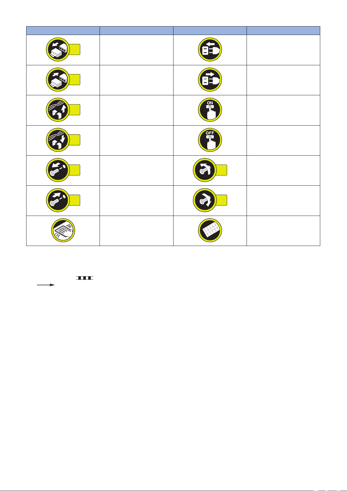
The following symbols are used throughout this Service Manual.
Symbols Explanation Symbols Explanation
Check.
Remove the claw.
Check visually.
Check a sound. Push the part.
Insert the claw.
1x
1x
1x
1x
1x
1x
1x
1x
Introduction
Symbols Explanation Symbols Explanation
Disconnect the connector. Connect the power cable.
Connect the connector. Disconnect the power cable.
Remove the cable/wire from the
cable guide or wire saddle.
Install the cable/wire to the cable
guide or wire saddle.
Remove the screw.
Install the screw.
Cleaning is needed. Measurement is needed.
The following rules apply throughout this Service Manual:
1. Each chapter contains sections explaining the purpose of specific functions and the relationship between electrical and
mechanical systems with reference to the timing of operation.
In the diagrams, represents the path of mechanical drive; where a signal name accompanies the symbol, the arrow
indicates the direction of the electric signal.
The expression "turn on the power" means flipping on the power switch, closing the front door, and closing the delivery unit
door, which results in supplying the machine with power.
2. In the digital circuits, '1' is used to indicate that the voltage level of a given signal is "High", while '0' is used to indicate "Low".
(The voltage value, however, differs from circuit to circuit.) In addition, the asterisk (*) as in "DRMD*" indicates that the DRMD
signal goes on when '0'.
In practically all cases, the internal mechanisms of a microprocessor cannot be checked in the field. Therefore, the operations
of the microprocessors used in the machines are not discussed: they are explained in terms of from sensors to the input of
the DC controller PCB and from the output of the DC controller PCB to the loads.
The descriptions in this Service Manual are subject to change without notice for product improvement or other purposes, and
major changes will be communicated in the form of Service Information bulletins.
All service persons are expected to have a good understanding of the contents of this Service Manual and all relevant Service
Information bulletins and be able to identify and isolate faults in the machine.
Turn on the power.
Turn off the power.
Loosen the screw.
Tighten the screw.

Contents
Contents
Safety Precautions...............................................................................................1
Power Supply...................................................................................................................................... 2
Notes Before Servicing........................................................................................................................2
Points to Note at Cleaning...................................................................................................................2
Notes On Assembly/Disassembly....................................................................................................... 2
Notes on Assembly/Disassembly........................................................................................................... 2
Points to Note when Tightening a Screw.................................................................................................2
1. Product Overview.............................................................................................4
Features.............................................................................................................................................. 5
Features...............................................................................................................................................5
Specifications...................................................................................................................................... 6
Finisher Unit......................................................................................................................................... 6
Staple Unit............................................................................................................................................7
Staple-free Staple Unit.......................................................................................................................... 8
Name of Parts..................................................................................................................................... 9
External View........................................................................................................................................9
Cross Section....................................................................................................................................... 9
2. Technical Explanation................................................................................... 10
Basic Configuration........................................................................................................................... 11
Functional Configuration......................................................................................................................11
Overview of Electrical Circuitry.............................................................................................................11
Controls.............................................................................................................................................12
Controls..............................................................................................................................................12
Basic Operation.................................................................................................................................13
Outline............................................................................................................................................... 13
Initialization.........................................................................................................................................15
Feed Unit...........................................................................................................................................16
Outline............................................................................................................................................... 16
Feeding Paper to Processing Tray Unit.................................................................................................16
Processing Tray Unit.........................................................................................................................18
Outline............................................................................................................................................... 18
Stacking Operation..............................................................................................................................18
Alignment/Shifting Operation................................................................................................................20
Staple Operation.................................................................................................................................26
Staple-free Staple Operation................................................................................................................27
Stack Delivery Operation..................................................................................................................... 29
Paper Retainer Operation....................................................................................................................30
Stack Tray Unit..................................................................................................................................31
Stack Tray Shift Operation...................................................................................................................31
Stack Tray Paper Height Detection Control...........................................................................................31
Stack Tray Paper Full Detection...........................................................................................................32
Jam Detection................................................................................................................................... 33
i

Contents
Outline............................................................................................................................................... 33
Power Supply.................................................................................................................................... 35
Outline............................................................................................................................................... 35
Protective Functions............................................................................................................................35
Upgrading..........................................................................................................................................36
Upgrading...........................................................................................................................................36
3. Periodical Service.......................................................................................... 37
List of Work for Scheduled Servicing................................................................................................ 38
4. Parts Replacement and Cleaning................................................................. 39
Notes at Parts Replacement............................................................................................................. 40
Removing this Machine.....................................................................................................................41
Removing this Machine from the Host Machine.....................................................................................41
List of Parts....................................................................................................................................... 49
External Cover....................................................................................................................................49
List of Main Unit.................................................................................................................................. 49
List of Solenoids..................................................................................................................................50
List of Motors......................................................................................................................................51
List of Fans.........................................................................................................................................52
List of Sensors/Switches......................................................................................................................52
List of PCBs........................................................................................................................................53
Other Parts.........................................................................................................................................54
External Cover...................................................................................................................................55
Removing the Front Cover Unit............................................................................................................ 55
Removing the Rear Cover....................................................................................................................55
Removing the Delivery Tray.................................................................................................................56
Installing the Delivery Tray...................................................................................................................56
Removing the Tray Guide Cover.......................................................................................................... 57
Main Unit........................................................................................................................................... 59
Removing the Upper Feed Guide Unit.................................................................................................. 59
Removing the Processing Tray Unit......................................................................................................60
Removing the Stapler Unit................................................................................................................... 64
Removing the Staple-free Staple Unit...................................................................................................65
Solenoids...........................................................................................................................................67
Removing the Paper Trailing Edge Pushing Guide Solenoid(SL1).......................................................... 67
Motor................................................................................................................................................. 68
Removing the Stapler Shift Motor (M7)................................................................................................. 68
Removing the Assist Motor (M5).......................................................................................................... 68
PCB...................................................................................................................................................70
Removing the Finisher Controller PCB..................................................................................................70
Sensor...............................................................................................................................................71
Removing the Delivery Sensor(PS1).....................................................................................................71
Removing the Disengaging Sensor (PS16)........................................................................................... 71
Other Parts........................................................................................................................................72
Removing the Return Belt Unit.............................................................................................................72
ii

Contents
5. Adjustment..................................................................................................... 75
Overview........................................................................................................................................... 76
Adjustment and Functional Setting in Service Mode.............................................................................. 76
Basic Adjustment Items....................................................................................................................... 78
Adjustment Items When Replacing Parts.............................................................................................. 78
Basic Adjustment...............................................................................................................................79
Alignment Plate Right-Angle Adjustment...............................................................................................79
Alignment Position Adjustment of the Alignment Plate .......................................................................... 81
Adjustment when Replacing the Parts.............................................................................................. 83
Handling Finisher Controller PCB Replacements...................................................................................83
Service Label.....................................................................................................................................84
Back-up of Service Mode.....................................................................................................................84
Service Label......................................................................................................................................84
6. Installation...................................................................................................... 85
How to Check this Installation Procedure .........................................................................................86
Symbols in the Illustration....................................................................................................................86
Checking before Installation..............................................................................................................87
Checking the Installation Space........................................................................................................... 87
Check Items when turning OFF the Main Power....................................................................................87
Points to Note at Installation.................................................................................................................87
Product Name.....................................................................................................................................87
Kontrollen vor der Installation (German/Deutsch)............................................................................. 88
Vorsichtshinweise zur Installation.........................................................................................................88
Unpacking......................................................................................................................................... 89
Unpacking Procedure..........................................................................................................................89
Checking the Contents........................................................................................................................ 90
Installation Outline Drawing................................................................................................................. 91
Installation Procedure........................................................................................................................92
Preparation for Host Machine...............................................................................................................92
Installation of Inner finisher.................................................................................................................. 94
Checking after Installation.................................................................................................................99
Disposal Parts Check.......................................................................................................................... 99
Operation Check.................................................................................................................................99
APPENDICES....................................................................................................100
Service Tools...................................................................................................................................101
Solvents and Oils.............................................................................................................................. 101
Special Tools.................................................................................................................................... 101
General Circuit Diagram..................................................................................................................102
General Circuit Diagram (1/1).............................................................................................................102
iii

Safety Precautions
Power Supply........................................2
Notes Before Servicing......................... 2
Points to Note at Cleaning.................... 2
Notes On Assembly/Disassembly.........2

Safety Precautions
Power Supply
CAUTION:
1. As a general rule, do not use extension cords. Using an extension cord may result in a fire or electrical shock. If an
extension cord must be used, however, use one for local rated voltage and over, untie the cord binding, and insert the
power plug completely into the extension cord outlet to ensure a firm connection between the power cord and the
extension cord.
2. The socket-outlet shall be installed near the equipment and shall be easily accessible.
Notes Before Servicing
CAUTION:
At servicing, be sure to turn off the power source of the host machine according to the specified steps and disconnect the
power plug.
CAUTION:
Do not turn off the power switch when downloading is under way. Turning off the main power switch while downloading is
under way can disable the machine.
Points to Note at Cleaning
CAUTION:
When performing cleaning using organic solvent such as alcohol, be sure to check that the component of solvent is
vaporized completely before assembling.
Notes On Assembly/Disassembly
Notes on Assembly/Disassembly
Follow the items below to assemble/disassemble the device.
1. Disconnect the power plug to avoid any potential dangers during assembling/disassembling works.
2. If not specially instructed, reverse the order of disassembly to reinstall.
3. Ensure to use the right screw type (length, diameter, etc.) at the right position when assembling.
4. To keep electric conduction, binding screws with washers are used to attach the grounding wire and the varistor. Ensure to
use the right screw type when assembling.
5. Unless it is specially needed, do not operate the device with some parts removed.
6. Never remove the paint-locked screws when disassembling.
7. During disassembly, reassembly or transportation of the printer, remove the cartridge if required. When the cartridge is out
of the printer, put it in a protective bag even in a short period of time to prevent the adverse effect of light.
8. When you replace the part that the rating plate or the product code label is attached, be sure to remove the rating plate or
the product code label and put it to the new part.
Points to Note when Tightening a Screw
For reduction in weight, thin plates are used in some parts of this machine.
2
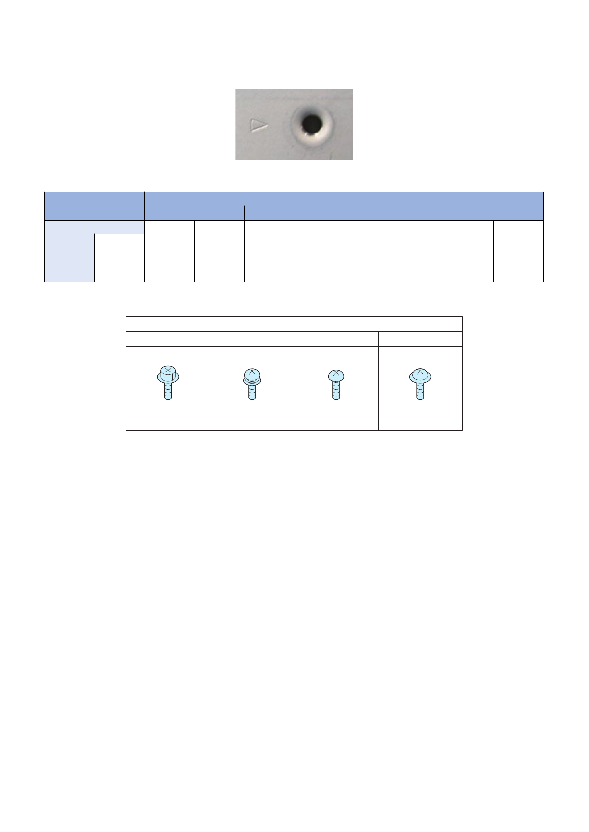
RS tight
Type of Screws
W Sems Binding TP
Safety Precautions
In the case of a screw hole with a triangle mark near it as shown in the figure below, strongly tightening the screw may damage
or deform the screw hole.
In the case of a screw hole with a triangle mark, take care not to apply too much force when tightening the screw.
The recommended torque value is shown below as a reference value.
Type of Screws
RS tight W Sems Binding TP
Fastened member Metal Resin Metal Resin Metal Resin Metal Resin
Tightening
torque
(N*m)
* For PCB, refer to the tightening torque value of resin (fastened member).
M4 Approx.
1.6
M3 Approx.
0.8
Approx.
1.6
Approx.
0.8
Approx.
1.6
Approx.
0.6
Approx.
0.8
Approx.
0.6
Approx.
1.6
Approx.
0.6
Approx.
0.8
Approx.
0.6
Approx.
1.6
Approx.
0.6
Approx.
0.8
Approx.
0.6
3

1
Product Overview
Features................................................5
Specifications........................................6
Name of Parts....................................... 9

1. Product Overview
Features
Features
• Compact, inner finisher compatible with color MFPs.
• Manual stapling, which enables paper to be inserted into the slit on the inner finisher and stapled manually a copy at a time.
• Staple-free stapling, which binds up to five sheets of paper without staples.
• Improved quietness with no initialization procedure.
• Easy to install in the host machine.
• The optional puncher unit can be installed in the finisher.
5

Specifications
Finisher Unit
Item Specifications Remarks
Stack tray Delivery tray
No.2 delivery tray (top of finisher)
Stacking method Delivery tray: Tray shift
No.2 delivery tray: Fixed
Stacking orientation Face down
Paper type Thin, plain, recycled, heavy, coated, transparency, label, bond, postcard, pre-
punched, envelope, tracing paper
Paper size Feed direction: 139.7 to 457.2 mm
Cross feed direction: 100 to 320 mm
However, COM10 (104.7 × 241.3 mm) and Monarch (98.4 × 190.5 mm) can be
fed as standard size paper.
Paper weight
Modes Non-sort stacking A3, A4, A4R, A5, A5R, B4, B5, B5R, 8K, 16K, 11X17,
Stack height detection Delivery tray Available (detects the top surface of the stacked pa-
Stacking capacity Processing tray Small size:*1 50 sheets or less
Alignment stacking
paper size
52 to 300 g/m 2 (The large size paper (257 to 300 g/m 2) is only a No.2 delivery
tray)
LGL, LTR, LTR-R, STMT, STMT-R, EXEC, 16K-R,
SRA3, 12X18, envelope, postcard, long paper (630
to 1200 mm)
Shift-sort stacking A3, A4, A4R, B4, B5, 11X17, LGL, LTR, LTR-R, 8K,
16K, EXEC
Staple stacking A3, A4, A4R, B4, B5, 11X17, LGL, LTR, LTR-R, 8K,
16K, EXEC
Staple-free staple stack-
ing
Manual stapling No size limitation
No.2 delivery tray Available (detects the top surface of the stacked pa-
No.2 delivery tray Small size:*1 Height 5.2 mm or less (equivalent to 50
Delivery tray Small size:*1 Height 52 mm or less (equivalent to 500
Stapling, staple-free sta-
pling
Non-sort stacking Cross feed direction: 100 to 320 mm
Shift-sort stacking Cross feed direction: 210 to 297 mm
A3, B4, A4, B5, 11X17, LTR, 8K, 16K • Stackability not defined.
per with a photosensor)
per with a sensor lever)
Large size:*2 30 sheets or less
sheets)
Large size:*2 Height 5.2 mm or less (equivalent to 50
sheets)
sheets)
Large size:*2 Height 26 mm or less (equivalent to
250 sheets)
Stack height indicated above, or 30 copies or less • The stacking capacities
(Monarch (width: 98.4 mm) can be fed as standard
size
1. Product Overview
• Long paper (630 to 1200
mm) can be used if it can
be fed through without
jamming.
• Shift amount: 30 mm
• Shiftable amount: 210 to
297 mm
• Stackability not defined.
• The stacking capacities
are estimates when converting weight to number
of 80 g/m 2 sheets. (The
cover includes two 256
g/m 2 sheets.)
• The stacking capacities
are estimates when converting weight to number
of 80 g/m 2 sheets.
• Stackability not defined
when 500 or more sheets
are stacked.
• Long paper (630 to 1200
mm) cannot be stacked.
are estimates when converting weight to number
of 80 g/m 2 sheets.
6
Item Specifications Remarks
Alignment stacking
paper size
Mixed stacking capacity
Dimensions (W x D xH)466 mm X 525 mm X 225 mm
Weight Approx. 8.6 kg
Power supply From host machine: 24 V, 5 V
Maximum power Approx. 64.4 W
Staple stacking, staplefree
Mixed size Delivery tray
Mixed staple stacking
and staple-free staple
stacking
Mixed modes Small size:*1 Height 52 mm or less (equivalent to 500
(585 mm X 525 mm X 225 mm)
Staple stacking
Cross feed direction: 210 to 297 mm
Staple-free stacking
Cross feed direction: 257 to 297 mm
Height 26 mm or less (equivalent to 250 sheets)
No.2 delivery tray
Height 5.2 mm or less (equivalent to 50 sheets)
Small size:*1 Height 52 mm or less (equivalent to 500
sheets)
Large size:*2 Height 26 mm or less (equivalent to
250 sheets), or 30 copies or less
sheets)
Large size:*2 Height 26 mm or less (equivalent to
250 sheets), or 30 copies or less
1. Product Overview
• The stacking capacities
are estimates when converting weight to number
of 80 g/m 2 sheets.
Dimensions when the auxiliary
tray is pulled out are shown in
parentheses.
*1: Small size (feed length: 216 mm or less)
A4, A5, A5R, B5, LTR, STMT, STMT-R, 16K, EXEC
*2: Large size (feed length: more than 216 mm to 457.2 mm)
A3, A4R, B4, B5R, 11X17, LGL, LTR-R, 8K, 16KR, SRA3, 12X18
Staple Unit
Item Specifications Remarks
Stapling method Punching by rotating cam • Flat clinch
Stapling position See below
Stapling paper size A3, B4, A4, A4R, B5, 11X17, LGL, LTR, LTR-R, 8K, 16K, EXEC
Stapling capacity Small size (A4, B5, LTR,
16K, EXEC)
Large size (A3, B4, A4R,
11X17, LGL, LTR-R, 8K)
Staple supply Special staple cartridge (5000 staples)
Staple detection Available • Remaining staples: 0 to 20
Manual stapling Available
Heavy 4.0 mm or less (64 g/m 2: equivalent to 45 sheets, 80 g/m 2: equivalent to 40 sheets)
Staple repositioning function
Available • Number of staples after sta-
52 to 81.4g/m2: 50 sheets
More than 81.4 to 105 g/m 2 : 30 sheets
More than 105 to 256 g/m 2 : 2 sheets
52 to 81.4g/m2: 30 sheets
More than 81.4 to 105 g/m 2 : 20 sheets
More than 105 to 256 g/m 2 : 2 sheets
• Heavy: 5.5 mm or less
• In cover mode, this includes
two heavy cover sheets.
• Stapling at only a single location
• No size limitation
ple-empty detection: 0 to 20
7
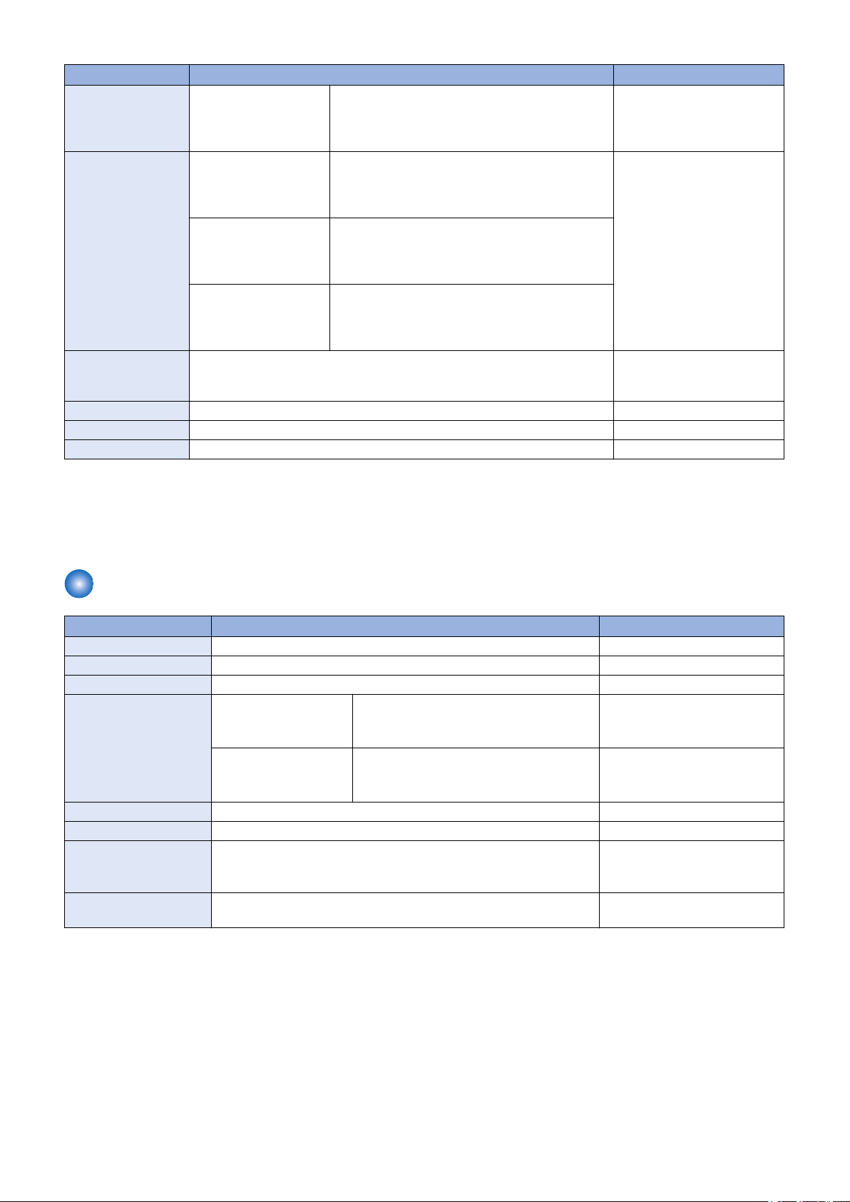
Center 2-point stapling
Front 1-point stapling (45 deg)
5.0 -/+ 2.0 mm
5.0 -/+ 2.0 mm
Rear 1-point stapling (45 deg)
5.0 -/+ 2.0 mm
5.0 -/+ 2.0 mm
Manual stapling
5.0 -/+ 2.0 mm
5.0 -/+ 2.0 mm
L3
Pitch
120
120
120
120
120
120
120
L3
5.0 -/+ 2.0
5.0 -/+ 2.0
5.0 -/+ 2.0
5.0 -/+ 2.0
5.0 -/+ 2.0
5.0 -/+ 2.0
5.0 -/+ 2.0
L2
203 -/+4.0
183 -/+ 4.0
194 -/+ 4.0
159.5 -/+ 4.0
162.5 -/+ 4.0
189.5 -/+ 4.0
188 -/+ 4.0
L1
83 -/+ 4.0
63 -/+ 4.0
74 -/+ 4.0
39.5 -/+ 4.0
42.5 -/+ 4.0
69.5 -/+ 4.0
68 -/+ 4.0
Paper size
A3, A4
B4, B5
11X17, LTR
A4R
LTRR, LGL
8K, 16K
EXEC
Unit (mm)
L1
L2
Alignment
front side
Alignment
back side
Rear 1-point stapling (30 deg)
13.5 -/+ 2.0 mm
3.0 mm or less
7.8 -/+ 2.0 mm
Delivery direction
Stapling position
1. Product Overview
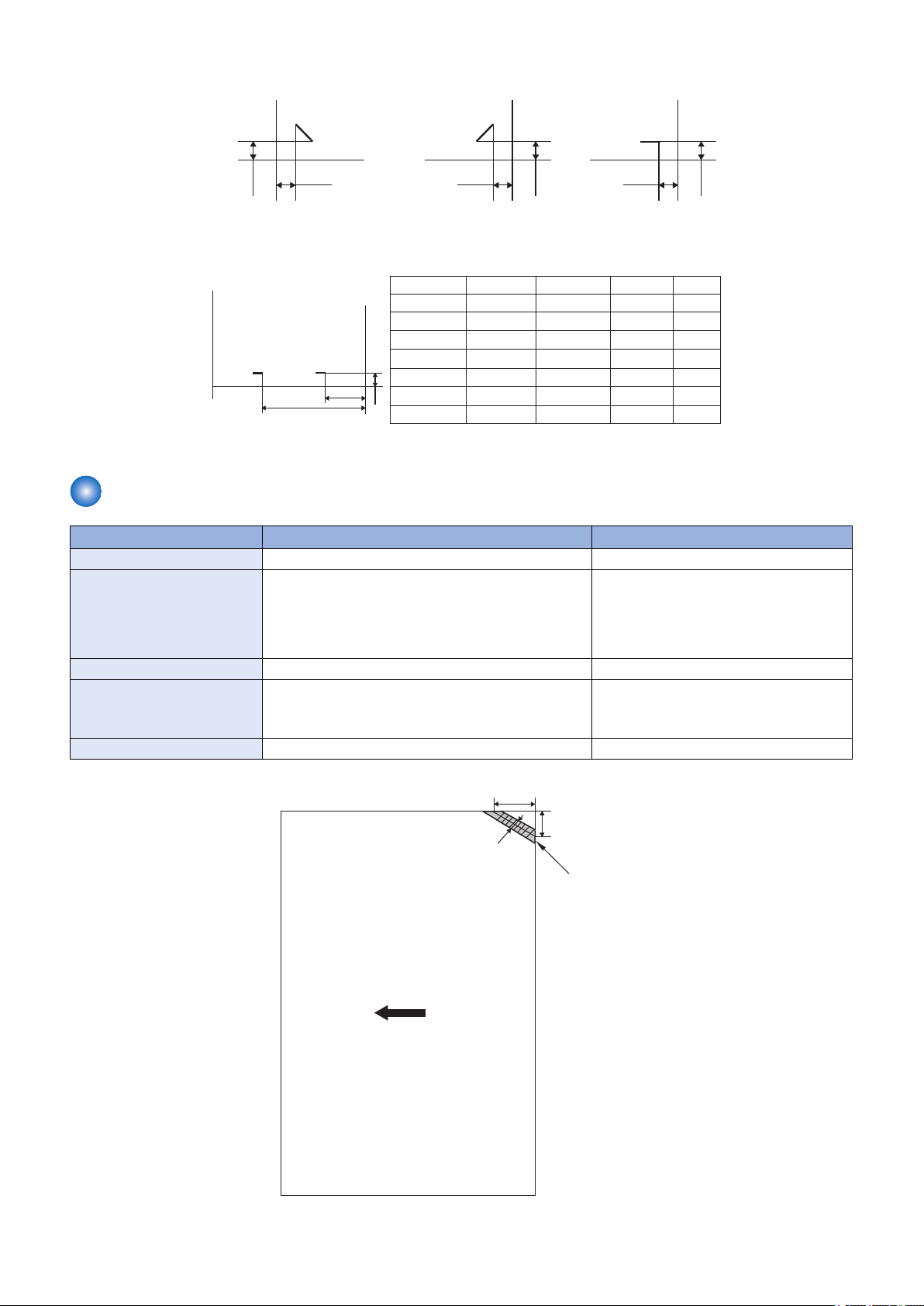
Staple-free Staple Unit
Item Specifications Remarks
Stapling method Pressing by rotating cam • Tooth-shaped clinch
Stapling position Rear 1-point stapling (see below) • Stapling at four locations (upper left,
Stapling size A3, B4, A4, B5, 11X17, LTR, 8K, 16K
Stapling capacity 52 to 64 g/m2: 5 sheets or less
Manual stapling None
More than 64 to 81.4 g/m 2 : 4 sheets or less
More than 81.4 to 105 g/m 2 : 3 sheets
upper right, lower right, lower left) is
possible using the host machine's LUI
through image processing of the printed
surface.
• Staplinga mix of same width is possible.
• Stapling a mix of different widths is not
possible.
8
Name of Parts
[1]
[2]
[6][7] [5] [3][4]
[1] [2] [3]
[8]
[4][5][6][7]
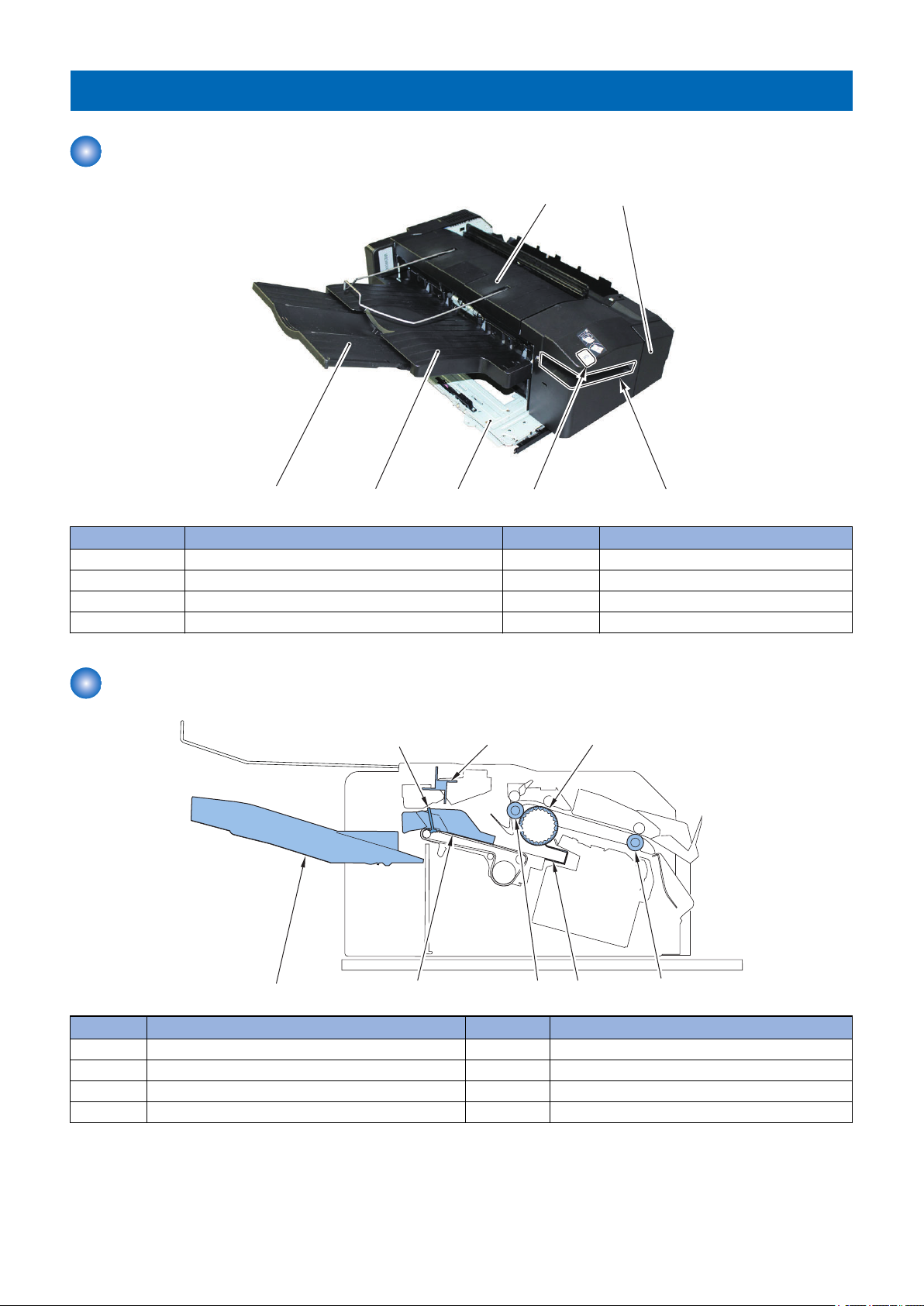
External View
1. Product Overview
No. Parts Name No. Parts Name
[1] No.2 Delivery Tray [5] Rail Unit
[2] Front Cover [6] Delivery Tray (Stack Tray)
[3] Slit [7] Auxiliary Tray
[4] Staple Button
Cross Section
No. Parts Name No. Parts Name
[1] Paper Retainer [5] Assist Guide
[2] Paddle [6] Delivery Roller
[3] Return Belt [7] Alignment Plate
[4] Inlet Roller [8] Delivery Tray
9

Technical
2
Explanation
Basic Configuration.............................11
Controls...............................................12
Basic Operation...................................13
Feed Unit.............................................16
Processing Tray Unit...........................18
Stack Tray Unit....................................31
Jam Detection..................................... 33
Power Supply......................................35
Upgrading............................................36
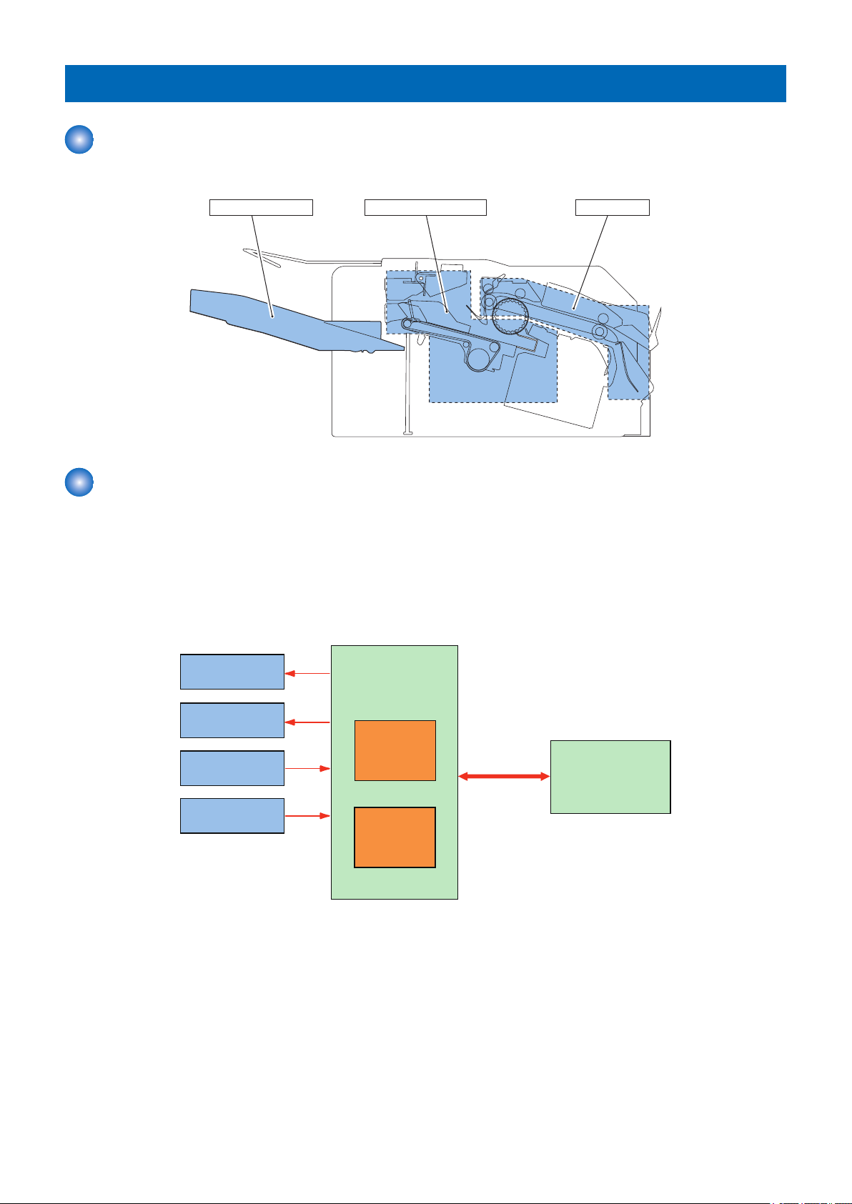
Stack Tray Unit Processing Tray Unit Feed Unit
Motor
Solenoid
Sensor
Switch
Motor Driver
Finisher Controller
PCB
CPU (IC1)
Host machine
(DC Controller PCB)
UFDI
communication
2. Technical Explanation
Basic Configuration
Functional Configuration
The components of this finisher are organized into 3 major blocks; feed unit, processing tray unit and stack tray unit.
Overview of Electrical Circuitry
This machine's sequence of the operation is controlled by the finisher controller PCB.
The finisher controller PCB has the CPU(IC1), and the controller also controls the communication with the host machine in addition
to controlling this machine's operation sequence.
The CPU(IC1) on the finisher controller PCB contains a flash ROM used to store the operating sequence program.
The finisher controller PCB uses the UFDI communication line to receive various commands from its host to drive the motors. It
also uses serial communications to send information on the sensors and switches to its host.
The setting value of the service mode in the finisher is memorized in CPU(IC1).
11

2. Technical Explanation
Controls
Controls
Item Reference
Basic Operation Outline “Outline” on page 13
Initialization “Initialization” on page 15
Feed Unit Outline “Outline” on page 16
Feeding Paper to Processing Tray Unit “Feeding Paper to Processing Tray Unit” on page
16
Processing Tray Unit Outline “Outline” on page 18
Stacking Operation “Stacking Operation” on page 18
Alignment/Shifting Operation “Alignment/Shifting Operation” on page 20
Staple Operation “Staple Operation” on page 26
Staple-free Stapling Operation “Staple-free Staple Operation” on page 27
Delivery Operation “Stack Delivery Operation” on page 29
Paper Retainer Operation “Paper Retainer Operation” on page 30
Stack Tray Unit Stack Tray Shift Operation “Stack Tray Shift Operation” on page 31
Stack Tray Paper Height Detection “Stack Tray Paper Height Detection Control” on
page 31
Stack Tray Paper Full Detection “Stack Tray Paper Full Detection” on page 32
Jam Detection Outline “Outline” on page 33
Power Supply Outline “Outline” on page 35
Protective Functions “Protective Functions” on page 35
Upgrading Outline “Upgrading” on page 36
12
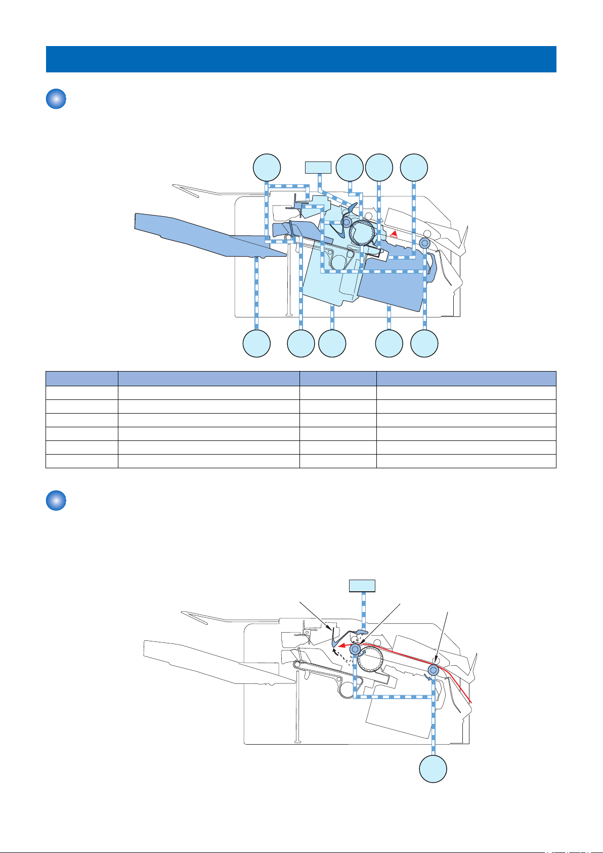
Delivery Roller
Inlet Roller
Paper Trailing Edge Pushing Guide
Return Belt
Paddle
Stopper
2. Technical Explanation
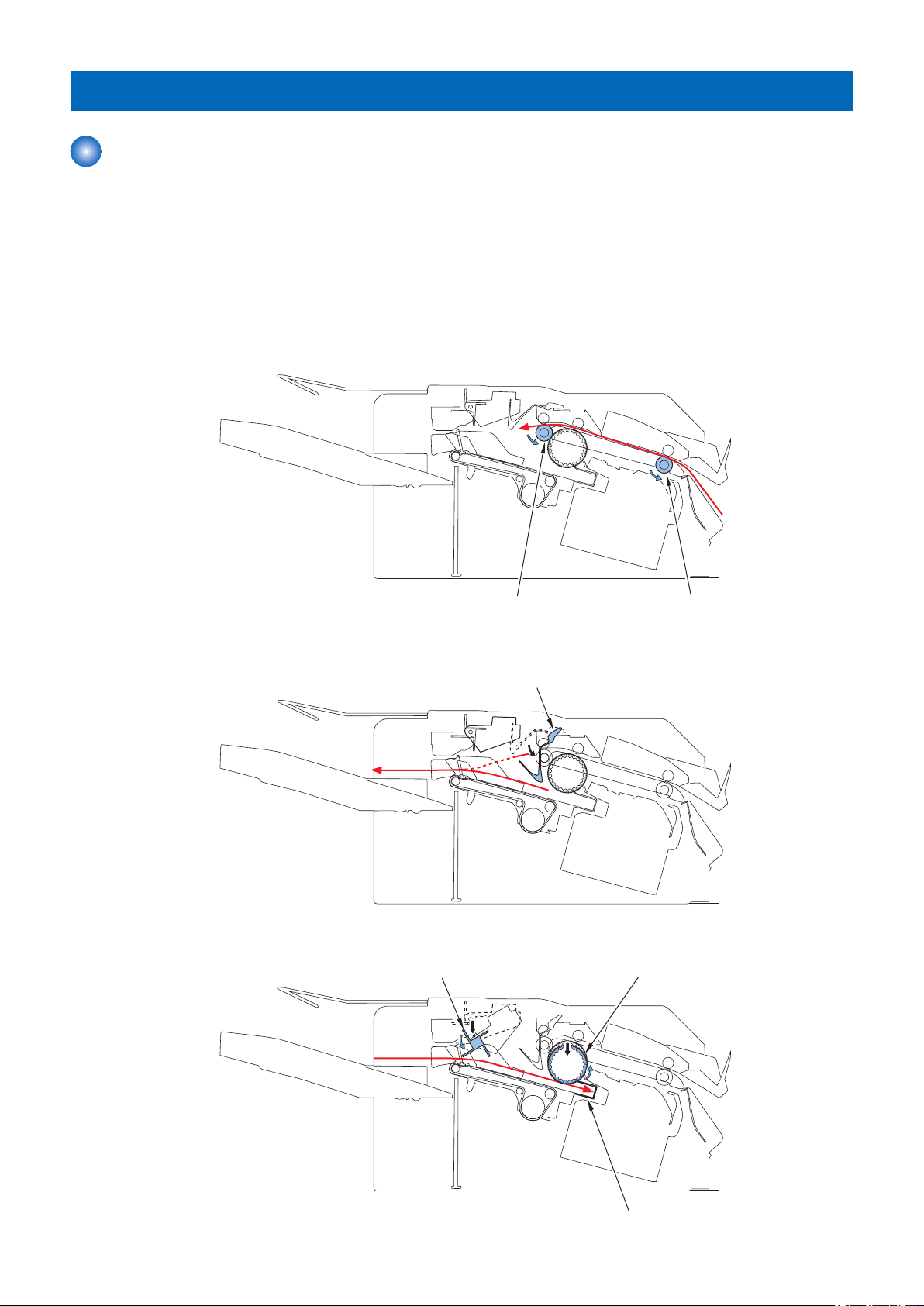
Basic Operation
Outline
The finisher operates according to the commands that it receives from the host machine and ejects paper to the delivery tray.
There are four paper delivery methods.
• Non-sort stacking
• Shift-sort stacking
• Staple stacking
• Staple-free staple stacking
Basic operations of this finisher are described below.
1. The paper delivered from the host machine is fed by the inlet roller and delivery roller.
2. The trailing edge of the paper delivered by the delivery roller is pushed on the processing tray by the paper trailing edge
pushing guide.
3. The paper is fed toward the processing tray by the paddle. The return belt feeds the paper to the processing tray's stopper
and aligns paper in the feed direction.
13

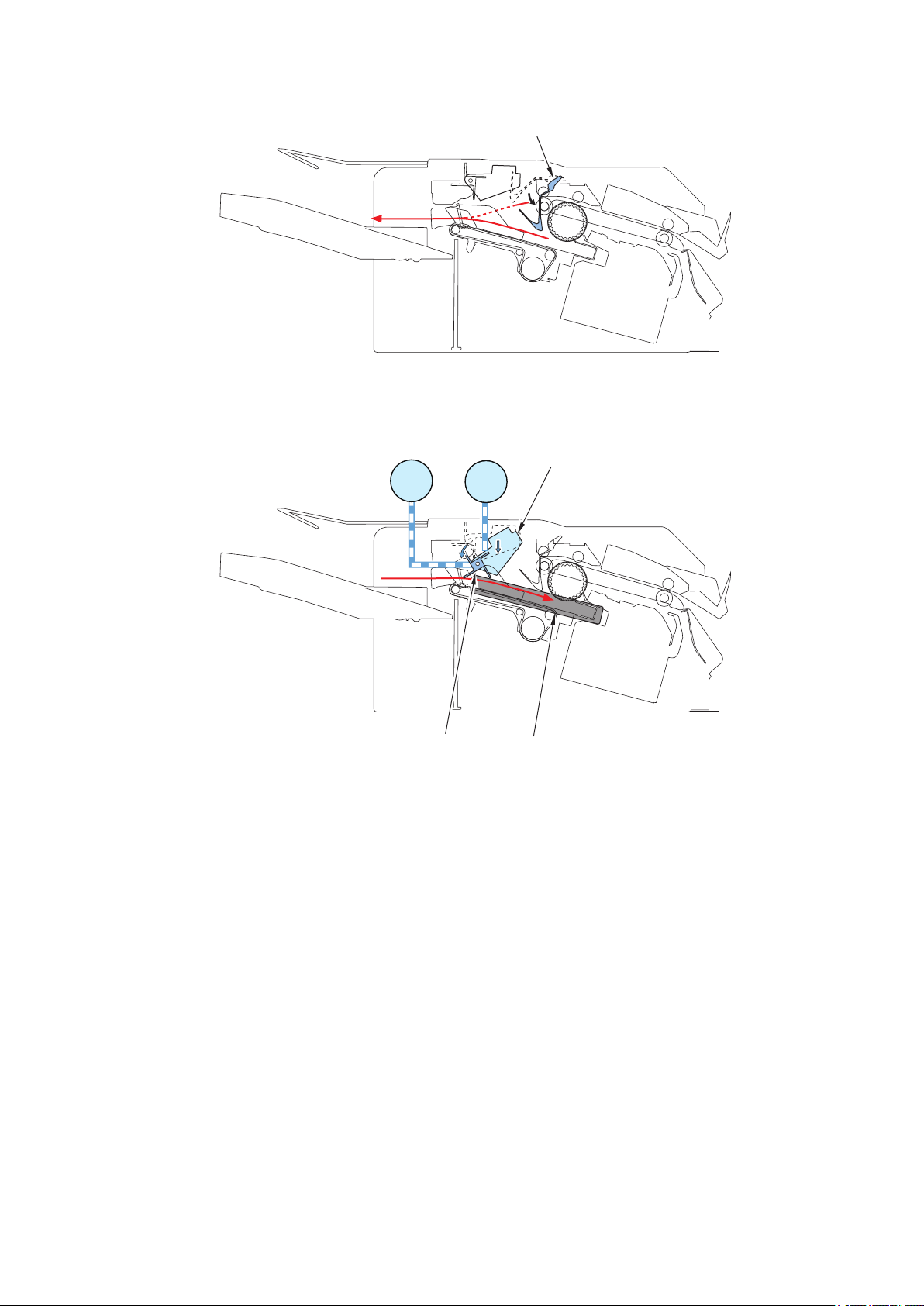
Rear Alignment Plate
Front Alignment Plate
Stapler Unit
Staple-free Staple Unit
2. Technical Explanation
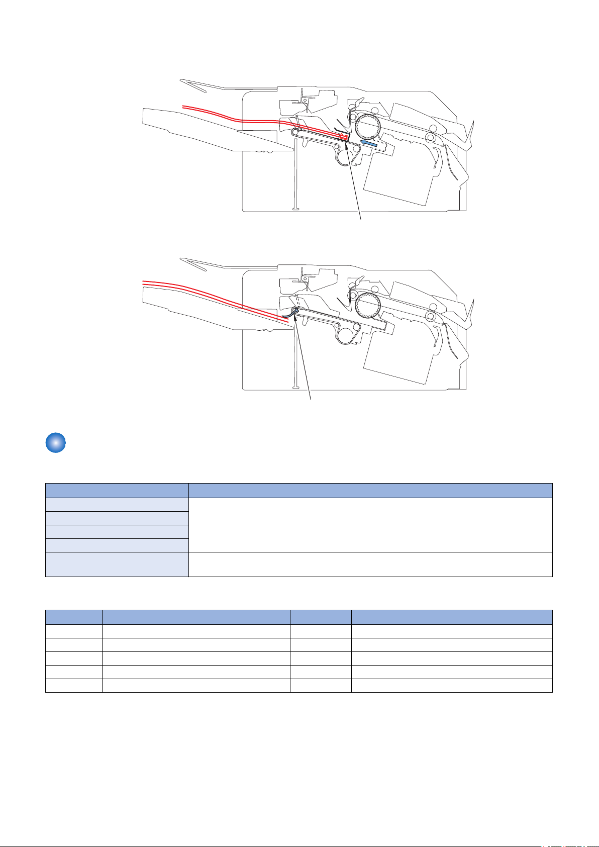
4. The alignment plates are used to align paper in the width direction. (In the illustration below, paper is aligned with reference
to the central reference position.)
5. The operations described in steps 1 to 4 are repeated for each sheet to stack the sheets on the processing tray.
6. The stacked sheets are stapled or staple-free stapled (only when in the relevant mode).
14
Assist Guide
Paper Retainer
2. Technical Explanation
7. After being shifted, the paper stack on the processing tray that has been stacked by the assist guide is delivered to the
delivery tray.
8. After the paper stack has been delivered, the paper retainer holds down the stack in the delivery tray.
Initialization
The finisher performs the following initialization operation depending on the status.
Status Operation
At power ON If the target sensors*1 are aware of the home positions, initialization is not performed.
When recovering from sleep mode
At the start of a job
At the end of a job
After the cover is closed Initialization is performed regardless of the sensor status. If at the home position, initialization is
*1: Target sensors
Symbol Parts Name Symbol Parts Name
PS2 Paddle HP Sensor PS8 Paper Hold HP Sensor
PS3 Return Belt HP Sensor PS9 Stack Tray Paper Height Sensor
PS4 Front Alignment Plate HP Sensor PS11 Stapler Shift HP Sensor
PS5 Rear Alignment Plate HP Sensor PS14 Stack Tray HP Sensor
PS7 Assist HP Sensor PS15 Clinch HP Sensor
Only before starting a job, the stack tray paper height sensor (PS9) detects the paper height.
performed by moving the sensor away from the home position.
15
M7M6 M9
M2 M8
PS1
M3/4
M5
M1
M10
SL1
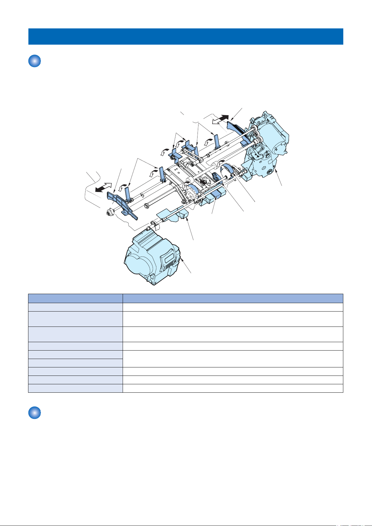
Inlet Roller
Delivery Roller
M1
SL1
Paper Trailing Edge
Pushing Guide
2. Technical Explanation
Feed Unit
Outline
The feed unit feeds the paper delivered from the host machine to the processing tray unit.
A delivery sensor (PS1) is provided along the paper feed path in the feed unit to detect the paper feed state and jam.
Symbol Parts Name Symbol Parts Name
M1 Feed Motor M7 Stapler Shift Motor
M2 Return Belt Motor M8 Stapler Motor
M3 Front Alignment Motor M9 Clinch Motor
M4 Rear Alignment Motor M10 Paddle Motor
M5 Assist Motor PS1 Delivery Sensor
M6 Tray Shift Motor SL1 Paper Trailing Edge Pushing Guide Solenoid
Feeding Paper to Processing Tray Unit
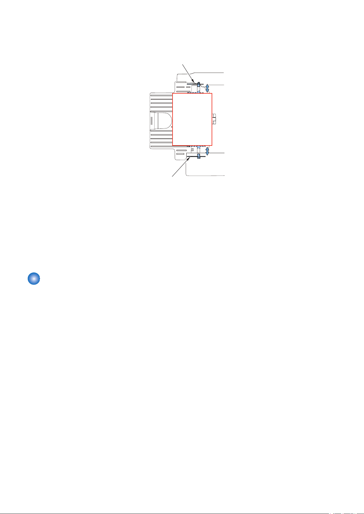
1. The paper delivered from the host machine is fed by the inlet roller and delivery roller.
The inlet roller and delivery roller are driven by the feed motor (M1).
The paper trailing edge pushing guide is lifted by turning ON the paper trailing edge pushing guide solenoid (SL1) to secure
the paper feed path.
16
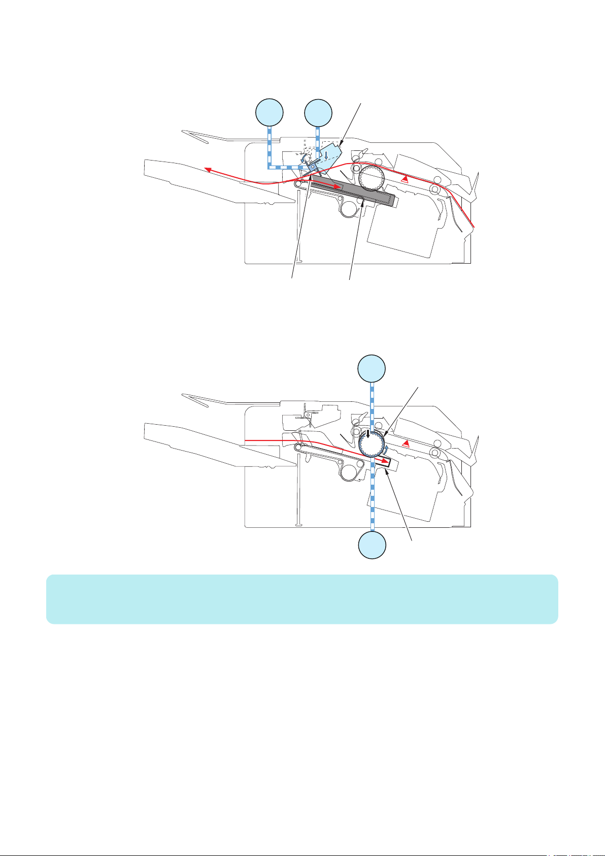
Paper Trailing Edge Pushing Guide
M10
M1
Paddle
Processing Tray Unit
Paddle Unit
2. Technical Explanation
2. The trailing edge of the paper delivered by the delivery roller is pushed on the processing tray by the paper trailing edge
pushing guide.
3. The paper is stacked on the processing tray by the paddle.
The paddle is driven by the feed motor (M1).
When the paddle motor (M10) runs, the paddle unit moves down. The paddle makes contact with the paper and feeds the
paper to the processing tray unit.
17
Front Alignment Plate
Rear Alignment Plate
Paddle
Assist Guide
Stopper
Stapler Unit
Return Belt
Staple-free
Staple Unit
Assist Claw
Paper Retainer
Delivery tray
Paper Retainer
2. Technical Explanation
Processing Tray Unit
Outline
The processing tray unit aligns, shifts, and staples or staples without staples the delivered paper. Then the assist guide and assist
claw deliver the paper onto the delivery tray.
The names and functions of the components of the processing tray are as follows:
Paddle Feeds the paper delivered from the delivery roller to the processing tray unit.
Return Belt Feeds the paper to the rear of the processing tray unit and presses the paper against the
Stopper Allows the paper stacked on the processing tray to be pressed against itself to align the paper
Front/Rear Alignment Plate Aligns the paper stacked on the processing tray in the width direction and shifts the paper.
Assist Guide The assist guide supports the trailing edge of the paper stacked on the processing tray unit,
Assist Claw
Stapler Unit Staples the sheets.
Staple-free Staple Unit Staples sheets without using staples.
Paper Retainer Holds down the paper stack in the delivery tray.
Stacking Operation
The paper delivered from the delivery roller is stacked on the processing tray and aligned in the feed direction.
How paper is delivered from the delivery roller and stacked on the processing tray is described below.
Name Function
stopper.
in the feed direction.
and the assist claw delivers the paper stack by pushing the stack onto the delivery tray.
18
Paddle
Paddle Unit
Processing Tray Unit
M10
M1
PS1
M2
M1
PS1
Return Belt
Stopper
2. Technical Explanation
1. After the delivery sensor (PS1) detects the trailing edge of the paper, the paddle motor (M10) runs to move the paddle unit
down. The paddle driven by the feed motor (M1) delivers the paper toward the processing tray. After a given time elapses,
the paddle unit is moved up.
2. After the delivery sensor (PS1) detects the trailing edge of the paper, the return belt motor (M2) runs to move the return belt
unit down. The delivered paper is pressed against the stopper by the return belt driven by the feed motor (M1) and aligned
in the feed direction.
After a given time elapses, the return belt unit is moved up.
NOTE:
Paper is not fed by the returned belt if the paper width is more than 297.0 mm or less than 120 mm or if the paper is special paper
or envelopes.
19
Rear Alignment Plate
Front Alignment Plate
2. Technical Explanation
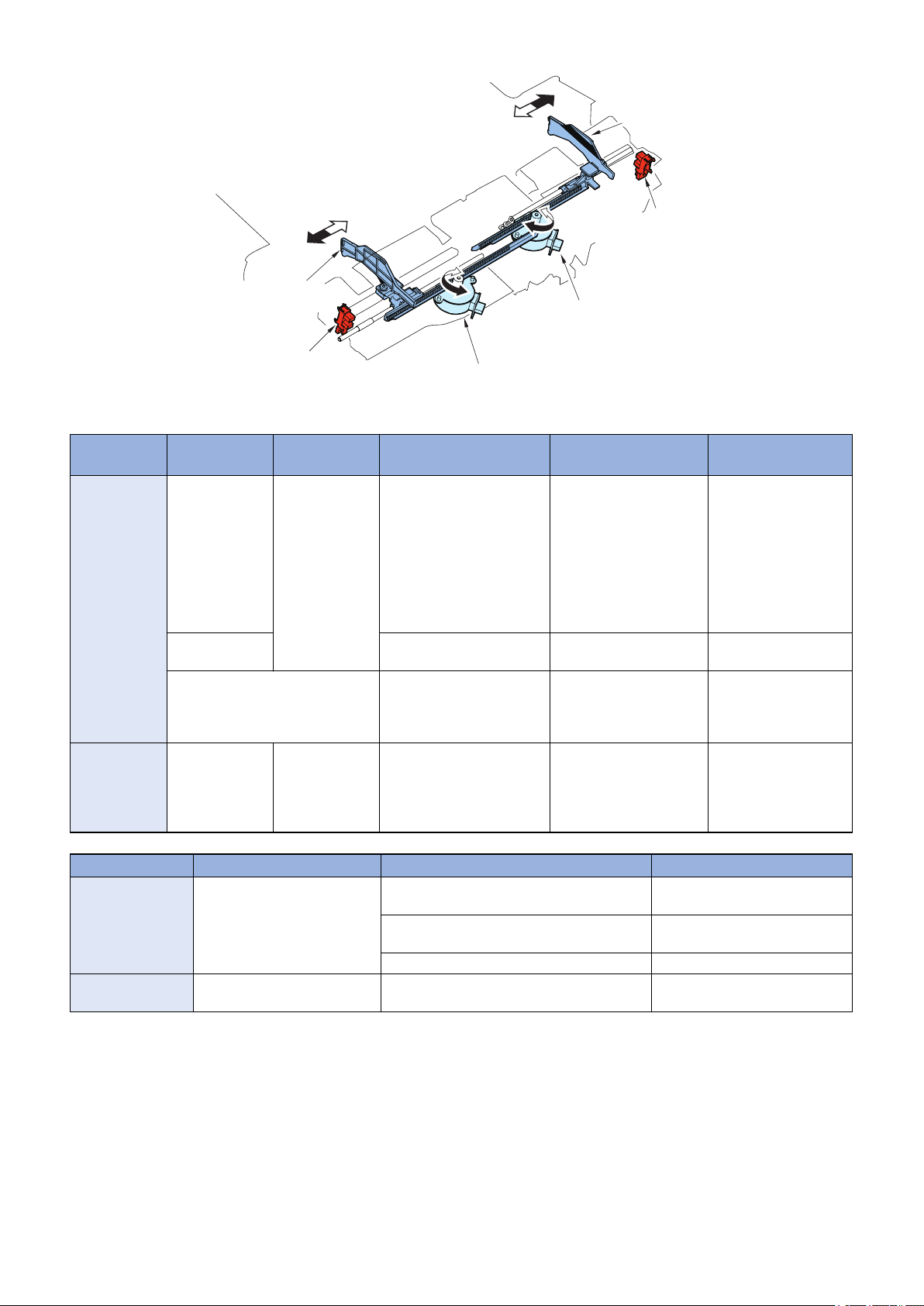
3. The front/rear alignment motors (M3/M4) operate to move the front and rear alignment plates, thus aligning the paper in the
width direction. (In the illustration below, paper is aligned with reference to the central reference position.)
Operations described in steps 1 to 3 are repeated for each sheet.
Related service mode
• Adjustment of return belt pressure:
SORTER > ADJUST > RBLT-PRS
Related error code
• E535-0001: Return belt motor error
• E535-0002: Return belt motor error
• E577-8001: Paddle motor error
• E577-0002: Paddle motor error
Alignment/Shifting Operation
■ Outline
The paper stacked on the processing tray is aligned in the width direction by the front and rear alignment plates.
Then, the paper is delivered to the delivery tray.
When shift sort is specified, the paper stacked on the processing tray is aligned to the front or rear and shifted to sort the paper
stack.
The front alignment plate is driven by the front alignment motor (M3) and the rear alignment plate by the rear alignment motor
(M4). The home positions of the alignment plates are detected by the front alignment HP sensor (PS4) and rear alignment HP
sensor (PS5).
20
Rear Alignment
Plate
Rear Alignment Motor (M4)
Front Alignment Plate
HP Sensor (PS4)
Rear Alignment Plate
HP Sensor (PS5)
Front Alignment Motor (M3)
Front Alignment
Plate
2. Technical Explanation
The relationship between operation modes and alignment positions is summarized in the following table.
Operation
Non-Sort 297.0 mm or less Not defined envelope (COM10-R, Mon-
Shift-Sort 210.0 to 297.0mm173.4 to 215.9mmA3, A4, A4R, B4, B5, 11X17,
Operation Mode Paper Size Alignment Position Remarks
Staple A3, B4, A4, A4R, B5, 11X17,
Staple-free staple A3, B4, A4, B5, 11X17, LTR,
Related service mode
• Adjustment of alignment position (A4):
• Adjustment of alignment position (LTR):
Related error code
• E537-8001: Front alignment motor error
• E537-8002: Front alignment motor error
• E530-8001: Rear alignment motor error
Paper Width Paper Length Standard Paper Alignment Position Remarks
Mode
More than 297.0
mm
Free size Center alignment (howev-
LGL, LTR, LTR-R, 8K, 16K, EXEC
8K, 16K
SORTER > ADJUST > INF-ALG1
SORTER > ADJUST > INF-ALG2
arch-R, DLR), STMTR, A5R,
B5R, EXEC-R, K16R, A5,
STMT, A4, LTR, K16, A3,
11X17, K8
SRA3, 12X18 20 mm front of the center
LTR-R, LGL, LTR, 8K , 16K,
EXEC
Front 1-point stapling: Front of the paper stack
End face at 148.5 mm in front of the center
Rear 1-point stapling: Rear of the paper stack
End face at 148.5 mm to the rear of the center
2-point stapling: Center alignment
Rear of the paper stack
End face at 148.5 mm to the rear of the center
Center alignment*1 *1: If the width is less
than 120.0 mm, the
alignment plate does
not reach the end of the
paper. Therefore, alignment is made at +8 mm
from the end of the paper for the front and
rear.
position
er, 20 mm in front of the
center position if the width
is more than 297 mm)
Front shift: 20 mm in front
of the center position
Rear shift: 10 mm to the
rear of the center position
Shift amount: 30 mm
Center alignment is used for A4
and A3(paper width 297 mm).
Center alignment is used for A4
and A3(paper width 297 mm).
21
Rear Alignment Plate
Front Alignment Plate
End of Paper
+5 mm
Middle of Feeding Path
End of Paper
+5 mm
5 mm
5 mm
Rear Alignment Plate
Middle of Feeding Path
Front Alignment Plate
Rear Alignment Plate
End of Paper
+5 mm
Middle of Feeding Path
End of Paper
+20 mm
Front Alignment Plate
2. Technical Explanation
• E530-8002: Rear alignment motor error
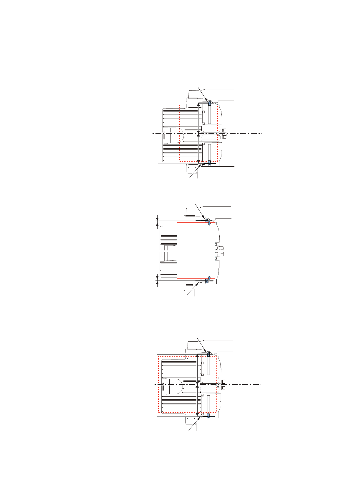
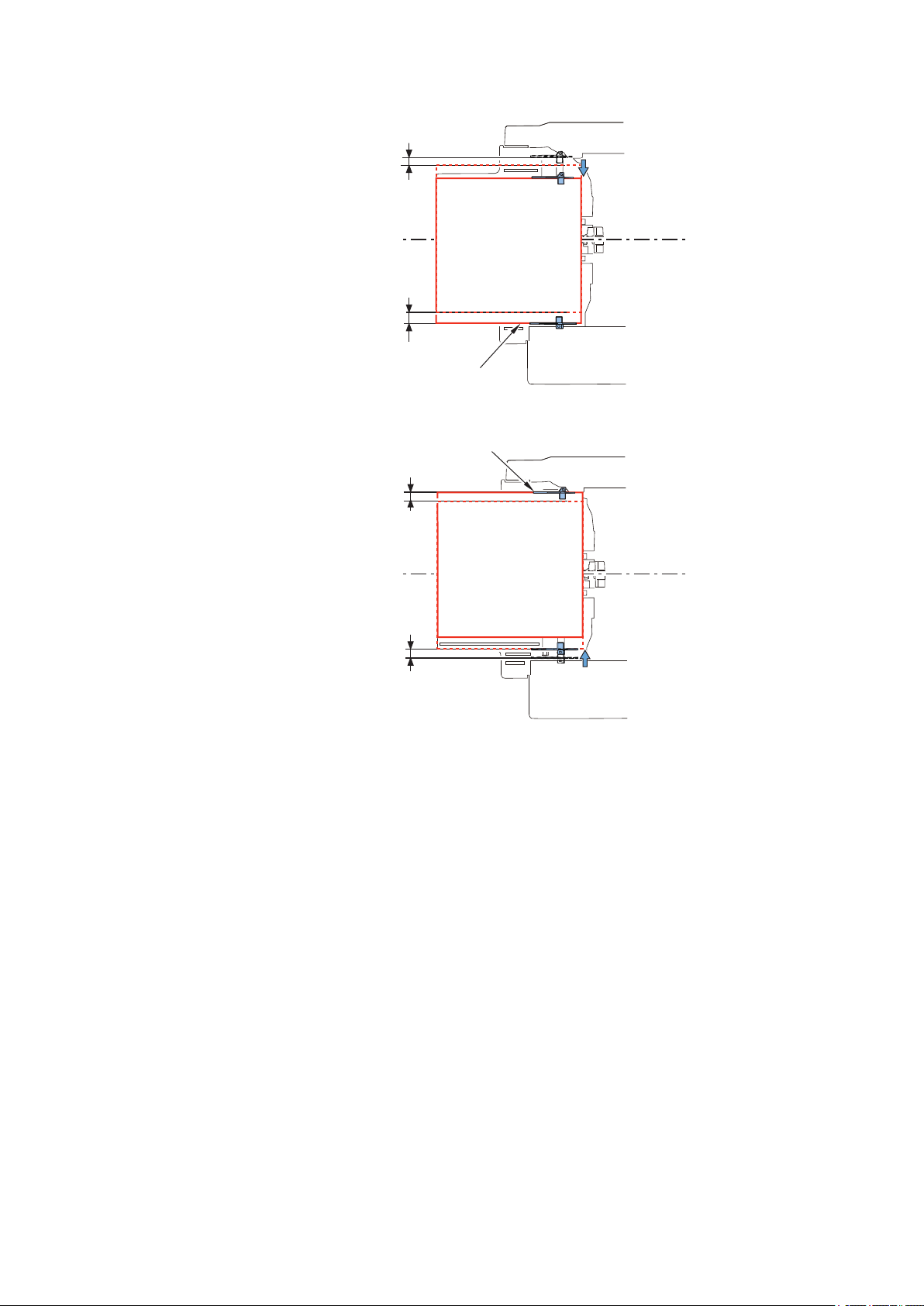
■ Alignment Operation in Non-sort Mode
When the paper width is 297.0 mm or less (A4, LTR, etc.)
1. After the delivery sensor (PS1) detects the trailing edge of the paper, the front and rear alignment plates move to the wait
positions (paper width + 5 mm).
2. Move the front and rear alignment plates to align the paper (center alignment).
When the paper width is more than 297.0 mm (SRA3, 12X18)
1. After the delivery sensor (PS1) detects the paper, the front and rear alignment plates move to the wait positions (paper width
+ 20 mm and paper width + 5 mm, respectively).
22
25 mm
Rear Alignment Plate
Middle of Feeding Path
Alignment Position
Front Alignment Plate
Rear Alignment Plate
End of Paper
+5 mm
Middle of Feeding Path
End of Paper
+20 mm
Front Alignment Plate
Rear Alignment Plate
End of Paper
+10 mm
Middle of Feeding Path
End of Paper
+5 mm
Front Alignment Plate
2. Technical Explanation
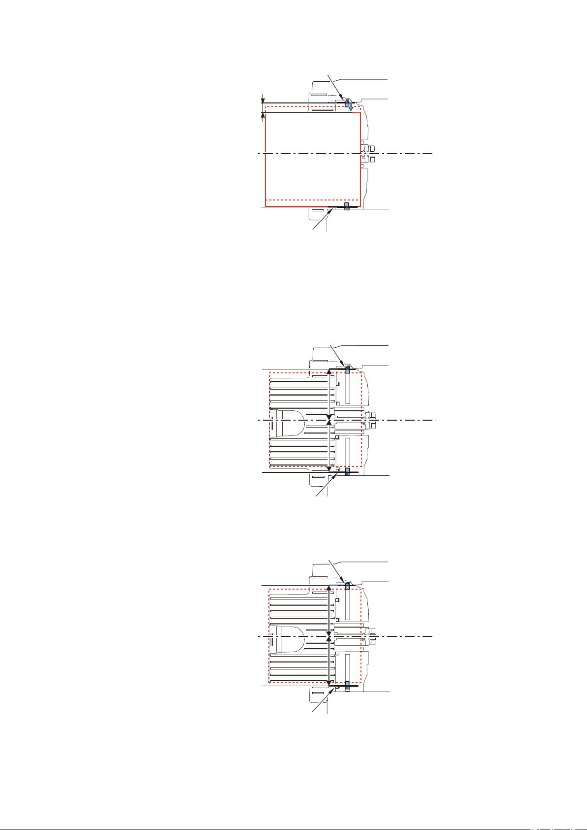
2. Move the rear alignment plate to align the paper.
■ Alignment Operation in Shift-sort Mode
1. After the delivery sensor (PS1) detects the trailing edge of the paper, the front and rear alignment plates move to the wait
positions.
• Wait positions during front shift (front alignment plate position: paper width +20 mm, rear alignment plate position: paper
width +5 mm)
• Wait positions during rear shift (front alignment plate position: paper width +5 mm, rear alignment plate position: paper
width +10 mm)
23
2. Move the front and rear alignment plates to align the paper.
Front Alignment Position
Middle of Feeding Path
5 mm
20 mm
Rear Alignment Position
Middle of Feeding Path
10mm
5mm
• During front shift, move only the rear alignment plate.(Do not move the front alignment plate.)
• During rear shift, move only the front alignment plate.(Do not move the rear alignment plate.)
2. Technical Explanation
24
 Loading...