

Canon imagePROGRAF iPF5000 Series Service Manual

Service Manual
iPF5000 series
iPF5000
May 9 2006


Application
This manual has been issued by Canon Inc. for qualified persons to learn technical theory, installation, maintenance, and repair
of products. This manual covers all localities where the products are sold. For this reason, there may be information in this
manual that does not apply to your locality.
Corrections
This manual may contain technical inaccuracies or typographical errors due to improvements or changes in products. When
changes occur in applicable products or in the contents of this manual, Canon will release technical information as the need
arises. In the event of major changes in the contents of this manual over a long or short period, Canon will issue a new edition
of this manual.
The following paragraph does not apply to any countries where such provisions are inconsistent with local law.
Trademarks
The product names and company names used in this manual are the registered trademarks of the individual companies.
Copyright
This manual is copyrighted with all rights reserved. Under the copyright laws, this manual may not be copied, reproduced or
translated into another language, in whole or in part, without the written consent of Canon Inc.
COPYRIGHT © 2001 CANON INC.
Printed in Japan
Caution
Use of this manual should be strictly supervised to avoid disclosure of confidential information.
Symbols Used
This documentation uses the following symbols to indicate special information:
Symbol Description
Indicates an item of a non-specific nature, possibly classified as Note, Caution, or Warning.
Indicates an item requiring care to avoid electric shocks.
Indicates an item requiring care to avoid combustion (fire).
Indicates an item prohibiting disassembly to avoid electric shocks or problems.
Indicates an item requiring disconnection of the power plug from the electric outlet.
Indicates an item intended to provide notes assisting the understanding of the topic in question.
Memo
Introduction
REF.
Indicates an item of reference assisting the understanding of the topic in question.
Provides a description of a service mode.
Provides a description of the nature of an error indication.
i

Introduction
The following rules apply throughout this Service Manual:
1. Each chapter contains sections explaining the purpose of specific functions and the relationship between electrical and mechanical systems with reference to the timing of operation.
In the diagrams, represents the path of mechanical drive; where a signal name accompanies the symbol , the arrow indicates the
direction of the electric signal.
The expression "turn on the power" means flipping on the power switch, closing the front door, and closing the delivery unit door, which results in
supplying the machine with power.
2. In the digital circuits, '1'is used to indicate that the voltage level of a given signal is "High", while '0' is used to indicate "Low".(The voltage value,
however, differs from circuit to circuit.) In addition, the asterisk (*) as in "DRMD*" indicates that the DRMD signal goes on when '0'.
In practically all cases, the internal mechanisms of a microprocessor cannot be checked in the field. Therefore, the operations of the microprocessors
used in the machines are not discussed: they are explained in terms of from sensors to the input of the DC controller PCB and from the output of the
DC controller PCB to the loads.
The descriptions in this Service Manual are subject to change without notice for product improvement or other purposes, and major changes will be communicated in the form of Service Information bulletins.
All service persons are expected to have a good understanding of the contents of this Service Manual and all relevant Service Information bulletins and be
able to identify and isolate faults in the machine."
ii


Contents
Contents
Chapter 1 PRODUCT DESCRIPTION
1.1 Product Overview ........................................................................................................................................... 1- 1
1.1.1 Product Overview .................................................................................................................................... 1- 1
1.2 Features ........................................................................................................................................................... 1- 1
1.2.1 Printhead................................................................................................................................................... 1- 1
1.2.2 Ink Tank..................................................................................................................................................... 1- 2
1.2.3 Cutter......................................................................................................................................................... 1- 2
1.2.4 Auto Roll Feed Unit ................................................................................................................................. 1- 2
1.2.5 Consumables............................................................................................................................................ 1- 3
1.3 Product Specifications ................................................................................................................................... 1- 4
1.3.1 Product Specifications ............................................................................................................................ 1- 4
1.4 Detailed Specifications................................................................................................................................... 1- 5
1.4.1 Printing Speed and Direction................................................................................................................. 1- 5
1.4.2 Interface Specifications........................................................................................................................... 1- 5
1.5 Names and Functions of Components........................................................................................................ 1- 7
1.5.1 Front........................................................................................................................................................... 1- 7
1.5.2 Rear ........................................................................................................................................................... 1- 7
1.5.3 Carriage..................................................................................................................................................... 1- 8
1.5.4 Inside ......................................................................................................................................................... 1- 8
1.6 Basic Operation............................................................................................................................................... 1- 9
1.6.1 Operation Panel ....................................................................................................................................... 1- 9
1.6.2 Printer Stats Transition ......................................................................................................................... 1- 10
1.6.3 Main Menu .............................................................................................................................................. 1- 10
1.7 Safety and Precautions................................................................................................................................1- 17
1.7.1 Safety Precautions................................................................................................................................. 1- 17
1.7.1.1 Moving Parts.................................................................................................................................... 1- 17
1.7.1.2 Adhesion of Ink ............................................................................................................................... 1- 17
1.7.1.3 Electric Parts.................................................................................................................................... 1- 18
1.7.2 Other Precautions .................................................................................................................................. 1- 19
1.7.2.1 Printhead.......................................................................................................................................... 1- 19
1.7.2.2 Ink Tank............................................................................................................................................ 1- 20
1.7.2.3 Handling the Printer........................................................................................................................ 1- 20
1.7.3 Precautions When Servicing Printer ................................................................................................... 1- 22
1.7.3.1 Notes on the Data Stored in the Printer ...................................................................................... 1- 22
1.7.3.2 Confirming the Firmware Version................................................................................................. 1- 22
1.7.3.3 Precautions against Static Electricity........................................................................................... 1- 22
1.7.3.4 Precautions for Disassembly/Reassembly ................................................................................. 1- 22
1.7.3.5 Self-diagno stic Feature................................................................................................................. 1- 22
1.7.3.6 Disposing of the Lithium Battery................................................................................................... 1- 22
Chapter 2 TECHNICAL REFERENCE
2.1 Basic Operation Outline................................................................................................................................. 2- 1

Contents
2.1.1 Printer Diagram ........................................................................................................................................ 2- 1
2.1.2 Print Driving .............................................................................................................................................. 2- 2
2.2 Firmware .......................................................................................................................................................... 2- 2
2.2.1 Operation Sequence at Power-on......................................................................................................... 2- 2
2.2.2 Operation Sequence at Power-off......................................................................................................... 2- 2
2.2.3 Print Control.............................................................................................................................................. 2- 3
2.2.4 Print Position Adjustment Function ....................................................................................................... 2- 4
2.2.5 Head Management.................................................................................................................................. 2- 4
2.2.6 Printhead Overheating Protection Control........................................................................................... 2- 4
2.2.7 Pause between Pages............................................................................................................................ 2- 4
2.2.8 White Raster Skip .................................................................................................................................... 2- 4
2.2.9 Sleep Mode............................................................................................................................................... 2- 4
2.3 Printer Mechanical System ........................................................................................................................... 2- 6
2.3.1 Outline........................................................................................................................................................ 2- 6
2.3.1.1 Outline ................................................................................................................................................ 2- 6
2.3.2 Ink Passage............................................................................................................................................... 2- 6
2.3.2.1 Ink Passage ....................................................................................................................................... 2- 6
2.3.2.2 Ink Tank Unit ..................................................................................................................................... 2- 7
2.3.2.3 Carriage Unit ..................................................................................................................................... 2- 9
2.3.2.4 Printhead.......................................................................................................................................... 2- 12
2.3.2.5 Purge Unit ........................................................................................................................................ 2- 12
2.3.2.6 Maintenance Cartridge................................................................................................................... 2- 16
2.3.2.7 Air Flow............................................................................................................................................. 2- 16
2.3.3 Paper Path............................................................................................................................................... 2- 17
2.3.3.1 Outline .............................................................................................................................................. 2- 17
2.3.3.2 Paper Path ....................................................................................................................................... 2- 18
2.3.3.3 Cutter Unit........................................................................................................................................ 2- 29
2.4 Printer Electrical System ............................................................................................................................. 2- 30
2.4.1 Outline...................................................................................................................................................... 2- 30
2.4.1.1 Overview .......................................................................................................................................... 2- 30
2.4.2 Main Controller ....................................................................................................................................... 2- 31
2.4.2.1 Main controller components.......................................................................................................... 2- 31
2.4.3 Carriage Relay PCB............................................................................................................................... 2- 33
2.4.3.1 Carriage PCB components ........................................................................................................... 2- 33
2.4.4 Motor Driver............................................................................................................................................. 2- 33
2.4.4.1 Cutter driver PCB components..................................................................................................... 2- 33
2.4.4.2 Roll feed unit PCB components ................................................................................................... 2- 33
2.4.5 Maintenance Cartridge Relay PCB ..................................................................................................... 2- 34
2.4.5.1 Maintenance cartridge relay PCB components ......................................................................... 2- 34
2.4.6 Power Supply .......................................................................................................................................... 2- 34
2.4.6.1 Power supply block diagram ......................................................................................................... 2- 34
2.5 Detection Functions with Sensors.............................................................................................................. 2- 35
2.5.1 Sensors for covers................................................................................................................................. 2- 35
2.5.2 Ink passage system............................................................................................................................... 2- 36
2.5.3 Carriage system ..................................................................................................................................... 2- 38
2.5.4 Paper path system................................................................................................................................. 2- 40
2.5.5 Others ...................................................................................................................................................... 2- 42

Contents
Chapter 3 INSTALLATION
3.1 Installation.........................................................................................................................................................3- 1
3.1.1 Making Pre-Checks ..................................................................................................................................3- 1
3.1.1.1 Making Pre-Checks ...........................................................................................................................3- 1
3.1.2 Unpacking and Installation ......................................................................................................................3- 1
3.1.2.1 Unpacking and Installation...............................................................................................................3- 1
3.1.3 Checking the Images/Operations ...........................................................................................................3- 7
3.1.3.1 Checking the Images /Operations ..................................................................................................3- 7
3.2 Transporting the Printer..................................................................................................................................3- 8
3.2.1 Transporting the Printer ...........................................................................................................................3- 8
3.2.1.1 Transporting the Printer....................................................................................................................3- 8
3.2.2 Reinstalling the Printer .............................................................................................................................3- 9
3.2.2.1 Reinstalling the Printer .....................................................................................................................3- 9
Chapter 4 DISASSEMBLY/REASSEMBLY
4.1 Service Parts....................................................................................................................................................4- 1
4.1.1 Service Parts.............................................................................................................................................4- 1
4.2 Disassembly/Reassembly..............................................................................................................................4- 1
4.2.1 Disassembly/Reassembly.......................................................................................................................4- 1
4.3 Points to Note on Disassembly and Reassembly ......................................................................................4- 3
4.3.1 Note on assemblies (or units) prohibited from disassembly..............................................................4- 3
4.3.2 Moving the carriage manually ................................................................................................................4- 3
4.3.3 Units requiring draining of ink .................................................................................................................4- 3
4.3.4 External Covers ........................................................................................................................................4- 4
4.3.5 Driving Unit ..............................................................................................................................................4- 11
4.3.6 Cutter........................................................................................................................................................4- 12
4.3.7 Carriage Unit ...........................................................................................................................................4- 13
4.3.8 Feeder Unit..............................................................................................................................................4- 18
4.3.9 Roll Feed Unit .........................................................................................................................................4- 22
4.3.10 Purge Unit..............................................................................................................................................4- 25
4.3.11 Waste Ink Collection Unit ....................................................................................................................4- 26
4.3.12 Ink Tank Unit .........................................................................................................................................4- 29
4.3.13 Head Management Sensor .................................................................................................................4- 31
4.3.14 Multi Sensor ..........................................................................................................................................4- 32
4.3.15 PCBs ......................................................................................................................................................4- 33
4.3.16 Opening the Cap/Moving the Wiper Unit..........................................................................................4- 33
4.3.17 Opening/Closing the Ink Supply Valve..............................................................................................4- 34
4.3.18 Draining the Ink.....................................................................................................................................4- 34
4.4 Applying the Grease .....................................................................................................................................4- 35
4.4.1 Applying the Grease ..............................................................................................................................4- 35
4.5 Adjustment and Setup Items .......................................................................................................................4- 38
4.5.1 Procedure after Replacing the Feed Roller HP Sensor or Feed Roller Encoder.........................4- 38
4.5.2 Procedure after Replacing the Carriage Unit or Multi Sensor.........................................................4- 38
4.5.3 Procedure after Replacing the Head Management Sensor.............................................................4- 40
Chapter 5 MAINTENANCE

Contents
5.1 Periodic Replacement Parts ......................................................................................................................... 5- 1
5.1.1 Periodic Replacement Parts .................................................................................................................. 5- 1
5.2 Consumable Parts.......................................................................................................................................... 5- 1
5.2.1 Consumable Parts ................................................................................................................................... 5- 1
5.3 Periodic Maintenance..................................................................................................................................... 5- 1
5.3.1 Periodic Maintenance.............................................................................................................................. 5- 1
Chapter 6 TROUBLESHOOTING
6.1 Troubleshooting .............................................................................................................................................. 6- 1
6.1.1 Outline........................................................................................................................................................ 6- 1
6.1.1.1 Outline of Troubleshooting .............................................................................................................. 6- 1
6.1.2 Troubleshooting When Warnings Occur............................................................................................... 6- 1
6.1.2.1 Ink Lvl: Chk XX (1000,1001,1002,1003,1004,1005,1006,1008,1009,100A,100B,100C) ..... 6- 1
6.1.2.2 MTCart Full Soon (1100) ................................................................................................................. 6- 1
6.1.2.3 Mist Full Soon (1101) ....................................................................................................................... 6- 1
6.1.2.4 GARO W12xx: xx stands for digits (1221,1222,1223,1225,1231,1232,1233,1234,1235).... 6- 1
6.1.2.5 Feed Limit... (100F) .......................................................................................................................... 6- 1
6.2 Location of Connectors and Pin Arrangement........................................................................................... 6- 2
6.2.1 Main controller PCB ................................................................................................................................6- 2
6.2.2 Carriage relay PCB................................................................................................................................6- 13
6.2.3 Cutter driver PCB................................................................................................................................... 6- 20
6.2.4 Power supply.......................................................................................................................................... 6- 21
6.2.5 Roll feed unit PCB ................................................................................................................................. 6- 22
6.3 Version Up ..................................................................................................................................................... 6- 22
6.3.1 Firmware Update Tool .......................................................................................................................... 6- 22
6.4 Service Tools................................................................................................................................................. 6- 23
6.4.1 Tool List................................................................................................................................................... 6- 23
Chapter 7 SERVICE MODE
7.1 Service Mode................................................................................................................................................... 7- 1
7.1.1 Service Mode Operation......................................................................................................................... 7- 1
7.1.2 Service Mode Map................................................................................................................................... 7- 1
7.1.3 Details of Service Mode.......................................................................................................................... 7- 5
7.2 Special Mode................................................................................................................................................. 7- 11
7.2.1 Special Modes for Servicing ................................................................................................................ 7- 11
Chapter 8 ERROR CODE
8.1 Outline .............................................................................................................................................................. 8- 1
8.1.1 Outline ....................................................................................................................................................... 8- 1
8.2 Warning Table................................................................................................................................................. 8- 1
8.2.1 Warnings ................................................................................................................................................... 8- 1
8.3 Error Table ....................................................................................................................................................... 8- 1
8.3.1 Error Code List ......................................................................................................................................... 8- 1
8.4 Sevice Call Table............................................................................................................................................ 8- 4
8.4.1 Service call errors .................................................................................................................................... 8- 4

Chapter 1 PRODUCT DESCRIPTION


Contents
Contents
1.1 Product Overview .......................................................................................................................................................... 1-1
1.1.1 Product Overview......................................................................................................................................................................... 1-1
1.2 Features.......................................................................................................................................................................... 1-1
1.2.1 Printhead....................................................................................................................................................................................... 1-1
1.2.2 Ink Tank ....................................................................................................................................................................................... 1-2
1.2.3 Cutter............................................................................................................................................................................................ 1-2
1.2.4 Auto Roll Feed Unit ..................................................................................................................................................................... 1-2
1.2.5 Consumables ................................................................................................................................................................................ 1-3
1.3 Product Specifications ................................................................................................................................................... 1-4
1.3.1 Product Specifications.................................................................................................................................................................. 1-4
1.4 Detailed Specifications ..................................................................................................................................................1-5
1.4.1 Printing Speed and Direction ....................................................................................................................................................... 1-5
1.4.2 Interface Specifications ................................................................................................................................................................ 1-5
1.5 Names and Functions of Components ........................................................................................................................... 1-7
1.5.1 Front ............................................................................................................................................................................................. 1-7
1.5.2 Rear .............................................................................................................................................................................................. 1-7
1.5.3 Carriage ........................................................................................................................................................................................ 1-8
1.5.4 Inside ............................................................................................................................................................................................ 1-8
1.6 Basic Operation ............................................................................................................................................................. 1-9
1.6.1 Operation Panel ............................................................................................................................................................................ 1-9
1.6.2 Printer Stats Transition............................................................................................................................................................... 1-10
1.6.3 Main Menu ................................................................................................................................................................................. 1-10
1.7 Safety and Precautions................................................................................................................................................. 1-17
1.7.1 Safety Precautions ...................................................................................................................................................................... 1-17
1.7.1.1 Moving Parts ................................................................................................................................................................................................. 1-17
1.7.1.2 Adhesion of Ink.............................................................................................................................................................................................1-17
1.7.1.3 Electric Parts ................................................................................................................................................................................................. 1-18
1.7.2 Other Precautions ....................................................................................................................................................................... 1-19
1.7.2.1 Printhead ....................................................................................................................................................................................................... 1-19
1.7.2.2 Ink Tank ........................................................................................................................................................................................................ 1-20
1.7.2.3 Handling the Printer ......................................................................................................................................................................................1-20
1.7.3 Precautions When Servicing Printer .......................................................................................................................................... 1-22
1.7.3.1 Notes on the Data Stored in the Printer......................................................................................................................................................... 1-22
1.7.3.2 Confirming the Firmware Version ................................................................................................................................................................ 1-22
1.7.3.3 Precautions against Static Electricity ............................................................................................................................................................ 1-22
1.7.3.4 Precautions for Disassembly/Reassembly .................................................................................................................................................... 1-22
1.7.3.5 Self-diagno stic Feature ................................................................................................................................................................................ 1-22
1.7.3.6 Disposing of the Lithium Battery ................................................................................................................................................................. 1-22

1.1 Product Overview
Chapter 1
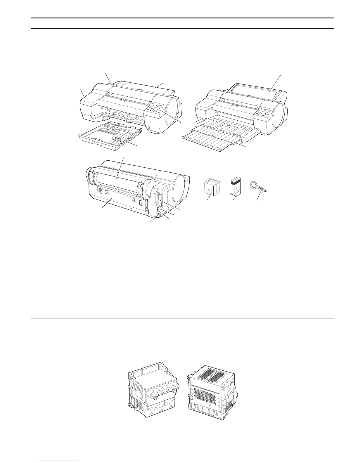
1.1.1 Product Overview
This printer is capable of printing on A4- to A2-size cut sheets and its maximum print width is 17 inches. This printer is a desktop large-format printer twelve-color
(dye- and pigment-based colors) printer that can be used to print office documents as well as handy POP and posters. An auto roll feed unit holder is optionally
available for printing on roll media.
[2]
[1]
[5]
[7]
0013-2854
[4]
[3]
[6]
[8]
[9]
[13]
[14] [15] [16]
[12]
[10]
[1] Top Cover [10] Power Supply Connector
[2] Ink Tank Cover [11] Ethernet Connector
[3] Cassette [12] USB Port
[4] Operation Panel [13] IEEE1394 Board(option)
[5] Paper Tray Unit [14] Printhead
[6] Output Stacker [15] Ink Tank
[7] Auto Roll Feed Unit(option) [16] Cleaning Brush
[8] Roll Horder Set(option)
[9] Back Cover
[11]
F-1-1
T-1-1
1.2 Features
1.2.1 Printhead
Printhead set on the carriage is a 6-color integral disposable type.
On the printhead, two rows of 1,280 nozzles (total 2,560 nozzles) are arranged in a staggered pattern. .
If print quality does not improve despite carrying out the specified cleaning, the printhead must be replaced with a new one. Generally, it is recommended that the
printhead be replaced about 12 months after you have opened the package.
0012-6187
F-1-2
1-1
Chapter 1
1.2.2 Ink Tank
The ink tank is disposable.
There are twelve pigment-based ink colors (matte black,black,photo cyan,cyan,photo magenta,magenta,yellow,red,blue,green,gray,and photo gray).
This printer features a mechanism by which only the correct color ink tank will fit in the given slot.
When the message No Ink is displayed, replace the ink tank with a new one. Also, each ink tank should generally be replaced six months after you have opened the
0013-0608
package.
F-1-3
1.2.3 Cutter
A round-blade cuter comes with the cutter unit.
F-1-4
0013-3524
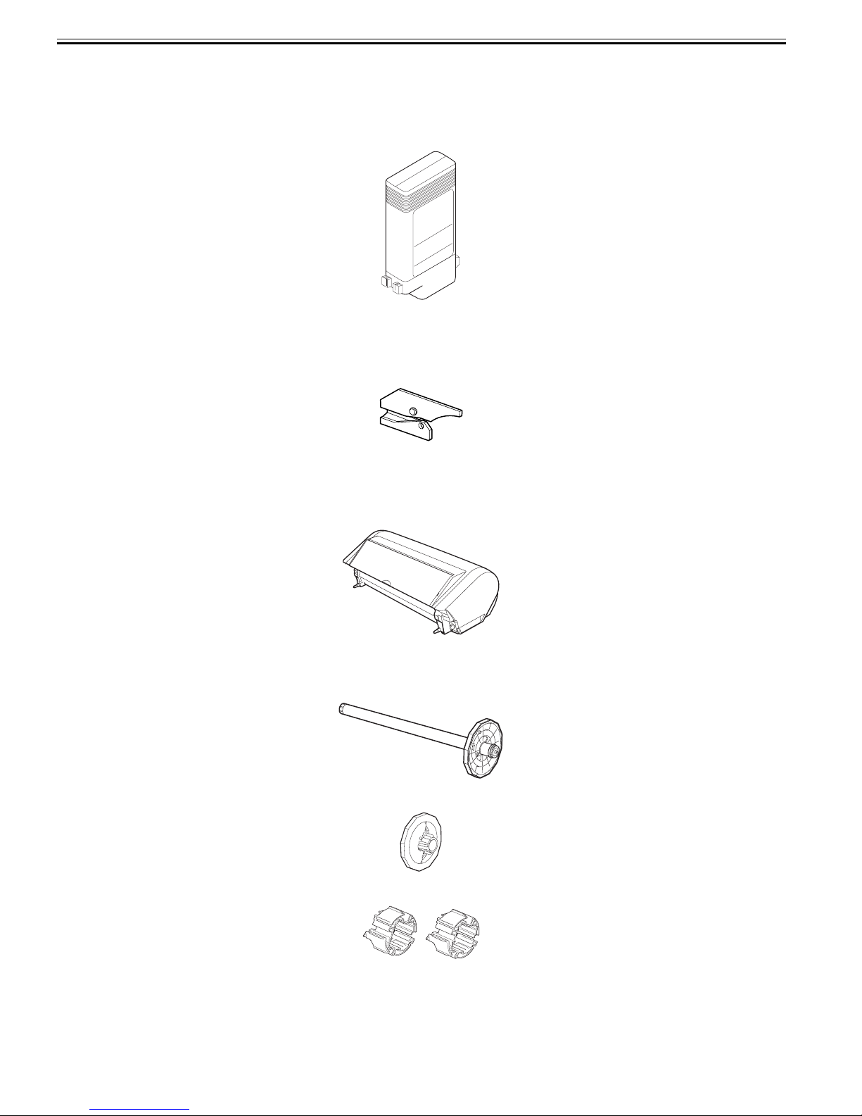
1.2.4 Auto Roll Feed Unit
Auto Roll Feed Unit (option)
The auto roll feed unit is optionally available to use roll media with this printer.
F-1-5
0013-2356
Roll holder set (option)
This set consists of roll holder, holder stopper, 3-inch paper tube attachment (two), and borderless printing spacer (commonly used for 2-inch paper tube and 3-inch
paper tube).
[Roll holder]
F-1-6
[Holder stopper]
[3-inch paper tube attachment](2 pcs.)
F-1-7
[Borderless printing spacer]
1-2
F-1-8
F-1-9
Chapter 1
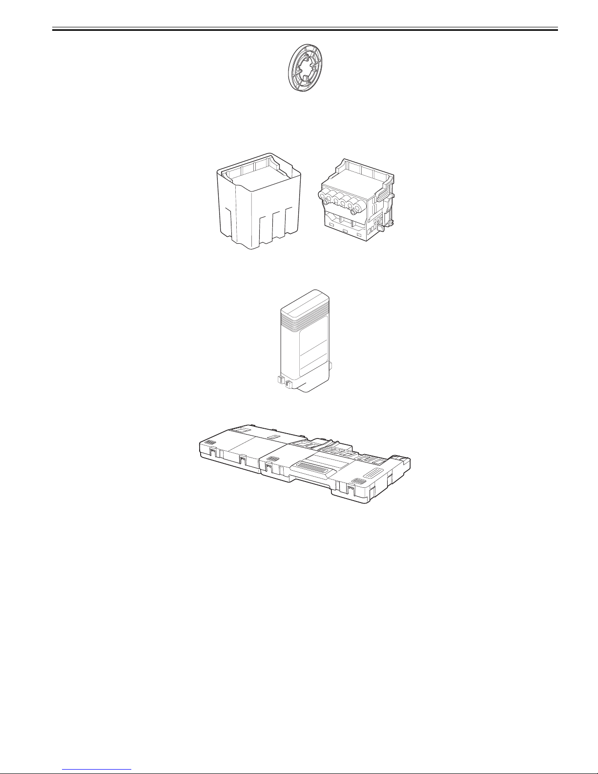
1.2.5 Consumables
Printhead
0013-0609
The consumable print head is the same as that supplied with the printer.
Ink Tanks
F-1-10
The consumable ink tanks are available in twelve colors (matte black, black, photo cyan, cyan, photo magenta, magenta, yellow, red, blue, green, photo gray, and
gray). They are the same as those supplied with the printer. Each ink tank must be replaced with a new one six month after you have opened the package.
Maintenance cartridge
The consumable maintenance cartridge is the same as that supplied with the printer.
F-1-11
F-1-12
1-3

Chapter 1
1.3 Product Specifications
1.3.1 Product Specifications
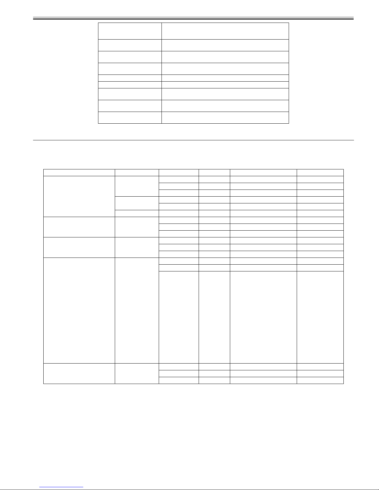
Type Bubble jet large-sized paper printer
Feeding system Automatic feeding of one roll media (option)/Cassette paper feeding/
Feeding capacity - Roll media (option)
Delivery method Delivers the media with its printed side up in the forward direction.
Sheet delivery capability - Roll media (option)
Cutter Automatically cuts paper laterally. Cartridge-type (with round blade)
Type of media Plain paper, plain paper (high quality), plain paper (vivid color), coated
Supported thickness Roll media: 0.07 to 0.8 mm
Media size (Roll media) Maximum size: 432 mm x 18 m
Media size (Cut sheet) - Manual feed from top
One cut sheet (manual feed from front)/One cut sheet (manual feed from
top)
One roll at the back/Outer diameter of roll: 150 mm or less/Inner
diameter of paper tube: 2 or 3 inches
-Cut sheet
Cassette:250 sheets(A4), 100 sheets(A3), 50 sheets(A2)
1 sheet
- Cut sheet
50 sheets (plain paper of A3 or smaller) or 20 sheets (plain paper of larger
than A3)
paper, extra heavy coated paper, premium matte paper, high-quality
dedicated paper, matte photo paper, photo glossy paper, photo semiglossy paper, photo glossy paper (heavy), photo semi-glossy paper
(heavy), professional photo paper, super photo paper, super photo paper
(silky), glossy paper, synthetic paper, adhesive synthetic paper, proofing
paper, newspaper proofing paper, tracing paper (CAD), semi-translucent
matte film (CAD), POP board
Cassette: 0.08 to 0.3 mm
Manual feed from top: 0.08 to 0.5 mm
Manual feed from front: 0.5 to 1.5 mm
Minimum size: 203.2 mm x 203.2 mm
Maximum outside diameter: 150 mm
Maximum size: 432 mm x 609.6 mm (W x L)
Minimum size: 203.2 mm x 279 mm (W x L)
- Manual feed from front
Maximum size: 432 mm x 609.6 mm (W x L)
Minimum size: 203.2 mm x 520 mm (W x L)
0013-0610
Printable area (Roll media) Area excluding 3mm from the top, 3 mm from the bottom, and 3 mm
Printable area (Cut sheet) Area excluding 3 mm from the top, 23 mm from the bottom (3 mm when
Printing assurance area (Roll
media)
Printing assurance area (Cut
sheet)
Interface USB2.0, Ethernet, IEEE1394 (option)
Printhead/Ink Tank type Printhead and separate ink tanks
Printhead [PF-01] Number nozzles: 2560 nozzles per color
Ink tank [PFI-102]MBK,BK,GY,PGY,R,G,B,C,M,Y,PC,PM
Detection functions (Cover
system)
Detection functions (Ink passage
system)
Detection functions (Carriage
system)
from the left and right edges.
Borderless printing: 0 mm from the top, bottom, and left and right edges.
Width of media allowing borderless printing:10inches, JIS B4, A3+,
14inches, 16inches, 17inches, ISO A2/A3
Media type allowing borderless printing:Coated paper (heavy), photo
glossy paper, photo semi-glossy paper, photo glossy paper (heavy),
photo semi-glossy paper (heavy), photo glossy paper, photo semi-glossy
paper, fine art (photo), fine art (photo heavy), fine art (painting),
premium matte, fine art (watercolor), fine art (block print)
supplied from the cassette), and 3 mm from the left and right edges.
Printing assurance area (Roll sheet)
Area excluding 20 mm from top, 20 mm from the bottom and 5 mm from
the left and right edges (standard size).
Printing assurance area (cut sheet)
Area excluding 20 mm from the top, 23 mm from the bottom (20 mm
when fed from the cassette), and 5 mm from the left and right edges
(standard size).
Capacity: 130 ml per color (Ink tanks supplied with the printer contain
90 ml of each color.)
Detects opening/closing of the top cover and ink cover.
Detects presence/absence of ink tank, ink level, presence/absence of the
maintenance cartridge, waste ink full level, presence/absence of the
printhead, and opening/closing of the supply valve.
Detects the ambient temperature, head temperature, presence/absence of
the head, and no ink ejection.
1-4
Chapter 1
Detection functions (Paper path
system)
Operating noise During printing: Approx. 53 dB (A) or less
Operating environment Temperature: 15 oC to 30oC
Print quality guaranteed
environment
Power supply 100-120 VAC (50/60 Hz), 220-240 VAC (50/60 Hz)
Power consumption (Maximum) During printing: Max. 100 W
Power consumption In power save (sleep) mode: 6 W or less(220-240 VAC: 7W or less)
Printer unit dimensions
(WxDxH)
Weight Without roll media unit (option): Approx. 45 kg
1.4 Detailed Specifications
1.4.1 Printing Speed and Direction
Media Type Print Priority Print Quality Print-pass Printing direction(*1) Print resolution
Plain Paper
Plain Paper(High Quality)
Plain Paper(High Grade)
High Resolution Paper
Coated Paper
Heavyweight Coated Paper
Premium Matte Paper
Matte Photo Paper
Glossy Photo Paper
Semi-Glossy Photo Paper
Heavyweight Glossy Photo Paper
Heavyweight SemiGlos Photo Paper
Glossy Paper
Photo Paper Plus
Photo Paper Plus Semi-Glos
Synthetic Paper
Adhesive Synthetic Paper
Backlit Film
Backprint Film
Thin Fabric Banner 2
Proofing Paper
Fine Art Photo
Fine Art Heavyweight Photo
Fine Art Textured
Fine Art Watercolor
Fine Art Block Print
Canvas Matte 2
Japanese Paper Washi
POP Board
CAD Tracing Paper
CAD Tranclucent Matte Film
Image Draft 2-pass Bi-directional 1200x1200dpi
Line Drawing/
Text
Office Document Standard 4-pass Bi-directional 1200x1200dpi
Image Standard 4-pass Bi-directional 1200x1200dpi
Image Standard 6-pass Bi-directional 1200x1200dpi
Image Standard 6-pass Bi-directional 1200x1200dpi
Line Drawing/
Text
Detects presence/absence of paper, remaining paper, cutter position,
presence/absence of the cassette, leading/trailing edge of paper, paper
width, and skew.
During standby: Approx. 35 dB (A) or less
Humidity: 10% to 80% without dew condensation
Temperature: 15 oC to 30oC
Humidity: 10% to 80%RH
During standby: 1 W or less
Without roll media unit (option): 999 x 733 x 317 mm
With roll media unit (option): 999 x 810 x 344 mm
With roll media unit (option): 49 kg
T-1-2
Standard 4-pass Bi-directional 1200x1200dpi
High 8-pass Bi-directional 1200x1200dpi
Draft 2-pass Bi-directional 1200x1200dpi
Standard 4-pass Bi-directional 1200x1200dpi
High 8-pass Bi-directional 1200x1200dpi
Highest 12-pass Bi-directional 2400x1200dpi
High 8-pass Bi-directional 2400x1200dpi
Highest 16-pass Bi-directional 2400x1200dpi
High 8-pass Bi-directional 2400x1200dpi
Highest
16-pass Bi-directional 2400x1200dpi
Draft 2-pass Bi-directional 1200x1200dpi
Standard 4-pass Bi-directional 1200x1200dpi
High 8-pass Bi-directional 2400x1200dpi
0013-3710
*1 The print engine may automatically select 1-way printing depending on the printing image type (graphic image, etc.). The printing direction can be selected
using the printer driver.
1.4.2 Interface Specifications
a. USB (standard)
(1) Interface type
USB 2.0, Full speed (12 Mbits/sec), High speed (480 Mbits/sec)
(2) Data transfer system
Control transfer
Bulk transfer
(3) Signal level
Compliant with the USB standard.
(4) Interface cable
0012-6200
1-5

Chapter 1
Twisted-pair shielded cable, 5.0 m max.
Compliant with the USB standard.
Wire materials: AWG No.28, data wire pair (AWF: American Wire Gauge)
AWG No.20 to No.28, power distribution wire pair
(5) Interface connector
Printer side: Series B receptacle compliant with USB standard
Cable side: Series B plug compliant with USB standard
b. Network (standard)
(1) Interface type
Interface compliant with IEEE802.3
(2) Data transfer system
10Base-T/100Base-TX
(3) Signal level
Input: Threshold
10Base-T: Max. +585 mV, Min. +300 mV
100Base-TX: Turn-on +1000 mV diff pk-pk, Turn-off +200 mV diff pk-pk
Output:
10Base-T: +2.2 V to +2.8 V
100Base-TX: +0.95 to +1.05 V
(4) Interface cable
Category 5 (UTP or FTP) cable, 100 m or shorter
Compliant with ANSI/EIA/TIA-568A or ANSI/EIA/TIA-568B
(5) Interface connector
Printer side: Compliant with IEEE802.3, ANSI X3.263, ISO/IEC60603-7
c. IEEE1394 (option)
(1) Interface type
Interface compliant with IEEE1394-1995, P1394a (Version 2.0)
(2) Data transfer system
Asynchronous transfer
(3) Signal level
Input:
Differential input voltage:
During S100 settlement: +173 mV to +260 mV
During data reception: +142 mV to +260 mV
During S200 settlement: +171 mV to +262 mV
During data reception: +132 mV to +260 mV
During S400 settlement: +168 mV to +265 mV
During data reception: +118 mV to +260 mV
Output:
Differential output voltage: +172 mV to +265 mV
(4) Interface cable
Twisted-pair shielded cable, 4.5 m max.
Compliant with IEEE1394-1995 standard or P1394a (Version 2.0) standard
(5) Interface connector
Printer side: 6-pin connector (socket) compliant with IEEE1394 standard
Cable side: 6-pin connector (plug) compliant with IEEE1394 standard
Cable side: RJ-45 type compliant with ANSI/EIA/TIA-568A or ANSI/EIA/TIA-568B
1-6
1.5 Names and Functions of Components
Chapter 1
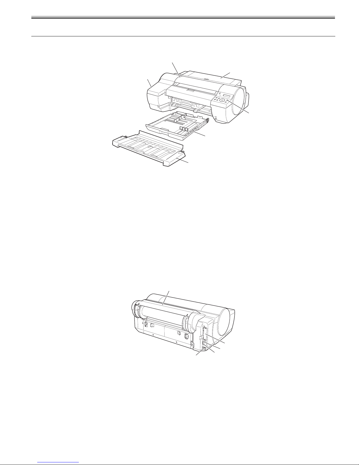
1.5.1 Front
[1]
[2]
[3]
[6]
F-1-13
[1] Top cover
Open this cover when installing the printhead or remove the paper jammed inside the printer.
[2] Ink tank cover
Open this cover when replacing ink tanks.
[3] Cassette
Load paper in this tray
[4] Operation panel
This panel includes the Power button, Online button, and display.
[5] Paper tray unit
This is a standard unit used to feed cut sheets manually.
It can be replaced with the optional auto roll feed unit.
[6] Output tray
The ejected prints are stacked in this tray.
0012-6334
[5]
[4]
1.5.2 Rear
[1] Auto roll feed unit (option)
Load cut sheets or roll media in this unit.
[2] Power connector
Connect the power cord to this connector.
[3] USB port
Connect the USB cable to this port.
[4] Ethernet connector
Connect the Ethernet cable to this connector.
[5] Expansion board slot
Insert the IEEE1394 board (option) in this slot.
[1]
F-1-14
[2]
0012-6336
[5]
[4]
[3]
1-7
Chapter 1
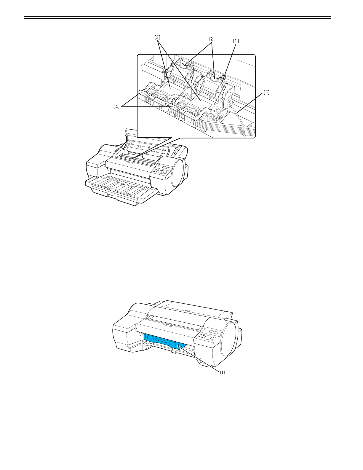
1.5.3 Carriage
0013-3730
[1] Carriage
[2] Printhead lock cover
This cover is used to lock the printhead. Open this cover when installing the printhead.
[3] Printhead
The printhead incorporated nozzles. It is an important part for printing.
[4] Printhead lock lever
This lever is used to lock the printhead. Open this lever when installing the printhead.
[5] Ink tube guide
This stay is used as an ink tube guide.
1.5.4 Inside
[1] Maintenance cartridge
F-1-15
0012-6340
F-1-16
1-8
1.6 Basic Operation
Chapter 1
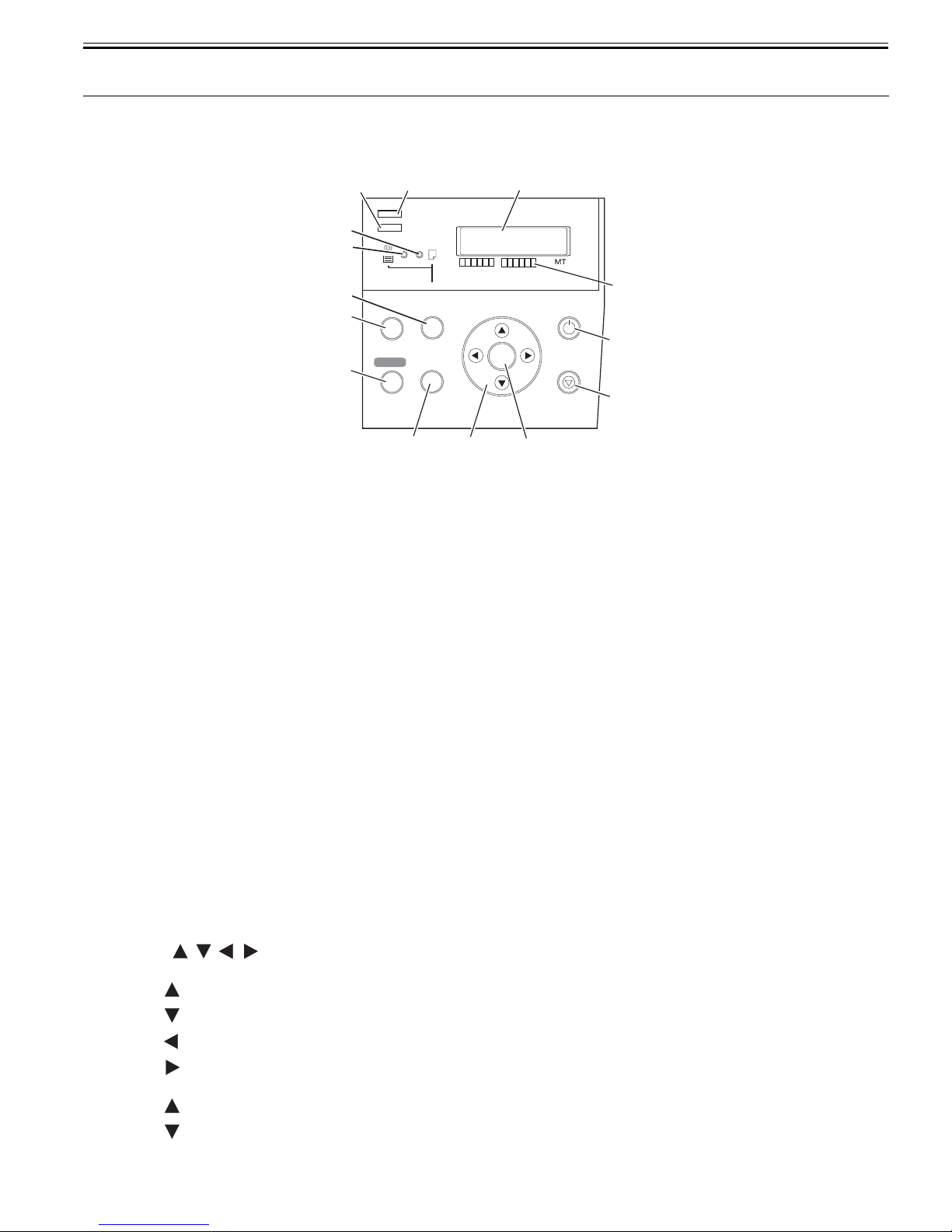
1.6.1 Operation Panel
This section explains the functions of the buttons and the meanings of the LEDs on the operation panel.
[3] [2]
Data
[4]
Message
[5]
Auto Feed
[6]
[7]
[8]
Online
Menu
Feeder
Selection
Information
Cleaning
(3 Sec.)
[10][9]
[1] Display
This display shows the printer menus, statues, and messages.
[2] Data lamp (green)
Flashing: When the printer is printing, this lamp indicates that the printer is receiving or processing a print job.
When the printer is not printing, this lamp indicates that the print job is paused or firmware data is being received.
Off: This indicates that there is no print job.
[3] Message lamp (orange)
On: This indicates that a warning message is displayed.
Flashing: This indicates that an error message is displayed.
Off: This indicates that the printer is normal or the power is turned off.
[4] Auto Feed lamp (green)
On: This indicates that the cassette or roll media is selected as the paper source.
Off: This indicates that the paper tray or thick paper feed slot is selected as the paper source.
[5] Paper Tray lamp (green)
On: This indicates that the paper tray or thick paper feed slot is selected as the paper source.
Off: This indicates that the cassette or roll media is selected as the paper source.
[6] Paper Source button
This button is used to select a paper source. Pressing this button toggles between the automatic pickup and manual feed.
The [Auto Feed] lamp or [Paper Tray] lamp goes on.
[7] Online button
This button switches between online and offline modes.
On: This indicates that the printer is in the online status.
Off: This indicates that the printer is in the offline mode.
[8] Menu button
This button displays the main menu of the printer.
[9] Information button
This button displays a submenu. Information about the ink and media each time you press this button.
Head cleaning is carried out when this button is held pressed for at least 3 seconds.
F-1-17
OK
[1]
[11]
Powe r
Stop/Eject
(1 Sec.)
0013-0043
[14]
[13]
[12]
[10] buttons
(In the menu mode)
button: Displays the next higher-level menu.
button: Displays the next lower-level menu.
button: Displays the previous item or setting.
button: Displays the next item or setting.
(In the offline mode)
button: Feeds the roll media in the reverse direction.
button: Feeds the roll media in the normal direction.
[11] OK button
1-9

Chapter 1
This button sets or executes the selected operation or value.
[12] Stop/Eject button
This button aborts the job in progress and ejects the media.
[13] Power button
This button turns on/off the printer.
[14] Color label
This label indicates the ink tank colors and names that correspond to the ink level indications shown on the display.
1.6.2 Printer Stats Transition
The following chart shows various printer states and how they are transited by button operations.
INITIALIZING
ONLINE PRINTING
MAIN MENU
OFFLINE
Key operations
and print commands
SLEEP SUB MENU
1 Sec.
SHUTDOWN
F-1-18
PAUSE
Auto
Online Key
Menu Key
Infomation Key
Powe r Key
0012-6208
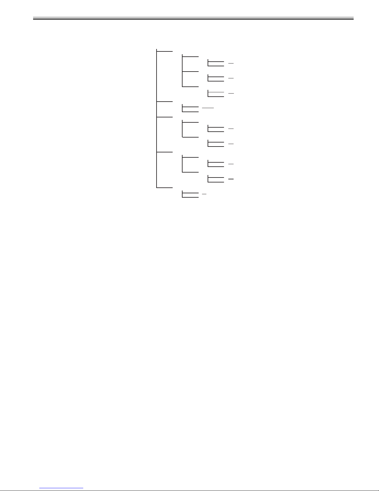
1.6.3 Main Menu
The printer has a Main menu which includes a menu related to maintenance such as adjustment of ink ejection position of each nozzle and head cleaning, a menu
related to printing settings such as auto cutting and ink drying time, and a menu related to parameters such as a message language.
a. Main menu operations
(1) How to enter the Main menu
0013-3512
To enter the Main menu, press the [Menu] button on the operation panel.
(2) How to exit the Main menu
To exit the Main menu, press the [Online] button.
(3) Buttons used with the Main menu
- Selecting menus and parameters: [ ] or [ ] button
- Going to the next lower-level menu: [ ] button
- Going to the next higher-level menu: [ ] button
- Determining a selected menu or parameter: [OK] button
2. Main Menu
Hierarchical levels and parameters of the Main menu are shown below.
1-10

MAIN MENU
Head Cleaning *1
Force Cutting *2
Paper Settings
Med.Detail Set.
Adjust Printer Refer to "Printing adjustment menu"
Interface Setup Refer to "Interface setup menu"
Maintenance
System Setup Refer to "System setup menu"
Test Print
Adjust Band *4
Information Refer to "Information menu"*1
Head Cleaning A
Head Cleaning B
No
Yes
Cas Paper Type
Cas Paper Size
Tray Paper Type
Roll Media Type *2
Chk Remain.Roll *3
On
Off
Roll Length Set
##.# m
### feet
Media Type
Replace P.head
Left Printhead
Right Printhead
Move Printer
No
Yes
Clean Roller
No
Yes
Clean Platen
No
Yes
Status Print
Media Details
Print Job Log
Menu Map
Nozzle Check
-3
3
Refer to "Media detail setup menu"
No
Yes
No
Yes
Chapter 1
*1 Displayed even when printing
*2 Displayed only when roll media is loaded
*3 Displayed only when Auto Roll Feed Unit is attached
*4 Displayed only during printing
F-1-19
1-11

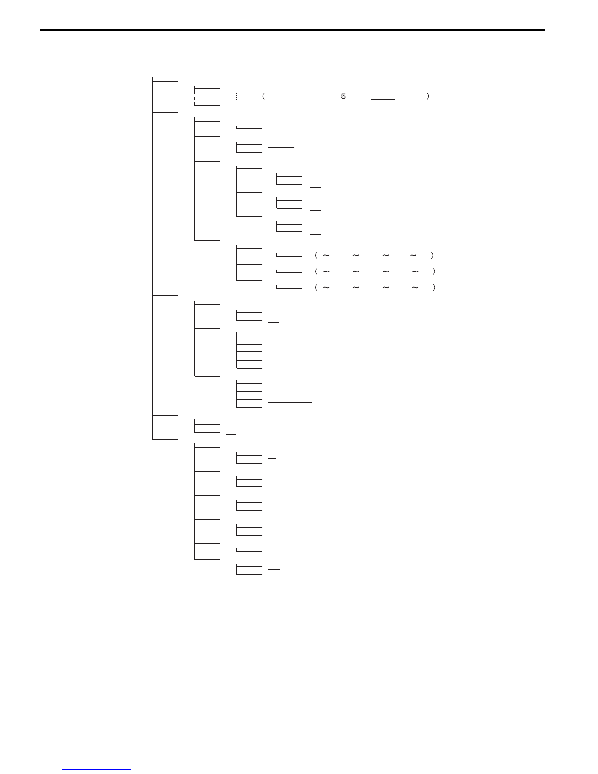
Chapter 1
Media detail setup menu
Med.Detail Set.
Media type
Roll DryingTime
Off
30 sec.,1 min.,3 min.,5 min.,10 min.,30 min.
60 min.
Scan Wait Time
Off
1 sec.,3 sec.,5 sec.,7 sec.
9 sec.
Feed Priority
Automatic
Band Joint
Print Length
Adjust Length
-0.70%
0.00%
0.70%
Head Height
Automatic
Lowest
Low
Standard
High
Highest
Skew Check Lv.
Standard
Off
Loose
VacuumStrength
Automatic
Strongest
Strong
Standard
Weak
Width Detection
On
Off
NearEnd RllMrgn
3mm
20mm
Cut Speed
Fast
Slow
Standard
Trim Edge First
Forced
No Cutting
Cutting Mode
Automatic
Eject
Manual
Bordless Margin
Automatic
Fixed
CutDustReduct
On
Off
Nr End Sht Mrgn
3mm
20mm
Tray Source
Top
Front
Return Defaults
No
Yes
F-1-20
1-12
Printing adjustment menu
Chapter 1
Adjust Printer
Auto Head Adj.
Manual Head Adj
Auto Band Adj.
Manual Band Adj
Adjust Length
Advanced Adj.
Standard Adj.
Auto Print
No
Yes
Standard Adj.
Advanced Adj.
Adjust Band
Adj Far Ed Feed
No
Yes
F-1-21
No
Yes
No
Yes
On
Off
No
Yes
No
Yes
No
Yes
No
Yes
1-13
Chapter 1
Interface setup menu
Interface Setup
EOP Timer
TCP/IP
NetWare
AppleTalk
Ethernet Driver
10 sec.
30 sec.,1 min.,2 min., min., 10 min.,30 min.
60 min.
TCP/IP
On
IP Mode
Manual
Automatic
Protocol
DHCP
BOOTP
RARP
IP Setting
IP Address
Subnet Mask
Default G/W
NetWare
On
Off
Frame Type
Auto Detect
Ethernet 2
Ethernet 802.2
Ethernet 802.3
Ethernet SNAP
Print Service
BindaryPserver
RPrinter
NDSPserver
NPrinter
On
Off
Auto Detect
On
Off
Comm.Mode
Half Duplex
Full Duplex
Ethernet Type
10 Base-T
100 Base-TX
Spanning Tree
Use
Not Use
MAC Address
( xxxxxxxxxxxx )
Init. Settings
No
Yes
*1
On
Off
On
Off
On
Off
0 255. 0 255. 0 255.0 255
0 255. 0 255. 0 255. 0 255
0 255. 0 255. 0 255. 0 255
*2
*2
*1 Displayed when "Automatic"is selected for "IP mode"
*2 Displayed when "Off"is selected for "Auto Detect"
1-14
F-1-22
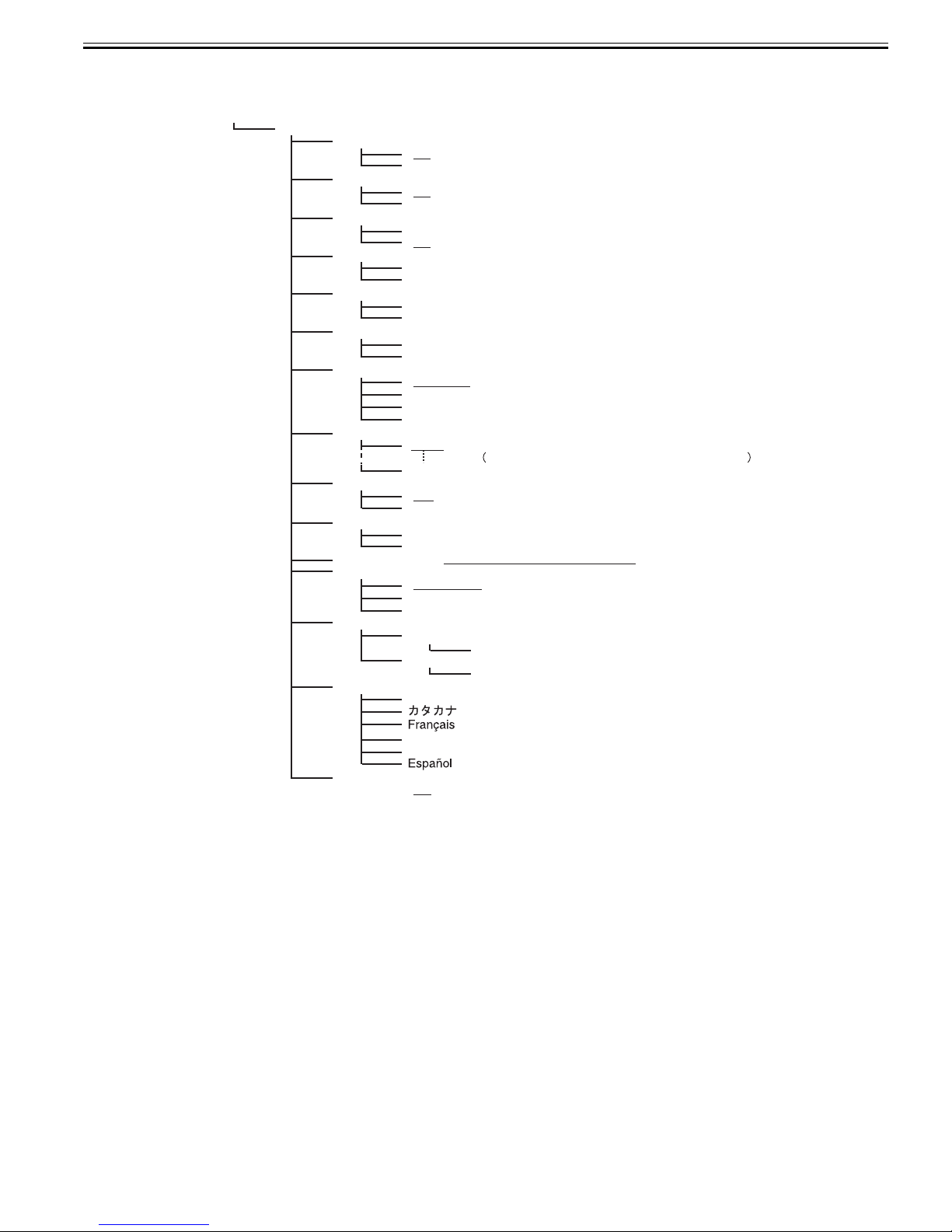
System setup menu
Chapter 1
System Setup
Warning
Buzzer
On
Off
Ignore Mismatch
On
Off
Keep Media Size
On
Off
Sht Selection
ISO A3+
ANSI B Super
Roll Selection1 *1
ISO A3 (297mm)
300mm Roll
Roll Selection2 *1
10in. (254mm)
JIS B4 (257mm)
Nozzle Check
Automatic
Off
5 pages
10 pages
Sleep Timer
5 min.
10 min.,15 min.,20 min.,30 min.,40 min.,50 min.
60 min.
Use Power Save
On
Off
Length Unit
meter
feet/inch
Time Zone Refer to "Time Zone setting menu"
Date Format
yyyy/mm/dd
dd/mm/yyyy
mm/dd/yyyy
Date & Time
Date *2
yyyy/mm/dd
Time
hh:mm
Language
English
Italiano
Deutsch
Reset MediaType *3
No
Yes
*1 Displayed only when Auto Roll Feed Unit is attached
*2 Display method depends on "Date Format"
*3 Returns settings of "Med. Detail Set" to the state of factory shipment
F-1-23
1-15

Chapter 1
Time Zone setting menu
Time Zone
0 London (GMT)
+1
Paris , Rome
+2
Athens , Cairo
+3
Moscow
Eerevan , Baku
+4
Islamabad
+5
+6
Dacca
Bangkok
+7
Hong Kong
+8
+9
Tokyo , Seoul
Canbera
+10
NewCaledonia
+11
Wellington
+12
-12
Eniwetok
Midway Is.
-11
Hawaii (AHST)
-10
Alaska (AKST)
-9
Oregon (PST)
-8
-7
Arizona (MST)
Texas (CST)
-6
New York (EST)
-5
Santiago
-4
-3
Buenos Aires
-2
-1 Cape Verde
Meaning of code address
GMT Greenwich Mean Time
AHST Alaska-Hawaii Std Time
AKST Alaska Standard Time
PST Pacific Std Time
MST Mountain Standard Time
CST Central Std Time
EST Eastern Standard Time
:
:
:
:
:
:
:
F-1-24
Information menu
Information
Version
RAM
Ext. Interface
MAC Address
Error Log
Job Log
Counter
Firm
##.##
Boot
##.##
### MB
Disable
IEEE1394
000085######
########
1
########
2
Job Log No.1
Job Log No.2
Job Log No.3
Cut Count
F-1-25
Document Name
User Name
Page Count
Job Status
Print Start Time
Print End Time
Print Time
Print Size
Media Type
Interface
Ink Consumption
#
1-16
 Loading...