

Page 1

-
Operating
Information
Page 2

Copyright
Copyright 2011 by Canon Inc. All rights reserved.
No part of this publication may be reproduced or transmitted in any form or by any means,
electronic or mechanical, including photocopying and recording, or by any information
storage or retrieval system without the prior written permission of Canon Inc.
© 2011, Océ
All rights reserved. No part of this work may be reproduced, copied, adapted, or transmitted
in any form or by any means without written permission from Océ.
Océ makes no representation or warranties with respect to the contents hereof and specifically disclaims any implied warranties of merchantability or fitness for any particular purpose.
Furthermore, Océ reserves the right to revise this publication and to make changes from
time to time in the content hereof without obligation to notify any person of such revision
or changes.
Edition: 07-2011
Page 3

Contents
Contents
Chapter 1
Preface.................................................................................................................9
Trademarks...............................................................................................10
Copyright...................................................................................................11
Notes for the reader.................................................................................12
Abbreviations used in this manual.........................................................14
Available documentation.........................................................................15
Chapter 2
Main parts..........................................................................................................17
Overview of the machine configuration.................................................18
The main unit............................................................................................22
The paper modules..................................................................................26
The tab feeder (optional).........................................................................31
The special feeder (optional)...................................................................33
The automatic document feeder - ADF (optional).................................35
The color scanner (optional)...................................................................37
The operator panel...................................................................................38
The operator attention light....................................................................42
Finishing options......................................................................................44
The stacker/stapler, optional inserter and optional integrated punch
unit.............................................................................................................45
The puncher..............................................................................................56
Chapter 3
Operating concept............................................................................................59
Operating concept....................................................................................60
Access the Settings Editor ......................................................................64
Maintain the 'Media catalog' ..................................................................66
Maintain the 'Media families' .................................................................68
Maintain the 'Color pre-sets' ..................................................................70
Maintain the 'Input profiles' ...................................................................72
Maintain the 'Output profiles' ................................................................73
Maintain the 'Spot colors' ......................................................................74
Prepare print jobs with PRISMAprepare ...............................................75
Prepare print jobs with the printer driver...............................................77
Manage production printing...................................................................80
Chapter 4
Operator panel views.......................................................................................83
The dashboard..........................................................................................84
3
Page 4

Contents
The 'Schedule' view.................................................................................86
The 'Jobs' view.........................................................................................88
The 'Trays' view.......................................................................................90
The 'System' view....................................................................................91
Chapter 5
Power information............................................................................................93
The power buttons and power modes...................................................94
Turn on the controller..............................................................................96
Turn on the printer...................................................................................98
Turn off the printer...................................................................................99
Use the Sleep mode...............................................................................100
Chapter 6
Print jobs..........................................................................................................101
General information...............................................................................102
Introduction to the print function....................................................102
Description of the print job settings...............................................104
Contradiction handling....................................................................119
Manage print jobs..................................................................................120
Print an urgent job immediately.....................................................120
Give priority to a print job...............................................................121
Print a scheduled job later...............................................................122
Reprint a job......................................................................................123
Print a job ticket................................................................................125
Make a proof.....................................................................................126
Stop the printer.................................................................................127
Delete print jobs...............................................................................129
Schedule a waiting job for printing................................................131
Select more than one job for printing............................................132
Print a file from a USB drive............................................................133
Media handling.......................................................................................134
Introduction to the 'Schedule' view................................................134
Load the media using the 'Schedule' view....................................138
Description of the 'Trays' view........................................................140
Load the media using the 'Trays' view...........................................143
Introduction to the 'Media' section.................................................145
Introduction to the media handling................................................147
Add temporary media to the 'Media catalog' ...............................149
Correct skewed and rotated images...............................................150
Perform a media registration..........................................................152
Change the job settings before printing...............................................154
Change the number of sets.............................................................154
Check the first set.............................................................................155
Change the use of separator sheets...............................................157
4
Page 5

Contents
Stack the prints with an offset.........................................................158
Combine jobs....................................................................................160
Change the output settings before printing.........................................162
Change '2-sided' into '1-sided' and vice versa...............................162
Change the binding edge.................................................................163
Select a different media for a job....................................................164
Change the settings for covers........................................................165
Shift the image roughly to create binding space...........................166
Shift the image precisely to create binding space or correct the lay-
out......................................................................................................167
Change the print delivery settings..................................................169
Change the finishing method..........................................................171
Chapter 7
Copy jobs.........................................................................................................173
General information...............................................................................174
Introduction to the copy function....................................................174
Description of the copy job settings...............................................176
Feed originals to the ADF (optional)...............................................193
Feed originals to the SADF (optional).............................................196
Put originals on the glass plate.......................................................198
Clean the glass plate........................................................................200
Copy your documents............................................................................202
Make a copy......................................................................................202
Combine subsets into 1 document.................................................203
Access other functions during a copy job or scan job..................204
The zoom behavior...........................................................................205
Create and use custom copy templates.........................................208
Rename a copy job...........................................................................209
Copy non-standard size originals....................................................210
Scan now and print later (postponed copying).............................211
Finish the output...............................................................................212
Adjust the image to improve the copy and scan quality..............213
Chapter 8
Scan jobs.........................................................................................................215
Introduction to the scan function..........................................................216
Description of the scan job settings.....................................................218
Scan to file..............................................................................................225
Scan to USB............................................................................................226
Combine subsets into one file...............................................................227
Chapter 9
Paper, toner, and staples...............................................................................231
Paper........................................................................................................232
Load the media into the paper tray.................................................232
5
Page 6

Contents
Adjust the paper tray to hold a different media size.....................240
Load the media into the bulk media module (optional)................245
Adjust the media size for the bulk media module (optional)........252
Adjust the outer size change plate of the bulk paper module (option-
al).......................................................................................................261
Load the media into the special feeder (optional).........................268
Load tabs via the tab feeder (optional)...........................................272
Adjust the media size of the tab feeder (optional).........................279
Load the required media into the selected tray.............................282
Check the status of the punch waste box.......................................289
Removing the punch waste.............................................................290
Toner.......................................................................................................293
Check the status of the toner reservoir and waste toner container.293
Replacing the toner cartridge..........................................................295
Replacing the waste toner container..............................................301
Staples.....................................................................................................304
Check the status of the staple cartridges........................................304
Replacing the staple cartridge in the stapler unit..........................306
Replacing the staple cartridge in the saddle stitcher unit.............310
Chapter 10
Adapt printer settings to your needs............................................................315
System settings (access through the operator panel)........................316
Introduction to the 'Setup' section..................................................316
Work with the workflow profiles.....................................................318
Change the warning time................................................................322
Disable the warning time.................................................................323
Truncate the job name.....................................................................324
Adjust the brightness and contrast of the operator panel............325
Access Settings Editor settings via the operator panel.................326
Automated workflows (access through the Settings Editor)..............329
Introduction to automated workflows............................................329
Add an automated workflow...........................................................331
Edit an automated workflow...........................................................332
Delete an automated workflow.......................................................333
Restore the factory default workflow..............................................334
Hotfolders................................................................................................335
Introduction to hotfolders................................................................335
Activate the hotfolder function........................................................336
Create a hotfolder.............................................................................337
Create a shared network folder on a workstation..........................338
Create a hotfolder default ticket ('default_ticket.jdf').....................340
Chapter 11
Maintenance and calibration.........................................................................341
6
Page 7

Contents
Maintenance...........................................................................................342
Introduction to the 'Maintenance' section......................................342
Reset the day counters.....................................................................344
Find the meter readings (counters).................................................345
'Auto color mismatch correction' ...................................................346
Clean the automatic document feeder rollers................................347
Clean the roller (main unit)..............................................................348
Clean the wire...................................................................................349
Handle paper jams...........................................................................350
'Refresh the fixing roller' ................................................................351
Engine maintenance (trained operators)........................................353
Calibration...............................................................................................354
Introduction to printer calibration...................................................354
Calibrate the printer - '1. Shading correction' ...............................355
Calibrate the printer - '2. Auto gradation adjustment' .................357
Calibrate the controller - '3. Media family calibration' .................359
Adjust the CMYK calibration curve manually................................361
Chapter 12
Specifications..................................................................................................363
Specifications.........................................................................................364
Chapter 13
Third-Party Software......................................................................................383
Third Party Software..............................................................................384
The Software Subjected to the Other Conditions................................386
FPU Emulation code ..............................................................................387
Library for SDE Compiler ......................................................................389
7
Page 8

Contents
8
Page 9

Chapter 1 Preface
Page 10

Trademarks
Trademarks
List of trademarks
Océ, Océ PRISMA, Océ PRISMAsync, Océ PRISMAprepare and Océ PRISMAaccess
are registered trademarks of Océ.
Canon and imagePRESS are registered trademarks of Canon Corporation.
Adobe, Acrobat, Reader and Distiller are registered trademarks of Adobe Systems Incorporated.
PostScript 3® is a registered trademark of Adobe Systems Incorporated.
Microsoft, Windows , Windows NT, Windows 98, Windows 2000, Windows XP,
Windows Server 2003 are either registered trademarks or trademarks of Microsoft Corporation in the United States and/or other countries.
Products in this publication are referred to by their general trade names. In most, if not
all cases, these designations are claimed as trademarks or registered trademarks of their
respective companies.
PANTONE® Colors displayed in the software application or in the user documentation
may not match PANTONE-identified standards. Consult current PANTONE Color
Publications for accurate color. PANTONE® and other Pantone, Inc. trademarks are
the property of Pantone, Inc. © Pantone, Inc., 2007
Pantone, Inc. is the copyright owner of color data and/or software which are licensed to
(insert name of your company) to distribute for use only in combination with (insert
appropriate name of Licensed Materials). PANTONE Color Data and/or Software shall
not be copied onto another disk or into memory unless as part of the execution of (insert
appropriate name of Licensed Materials).
This product contains the Universal Font Scaling Technology or UFST® under license
from Monotype Imaging, Inc. UFST® is a trademark of Monotype Imaging, Inc. registered in the United States Patent and Trademark Office and may be registered in certain
jurisdictions.
Copyright © 1989 - 1996, 1997, 2003, 2004, 2008, all rights reserved, by Monotype
Imaging Inc.
Chapter 1 - Preface10
Page 11

Copyright
This product includes software and/or software modules that are licensed by Canon Inc.
or its licensors from third parties. Use and distribution of this software and/or software
modules are subject to conditions (a) through (d) below.
(a)
Copyright (C) 1999, 2000, 2002 Aladdin Enterprises. All rights reserved.
(b)
Copyright © Unpublished Work of Novell, Inc.
All Rights Reserved
(c)
Copyright©1992,1993
The Regents of the University of California. All rights reserved.
This code is derived from software contributed to Berkeley by Ralph Campbell.
(d)
•
1/4 University of California, Berkeley
Copyright (c) 1990 The Regents of the University of California.
All rights reserved.
•
2/4 David M. Gay at AT&T
The author of this software is David M. Gay.
Copyright (c) 1991 by AT&T.
•
3/4 Sun Microsystems
Copyright (C) 1993 by Sun Microsystems, Inc. All rights reserved.
•
4/4 Cygnus Solutions
Copyright (c) 1994, 1997 Cygnus Solutions.
All rights reserved.
Copyright
Chapter 1 - Preface 11
Page 12
Notes for the reader
Notes for the reader
Introduction
This manual helps you to use the imagePRESS C7010VPS/C6010VPS/C6010S. The
manual contains a description of the product and guidelines to use and operate the
imagePRESS C7010VPS/C6010VPS/C6010S.
Definition
Attention-Getters
Parts of this manual require your special attention. These parts can provide the following:
•
Additional general information, for example, information that is useful when you
perform a task.
•
Information to prevent personal injuries or property damage.
Symbols used in this manual
The following symbols are used in this manual to explain procedures, restrictions, handling
precautions, and instructions that should be observed for safety.
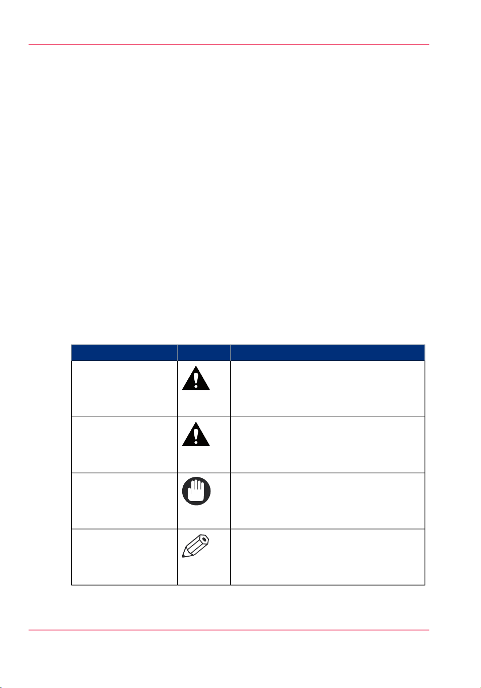
Overview of the attention-getters#
WARNING
CAUTION
IMPORTANT
NOTE
IndicatesIconWord
Indicates a warning concerning operations
that may lead to death or injury to persons if
not performed correctly. To use the machine
safely, always pay attention to these warnings.
Indicates a caution concerning operations that
may lead to injury to persons if not performed
correctly. To use the machine safely, always
pay attention to these cautions.
Indicates operational requirements and restrictions. Be sure to read these items carefully to
operate the machine correctly and to avoid
damaging the machine or property.
Indicates a clarification of an operation or
contains additional explanations for a procedure. Reading these notes is highly recommended.
Chapter 1 - Preface12
Page 13

Notes for the reader
IndicatesIconWord
Indicates an operation that must not be performed. Read these items carefully and make
sure not to perform the described operations.
Chapter 1 - Preface 13
Page 14

Abbreviations used in this manual
Abbreviations used in this manual
#
Microsoft Windows 2000:
Microsoft Windows 2000 Professional:
Microsoft Windows 2000 Server:
Microsoft Windows Server 2003:
Microsoft Windows XP:
Microsoft Windows XP Professional:
Microsoft Windows Vista operating system:
Microsoft Windows 7 operating system:
Microsoft Windows Server 2008:
Microsoft Windows operating system:
Novell NetWare:
Apple Macintosh:
Apple Mac:
Windows 2000
Windows 2000 Professional
Windows 2000 Server
Windows Server 2003
Windows XP
Windows XP Professional
Windows Vista
Windows 7
Windows Server 2008
Windows
NetWare
Macintosh
Mac
Chapter 1 - Preface14
Page 15

Available documentation
For the imagePRESS C7010VPS/C6010VPS/C6010S the following information is
available.
•
Operating information
•
Operating information for finishers
•
Operator's Maintenance Manual (English only)
•
Safety Instructions for the printer
•
Safety Information for the controller
•
Material Safety Data Sheets.
Available documentation
Chapter 1 - Preface 15
Page 16

Available documentation
Chapter 1 - Preface16
Page 17

Chapter 2 Main parts
Page 18
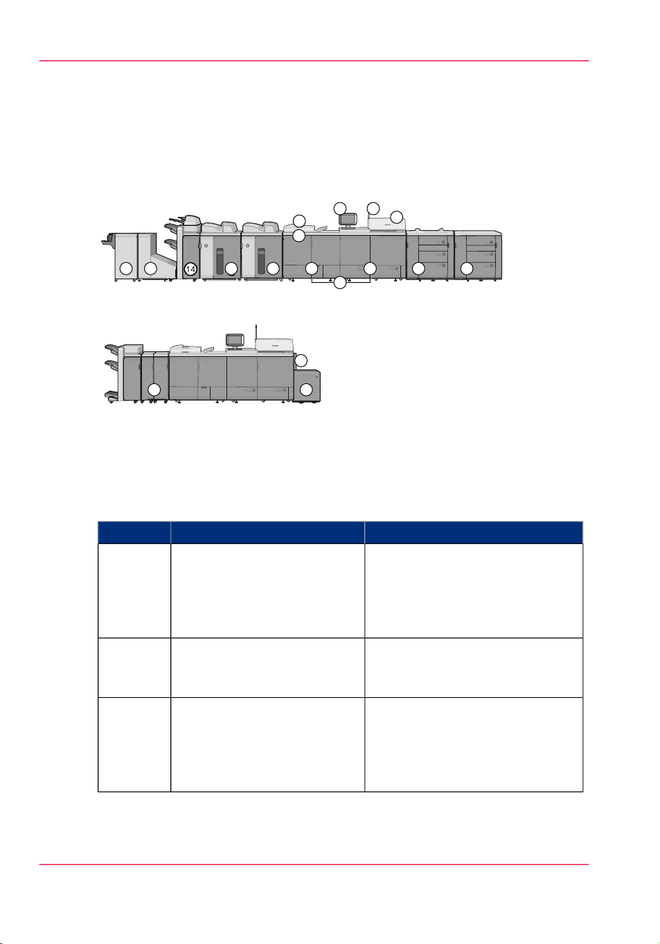
1 2
3
4
7
5
6
8 9 10
13 13
14
15
16
11
12
17
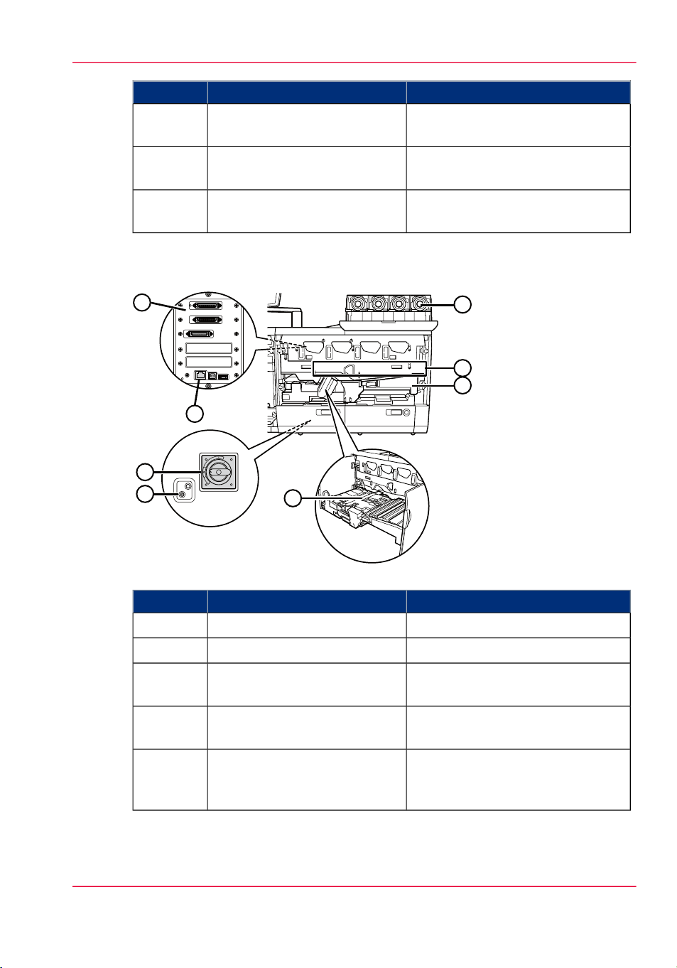
Overview of the machine configuration
Overview of the machine configuration
Introduction
The following figures display two example configurations.
[6] Mass production configuration
[7] Space saving configuration
The next section describes all available modules and options.
Main unit
#
FunctionComponent
Operator panel1
The operator panel helps you with
your daily work, for example the
scheduling of the jobs. Furthermore,
the operator panel helps you to solve
errors.
Operator attention light2
The operator attention light enables
you to check the status of the system
from a distance.
3
Color scanner and original cover
(Color Image Reader-H1 and
Platen Cover Type-K)
Optional
The color scanner is used to copy and
scan black & white and colored
originals. The original cover holds
down the original to the glass plate
of the color scanner.
Chapter 2 - Main parts18
Page 19
Overview of the machine configuration
FunctionComponent
4
Automatic Document Feeder
(Feeder DADF-R1)
Optional
The automatic document feeder is
used to copy and scan sets of 1-sided
and 2-sided documents.
Main unit5
The main unit contains the components that print the media. Access to
the main unit is only required when
a paper jam occurs or when maintenance is required.
The main unit consists of the following main parts.
•
Imaging unit (right-side)
(Marking unit)
•
Fusing unit (left-side)
(Fixing unit)
•
Power supply unit
Integrated paper trays6
The engine module contains paper
trays that contain the media that will
be printed.
Gives access to the toner bottles.Toner compartment cover7
Waste toner tray8
Gives access to the waste toner container.
#
NOTE
The spectrophotometer for calibration is not illustrated.
Optional paper modules
Input options#
9
Left-hand paper module
(POD Deck-A1)
10
Right-hand paper module
(Secondary POD-Deck-A1)
FunctionComponent
The additional paper module has
paper trays that contain the media
that will be printed.
You can add a secondary paper
module to increase the media input
capacity.
Chapter 2 - Main parts 19
Page 20

Overview of the machine configuration
11
Bulk paper module
(Paper Deck-AC1)
FunctionComponent
The bulk paper module contains the
media that will be printed. The bulk
paper module contains 1 media type.
12
Special feeder
(Stack Bypass-A1)
-
Tab feeder
(Tab Feeding Attachment-C1)
Optional finishing equipment
Output options#
13
Stacker
(High Capacity Stacker-C1)
Optional, maximum 2.
14
Stacker/stapler, optional inserter
and optional integrated punch
unit
(Finisher-AJ1 or
Saddle Finisher-AJ2 with
Document Insertion Unit-C1
and
Puncher Unit-BC1/BD1)
The special feeder is used to feed
media manually.
The tab feeder is used to load tab
paper into the paper trays.
FunctionComponent
The stacker adds output capacity to
your system. The stacker cannot staple the jobs.
The stacker/stapler offers the following functionality.
•
Stack prints
•
Staple prints
•
Create stapled booklets
•
Punch prints
With the optional inserter you can
add preprinted covers to the booklet
and sets.
15
16
17
Trimmer
(Booklet Trimmer-D1)
Two-knife trimmer
(Two-Knife Trimmer-A1)
Puncher
(Professional Puncher-B1 and
Professional Puncher Integration
Unit-A1)
The trimmer trims the long edge of
a booklet.
The two-knife trimmer trims the
short edges of a booklet.
The Professional Puncher-B1
punches several types of holes. The
Professional Puncher Integration
Unit-A1 reverses the paper punched
by the Professional Puncher-B1.
#
NOTE
Please refer to the operating information that comes with the optional finish equipment.
Chapter 2 - Main parts20
Page 21

•The operator panel, on page 38
•The operator attention light, on page 42
•The color scanner (optional), on page 37
•The automatic document feeder - ADF (optional), on page 35
•The main unit, on page 22
•The paper modules, on page 26
•The tab feeder (optional), on page 31
Overview of the machine configuration
Chapter 2 - Main parts 21
Page 22
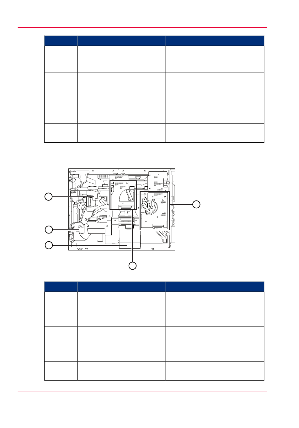
4
7
8
3
6
5
2
1
The main unit
The main unit
Introduction
This section describes and shows the main parts of the main unit.
External view
#
FunctionComponent
Operator panel1
The operator panel helps you with
your daily work, for example the
scheduling of the jobs. Furthermore,
the operator panel helps you to solve
errors.
2
Main power switch of the main
unit
3
Imaging unit
(Marking unit)
Open buttons4
Press to the "I" side to turn the power
ON.
Gives access to the imaging unit to
clear paper jams.
Press to open the paper tray when
you need to load paper or check for
a paper jam.
Integrated paper trays5
Chapter 2 - Main parts22
Contain the media that will be
printed.
Page 23
8
6
7
1
2
3
4
5
The main unit
FunctionComponent
6
Fusing unit
(Fixing unit)
Gives access to the fusing unit to
clear paper jams.
Power cord7
Power supply unit8
Internal view: the imaging unit (marking unit)
Supplies the power from AC outlet
to the main unit and ADF.
Provides the power to the imaging
unit and fusing unit.
Main parts of the imaging unit (marking unit)#
FunctionComponent
Gives access to the toner bottles.Toner unit1
Transfers the toner to the paper.Intermediate transfer belt2
Feeding unit3
Receives paper and can be opened to
remove jammed paper.
Skew correction roller4
Compensates paper skewing or dispersion of side edge.
Test button5
Located on the back side of the
power supply unit. Press this button
to periodically test the circuit breaker.
Chapter 2 - Main parts 23
Page 24
3
1
4
2
5
The main unit
FunctionComponent
Breaker6
Located on the back side of the
power supply unit. Detects excess
current or leakage current.
LAN Port7
Data ports8
Internal view: the fusing unit (fixing unit)
Located on the side of the power
supply unit. This port supports 100/
10BASE-T.
The LAN port is the communication
port to the PRISMAsync controller.
The USB ports are not used.
Use these ports to connect the printer
to the PRISMAsync controller.
Main parts of the fusing unit (fixing unit)#
FunctionComponent
Primary fixing assembly1
Fixes toner that has transferred to
paper. Pull out the primary fixing
unit to clear a paper jam inside the
assembly
Secondary fixing assembly2
Fixes toner securely for some paper
types. Pull out the secondary fixing
unit to clear a paper jam inside the
Waste toner container tray3
assembly.
Pull out this tray to replace waste
toner container.
Chapter 2 - Main parts24
Page 25

The main unit
FunctionComponent
Reverse unit4
Reverses paper and returns it to the
marking engine for two-sided printing. Pull out the delivery/reverse unit
to clear a paper jam inside the unit.
Decurler unit5
•Overview of the machine configuration, on page 18
Corrects the paper curl caused by
heat. Pull out this unit to clear a paper jam inside the unit.
Chapter 2 - Main parts 25
Page 26

The paper modules
The paper modules
Introduction
This section describes the parts and specifications of the available paper modules.
Integrated paper trays
The printer contains 2 integrated paper trays.
#
Paper feed technology
Features
ValueSpecification
2 x 1000 sheets (80 g/m² / 22 lb Bond)Capacity
60 - 325 g/m² / 16 lb. Bond - 120 lb CoverPaper weight
•
Suction feed
•
Air separation
•
Paper level detection (visual)
•
Automatic tray opening
•
Double sheet detection
External paper modules
Optionally, you can extend the printer with up to 2 external paper modules.
Chapter 2 - Main parts26
Page 27
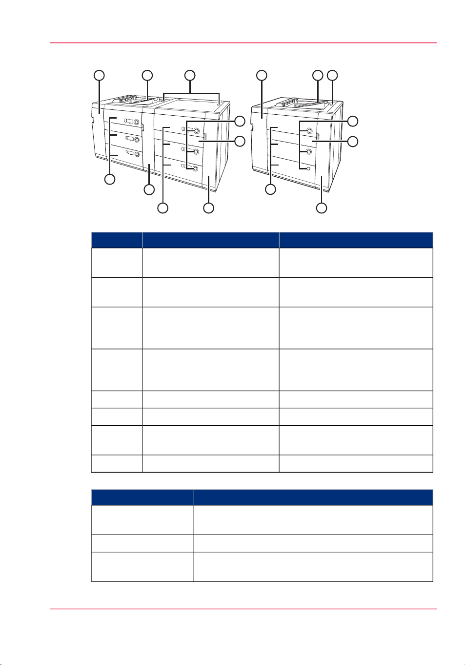
1 2 3
4
5
6
7
8
7
1 2 3
4
5
6
7
Parts of the paper module#
Front Cover (Buffer Pass)1
The paper modules
FunctionComponent
Open this cover to remove jammed
paper
#
3
Description
ity
Escape tray2
Main power switch
(POD Deck-A1 and
Secondary POD-Deck-A1)
Open button4
Paper trays7
ValueSpecification
Optional 3-tray paper module; up to 2 paper modules can
be installed
2 x 1000 sheets, 1 x 2000 sheets (80 g/m² / 22 lb. Bond)Paper trays
8000 sheets (2 paper modules)Maximum paper capac-
Receives detected double sheets to
avoid paper jams
Press to the "I" side to turn ON the
paper module
Press to open the paper tray when
you need to load paper or check for
a paper jam
Gives access to jammed paperHorizontal pass cover5
Gives access to jammed paperFront right cover6
Contains the media that will be
printed
Gives access to jammed paperTandem pass cover8
Chapter 2 - Main parts 27
Page 28

The paper modules
Dimensions (WxDxH)
ValueSpecification
Left-hand paper module: 982 x 792 x 1095 mm / 38.66"
x 31.18" x 43.11"
Right-hand paper module: 811 x 792 x 1095 mm / 32" x
31.18" x 43.11"
Weight
Power requirement
Power consumption
Paper feed technology
250 kg / 551 lbs
480 kg / 1058 lb for tandem of first and second paper
module
EUR:
POD Deck-A1: 220-240 V AC, 50/60 Hz, 6 A
Secondary POD Deck-A1: From POD Deck-A1 (200-240
V AC, 50/60 Hz, 2.8 A)
US:
POD Deck-A1: 200-208 V AC, 50/60 Hz, 6 A
Secondary POD Deck-A1: From POD Deck-A1 (200-240
V AC, 50/60 Hz, 2.8 A)
EUR:
POD Deck-A1 only: 850 W maximum
POD Deck-A1 + Secondary POD Deck-A1: 1500 W
maximum
US:
POD Deck-A1 only: 750 W maximum
POD Deck-A1 + Secondary POD Deck-A1: 1380 W
maximum
•
Suction feed
•
Air separation
Features
Bulk paper module
Optionally, you can extend the printer with a bulk paper module with a capacity of 3,500
sheets.
Chapter 2 - Main parts28
•
Paper level detection (visual)
•
Automatic tray opening
•
Escape tray
For automatic shoot out of sheets in case of double-sheet
feeding
Page 29
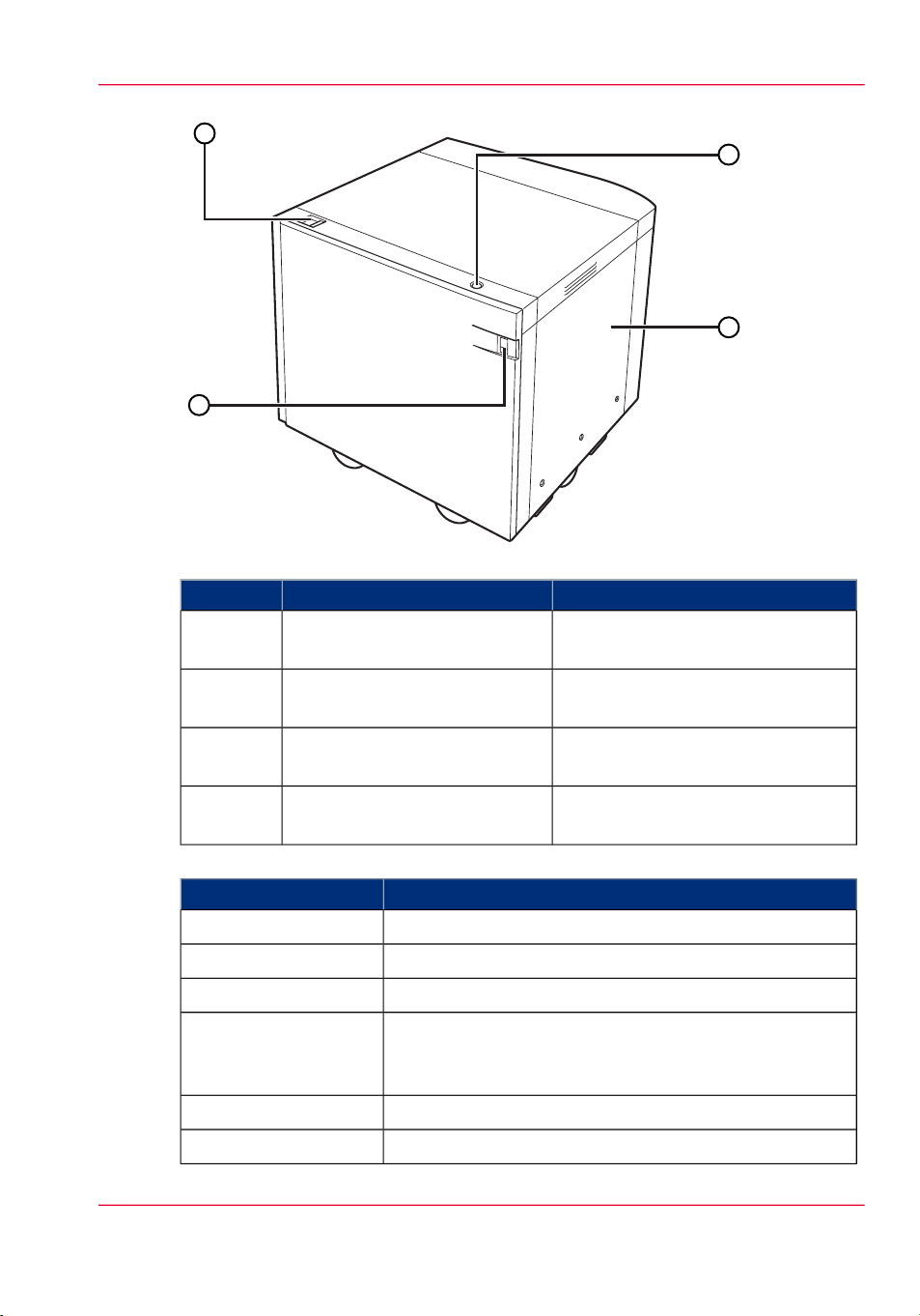
1
2
3
4
Parts of the bulk paper module#
Release button1
The paper modules
FunctionComponent
Detaches the bulk paper module
from the main unit when pressed.
Open button2
Opens the paper tray to load media
or check for a paper jam.
Paper tray3
Contains the media that will be
printed
Paper supply indicator4
Enables you to check the amount of
paper remaining in the paper tray.
#
ValueSpecification
Optional single-tray paper moduleDescription
1 x 3500 sheets (80 g/m² / 22 lb. Bond)Paper trays
64 - 300 g/m² / 17 lb. Bond - 110 lb. CoverPaper weight
Paper size
A4, A4R, A3, SRA3, B5, B4, LTR, LTRR, LGL, Ledger,
12" x 18" / 304.8 x 457.2 mm, 13" x 19" / 330.2 x 482.6
No custom sizes supported
601 x 621 x 570 mm / 23.66" x 24.45" x 22.44"Dimensions (WxDxH)
51 kg / 112 lbsWeight
Chapter 2 - Main parts 29
Page 30

The paper modules
Paper feed technology
Total capacity
Total capacity including the external paper modules#
Total capacity including the bulk paper module#
ValueSpecification
From main enginePower consumption
•
Friction feed
•
Air separation
•
Automatic tray openingFeatures
Total number of sheetsPaper modules
2,000 sheetsInternal paper trays only
6,000 sheetsWith 1 external paper module
10,000 sheetsWith 2 external paper modules
Total number of sheetsPaper modules
2,000 sheetsInternal paper trays only
•Overview of the machine configuration, on page 18
5,500 sheetsWith 1 external bulk paper module
Chapter 2 - Main parts30
Page 31

The tab feeder (optional)
34
1
2
Introduction
The tab feeder is needed to feed tabs via a paper tray.
Tab feeder
The tab feeder (optional)
Parts of the tab feeder#
FunctionComponent
Paper holder1
The paper holder constrains the tab
paper downwards.
Handle2
Grip this handle to install the tab
feeding attachment in the paper trays.
Location fix frame3
Embed the location fix frame in the
hole of the lifter to fix the tab feeding
attachment to the paper deck.
Paper size change screw4
Specifications of the tab feeder#
ValueItem
Description
Needed for reliable tab feeding. One kit is needed per paper
Use this screw to change the tab paper size to A4 or LTR.
tray to support tab feeding
Option for
The paper modules of the main unit and the optional POD
Deck-A1/Secondary POD Deck-A1
Chapter 2 - Main parts 31
Page 32

The tab feeder (optional)
•Overview of the machine configuration, on page 18
•Load tabs via the tab feeder (optional), on page 272
Chapter 2 - Main parts32
Page 33

The special feeder (optional)
1
2
Introduction
You can use the special feeder to feed media to print on manually.
The special feeder (optional)
The special feeder (optional)
Parts of the special feeder#
Slide guides1
Auxiliary tray2
#
ity
Paper size
FunctionComponent
Enables you to match the size of the
paper.
Enables you to guide paper with large
sizes.
ValueSpecification
100 sheets (80 g/m² / 22 lb. Bond)Maximum paper capac-
64 - 256 g/m² / 17 lb. Bond - 95 lb. CoverPaper weight
A3R, A4R, A4, B4R, B5R, B5, A5R, SRA3, 11×17, LGLS,
LTRL, LTRS, STMTS, 12×18, 13×19, Exec
Custom sizes: 139.7 x 182 mm - 330.2 x 487.7 mm / 5.5"
x 7.17" - 13" x 19.2"
Chapter 2 - Main parts 33
Page 34

The special feeder (optional)
NOTE
•
Feed coated paper one sheet at a time. Loading several sheets together may cause
paper jams.
•
Not available in combination with external paper module.
ValueSpecification
Chapter 2 - Main parts34
Page 35

1
2 3
6 5 4
(7)
The automatic document feeder - ADF (optional)
The automatic document feeder - ADF (optional)
Introduction
This section describes the part of the Automatic Document Feeder (ADF).
The automatic document feeder (ADF)
#
FunctionComponent
Open this cover to clear a paper jam.Feeder cover1
Original set indicator2
Original supply tray3
Lights when originals are placed in
the original supply tray.
Place originals face up here for automatic document feeding.
Original output tray4
Receives scanned originals in the order that they are fed.
Chapter 2 - Main parts 35
Page 36

The automatic document feeder - ADF (optional)
SADF tray5
FunctionComponent
Single Automatic Document Feeder
Tray. To feed heavy or lightweight
originals one by one, face down.
Slide guides6
Adjust the slide guides to match the
width of the original.
Helps to close the ADF.ADF Access Handle7
Chapter 2 - Main parts36
Page 37

The color scanner (optional)
1
Introduction
You can use the color scanner to scan bound originals (such as books and magazines),
heavy or lightweight originals, and transparencies. If the color scanner is attached, the
optional ADF or Platen Cover Type K is required.
#
IMPORTANT
When you use the glass plate to copy or scan thick originals, such as books or magazines, do not press down hard on the feeder or glass plate cover.
Color scanner (optional)
The color scanner (optional)
#
FunctionComponent
Glass plate1
Scan bound originals (such as books
and magazines), heavy or lightweight
originals, and transparencies.
Chapter 2 - Main parts 37
Page 38

1
10
2
3
4
5
7
8
9
6
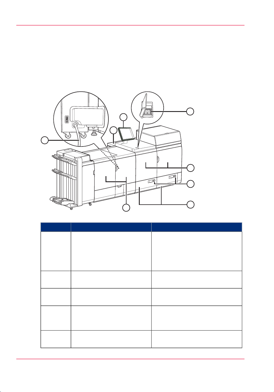
The operator panel
The operator panel
Introduction
The operator panel helps you to carry out print jobs, copy jobs and scan jobs. This section
describes the main components of the operator panel.
#
IMPORTANT
You can clean the screen of the operator panel with a 50% mix of water and isopropyl
alcohol (K2). Use a lint-free cloth. Always put the cleaner onto the cloth and not directly on the screen.
Illustration
[18] The operator panel
The components of the operator panel
The components of the operator panel#
Sleep mode key1
Stop key2
Chapter 2 - Main parts38
FunctionComponent
Depending on whether the printer is currently
active or in the sleep mode:
•
Put the machine into the sleep mode, or
•
Wake up the machine from the sleep
mode.
•
Shut down the printer and controller.
Stop the printer.
•
After a set, or
•
As soon as possible
Page 39

The operator panel
FunctionComponent
Paper tray key3
Get immediate and always access to the 'Trays'
section on the operator panel to do the following, for example:
•
Check the content of all paper trays.
•
Load a new media type into a paper tray.
•
Change the media type which is available
in one of the paper trays.
USB port4
Use the USB port to:
•
Connect the spectrophotometer and calibrate the printer and controller.
•
Print a file from an USB drive
•
Scan to a USB drive
'Schedule' button5
Access the 'Schedule' view to manage the jobs
in the schedule.
'Jobs' button6
Access all functions to print, copy and scan
your documents.
•
Manage or change the settings of jobs in
the lists of 'Waiting jobs', 'Scheduled jobs'
and 'Printed jobs'.
•
Carry out copy jobs and scan jobs.
'Trays' button7
Access the 'Trays' view on the operator panel
to do the following, for example:
•
Check the content of all paper trays.
•
Load a new media type into a paper tray,
or
•
Change the media type which is available
in one of the paper trays.
Chapter 2 - Main parts 39
Page 40

The operator panel
FunctionComponent
'System' button8
Access 'System' view to do the following, for
example:
•
Check the status of the toner, staples and
other supplies.
•
Read the counters.
•
Start maintenance.
•
Set up the preferred workflows.
•
Change a number of default system settings.
•
Adjust the brightness and contrast of the
LCD panel.
•
Shut down the printer.
•
View the content of the Media catalogue
or add temporary media to the Media catalogue.
•
Start maintenance, calibration and media
registration
Dashboard9
The dashboard displays information about the
system status such as:
•
Information about the current printing
process.
•
Information about operator intervention
that is required soon.
•
Information about errors.
•
Information about the status of the toner
reservoir and staple cartridges.
•
Continue the job when the status is 'On
hold'.
Chapter 2 - Main parts40
Page 41

The operator panel
FunctionComponent
Status LED10
Displays the status of the system.
•
Red
The machine has stopped, for example
because a required media type is not available or an error has occurred. Operator
attention is required now.
•
Orange
The machine will stop soon, for example
because more paper is required. Operator
attention is required soon.
The orange light illuminates when the
machine reaches the warning time. The
warning time is a time you can set to determine when the orange light must illuminate. You can set the warning time in the
'System' view of the operator panel.
•
Green
The machine is busy printing. The machine can print longer than the set warning
time. Operator attention is not required.
•Stop the printer, on page 127
•Introduction to the Schedule view, on page 134
•Overview of the machine configuration, on page 18
•The operator attention light, on page 42
•
No color.
The machine is idle. There are no jobs
scheduled for printing.
Chapter 2 - Main parts 41
Page 42

The operator attention light
The operator attention light
Introduction
The operator attention light on top of the printer helps you to monitor the status of the
printer from a distance. The colors of the lights match the printer status that the dashboard
displays.
Illustration
[19] The operator attention light
Status colors
The status colors of the operator attention light#
Red
Chapter 2 - Main parts42
DescriptionColor
The machine has stopped, for example because a required
media type is not available or an error has occurred.
Operator attention is required now.
Page 43

Orange
The operator attention light
DescriptionColor
The machine will stop soon, for example because more
paper is required.
Operator attention is required soon.
The orange light illuminates when the machine reaches the
warning time. The warning time is a time you can set to
determine when the orange light must illuminate. You can
set the warning time in the 'System' section of the operator
panel.
By factory default, the warning time is set to 10 minutes.
So 10 minutes before operator attention is required, the
orange light will illuminate.
Green
The machine is busy printing. The machine can print
longer than the set warning time.
Operator attention is not required.
All lights off
The machine is idle. There are no jobs scheduled for
printing.
•Overview of the machine configuration, on page 18
Chapter 2 - Main parts 43
Page 44

Finishing options
Finishing options
The following optional finishing options are described in separate manuals.
•
High Capacity Stacker-C1
•
Booklet Trimmer-D1
•
Two-Knife Booklet Trimmer-A1
•
Perfect Binder-B1
The Finisher-AJ1/Saddle Finisher-AJ2/Puncher Unit-BC1/BD1/Document Insertion
Unit-C1 is described in this manual.
Chapter 2 - Main parts44
Page 45

(I side)
( side)
1
2
3
2
3
4
5
6 6
7
7
8
The stacker/stapler, optional inserter and optional integrated punch unit
The stacker/stapler, optional inserter and optional integrated
punch unit
Introduction
With the Finisher-AJ1 and Saddle Finisher-AJ2 you can stack and staple prints. With
the Saddle Finisher-AJ2 you can also saddle stitch booklets. With the optional Puncher
Unit-BC1/BD1/BB1 you can punch holes in your prints.
#
IMPORTANT
You cannot attach the optional Finisher-AJ1 and Saddle Finisher-AJ2 to the machine
at the same time.
External view
[20] The Saddle Finisher-AJ2 with inserter (left side) and Finisher-AJ1 (right side)
Main parts#
Main power switch1
Top cover2
FunctionComponent
Press to the "I" side to turn on the
stacker/stapler.
Open the top cover to clear a paper
jam inside the unit.
Chapter 2 - Main parts 45
Page 46

The stacker/stapler, optional inserter and optional integrated punch unit
FunctionComponent
Front cover3
Open the front cover to replace the
staple cartridge, remove jammed paper, or clear a staple jam in the stapler
unit and saddle stitcher unit.
4
Receives saddle stitched booklets.Booklet tray
Saddle Finisher-AJ2 only
5
Auxiliary booklet tray
Saddle Finisher-AJ2 only
Pull out the auxiliary booklet tray to
receive large size booklets.
Receives finished documents.Lower tray6
Receives finished documentsUpper tray7
Inserter8
The inserter is used to feed cover
sheets for printed documents and
booklets. The inserter is also an option for the Finisher-AJ1.
Chapter 2 - Main parts46
Page 47

Internal view
12
The stacker/stapler, optional inserter and optional integrated punch unit
[21] The finisher module
Main parts#
Punch waste tray1
Staple waste tray2
FunctionComponent
Pull out the punch waste tray to remove punch waste.
Pull out the staple waste tray to discard the staple waste.
Chapter 2 - Main parts 47
Page 48

The stacker/stapler, optional inserter and optional integrated punch unit
Finishing options
#
IMPORTANT
•
Do not place anything other than output paper in the trays of the finisher, as doing
so may damage the trays.
•
Do not place anything under the trays of the finisher, as doing so may damage
the trays.
[22]
#
NOTE
•
If the finishing is used, the output trays move downward as the stack of paper that
is output increases in quantity and thickness. Once an output tray has reached its
stacking limit, subsequent prints are automatically delivered to the next available
tray. If all of the available trays have reached their stacking limits, printing stops
temporarily. Remove all of the output paper from the trays. The trays move upward
and printing resumes.
•
If the optional Booklet Trimmer-D1 is attached to the Saddle Finisher-AJ2, you
cannot output stapled paper to the booklet.
#
CAUTION
Do not place your hands in the part of the tray where stapling is performed (near
the rollers) when a finisher is attached, as this may result in personal injury.
Chapter 2 - Main parts48
Page 49

The stacker/stapler, optional inserter and optional integrated punch unit
[23]
Stapling
#
IMPORTANT
•
During stapling, the output trays move downward as the stack of paper that is
output increases in quantity and thickness. Once an output tray has reached its
stacking limit, or after 100 sets of prints have been output, printing and stapling
stop temporarily. Remove all of the stapled prints from the output tray, and
printing and stapling resume.
•
You can corner and double staple A3, B4, A4, A4R, and B5 paper.
•
You can corner and double staple 11" x 17", LGL, LTR, LTRR and EXEC paper.
•
You cannot staple vellums, transparencies, or labels.
•
Do not pull copies or prints out of the output area while they are being stapled.
Remove the copies or prints after they are output to one of the output trays.
#
NOTE
•
If you want to staple more than 50 sheets (80 g/m² /22 lb Bond) of A3, B4, or
A4R paper, or 100 sheets (80 g/m² / 22 lb Bond) of A4 or B5 paper, the
copies/prints are only offset but not stapled. In addition, when selecting coated
or heavy paper, you may not be able to use stapling even if the number of sheets,
including sheet insertions or job separators, is below the set limit of a finisher.
•
If you want to staple more than 50 sheets (80 g/m² / 22 lb Bond) of 11"x 17",
LGL or LTRR paper, or 100 sheets (80 g/m² / 22 lb Bond) of LTR or EXEC paper,
the copies/prints are only offset but not stapled. In addition, when selecting coated
or heavy paper, you may not be able to use stapling even if the number of sheets,
including sheet insertions or job separators, is below the set limit of a finisher.
•
If the machine stops while stapling because almost all of the staples have been used
the staple cartridge must be replaced.
•
Saddle stitching (booklets)
Chapter 2 - Main parts 49
Page 50

Cross Section Cross Section
The stacker/stapler, optional inserter and optional integrated punch unit
#
IMPORTANT
•
Saddle stitching (booklets) is available only if the Saddle Finisher-AJ2 is attached.
•
The maximum number of sheets that can be saddle stitched differs depending on
the paper weight and type.
- When using plain paper (80 g/m² / 22 lb Bond), 25 sheets of paper (100 pages)
can be saddle stitched at once.
- When using coated paper (80 g/m² / 22 lb Bond), 15 sheets of paper (60 pages)
can be saddle stitched at once.
•
The paper sizes that can be saddle stitched are: 330.2 mm x 482.6 mm, 320 mm
x 450 mm (SRA3), 304.8 mm x 457.2 mm, A3, B4, A4R, and irregular size (210
mm x 279.4 mm to 330.2 mm x 487.7 mm).
The paper sizes that can be saddle stitched are: 13" x 19", 12.60" x 17.72", 12" x
18", 11" x 17", LGL, LTRR, and irregular size (8 1/4" x 11" to 13" x 19 13/64").
•
The accuracy of folds created with saddle stitching may vary, depending on the
paper type and the number of sheets.
•
Saddle pressing
Saddle press enables you to compress a saddle stitched booklet spine.
[24]
#
IMPORTANT
Saddle press is automatically used when you select booklet.
#
NOTE
To make sure that saddle pressing is effective, you must saddle stitch more than nine
sheets of paper (including one cover sheet).
•
Punching
Chapter 2 - Main parts50
Page 51

80 mm
Puncher Unit-BC1 (2 holes)
80 mm 80 mm 80 mm
Puncher Unit-BC1 (4 holes)
The stacker/stapler, optional inserter and optional integrated punch unit
#
IMPORTANT
•
Punching is available only if the Puncher Unit-BB1/BC1/BD1 or Professional
Puncher-B1 is attached.
•
Only the following paper size can be hole punched:
A3, B4, A4, A4R, B5, or B5R / 11" x 17", LGL, LTR, LTRR, or EXEC
•
When the Puncher Unit-BC1 is attached, only A3 or A4 paper can be punched
in four holes.
•
If only the optional Puncher Unit-BB1 is attached, the machine automatically
selects how many holes to punch depending on the selected paper size.
- Two holes in case of LGL and LTRR
- Three holes in case of 11" x 17", LTR and EXEC
•
Holes cannot be punched in paper heavier than 201 g/m² / 54 lb Bond, vellums,
transparencies, labels, or prepunched paper.
•
Paper that is fed from the optional Document Insertion Unit-C1 cannot be hole
punched.
#
NOTE
The distance between the punch holes is shown in the illustration below
[25]
[26]
Chapter 2 - Main parts 51
Page 52

21 mm 70 mm 21 mm
Puncher Unit-BD1
4 1/4"
(108 mm)
4 1/4"
(108 mm)
2 3/4"
(70 mm)
Three Holes Two Holes
5
4
3
2
1
1
The paper is saddle folded
with a m
aximum of 5 sheets
seipoCslanigirO
The stacker/stapler, optional inserter and optional integrated punch unit
[27]
Chapter 2 - Main parts52
[28] Puncher Unit-BB1
•
Folding
Folding folds multiple sheets in 2-folds.
[29]
Page 53

The stacker/stapler, optional inserter and optional integrated punch unit
#
IMPORTANT
•
Saddle folding is available only if the Saddle Finisher-AJ2 is attached.
•
The paper is saddle folded with a maximum of 5 sheets (80 g/m²), and then output.
•
The sizes of paper that can be used with saddle folding are:
- 330.2 mm x 482.6 mm, 320 mm x 450 mm (SRA3), 304.8 mm x 457.2 mm,
A3, B4, A4R, and irregular size paper (210 mm x 279.4 mm to 330.2 mm x 487.7
mm).
•
- 13" x 19", 12.60" x 17.72", 12" x 18”, 11" x 17", LGL, LTRT and irregular size
paper (8 1/4" x 11" to 13" x 19 13/64").
#
NOTE
The following are paper sizes that can be output to the output trays of the machine.
However, some paper sizes may not be output, depending on the set functions.
Input options#
Booklet trayLower trayUpper trayPaper size
A3
-A4
A4R
--A4R
Custom size
139.7 mm x
182 mm to
)²)¹
330.2 mm x
487.7 mm
)¹ Only the custom size (182 mm x 182 mm to 330.2 mm x 487.7 mm) can be output.
)² Only the custom size (210 mm x 279.4 mm to 330.2 mm x 487.7 mm) can be output.
Input options#
Booklet trayLower trayUpper trayPaper size
11" x 17"
-LGL
Chapter 2 - Main parts 53
Page 54

The stacker/stapler, optional inserter and optional integrated punch unit
LTR
Custom size
139.7 mm x
182 mm to
330.2 mm x
487.7 mm
)¹ Only the custom size (7 1/8" x 7 1/8" to 13" x 19 13/64" (182 mm x 182 mm to 330.2
mm x 487.7 mm)) can be output.
)² Only the custom size (8 1/4" x 11" to 13" x 19 13/64" (210 mm x 279.4 mm to 330.2
mm x 487.7 mm)) can be output.
#
NOTE
The Booklet Tray can only be used when the Saddle Finisher-AJ2 is attached.
Booklet trayLower trayUpper trayPaper size
--LTRR
-EXEC
)²)¹
Optional accessories
[56] Staple-N1: a case that holds staples for stapling
Chapter 2 - Main parts54
Page 55

The stacker/stapler, optional inserter and optional integrated punch unit
[57] Staple-P2: a case that holds staples for saddle stitching
•Removing the punch waste, on page 290
•Replacing the staple cartridge in the stapler unit, on page 306
Chapter 2 - Main parts 55
Page 56

( I side)
( side)
a
b
The puncher
The puncher
Introduction
The Professional Puncher Integration Unit-A1 reverses the paper punched by the Professional Puncher-B1.
#
IMPORTANT
Always keep the main power switch of the Professional Puncher-B1 inside the front
cover turned to the "I" side. In this case, the main power switch of the Professional
Puncher-B1 works with the main power switch of the Professional Puncher Integration
Unit-A1 automatically.
[58] Power switch of Professional Puncher-B1
#
IMPORTANT
Illustration
[59] Professional Puncher Integration Unit-A1
If the main power switch of the Professional Puncher-B1 is turned to the "O" side,
turn it to the "I" side before turning ON the main power switch of the Professional
Puncher Integration Unit-A1.
Chapter 2 - Main parts56
Page 57

The puncher
#
FunctionComponent
Open this cover to clear a paper jam.Front cover1
Main power switch2
Press to the "I" side to turn ON the
Professional Puncher Integration
Unit-A1.
Chapter 2 - Main parts 57
Page 58

The puncher
Chapter 2 - Main parts58
Page 59

Chapter 3 Operating concept
Page 60

Operating concept
Operating concept
Introduction
To maximize efficient and productive printing, the operating concept of the system, is
based on the following principles.
•
Document preparation / job submission and production printing are clearly separated
steps in the workflow.
•
Media definition is done by choosing from a media catalog instead of selecting trays.
•
Operation is intuitive and convenient at all workflow steps.
•
The workflow is entirely integrated because all components work together seamlessly.
Chapter 3 - Operating concept60
Page 61

Illustration
1
2
3
5
6
7
8
4
Operating concept
[60] The components of the complete system
Chapter 3 - Operating concept 61
Page 62

Operating concept
Components overview
#
Settings Editor1
Main taskComponent
Define initial and default system settings
•
Set default print and workflow settings
•
Define default color management settings like
color pre-sets
•
Maintain the media catalog
•
Set scan settings
2
Printer driver
Available via any application, e.g. Adobe Acrobat, Microsoft Word.
3
PRISMAprepare
Optional software
Document preparation and job submission
•
Document preparation for production printing
•
Define settings per print job
•
Send print jobs to the printer
Document preparation and job submission
•
Document preparation with full preview for
production printing
•
Define settings per page for complex print jobs
•
Send print jobs to the printer
•
Send print jobs to the PostScript printers in
the network
4
PRISMAaccess
Optional software
Workflow management for production environments
•
Easy integration in PDF workflow
•
Job submission via web
•
Acceptance and preparation of incoming jobs
•
Link to PRISMAprepare
•
Link to all production printers
•
Link to PRISMAarchive or your local reprint
archive
5
PRISMAsync controller
Process print jobs
•
Rip print jobs
Remote Monitor6
Monitor production printing remotely
•
Monitor remotely when operator intervention
is needed
Chapter 3 - Operating concept62
Page 63

Operating concept
Main taskComponent
Operator panel7
Manage production printing from the 'Schedule'
view
•
Monitor your print and copy jobs
•
Load and assign media to the media trays
Manage jobs from the 'Jobs' view
•
Schedule print and copy jobs
•
Change job properties if required
•
Define and handle copy jobs
•
Define and handle scan jobs
Manage media from the 'Trays' view
•
Change the media that is currently assigned to
a paper tray
•
Assign the media to the paper tray
Manage the system from the 'System' view
•
Calibrate the system
•
Perform maintenance tasks
•
Set default workflow and printer settings
•
View the media catalog, add temporary media
and perform media registration
•
8
imagePRESS
C7010VPS/C6010VPS/C6010S
Production printing
•
Finishing
Chapter 3 - Operating concept 63
Page 64

Access the Settings Editor
Access the Settings Editor
Introduction
The Settings Editor is a web-based application and therefore accessible via an Internet
browser. The Settings Editor enables you to manage settings or to display information in
the following areas.
•
'Media'
•
'color'
•
'Preferences'
•
'Workflow'
•
'Configuration'
•
'Support'
Before you begin
Make sure you have the following information.
•
The IP address or hostname of the controller.
•
The key operator password to change all settings except for the settings in the 'Configuration' tab.
•
The administrator password to change all settings including the settings in the 'Configuration' tab.
Access the Settings Editor
Open the Internet browser.
1.
At the address bar, enter the IP address or host name of the controller.
2.
Chapter 3 - Operating concept64
Page 65

The Settings Editor appears.
Access the Settings Editor
Result
You can now use the Settings Editor to make changes in the above listed areas.
Chapter 3 - Operating concept 65
Page 66

Maintain the 'Media catalog'
Maintain the 'Media catalog'
Introduction
The 'Media catalog' is a list of media with pre-defined characteristics including the 'Media
family'.
See ‘Maintain the 'Media families' ’ on page 68.
Before you begin
Make sure you have the following information.
•
Key operator or system administrator password
Maintain the 'Media catalog'
From the navigation bar, select the 'Media' tab.
1.
From the 'Media' tab, select 'Media'.
2.
The 'Media catalog' window appears.
[62] The 'Media catalog' window
From the toolbar, select the required option to maintain the 'Media catalog'.
3.
Chapter 3 - Operating concept66
Page 67

Maintain the 'Media catalog'
#
NOTE
When you add, change or import new media, make sure that you enter the correct
values for the following options.
•
'Weight'
•
'Media family'
•
'Media type'
The correct values are required for optimal print quality.
[63] The 'Add new media' window
Chapter 3 - Operating concept 67
Page 68

Maintain the 'Media families'
Maintain the 'Media families'
Introduction
The 'Media family' is a group of media that uses the same output profile. The controller
provides by default the media families coated and uncoated. An expert can create a new
media family for a specific group of media. A media family refers to 1 of the following
halftones.
•
'Normal'
•
'Fine'
•
'Error diffusion'
Before you begin
Make sure you have the following information.
•
Key operator password
Maintain the 'Media families'
From the navigation bar, select the 'Media' tab.
1.
From the 'Media' tab, select 'Media family'.
2.
The 'Media families' window appears.
[64] The 'Media families' window
Chapter 3 - Operating concept68
Page 69

Maintain the 'Media families'
From the toolbar, select the required option to maintain the 'Media families'.
3.
[65] The 'Add media family' window
Chapter 3 - Operating concept 69
Page 70

Maintain the 'Color pre-sets'
Maintain the 'Color pre-sets'
Introduction
A color pre-set is a collection of color and quality settings that matches a specific document
type, workflow or color application. The color pre-sets enable users to select the correct
settings easily without in-depth knowledge about color management.
The controller provides the following color pre-sets to start printing immediately.
•
'Office documents' to print the Microsoft Office documents.
The Microsoft Office documents use the RGB color space.
•
'Photographic content' to print documents from photo editing or layout applications.
These documents use the CMYK color space.
A color expert can create more color pre-sets. The color pre-sets appear in the printer
driver and in PRISMAprepare (optional software).
Maintain the 'Color pre-sets'
From the navigation bar, select the 'color' tab.
1.
From the 'color' tab, select 'Color pre-sets'.
2.
The 'Color pre-sets' window appears.
[66] The 'Color pre-sets' window
Chapter 3 - Operating concept70
Page 71

Maintain the 'Color pre-sets'
From the toolbar, select the required option to maintain the 'Color pre-sets'.
3.
[67] The 'Add color pre-set' window
Chapter 3 - Operating concept 71
Page 72

Maintain the 'Input profiles'
Maintain the 'Input profiles'
Introduction
An input profile defines a reference color workspace for the color data of the objects in
the document. An input profile is used to define colors in a device independent way.
Maintain the 'Input profiles'
From the navigation bar, select the 'color' tab.
1.
From the 'color' tab, select 'Input profiles'.
2.
The 'Input profiles' window appears.
[68] The 'Input profiles' window
From the toolbar, select the required option to maintain the input profiles.
3.
Chapter 3 - Operating concept72
Page 73

Maintain the 'Output profiles'
Introduction
An output profile defines a reference color workspace for the color data of the objects in
the document. An output profile is used to define colors in a device independent way.
Maintain the 'Output profiles'
From the navigation bar, select the 'color' tab.
1.
From the 'color' tab, select 'Output profiles'.
2.
The 'Output profiles' window appears.
Maintain the 'Output profiles'
[69] The 'Output profiles' window
From the toolbar, select the required option to maintain the output profiles.
3.
Chapter 3 - Operating concept 73
Page 74

Maintain the 'Spot colors'
Maintain the 'Spot colors'
Introduction
Spot colors are used to standardize colors to make sure that colors match regardless of
the equipment used to produce the color.
Maintain the 'Spot colors'
From the navigation bar, select the 'color' tab.
1.
From the 'color' tab, select 'Spot colors'.
2.
The 'Spot colors' window appears.
[70] The 'Spot colors' window
From the toolbar, select the required option to maintain the spot colors.
3.
Chapter 3 - Operating concept74
Page 75

Prepare print jobs with PRISMAprepare
Prepare print jobs with PRISMAprepare
Introduction
Océ PRISMAprepare allows you to prepare the print job completely on page level. You
can preview the result per page. PRISMAprepare is an optional application.
This procedure describes the most important settings for daily use.
Prepare print jobs with PRISMAprepare
Prepare the document.
1.
[71] Lay out preparation with PRISMAprepare
Use the media catalog to define the media.
2.
Chapter 3 - Operating concept 75
Page 76

Prepare print jobs with PRISMAprepare
With PRISMAprepare you can export the media catalogue to PRISMAsync controllers
of the black & white and color systems.
[72] The media catalog in PRISMAprepare
Select the required color pre-set or define customized color settings for optimal print
3.
quality.
•
Select 'Office documents' to print the Microsoft Office documents. The Microsoft
Office documents use the RGB color space.
•
Select 'Photographic content' to print documents from photo editing or layout applications. These documents use the CMYK color space.
Define the required finishing options.
4.
#
NOTE
Please refer to the online help of PRISMAprepare for detailed information.
Chapter 3 - Operating concept76
Page 77

Prepare print jobs with the printer driver
Prepare print jobs with the printer driver
Introduction
The printer driver enables you to prepare the print job completely. The printer driver
appears in all applications running in the Microsoft Windows or Apple Mac OS operating
systems.
This procedure describes the most important settings for daily use.
Prepare print jobs with the printer driver
Use the media catalog to select the media to print on.
1.
[73] The media catalog in the printer driver
Select the required color pre-set or define customized color settings for optimal print
2.
quality.
•
Select 'Office documents' to print Microsoft Office documents. Microsoft Office
documents use the RGB color space.
Chapter 3 - Operating concept 77
Page 78

Prepare print jobs with the printer driver
•
Select 'Photographic content' to print documents from photo editing or layout applications. These documents use the CMYK or RGB color space.
[74] The color pre-sets in the printer driver
Chapter 3 - Operating concept78
Page 79

Define the required finishing options.
3.
Prepare print jobs with the printer driver
[75] The finishing options in the printer driver
#
NOTE
Click the white question mark to open the online help of the printer driver for detailed
information.
Chapter 3 - Operating concept 79
Page 80

Manage production printing
Manage production printing
Introduction
The operating panel of the printer enables you to manage production printing. You
manage all print jobs from the 'Schedule' tab. The Remote Monitor enables you to
monitor the system status from a distance via an internet browser.
Manage production printing
Press the 'Schedule' button at the lower left of the operator panel to access the 'Schedule'
1.
view.
[76] The 'Schedule' view
Monitor operator intervention remotely
Open the Internet Browser.
1.
At the address bar, enter 'http://printername/remoteinfo'.
2.
Chapter 3 - Operating concept80
Page 81

The Remote Monitor displays a fixed time line of 30 minutes.
[77] The remote monitor
Manage production printing
Chapter 3 - Operating concept 81
Page 82

Manage production printing
Chapter 3 - Operating concept82
Page 83

Chapter 4 Operator panel views
Page 84

32
1
4
32
1
4
The dashboard
The dashboard
Introduction
The dashboard is the upper part of the operator panel. The dashboard is always visible,
irrespective of the current view. The dashboard shows the following.
•
The status of the system.
•
The status of the supplies.
•
The status of the finishers.
•
The current process.
•
Instructions for the operator.
•
The 'Continue' button after you stopped the printer.
Illustration
The following illustration shows the dashboard while the machine is busy. The vertical
status bar is green. No action is required.
[78] The dashboard - No action is required
The following illustration shows the dashboard while the machine is busy. The vertical
status bar is orange. Next to the status bar, the dashboard displays a message that indicates
which action is required soon.
[79] The dashboard - Action is required soon
The parts of the dashboard
The dashboard#
1
FunctionNumber
Display the status of the machine, for example Initializing...,
Printing... or Printing will stop.... Each status message can have
a sub-message with additional information.
Chapter 4 - Operator panel views84
Page 85

The dashboard
FunctionNumber
2
Display the file name of the current job (for document printing)
or current stream (for stream printing). Furthermore, the
progress of the current job is displayed.
For document printing, the counter can display the following
information.
•
Set X of Y
•
Sheet X of Y or Sheet X.
X represents the current status of the print job. Y represents the
total number of sets or sheets of a print job.
When the sorting method for a job is set to By set and a set
contains at least 40 pages, then the dashboard displays the set
count (Set X of Y).
When the sorting method for a job is set to By page, or when
you print stream jobs, then the dashboard only displays a sheet
count.
3
Display the action that you must do now or soon. The colors
of the vertical status bar at the left-hand side match the colors
of the LED on the operator panel and the operator attention
light. When the color is orange or red, a message indicates the
required action.
Orange means that action is required soon. How long before
an upcoming action the operator panel starts to display the
message depends on the defined warning time.
Red means that action is required now.
4
Displays a status action when you must do something now or
soon regarding the following items.
•
Finishers.
•
Staple cartridges.
•
Toner reservoir.
#
NOTE
The operator panel can only display one message at a time. When there are more
messages, the operator panel displays the first required or most important message.
Chapter 4 - Operator panel views 85
Page 86

The 'Schedule' view
The 'Schedule' view
Introduction
The 'Schedule' is your daily planning board for print jobs. The 'Schedule' helps you to
keep the machine running.
This section shows and describes the main parts of the 'Schedule'.
#
NOTE
The descriptions of the colors of the bars and the indication of the required amount
of sheets are only valid for document printing. For streaming jobs , all the bars remain
grey until the paper trays are empty or the output locations are full. Then the machine
stops and the bars become red. Furthermore, the media toolbar does not indicate the
required amount of sheets.
The 'Schedule' view
[80] The 'Schedule' view
Chapter 4 - Operator panel views86
Page 87

•Introduction to the Schedule view, on page 134
The 'Schedule' view
Chapter 4 - Operator panel views 87
Page 88

The 'Jobs' view
The 'Jobs' view
Introduction
The 'Jobs' view enables you to access all functions to print, copy and scan your documents.
From the left side of the 'Jobs' view, you can access the following sections.
•
The 'Queues' section.
The 'Queues' section enables you to manage print jobs in the list of 'Scheduled jobs'
and 'Waiting jobs'.
•
The 'Printed jobs' section
The 'Printed jobs' section enables you to manage print jobs in the list of 'Printed jobs'.
•
The 'Copy/Scan' section.
The 'Copy/Scan' section enables you to manage copy and scan jobs using copy templates and scan profiles.
The 'Jobs' view
The job icons may show one or more of the following status icons.
Chapter 4 - Operator panel views88
Page 89

The 'Jobs' view
#
DescriptionIcon
The printer is downloading the document via the network
(spooling)
The printer converts the document into a printable bitmap
(ripping)
The printer is printing
The job is ready for printing
The printer converts and prints simultaneously (ripping
and printing)
The job contains an operator note
•Description of the print job settings, on page 104
•Introduction to the copy function, on page 174
•Description of the copy job settings, on page 176
•Introduction to the scan function, on page 216
•Description of the scan job settings, on page 218
Indicates a streaming job
Indicates a proof print
The job settings are overruled by the PRISMAsync controller settings
Indicates an RIP error
Chapter 4 - Operator panel views 89
Page 90

The 'Trays' view
The 'Trays' view
Introduction
The 'Trays' view has the following functions.
•
Display the current content and filling level of the paper trays
•
Change the media that is currently assigned to a paper tray
•
Assign media to a paper tray
•
Unassign media from a paper tray.
Illustration
[92] Example of a configuration with 1 paper module
•Description of the Trays view, on page 140
Chapter 4 - Operator panel views90
Page 91

The 'System' view
Introduction
The system view enables you to access all functions to maintain and set up the system.
From the left side of the 'System' view, you can access the following sections.
•
The 'Printer' section.
The 'Printer' section enables you to check the toner levels and the status of the waste
boxes and staples of finishing equipment.
•
The 'Maintenance' section.
The 'Maintenance' section enables you to read the counters and start the maintenance
actions.
•
The 'Setup' section.
The 'Setup' section enables you to set up your personal workflow, the behavior of the
operator panel and the advanced system settings.
•
The 'Media' section.
The 'Media' section enables you to view the content of the 'Media catalog'or add
temporary media to the 'Media catalog'.
•
The 'Color management' section.
The 'Color management' section gives access to the following functions.
The 'System' view
Chapter 4 - Operator panel views 91
Page 92

The 'System' view
The 'System' view
•Introduction to the Maintenance section, on page 342
•Introduction to the Setup section, on page 316
•Introduction to the Media section, on page 145
Chapter 4 - Operator panel views92
Page 93

Chapter 5 Power information
Page 94

The power buttons and power modes
The power buttons and power modes
The power buttons
The printer has the following switches and buttons to control the power supply.
•
Power switch
The power switch is located on top of the fusing unit of the printer. The power switch
connects and disconnects the printer to the main power.
•
Sleep button with LED.
The Sleep button is located at the right-hand side of the operator panel.
The Sleep button on the printer allows you to switch between the Ready mode and
the Sleep mode. This is only possible if the power switch is in the 'I' position and
the start-up phase is completed.
The power modes
The power modes#
Sleep buttonPower mode
el
OffOffOff
DescriptionOperator pan-
The printer is completely off.
The power switch is in the 'O'
position. There is no power
consumption. The printer cannot receive or print jobs.
OnOffReady
The printer is ready to print
jobs.
OffOnLow power
The printer automatically enters
the low-power mode after the
time that was defined in the Settings Editor and no button was
pressed.
The printer wakes up when a job
arrives in the list of Scheduled
jobs or when you touch a button. The printer will start to
warm up.
Chapter 5 - Power information94
Page 95

The power buttons and power modes
Sleep buttonPower mode
el
OffOnSleep mode
DescriptionOperator pan-
The printer automatically goes
from the low-power mode into
the sleep mode after the time
that was defined in the Settings
Editor.
You can also put the printer into
sleep mode manually. Press the
Sleep button to do this. The
printer will enter the sleep mode
as soon as the list of Scheduled
jobs is empty.
The printer will wake up from
the sleep mode when you press
the Sleep button or when the
calendar timer expires. The
printer will also wake up when
a printable job arrives in the list
of Scheduled jobs, provided that
the function Automatic wake-up
in the Settings Editor is enabled.
Chapter 5 - Power information 95
Page 96

On/Off
Turn on the controller
Turn on the controller
Introduction
You are advised to turn on the system in the following order.
1.
The controller
2.
The optional equipment
3.
The printer
Illustration
[94] The location of the on/off button
Turn on the controller
Use one of the following options to turn on the controller.
1.
•
•
The controller needs about 1 minute to start up.
Chapter 5 - Power information96
Press the Sleep button at the right-hand side of the operator panel if the system was
shut down from the operator panel.
Press the on/off button of the controller
Page 97

•Turn off the printer, on page 99
•The operator panel, on page 38
•Turn on the printer, on page 98
Turn on the controller
Chapter 5 - Power information 97
Page 98

Turn on the printer
Turn on the printer
Introduction
You are advised to turn on the system in the following order.
1.
The controller
2.
The optional equipment
3.
The printer
How to turn on the printer
Turn on the optional equipment.
1.
Put the main power switch on top of the main unit in the 'I' position.
2.
If required, wait until the controller is ready.
3.
Press the Sleep button at the right-hand side of the operator panel.
4.
•The main unit, on page 22
Chapter 5 - Power information98
Page 99

Turn off the printer
Introduction
#
IMPORTANT
Leave the power switch of the main unit in the 'I' position.
The power switch will automatically switch to the 'O' position.
How to turn off the printer
Touch 'System' -> 'Setup' -> 'Shut down system'.
1.
Select one of the following options.
2.
•
Select 'Shut down' to shut down the controller and printer.
The shut down can take a maximum of 60 minutes.
•
Select 'Forced shut down' to immediately shut down the controller and printer.
#
IMPORTANT
Using the 'Forced shut down' option frequently will damage the printer. Use the
'Forced shut down' option only to turn the printer off and on immediately.
Turn off the printer
Turn off the optional equipment.
3.
•The main unit, on page 22
Chapter 5 - Power information 99
Page 100

Use the Sleep mode
Use the Sleep mode
Introduction
When you do not need the printer for a while, the printer can go into the sleep mode.
The power consumption in the sleep mode is very low.
The printer can enter the sleep mode in 2 ways:
•
Automatically
•
Manually
The timers and settings for the automatic way can be defined in the Settings Editor.
The procedure below describes the manual way.
How to use the sleep mode
To put the printer into the sleep mode, press the Sleep button at the right-hand side
1.
of the operator panel.
The printer will go into the sleep mode when the list of 'Scheduled jobs' is empty.
To put the printer into the sleep mode sooner, use the 'Stop after job' function.
To wake up the printer from the sleep mode, press the Sleep button again.
2.
The printer will warm up. The warming-up time depends on how long the printer was
in the sleep mode.
Chapter 5 - Power information100
 Loading...