

Canon imagePRESS C7000VP Series Trouble Shooting Information
Trouble Shooting Information for C7000VP series
Page 1
Rev. 2.0
2010/09/17
imagePRESS C7000VP Series
Trouble Shooting Information

Trouble Shooting Information for C7000VP series
Page 2
Rev. 2.0
2010/09/17
Table of Contents
1 Error Code ····································································································································· 5
1.1 E000-0102 ·········································································································································· 5
1.2 E007-0001 ·········································································································································· 6
1.3 E012-1080 ·········································································································································· 7
1.4 E014-0100 ·········································································································································· 7
1.5 E016 Photosensitive drum cleaner motor lock ···································································· 8
1.6 E018 ······················································································································································ 9
1.7 E061-0181 ········································································································································ 11
1.8 E062-0300 ········································································································································ 11
1.9 E065-0201 ········································································································································ 12
1.10 E077-0001 ····································································································································· 13
1.11 E078-0001 ····································································································································· 13
1.12 E202-0001 ····································································································································· 14
1.13 E260-2000, E260-0002, E227-0001 ···················································································· 15
1.14 E260-2004 Power Supply Error (ITB Driver PCB right 13V) ···································· 15
1.15 E512-8011 ····································································································································· 16
1.16 E514-8001 only at first power-on in the morning ························································· 18
1.17 E578 ·················································································································································· 18
1.18 E590-8003 ····································································································································· 19
1.19 E747-051B ····································································································································· 19
1.20 E750-0002 ····································································································································· 20
1.21 E750-2012 ····································································································································· 20
1.22 E804-0001 ····································································································································· 21
1.23 E805-0404 ····································································································································· 23
1.24 E805-0701 ····································································································································· 24
1.25 E822-0903 ····································································································································· 25
1.26 E020 ·················································································································································· 26
1.27 E194 and Color Registration Failure ···················································································· 31
1.28 E842-0211 -> New item ········································································································· 42
1.29 E750-2012 at installation -> New item ·········································································· 43
1.30 E805-Y701 -> Additional contents ···················································································· 45
2 Operational Failure ················································································································· 47
2.1 Message prompting for toner supply ····················································································· 47
2.2 Message ‘Check: Punch waste tray’ ··················································································· 48
2.3 Cannot print in spite of ‘Printing’ indication ···································································· 49
2.4 Unavailable RUI although same IP address has been specified ·································· 49
2.5 Directory server name does not appear as SMB directory under browse ············· 50
2.6 ‘Invalid user data’ displays on browser when connecting to RUI ····························· 51
2.7 When importing paper database via RUI, parameters are not carried over ············ 52
2.8 Full adjustment for auto gradation cannot be completed·············································· 52
2.9 Noise from around developing drive assembly/Cracked developing drive gear ··· 53
2.10 Although Tray A is designated as delivery outlet, paper is delivered to Tray B.58
2.11 The red warning light blinks and print operation is not accepted -> New item58
2.12 Noise occurred at operating the refresh roller -> New item ····································· 59
2.13 The magenta developing assembly is not activated -> New item ··························· 60
2.14 Breakage of the splatter prevention sheet at the end of the developing assembly -> New
item 60

Trouble Shooting Information for C7000VP series
Page 3
Rev. 2.0
2010/09/17
3 Image Quality ····························································································································· 62
3.1 Y Tiger / BK Tiger ························································································································ 62
3.2 Uneven gloss area appears at end of output images: Silicon oil is depleted ········· 64
3.3 Soiled back side due to toner at secondary transfer external roller ························ 66
3.4 Soiled back side cases reported from field ········································································· 66
3.5 Magenta fogging throughout page /E020-02b1 during continuous printing job ···· 67
3.6 Color displacement in main scanning direction ································································· 68
3.7 Uneven density due to toner-coating failure of sleeve ·················································· 69
3.8 Trace of delivery reversing roller (uneven gloss) on 1st side of duplex in continuous printing
70
3.9 Glossy Lines equivalent to A4R or LTRR width ································································ 71
3.10 Dirt of pin hole (ring mark) ······································································································ 72
3.11 Trace of bypass decurler belt (uneven gloss) on 1st side of duplex in continuous printing
73
3.12 Wax mark in tandem feeding mode ······················································································· 74
3.13 White spots appear at 68mm intervals ··············································································· 76
3.14 3.7mm Pitch Banding ················································································································· 77
3.15 Density difference on image between front side and rear side ································ 78
3.16 Boomerang ····································································································································· 78
3.17 Hue variation ································································································································· 79
3.18 Uneven image with approx. 60mm pitch in main scanning direction ······················· 79
3.19 Sleeve ghost (shadow image) ································································································· 80
3.20 Streaks due to uneven gloss on the coated paper (sub scanning) ························· 81
3.21 Starter overflow ··························································································································· 82
3.22 Hue variation - 2 ························································································································· 83
3.23 Soiled back side of image (toner overflow from the secondary transfer cleaner) -> New
item 84
3.24 2mm-pitch banding -> New item ·························································································· 85
3.25 Uneven gloss on image (entire surface) -> New item ·············································· 85
3.26 Uneven gloss on image (unevenness at the center in vertical direction) -> New item
86
3.27 Soiled front side of image (fault in ITB cleaning) -> New item ································ 87
3.28 Color displacement in sub scanning direction -> New item·································· 90
3.29 Distorted toner image due to wax -> New item ························································ 91
3.30 Scratches on images of coated paper -> New item ·············································· 93
4 Jam Code ····································································································································· 94
4.1 010E/0209/020A Jam Code: Spring at cross feeding assembly breaks ················· 94
4.2 012A JAM ········································································································································· 95
4.3 1145 Jam with A4R paper: Timing Belt of Saddle Assembly in Saddle Finisher-AB2 slips off
96
4.4 0114 JAM·········································································································································· 97
4.5 Pick-up failure, multi feed (how to adjust the pick-up air flow) ································· 98
-> New item················································································································································ 98
5 Specification-related issues ····························································································· 104
5.1 Description on fixing roller refresh operation and its execution timing ················· 104
5.2 Specifications for staple capacity of Finisher-AB1/AB2 ············································ 105
5.3 Number of sheets and size specification for saddle stitching ··································· 105
5.4 When uploading DC Controller data with SST, ‘SramDCON’ does not appear on SST
screen ························································································································································· 106
5.5 Description of features of Function Expansion PCB on DC Controller PCB 1-2106

Trouble Shooting Information for C7000VP series
Page 4
Rev. 2.0
2010/09/17
6 Adjustment Items ··················································································································· 107
6.1 Adjustments under [Registering/Editing Custom Paper Types] ······························ 107
6.2 Adjusting the Level of Curl Correction of a Custom Paper Type···························· 118
6.3 Shading correction in the main scanning direction ························································ 119
7 Reference ··································································································································· 120
7.1 Table indicating Fixing Temperature Shift ········································································· 120
7.2 Addition of ‘CP-PRINT’ ·········································································································· 122
8 Operations for Sublog (iPRC7000VP) ········································································· 123
8.1 What is Sublog? ···························································································································· 123
8.2 What is RB-SRAM UNIT? ········································································································· 123
8.3 How to obtain RB-SRAM UNIT ····························································································· 123
8.4 Points to note when collecting Sublog ··············································································· 124
8.5 When RB- SRAM UNIT Is Not Equipped ············································································ 124
8.6 How to Collect Sublog ··············································································································· 124
8.7 Information Required at Log Collection ·············································································· 127
8.8 Points to Note ······························································································································ 127
8.9 Reference Information ··············································································································· 128
Trouble Shooting Information for C7000VP series
Page 5
Rev. 2.0
2010/09/17
UL (Sub station)
KTM00460/ KTZ00003/ CWR00003
EU/O (Sub station)
KTQ00429/ KUF00004
CN (Sub station)
KTT00031/ KUJ00001
1 Error Code
1.1 E000-0102
Description
Since the fixing belt did not separate from the fixing roller during warm-up rotation after
power-on, the error code ‘E000-0102’ was indicated.
- E000-0102 can be displayed when the fixing roller main thermistor detection temperature
does not reach 10 deg. C within 100 sec during warm-up.
Note:
When E000/E001/E002/E003/E004/E013/E717/E719 has been indicated, take the appropriate
remedial action, and turn the main power switch ON; then execute the following service mode:
COPIER > Function > CLEAR > ERR. After this, turn the main power switch OFF/ON to clear
the error code. At this time, be sure to switch on the pick-up/delivery option before the main
power of this machine. Otherwise, this machine will fail to recognize the option.
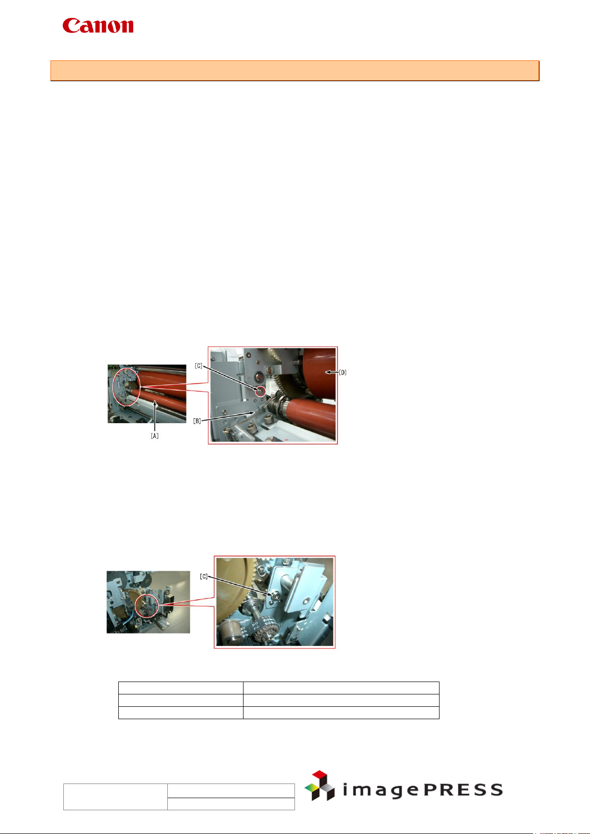
Cause
Since the roller fixing spring [B], which retains the end of the fixing belt [A], contacted to the
screw [C], and thereby was deformed, the fixing belt failed to separate from the fixing roller [D].
This caused the fixing belt to deprive temperature of the fixing roller, as a result the fixing roller
failed to reach the appropriate temperature within the specified period of time, resulting in the
error code.
Field Remedy
1. Check to see if the roller fixed spring [B] (rear) has been deformed; if so, replace it.
2. If the spring has not been deformed, move the fixing belt up and down while pushing it
slightly toward the rear, and then check to see if the roller fixed spring contacts the
screw [C].
3. If the spring contacts the screw, change its type from double sems screw M4x8 to
M4x6.
Reference:
The following are the starting serial numbers having the double sems screw M4x6.
FC6-2048 Roller Fixed Spring
XB2-8400-609 Screw, W/Washer, M4x6
Trouble Shooting Information for C7000VP series
Page 6
Rev. 2.0
2010/09/17
Model
Starting Serial Number
C7000VP (120V)
KTM00348
C6000 (120V)
KTZ00001
C6000VP (120V)
CWR00001
C7000VP (230V EU)
KTQ00397
C6000 (230V EU)
KUF00001
C6000VP (230V EU)
DQF00019
C7000VP (230V CN)
KTT00020
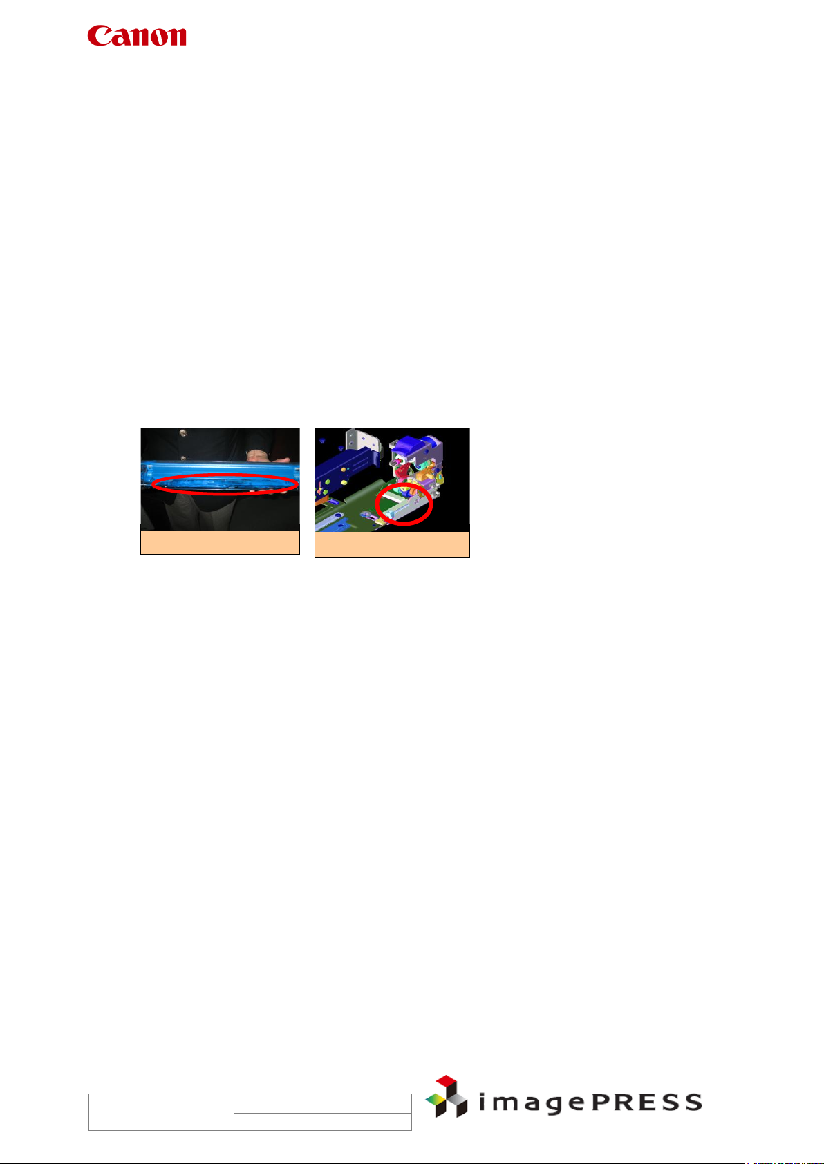
1.2 E007-0001
Description
When the main power switch of this machine was turned on, the error code ‘E007-0001’ was
indicated. This was because the tracking detection arm adjusting plate of the first fixing
assembly was fixed at an improper position, and thus the tracking detection arm that detects
the position of the pressure belt failed to track the edge of the belt.
- E007-0001 can be displayed when the pressure belt of the first fixing assembly has been
displaced completely.
Cause
Since the tracking detection adjusting plate [B] that contacts the pressure belt [A] was disposed
at a slightly higher position, the tracking detection arm [C] contacted the separation roller [D],
and thus failed to track the belt edge. This caused the sensor flag to block off the light from the
primary fixing pressure belt position sensors [E] (PS301 and PS302) simultaneously, causing
the error code.
To deal with this, the accuracy of position adjustment of the tracking detection arm adjustment
plate was improved from the machines having the following serial numbers.
Field Remedy
When the same symptom occurs with a machine having a serial number earlier than the above,
adjust the position of the tracking detection arm adjusting plate in reference to Appendix 1
‘Tracking Detection Arm Adjusting Plate Adjustment Procedure.’
Note:
The screw securing the tracking detection arm adjusting plate is fixed with a (red) bonding
material and generally is not removed. When the adjustment is finished, be sure to fix it with a
bonding material.
Trouble Shooting Information for C7000VP series
Page 7
Rev. 2.0
2010/09/17
FC6-0361-000
Separation Drive Shaft
FC6-0314-000
Belt Tension Roller
FU5-3197-000
20T Pulley
XF2-1305-280
Timing Belt
XG9-0286-000
Ball Bearing
FU6-0343-000
19T Gear
FIRST FIXING ASSEMBLY, LOWER
(Extracts from Parts Catalog FIGURE 816)
Transmission Shaft
Ball Bearing
20T Pulley
Timing Belt
19T Gear
Belt Tension Roller
Transmission Shaft
FC6-0361
1.3 E012-1080
Cause
There are some reported instances from the field where E012-0180 occurred because the
primary transfer roller was omitted to pressurize at the time of installation. This caused
insufficient tension to be applied to the ITB belt and a rotational failure of the belt.
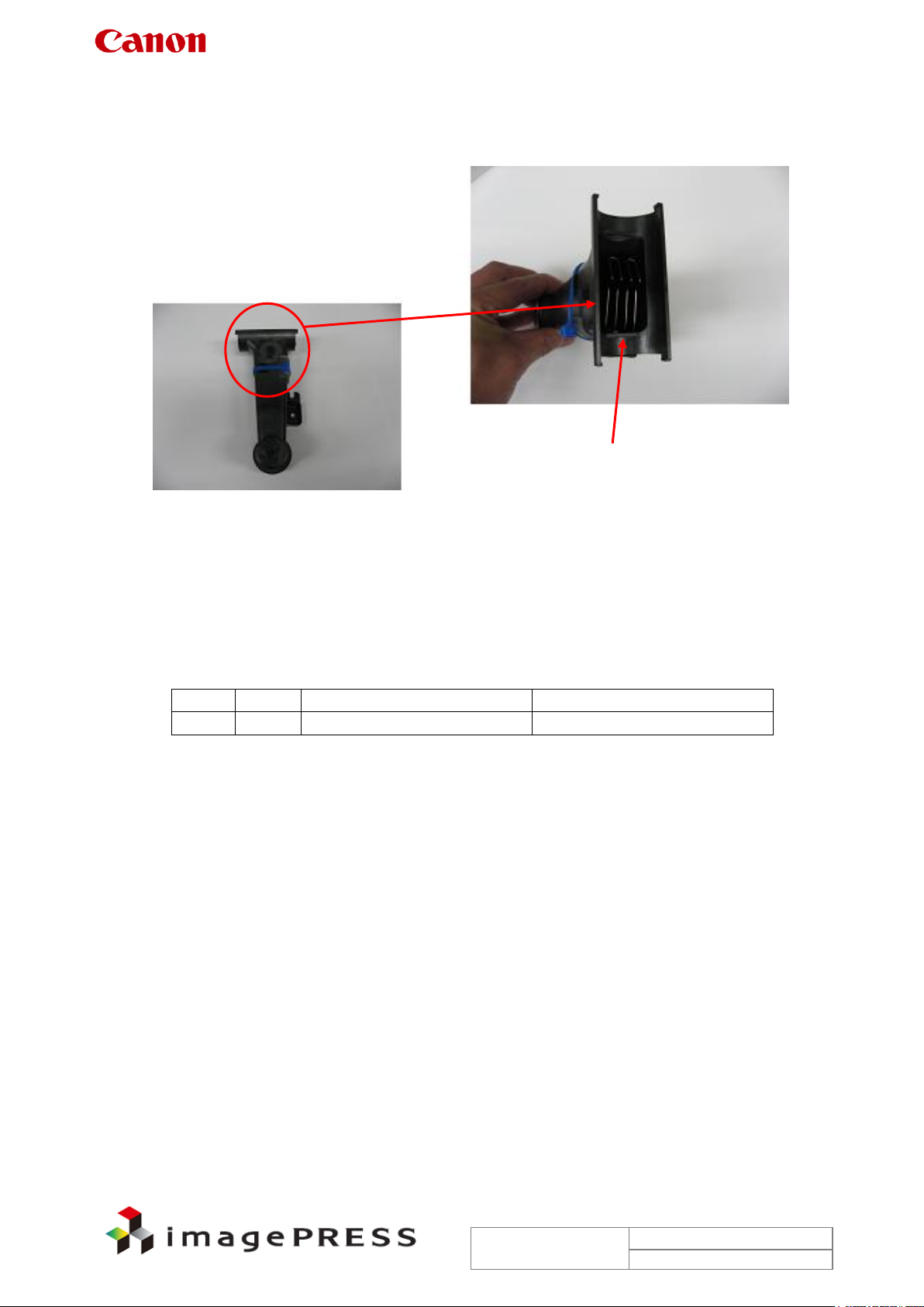
1.4 E014-0100
Description
There are some cases where E014-0100 occurred because the transmission shaft, which is
used in the transmission drive unit in the first fixing assembly lower, was chipped.
- E014-0100 indicates an error of the fixing drive motor (M300) in the first fixing assembly.
Field Remedy
When a similar symptom occurs, inspect the shaft and replace it with a new one if chipping is
confirmed.
Note: Do NOT loosen 2 screws (which fix the transmission drive unit, red circle in the picture)
because the shaft and the gears can be replaced without removing the screws. Be aware of red
marking on them.
Trouble Shooting Information for C7000VP series
Page 8
Rev. 2.0
2010/09/17
No. Part Number
Part Name
1
New
FL3-0541
Waste toner joint assembly
Addition of an agitating spring
1.5 E016 Photosensitive drum cleaner motor lock
Description
There are some cases where the feed screw of photosensitive drum cleaner locks and causes
E016-0x00.
Cause
If outputting high volume of low duty image, waste toner may clog at the waste toner joint
assembly.
Measure for factory
An agitating spring is added to break down the waste toner accumulated at the waste toner joint
assembly. Bringing waste toner feed screw into contact with the agitating spring and moving it
up and down can prevent clog prevented at the joint assembly.
Trouble Shooting Information for C7000VP series
Page 9
Rev. 2.0
2010/09/17
Shutter lever slide area
Developing rail assembly
1.6 E018
< Case 1 > E018-0x11
Description
There are cases where E018-0213 was caused by malfunction of the drum patch shutter or a
soiled patch sensor, or malfunction of the patch detect cleaning motor.
Cause
When continuously printing high-density image (solid image), scattering toner may accumulate
around the drum patch sensor shutter, and may burrow into minute clearance between the
shutter lever slider and the guide. Accordingly, this will make the movement of the shutter lever
dull and fail to detect the patch, resulting in an error of the drum patch sensor shutter drive
motor.
Field Remedy
1. Clean the shutter lever slider and the guide, with lint-free paper moistened with alcohol.
2. Remove the drum patch sensor cleaning motor from the developing rail assembly. Clean
3. Replace the motor with a new one. After installing, turn the main power switch OFF/ON.
4. If the symptom still occurs, replace the developing rail assembly with a new one.
the attachment area of the rail if it is soiled with toner.
FL2-6138 Patch Detect Cleaning Motor
FM2-2109 Developing Rail Assembly
< Case 2 > E018-0x13 keeps displaying after power-OFF/ON to
clear 070A Jam Code or E733-0001
Description
There are some cases where E018 displayed after power-OFF/ON to clear 070A Jam code or
E733-0001.
- 070A can be displayed when the registration paper feeder assembly does not transfer paper
in time for the start of paper-feeding operation. (Related sensor: pre-feed sensor 3 PS141)
- E733-0001 can be displayed when communication with the printer (DC controller PCB 1-1)
is not established at startup.
- E018 can be displayed when a shutter operation error occurs.
Reference:
When turning off the main power switch, be sure to turn off all the optional equipment as well as
the main engine. When turning on, turn on the optional equipment first, and then the main
engine.
Trouble Shooting Information for C7000VP series
Page 10
Rev. 2.0
2010/09/17
Rotate the gear by hand
Field Remedy
In order to deal with this malfunction, the DC controller software has been updated to Ver.12.04.
When the same symptom occurs, check the software version, if it is earlier than Ver.12.04,
upgrade to Ver.12.04 or higher.
As a difference case, the warm gear at the rear side
may get onto the engaging gear. In such a case,
rotate the warm gear in counter clockwise to ease
this state.
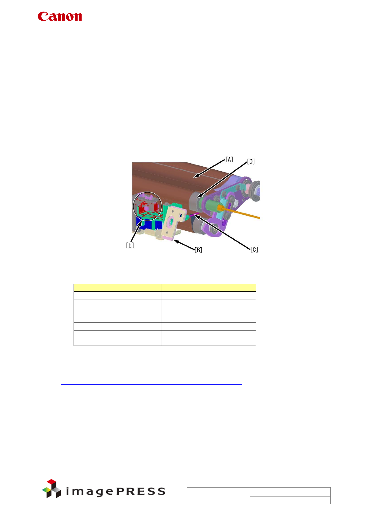
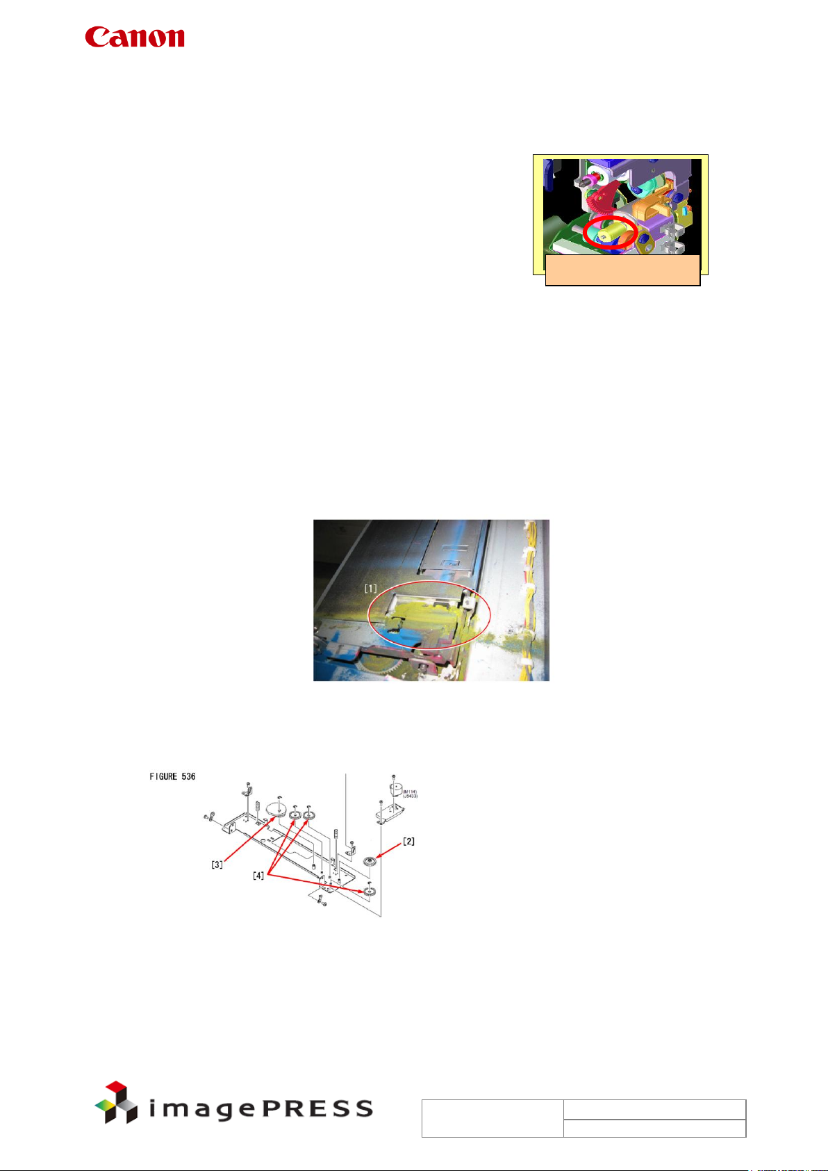
< Case 3 > E018-0102
Description
There are some reported instances from the field where the machine was restored from
E018-0102 after cleaning the edge registration detect assembly. When the same symptom
occurs, go through the following steps in sequence.
- E018-0102 is displayed when the edge registration patch sensor causes shutter-related
error.
Field Remedy
1. If the side scraper (FL2-2025) in the edge registration detect assembly has been soiled like
[1]; clean it, then turn the main power switch OFF/ON.
If the symptom still occurs, clean or replace the 30T/63T gear [2] (FU6-0381), the 60T gear
[3] (FU6-0382) and the 60T gears [4] (FU6-0383, 3 pc) that drive the shutter, then turn the
main power switch OFF/ON.
4. If the symptom still occurs, replace the edge registration detect sensor with a new one.
FU6-0381 30T/63T Gear
FU6-0382 60T Gear
FU6-0383 60T Gear
FM2-2156 Edge Registration Detect Assembly

Trouble Shooting Information for C7000VP series
Page 11
Rev. 2.0
2010/09/17
1.7 E061-0181
Description
There are some reported instances from the field that E061-0181 was solved by replacing the
P-kit drawer assembly (FM2-2079) with a new one, not by replacing the primary corona
assembly. In this field case, service mode COPIER > Display > V00 showed 905V and VFF
showed 802V.
Reference:
The difference in voltage between V00 and VFF normally falls in the range between 400V and
500V.
- E061-0181 is a low laser power error, and can be displayed when the difference in voltage
between VD and VL at the maximum potential control laser power output is 200V or lower.
The meaning of the second digit of detail code is as follows: 1= yellow, 2=magenta, 3= cyan,
and 4= black.
Cause
Since the spring terminal of the H.V. cable to which grid bias is applied was deformed,
unexpected amount of electrical charge was carried, causing the error code.
Field Remedy
Perform the following Steps 1 though 5, which the service manual describes, if the symptom still
recurs, perform Step 6.
1. Clean the dust-proof glass.
2. Re-fit the drum unit.
Note:
Be sure to connect the connectors of the potential sensor and the pre-exposure lamp.
5. In service mode > COPIER > Display > DPOT, check the values of V00-Y (M/C/K)
through VFF-Y (M/C/K). If those values are nearly same, the laser does not go on. In
this case, check the connection of the video cable.
6. Re-fit the primary corona assembly.
7. Replace the following parts.
Potential sensor
Laser scanner unit
Primary corona assembly
8. Check the spring terminal of the H.V. cable of a trouble P-kit for deformation or
disconnection; if there is a problem, replace the drawer connector with a new one.
FM2-2079 P-Kit Drawer Assembly
FM3-4189 Primary Corona Assembly
FM2-9295 Potential Measuring Assembly
FM2-4887 Scanner Assembly
1.8 E062-0300
There are some reported instances from the field where E062-0300 occurred because of a not
securely fitted connector of the Process Unit Driver PCB.
Trouble Shooting Information for C7000VP series
Page 12
Rev. 2.0
2010/09/17
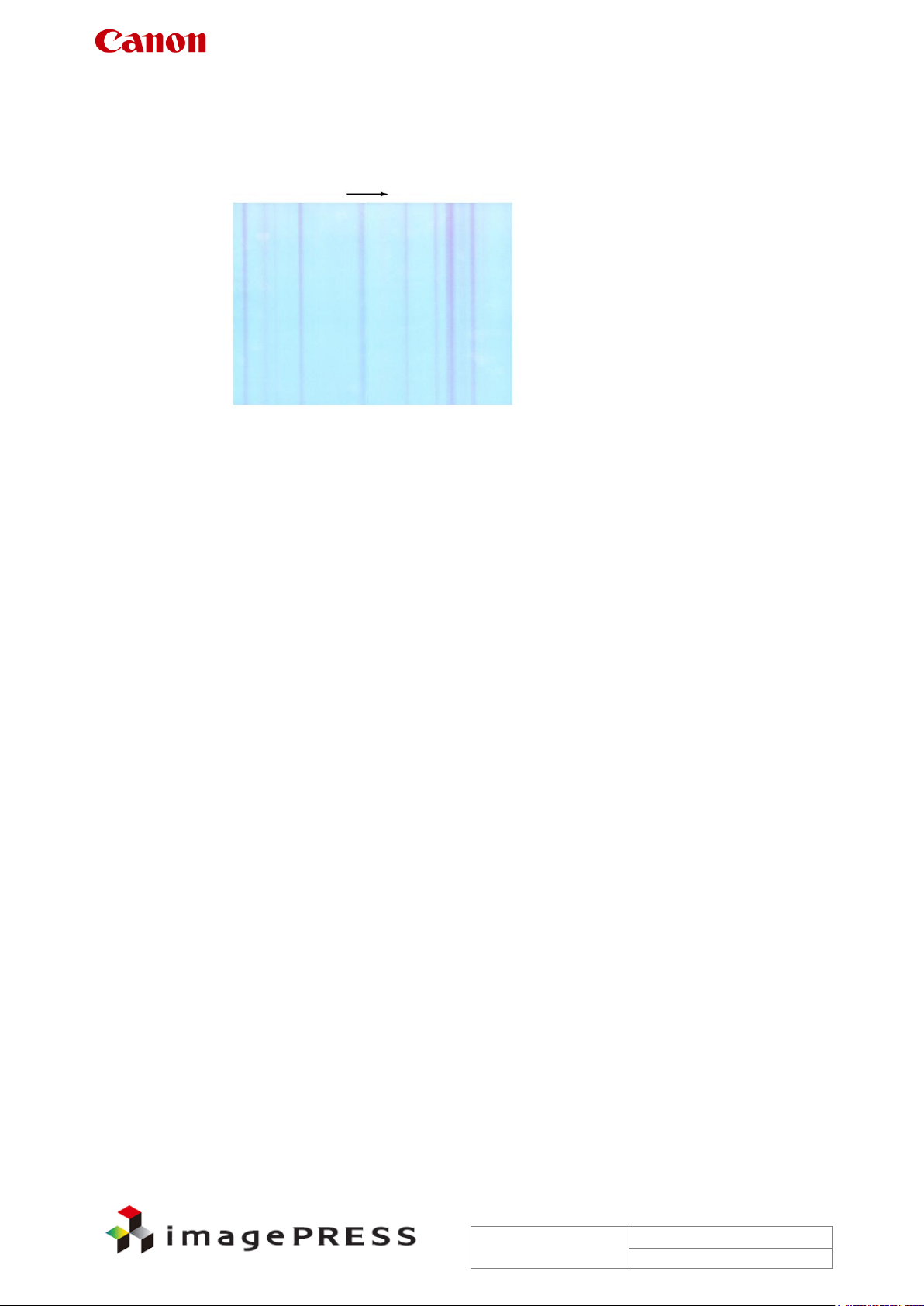
1.9 E065-0201
Description
Since the magenta drum reached the end of life, the primary corona high voltage leakage
occurred at an end portion of the drum, consequently causing either the error code ‘E065-0201’
or blurred band-like image at random in the main scanning direction.
- E065-0x01 can be displayed when the primary corona high voltage leakage has been
detected for 300msec (100msc x 3 times) continuously 200msec after output of the primary
corona high voltage starts. (Y = 1, M = 2, C = 3, and Bk = 4)
Field Remedy
1. In service mode > COPIER > Counter > DRBL-1 > PT-DR-M, check the counter reading; if
it is in the order of 580000 or higher, replace the magenta drum with a new one.
Bk = PT-DRM, Y = PT-DR-Y, C = PT-DR-C
If the symptom still occurs, go through the following steps.
9. Turn the main power switch OFF/ON.
10. Refit all the connectors of the primary corona assembly, and UN137 through UN140
connectors of the HV1 PCB. (Make sure of no uplift connectors.).
11. Replace the primary corona assembly with a new one.
12. Replace the HV1 PCB with a new one.
FM3-4189 Primary Corona Assembly
FM2-7705 Dev. Primary H.V. PCB Assembly

Trouble Shooting Information for C7000VP series
Page 13
Rev. 2.0
2010/09/17
1.10 E077-0001
Description
There are some reported instances from the field where, during initial rotation after clearing a
jam at the main station and closing the front cover, the error code ‘E077-0001’ was displayed.
- E077-0001 displays when engagement/disengagement of the secondary transfer external
roller cannot be completed within 5 sec.
Cause
Since the lever (B-E1) on the Registration Paper feeder assembly (at the main station) is not
securely locked, engagement/disengagement of the secondary transfer external roller cannot
be completed normally.
Field Remedy
1. If the same error code appears when the front cover is closed after work, check to see if the
lever (B-E1) is shifted to the locking position; if not, shift it again. If the lever is in the locking
position, go to Step2.
Note:
If the lever is locked at the wrong position, the lower portion of the cover may not be fitted
completely although the upper portion does so. After the front cover is closed, be sure to
make sure that both upper and lower portions fit completely to the main body.
13. Refit the connector of the secondary transfer pressure release motor (M184).
14. If the symptom still occurs, replace the secondary transfer pressure release motor with
a new one.
FK2-3124 Stepping DC Motor
1.11 E078-0001
Description
There are some reported instances from the field where E078-0001 was displayed because the
ITB cleaner motor did not rotate. When the same symptom occurs, perform the following field
remedy.
- E078-0001 can be displayed when the phase lock signal is not detected for 500msec
(100msec x 5 times) continuously even if 2 sec or more have passed since the start of the ITB
cleaner motor.
Field Remedy
1. Re-fit the connector at J5229S or J5229P on the ITB cleaner motor.
15. Re-fit the connectors at J1340 and J1337 on the I.T.B. Driver PCB Assembly (L).
16. If the symptom still occurs, replace the ITB cleaner motor with a new one.
Reference:
The connector at J1046 on the DC Controller PCB 1-1 is also related to the aforementioned
error code.
FK2-2725 Brushless Motor
FM2-7690 I.T.B. Driver PCB Assembly, L

Trouble Shooting Information for C7000VP series
Page 14
Rev. 2.0
2010/09/17
1.12 E202-0001
Description
There are some reported instances from the field where, upon installation of the cooling fan for
DADF-R1, a harness extending from the fan was pinched and the fuse on the Interface PCB
had an open-circuit, causing the error code E202-0001.
- E202-0001 can be displayed when an error is found during the forward trip of the HP search.
The possible cause of this error is a fault in the scanner HP sensor, the scanner motor or the
reader controller PCB.
Field Remedy
1. When the same symptom occurs, check if the harness of the cooling fan (front/rear) has
been pinched.
2. If the harness has been pinched, suspect removal of harness covering and replace the fan
with a new one. Refer to Appendix 2 ‘Fan installation procedure’.
3. If the symptom still occurs, suspect an open-circuit of fuse on the Interface PCB and
replace the PCB with a new one.
FL2-3427 Front Fan
FL2-3426 Rear Fan
FM2-4662 Interface PCB Assembly
Trouble Shooting Information for C7000VP series
Page 15
Rev. 2.0
2010/09/17
1.13 E260-2000, E260-0002, E227-0001
Description
At the time of installation, there are some cases where multiple error codes such as E260-2000,
E260-0002, or E227-0001 occurred after the operation as follows. For the purpose of toner
supply, the setting of ‘AINR-OFF’ was changed to ‘1’ with the front door open and then the door
switch tool was inserted into the door switch unit. The error code was indicated, so the front
door was closed, however, even the fan did not run.
The following events were confirmed.
a. The fan was running with the front door open.
b. With the front door open, 24V output was confirmed at 24V power supply1 but no output was
at 24V power supply2. However, after opening the front door of the sub station and closing the
main station’s door, 24V output was confirmed.
- E260-2000: 5V, 13V power supply error.
- E260-0002: When activation of 24V-2 cannot be detected even when 1 sec elapsed after the
relay and remote signal was turned on.
- E227-0001: When activation of 24V-1 cannot be detected even when 1 sec elapsed after the
relay and remote signal was turned on.
Cause
The connectors in the 24V power supply 2 were not fitted securely.
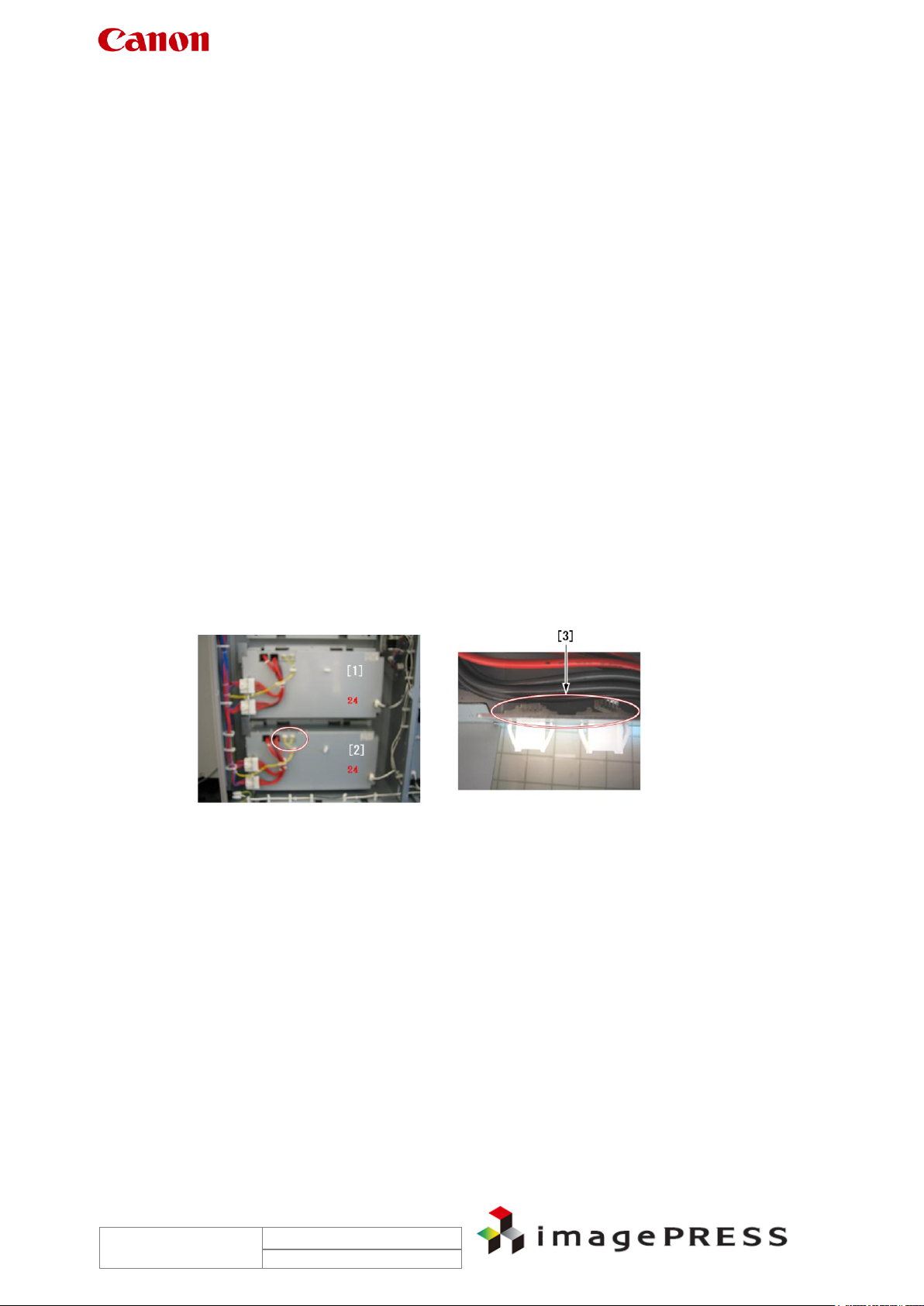
Field Remedy
1. Interchange the 24V power supply 1 [1] and 2 [2], and observe that the error code will be
changed to ‘E260-0001’.
17. If the error code is changed, open the original 24V power supply 2 box and refit the
connectors [3] inside.
18. If the symptom still recurs, replace the 24V power supply 2 with a new one.
FK2-2711 24V DC power supply assembly
1.14 E260-2004 Power Supply Error (ITB Driver PCB right 13V)
Description
There are some reported instances from the field where the error was fixed by cutting the
tie-wrap of the harness between J1032 on the DC-CON and ITB driver PCB (right).
Trouble Shooting Information for C7000VP series
Page 16
Rev. 2.0
2010/09/17
1.15 E512-8011
Description
When the front cover open button was pushed after the stacking operation has been completed,
the stack tray overran the lower limit position, resulting in E512-8011.
- E521-8011: Stack Tray Up/Down Motor Alarm
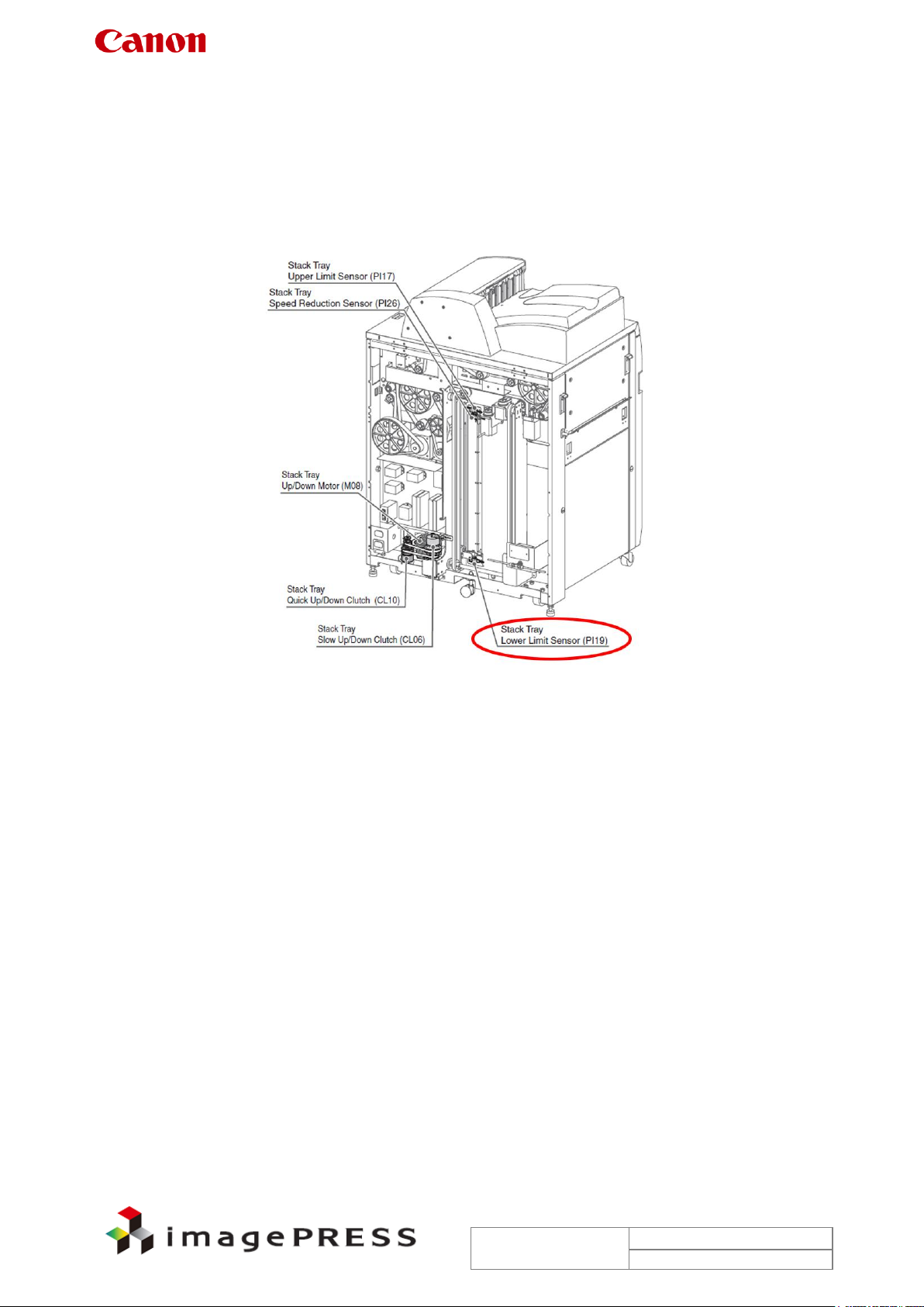
Cause
The stack tray lower limit sensor (PI19) was faulty.
Field Remedy
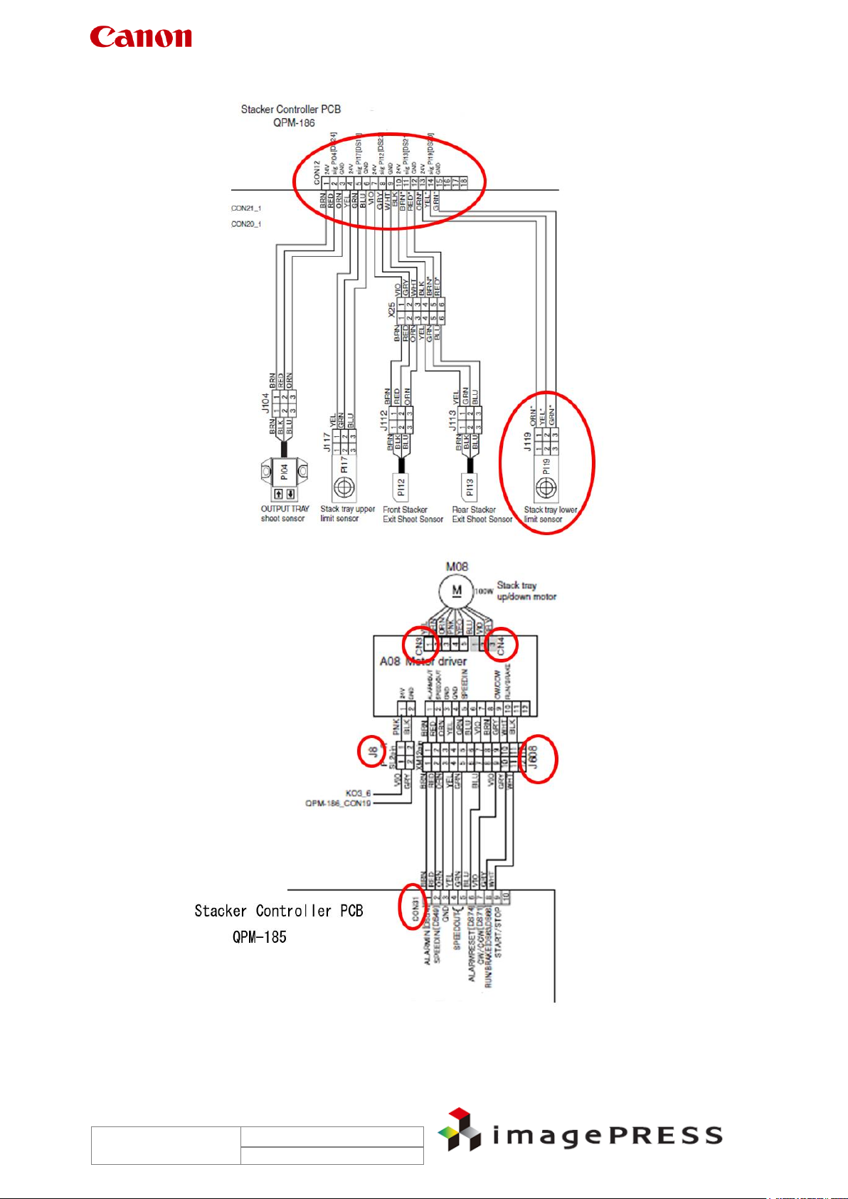
1. Refit the connectors described below:
Connector J119 of the stack tray lower limit sensor (PI19) and CON12 of the stacker
controller PCB (QPM-186)
Stack tray up/down motor (M08) and CN3/CN4 on the motor driver A08.
CON31 of the stacker controller PCB (QPM-186)
J8 and J608 which connect the motor driver A08 and the stacker controller PCB
(QPM-186)
1. Replace the stack tray lower limit sensor (PI19) with a new one
2. When the symptom still recurs, check whether the chain or the warm gear is moving
smoothly. If no problem is found, replace the following parts in order:
Stack tray up/down motor (M08)
Motor Driver A08
Stacker controller PCB (QPM-186)
FC3-1716 SENSOR (PI19)
FC3-4548 MOTOR (M08)
FC3-2666 MOTOR DRIVER (A08)
FC3-3100 P.C.B (QPM186)
Trouble Shooting Information for C7000VP series
Page 17
Rev. 2.0
2010/09/17
Trouble Shooting Information for C7000VP series
Page 18
Rev. 2.0
2010/09/17
Weight of paper
# of sheets applicable (Small size / Large size)
64g to 80g
100sh / 50sh
Over 80g to 81.4g
80sh / 50sh
Over 81.4g to 105g:
60sh / 30sh
Over 105g to 200g:
20sh / 10sh
Over 200g to 300g:
Cover and back cover only
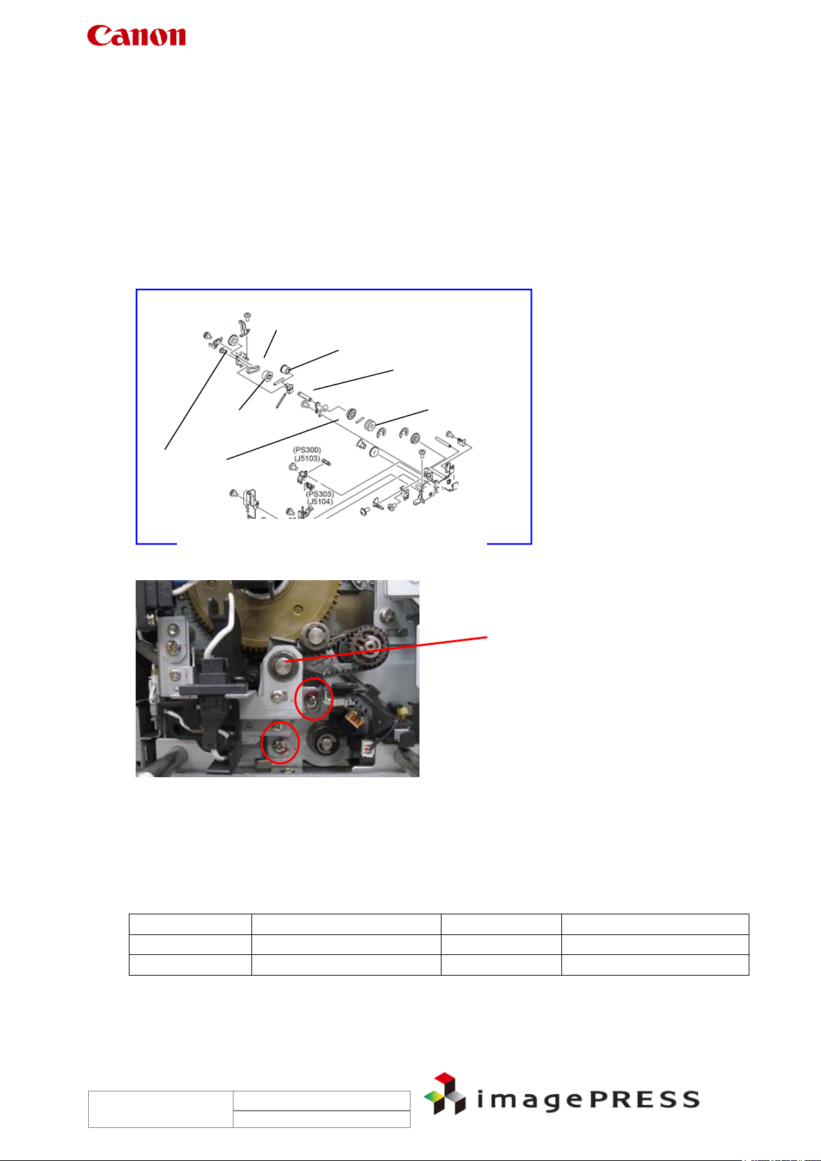
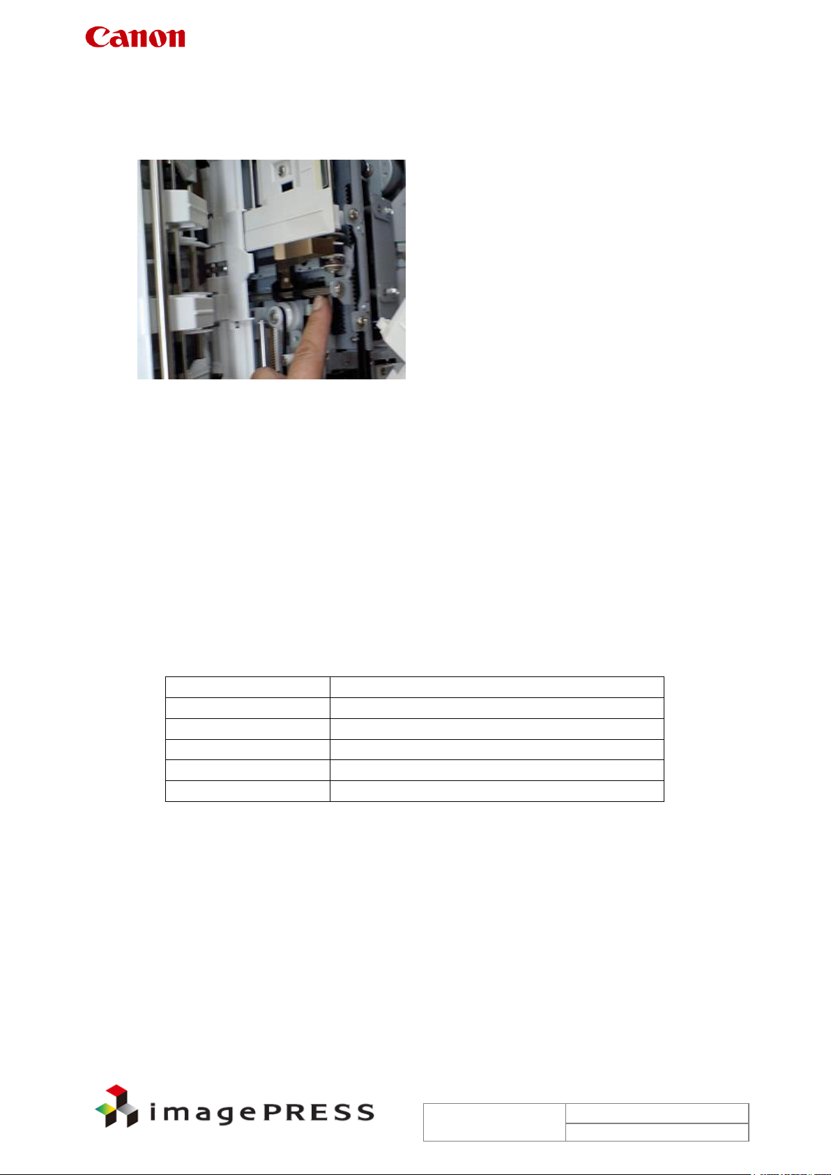
1.16 E514-8001 only at first power-on in the morning
Due to slight weight difference observed when comparing the shifting load of assist plate, the
rail assembly in the photograph below was disassembled and cleaned, and grease was also
reapplied.
1.17 E578
Description
When copying 50 sheets of coated paper of 128g in weight in 2-point staple mode, an error of
paper folding position for saddle stitching occurred and the error code E578 was displayed.
- E578 can be displayed when the feed belt HP sensor does not go ON or OFF within 5 sec
after the feed belt shift motor operation starts. (Knurling error)
Cause
This machine stapled more than the specified number of sheets at a time.
Field Remedy
Before making copies, check paper type and the number of sheets to be stapled at a time.
Reference:
The following describes the specifications for stapling.
Note:
- Thickness of stack has to be less than 11mm for small size, and less than 5.5mm for large
size.
- Length of paper in feeding direction has to be as follows.
For large size: 216.1mm to 482.7mm (e.g. 13x19, 12x18, SRA3, A3, B4, A4R, B5R,
LDR, LGL, LTRR, EXER)
For small size: shorter then 216mm (e.g. A4, B5, A5R, LTR, EXE, STMTR)

Trouble Shooting Information for C7000VP series
Page 19
Rev. 2.0
2010/09/17
1.18 E590-8003
Description
The punch motor brake control varies depending on the type of connected punch unit. If the
dipswitch setting does not match the punch unit connected, the error code ‘E590-8003’
appears.
- E590-8003 can be displayed when a punch motor brake error occurs.
Field Remedy
1. Check the type of connected punch unit.
2. If the connected punch unit is Punch Unit-V1, turn on Bit2 of DIP SW 381 on the optional
switch PCB on the finisher.
Reference:
Regarding other punch units set the appropriate Bit(s) of DIP SW381 as follows:
Punch Unit-U1 (2-hole): turn Bit1 ON
Punch Unit-V1 (2/3-hole): turn Bit2 ON
Punch Unit-W1 (4-hole: FRANCE): turn Bit 1 and 2 ON
Punch Unit-X1 (4-hole: SWEDEN): turn Bit3 ON
1.19 E747-051B
Description
Since the S-B PCB was faulty, the error code ‘E747-051B’ was indicated when copies or
printouts were output after this machine had started up. When the same symptom occurs, go
through the following steps in sequence.
- E747-051B can be displayed when an error occurs in the main controller PCB (MAIN-M).
Field Remedy
1. Turn the main power switch OFF and then ON.
2. If the symptom still occurs, turn the main power switch OFF and clean the terminals of the
following boards, which are piggybacked on the main controller PCB, with lint-free paper
moistened with alcohol; then re-fit the boards.
RO-B PCB
O-B PCB (when an EFI controller is connected) or GU-Short PCB (when an EFI
controller is not connected)
S-B PCB
ZJ-A PCB (piggybacked on the S-B PCB)
LAN-BAR-B PCB
RB-A PCB (w/REOS function, included in the PDL option)
1. If the symptom still occurs, replace the S-B PCB with a new one.
2. If the symptom still occurs, replace the main controller PCB (MAIN-M) with a new one.
3. If the symptom still occurs, replace all the boards listed in Step 2 except the S-B PCB
by new ones.
FM2-7813 Main Controller PCB Assembly, M
FM2-9076 S-B PCB Assembly

Trouble Shooting Information for C7000VP series
Page 20
Rev. 2.0
2010/09/17
1.20 E750-0002
Description
There are some reported instances from the field where, when the machine was relocated the
necessary work was done according to the procedure ‘Relocating the Machine.’ At this time,
however, not the drawer connector mount but each connector was detached from the backside
of the sub station. This caused an error in plugging each connector at the new installation place,
ultimately leading to the error code E750-0002.
- E750-0002 can be displayed when the model name informed by the main controller does
not match with that stored in the DC controller (i.e., same series but different model).
Cause
Communication error occurred between the DC controller software and the main controller
software because the connectors were plugged mistakenly.
Field Remedy
Although it's difficult to identify a connector plugged to the wrong jack from the error code, when
the same error occurs at time of relocation of this machine or service work for the drawer
connector mount, check to see if each connectors are connected to the correct jack.
Note:
When detaching/re-attaching the drawer connector to connect the main station and sub station
during installation or relocation, be sure to work not by the connector but by the drawer
connector mount to prevent errors in plugging connectors.
1.21 E750-2012
Description
There are some reported instances from the field where, at time of replacement of the fixing
intermediate assembly (FM2-9291) the two short connectors for identifying the destination
failed to be reattached, resulting in the error code E750-2012.
- E750-2012 can be displayed when the combination of the DC controller software and the
fixing assembly is not correct.
Field Remedy
When replacing the fixing intermediate assembly, be sure to follow the cautions described in
Appendix 3 ‘Points to Note When Replacing Primary/Secondary Fixing Intermediate Unit.’
Trouble Shooting Information for C7000VP series
Page 21
Rev. 2.0
2010/09/17
J1035
Controller Box Panel
Mount Ass'y
J10
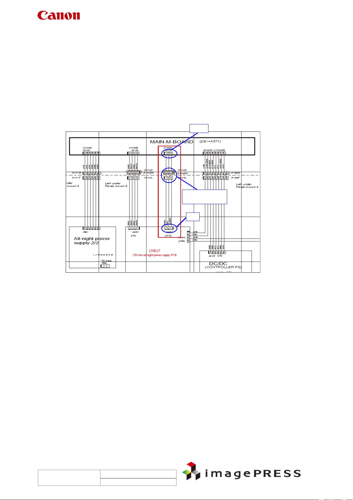
1.22 E804-0001
Description
‘E804-0001’ is an error code that is displayed when a power supply fan error is detected. The
fan related to this code is FM508 mounted in the power unit station.
Cause
The lead wire of the 3-pin connector of FM508 or 3-pin connector ‘J1035’ on the MAIN-M board
contacts the flame plate of the power unit station because of a cause such as wire pinching.
Reference:
The wire is routed from J1035 of the controller BOX via the relay connector to FM508 by
harness connection.
Trouble Shooting Information for C7000VP series
Page 22
Rev. 2.0
2010/09/17
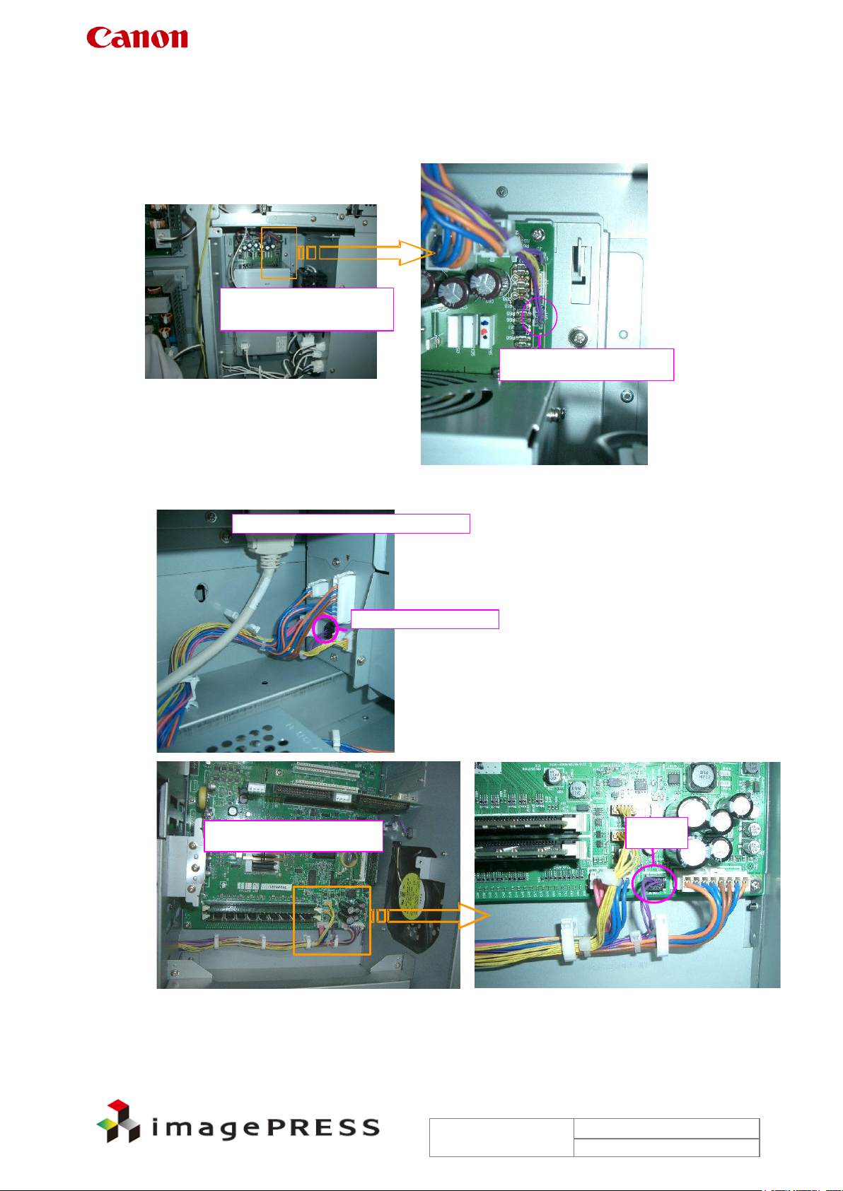
MAIN CONTROLLER BOX Panel Mount
relay area of J10-J1035
J1035
Main controller PCB (M)
DC Power Supply Ass'y,
13V UN507
J10 Upper side is 1P
Field Remedy
1. Check the wire routing with reference to the pictures below.
2. If there is a problem with the wire routing, modify it.
3. If there is no problem with the wire routing, replace the DC power supply assembly (13V
non-all night power supply) or the main controller PCB (M) with a new one.
FK2-2712 DC Power Supply Assembly (13V)
FM2-7813 Main controller PCB Assembly, M

Trouble Shooting Information for C7000VP series
Page 23
Rev. 2.0
2010/09/17
1.23 E805-0404
Description
There are some reported instances from the field where the machine was restored from the
error code E805-0404 after replacement of the fixing/feeder driver assembly (FM2-2260).
- E805-0404 can be displayed when the pre-fixing feed rear left fan (FM137) error occurs.
FM137 is used to attract paper to the pre-fixing feed belt.
Note:
When this error code occurs, after taking the appropriate remedy, turn the main power switch
ON and then execute the following service mode: service mode > COPIER > Function >
CLEAR > ERR. After that, turn the main power switch OFF/ON so that the error code will be
cleared. Be sure to turn the switch of the pick-up/delivery optional equipment ON first, and then
the main engine. Otherwise, the machine fails to recognize the optional equipment.
Reference:
The error codes that require the error clear operation are as follows: E000, E001, E002, E003,
E004, E013, E717, and E719.
Field Remedy
1. Re-fit J1557 connector of the fixing/feeder driver PCB.
2. Re-fit the connectors J5449, J7405, and J7400 between the fan FM137 and J1557 of the
fixing/feeder driver PCB.
3. If the symptom still occurs, replace the fixing/feeder driver PCB with a now one.
FM2-2260 Fixing/feeder Driver PCB Assembly
Trouble Shooting Information for C7000VP series
Page 24
Rev. 2.0
2010/09/17
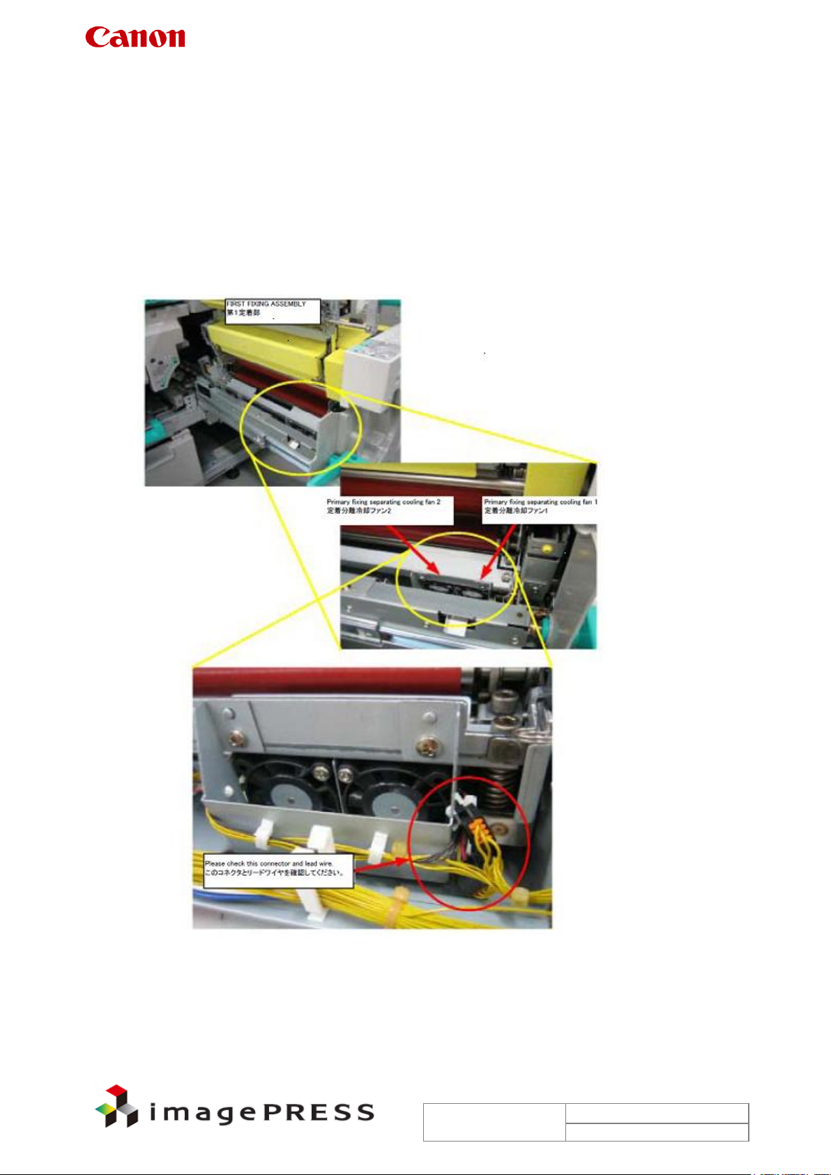
1.24 E805-0701
Description
There are some reported instances from the field where the error code ‘E805-0701’ was
indicated during a continuous copy job because the primary fixing separating cooling fan 1 had
wire pinching.
- E805-0701 can be displayed when an error occurs with the primary fixing separating cooling
fan 1. This error code is detected when the phase unlock state is detected for 2 sec
continuously 10 sec after the fan is turned on.
Field Remedy
1. Check the lead wire of connector on the primary fixing separating cooling fan 1 has NOT
been pinched.
4. If the lead wire has been pinched, repair it. If not, re-fit the connector.
5. If the symptom still occurs, re-fit J4372 and J4360 connectors of the primary fixing
internal driver PCB, J4080 and J4400 connectors of the fixing heater driver PCB 1, and
J1003 connector of the DC controller PCB.
6. If the symptom still occurs, replace the fan with a new one.
FK2-3148 Fan

Trouble Shooting Information for C7000VP series
Page 25
Rev. 2.0
2010/09/17
1.25 E822-0903
Description
There are some reported instances from the field where the error code ‘E822-0903’ was
indicated because a communication error occurred between the fixing duplex feed PCB and the
DC controller PCB 1-2 on the main station due to poor contact of the fixing duplexing drawer.
- E822-0903 can be displayed when the tandem guide lower cooling fan (FM358) causes an
error (sub station).
Field Remedy
1. Service mode > COPIER > Function > PART-CHK > FAN > enter '84' using the numeric
keys > OK > FAN-ON > check the operation of the fan. If the fan has no problem, it will
rotate for 10 sec at full speed.
2. If the fan does not rotate, re-fit the connector of the fan (FM358) to correct such a problem
as poor contact.
3. If the symptom still occurs, re-fit the fixing duplexing drawer connectors (fitted on the front
and back sides).
4. If the symptom still occurs, re-fit J4106 and J4070 connectors of the fixing duplex feed PCB,
and J1072 connector of the DC controller PCB 1-2.
5. If the symptom still occurs, replace the fan (FM358), the fixing duplex feed PCB, the DC
controller PCB 1-2 with new ones in this order.
FK2-3100 FAN
FM2-7700 Fixing Duplex Feed PCB Assembly
FM2-7686 DC Controller PCB 1-2 Assembly

Trouble Shooting Information for C7000VP series
Page 26
Rev. 2.0
2010/09/17
1.26 E020
E020-0x81
Error Description: Lower limit error in light intensity on drum base (reflecting light intensity from
the drum surface)
* COPIER > Display > DENS > P-B-P-Y/M/C/K is less than 150.
Cause of occurrence (Highly possible): Soil on the ATR sensor [*1]
Cause of occurrence (Low possible): Faulty pressure for developing assembly
Broken wire of ATR sensor
Damaged ATR sensor
Malfunction of ATR patch detection shutter
E020-0x82
Error Description: Lower limit error in current passed to the sensor while the patch sensor LED
is off
* COPIER > Display > DENS > P-D-P-Y/M/C/K is 30 or less.
Cause of occurrence (Highly possible): Broken wire of ATR sensor
Damaged ATR sensor
E020-0x84
Error Description: Fault at sampling drum base
* A difference between the values in service mode > COPIER > Display > DENS >
P-B-P-Y/M/C/K and P-D-P-Y/M/C/K is 30 or less.
Cause of occurrence (Highly possible): Soil on the ATR sensor [*1]
Cause of occurrence (Low possible): Faulty pressure for developing assembly
Broken wire of ATR sensor
Damaged ATR sensor
Malfunction of ATR patch detection shutter
E020-0x85
Error Description: Fault at sampling 1 in patch image
* A difference between the values in service mode > COPIER > Display > DENS >
DENS-S-Y/M/C/K and P-D-P-Y/M/C/K is 30 or less.
Cause of occurrence (Highly possible): Soil on the ATR sensor [*1]
Cause of occurrence (Low possible): Image density is too high.
Faulty pressure for developing assembly
Broken wire of ATR sensor
Damaged ATR sensor
Malfunction of ATR patch detection shutter
E020-0x86
Error Description: Fault at sampling 2 in patch image
* A difference between the values in service mode > COPIER > Display > DENS >
DENS-S-Y/M/C/K and P-B-P-Y/M/C/K is 30 or less.
Cause of occurrence (Highly possible): Image density is too low. [*2]
Cause of occurrence (Low possible): Soil on the ATR sensor
Faulty pressure for developing assembly
Broken wire of ATR sensor
Damaged ATR sensor
Malfunction of ATR patch detection shutter

Trouble Shooting Information for C7000VP series
Page 27
Rev. 2.0
2010/09/17
E020-0x87
Error Description: Upper limit error 2 in current passed to the sensor while the patch sensor
LED is off
* COPIER > Display > DENS > P-D-P-Y/M/C/K is 930 or more.
Cause of occurrence (Highly possible): Damaged ATR sensor
E020-0xC2
Error Description: Error in variation of sampling value in patch image
* When variation of sampling Sig values is 400 or more.
Cause of occurrence (Highly possible): Tiger stripe
Cause of occurrence (Low possible): Scratches on drum
E020-0x90
Error Description: Lower limit error in ATR patch image density
Cause of occurrence (Highly possible): Soil on the ATR sensor [*1]
Cause of occurrence (Low possible): Image density is too high.
Faulty pressure for developing assembly
Broken wire of ATR sensor
Damaged ATR sensor
Malfunction of ATR patch detection shutter
E020-0x91
Error Description: Upper limit error in ATR patch image density
* COPIER > Display > DENS > DENS-S-Y/M/C/K is more than 880.
Cause of occurrence (Highly possible): Image density is too low. [*2]
Cause of occurrence (Low possible): Soil on the ATR sensor
Faulty pressure for developing assembly
Broken wire of ATR sensor
Damaged ATR sensor
Malfunction of ATR patch detection shutter
E020-0x92
Error Description: Lower limit error in developer density
* COPIER > Display > DENS > DENS-S-Y/M/C/K is –4% or less 3 consecutive times.
Cause of occurrence (Highly possible): Image density is too low. [*2]
Cause of occurrence (Low possible): Soil on the ATR sensor
Faulty pressure for developing assembly
Broken wire of ATR sensor
Damaged ATR sensor
Malfunction of ATR patch detection shutter
E020-0x93
Error Description: Upper limit error in developer density
* COPIER > Display > DENS > DENS-S-Y/M/C/K is +4% or more 3 consecutive times.
Cause of occurrence (Highly possible): Soil on the ATR sensor [*1]
Cause of occurrence (Low possible): Image density is too high.
Faulty pressure for developing assembly
Broken wire of ATR sensor
Damaged ATR sensor
Malfunction of ATR patch detection shutter

Trouble Shooting Information for C7000VP series
Page 28
Rev. 2.0
2010/09/17
E020-0xB0
Error Description: Lower limit error in signal value of toner density sensor
* While printing, COPIER > Display > DENS > SGLL-Y/M/C/K is 64 or less for Y and 48 or less
for M/C/K for 5 prints continuously (T/D ratio is too high).
Cause of occurrence (Highly possible): Abnormal toner supply [*3]
Cause of occurrence (Low possible): Short circuit of harness for ATR sensor
Occurrence of Tiger stripe
E020-0xB1
Error Description: Upper limit error in signal value of toner density sensor
* While printing, COPIER > Display > DENS > SGLL-Y/M/C/K is 192 or more for Y and 126 or
more for M/C/K for 5 prints continuously (T/D ratio is too low).
Cause of occurrence (Highly possible): Disconnected connector of toner density sensor (or
poor contact)
Cause of occurrence (Low possible): Faulty sub hopper (no toner)
Damaged toner density sensor

Trouble Shooting Information for C7000VP series
Page 29
Rev. 2.0
2010/09/17
*1 Soil on the ATR sensor
Field Remedy
1. Clean the ATR sensor with alcohol.
Note: Wipe the sensor in one direction more than 3 times. Do NOT wipe it back-and-forth.
7. Replace the ATR sensor with a new one.
In addition, for the purpose of preventing any future occurrence, follow the steps below.
a. Service mode(Level 2) > COPIER > Adjust > DENS > HLMT-PTY/M/C/K,
Settings: If the current value is 4, change it to 9.
Note:
Density might decrease as a negative effect. Therefore, execute the above setting value
change only if soil on the sensor occurred at less than 250K intervals of periodic cleaning
maintenance for ATR sensor.
Or
b. Shorten the interval of cleaning maintenance.
If the current value is 9, change it to 10.
*2 Image density is too low
As possible causes of low image density, soiled primary charging assembly, faulty laser, soiled
dust-proof glass, faulty drum, faulty developing, and etc. are conceivable. However, faulty
developing is the most likely. For this reason, check the area around the developing assembly
first.
Field Remedy
1. Check the area around the developing assembly.
Are there occurrences of Tiger stripe?
Are there occurrences of developer overflow?
If these symptoms have occurred, replace the developer after taking actions such as
cleaning.
1. If there is no abnormality found at the step 1, output PG5 of the corresponding color
with density settings ‘80’ and ‘255’. Check the density and unevenness.
Trouble Shooting Information for C7000VP series
Page 30
Rev. 2.0
2010/09/17
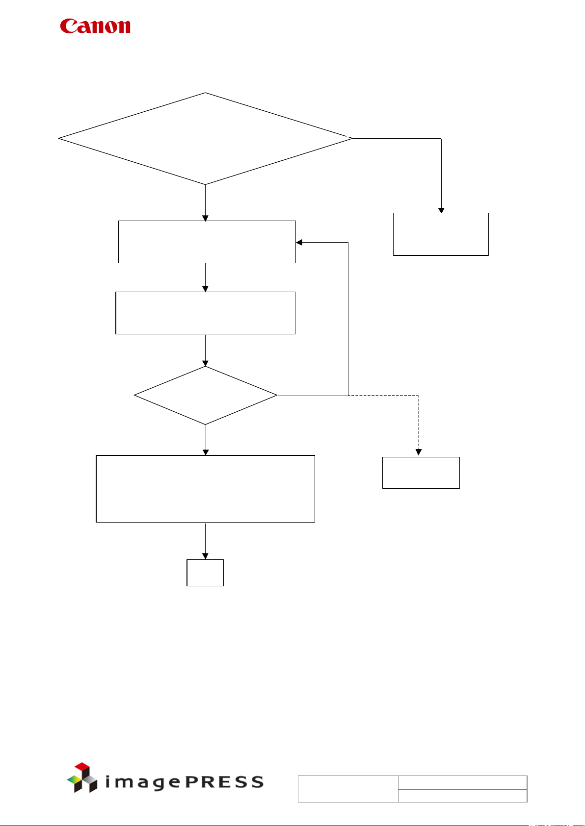
No
Yes
No
No improvement even after
repeating the left loop 3 times
・Feed 100 sheets of A3/LDR size or larger
for PG10
(200 sheets for A4/LTR)
Service mode
COPIER > Display > DENS > DENS-YMCK
Y +1or more
M/C/K +2 or more
Check
・Any occurrence of developer
overflow?
・Any occurrence of Tiger stripe?
Yes
・Replace developer
・Clean in the machine
Execute the above.
Replace
developing
assembly
- Service mode
COPIER > Adjust > DENS > HLMT-TY/M/C/K
Settings: If it is 4 at this point, change it to 9.
If it is 9 at this point, change it to 10.
Note: Density might decrease as a negative effect.
Finish
*3 Abnormal toner supply
 Loading...