

Canon imagePRESS C10000VPSeries Troubleshooting Manual

Troubleshooting Guide
imagePRESS
C10000VPSeries
July 16, 2019
Canon U.S.A., Inc.

New Arrival Information
[Regarding Troubleshooting Guide]
Please be advised of the release of Troubleshooting Guide for imagePRESS C10000VP series.
Troubleshooting Guide is a booklet compiled from FAQs issued by Canon Inc.
[Additional case(s)]
• Measures against poor image density on the ends of the front and rear sides of the image
• Fixing failure due to shaved belt tension plate
• 012A Jam code due to lack of strength in the decurler drive roller
• 10mm wide soiled edge at the leading edge due to components in toner on papers being attached
• 0119/011A jam code due to folded corner of paper edge
Trouble Shooting Guide will be issued in the future when we have a new issue/FAQ.

Contents
Image Faults......................................................................................................... 1
Faint white line on a second side image due to the stain on the Connection Lower Guide Roller
for the Primary Fixing Assembly......................................................................................................1
Uneven gloss (Rain drop mark) in the high-density area in usage of OHT......................................... 2
Horizontal white streaks with 2mm intervals on a high density green image...................................... 5
Uneven gloss on the entire high density image...................................................................................8
Glossy streaks on high density portion..............................................................................................11
10mm wide glossy lines near 40/80/10mm from the center of the first side of duplex printing......... 12
1 mm-wide glossy lines at intervals of 5 mm in the high-density area on the first side of duplex
printing...........................................................................................................................................14
Prevention method for random horizontal lines on a halftone image due to curled ITB from
being unused for a long time......................................................................................................... 17
Ring marks on an image due to the foreign substance contamination in the developing assembly.. 21
Error in reading image position adjustment caused by paper fault................................................... 22
Marks appear on the front side of the back face of one-sided print or of the first face of two-
sided print...................................................................................................................................... 24
Strike mark on the fixing roller due to toner soiling........................................................................... 25
Streaks on image due to an erroneous assemblage of the pressure refresh roller...........................26
Vertical lines due to cross feed roller pressure................................................................................. 27
Non-glossy lines with a width of 7 mm due to the life of fixing belt................................................... 28
White horizontal lines at intervals of 2mm on green high-density image caused by uneven
charge amount of the ITB.............................................................................................................. 29
Uneven density in a grid pattern on a high density image due to the uneven resistance on ITB......31
Soiling of spots at ITB intervals.........................................................................................................33
Soiled image on the 1st side of 2-sided print.................................................................................... 34
Soiled trailing edge/soiled paper edge on both sides of 2-sided print...............................................35
Vertical white line on solid image of each color.................................................................................36
Bk soiling at the front edge on the back side.....................................................................................38
Uneven density on a Bk solid image due to the uneven resistance of ITB....................................... 39
Uneven density on the second side of a black halftone image......................................................... 41
Edge Soiling due to a soiled fixing inlet guide...................................................................................43
Image failure occurring repeatedly at the same interval (xx pitch).................................................... 44
Stains on the back side of paper or uneven density at regular interval (5.0mm) due to the
scraped drive shaft when outputting an image.............................................................................. 46
Soiled edge on the leading edge and the trailing edge of paper caused by rubbing against the
flapper on the delivery reverse unit................................................................................................52
Uneven density on the second face of a halftone image due to uneven distribution of moisture
on paper surface............................................................................................................................53
Gloss lines on image due to the scratches on the surface of fixing roller which the refresh
roller gives in its operation.............................................................................................................55
Countermeasure against uneven density at 10mm intervals............................................................ 56
Marks on image caused by friction due to mini gripper edge (Perfect Binder- B1/D1/E1)................ 58
i

264mm drum pitch white band/ white spots and streaks on images due to scratches on cleaner
blade..............................................................................................................................................64
Stained image and uneven gloss due to breakage of torsion spring pressurizing the collection
roller...............................................................................................................................................66
Stain on back of papers and abnormal noise at the secondary transferassembly due to worn
out gears........................................................................................................................................71
Streaks and stains on image in feeding direction due to breakage of the tension spring................. 74
Stain on back of papers attributed to secondary transfer cleaning failure due to breakage of
cleaner front side plate.................................................................................................................. 76
Measures against poor image density on the ends of the front and rear sides of the image............ 83
Fixing failure due to shaved belt tension plate.................................................................................. 86
Faulty Feeding....................................................................................................91
Dog-eared corner of the leading edge of paper due to the curl.........................................................91
Measures for staple alignment failure (Staple-Q1/Saddle-AF2/AJ2/AK2/AM2/AN2/Booklet-
Q1/Finisher-AF1/AJ1/AK1/AM1/AN1)............................................................................................92
10mm wide soiled edge at the leading edge due to components in toner on papers being
attached.........................................................................................................................................98
Malfunction....................................................................................................... 107
The shaft support of the secondary transfer outer belt unit is not moved due to that the shaft
support is tilted when the releasing claw is pushed in.................................................................107
The secondary transfer outer belt and the outer belt tension roller holder breakage caused by
applied load................................................................................................................................. 108
Points to note when working on the surroundings of the halogen heater of fixing assembly.......... 115
Points to note when installing a lower entrance guide.................................................................... 123
Jam (Main Unit)................................................................................................ 124
0128 jam code due to high density image output in a high temperature/humidity environment......124
Measure against 0300JAM(wrong detection of double feed)at feeding of Washi (JPN Paper)...... 127
0114/0119 jam codes/abnormal sound due to the fixing assembly 86T gear with missing teeth....128
Measures when the display of jam 011B/0118/010F/021B/0218/020F/0A1B/0A18/0A0F
cannot be canceled (POD Deck Lite-B1/C1/Paper Deck Unit-E1/F1)......................................... 135
Measures against 012D jam occurrence.........................................................................................138
012A Jam code due to lack of strength in the decurler drive roller................................................. 147
0119/011A jam code due to folded corner of paper edge............................................................... 150
Jam (Delivery options).....................................................................................154
1004 Jam Code or folded corner on printed out paper due to positional displacement of
support (Staple/Saddle/Booklet/Finisher).................................................................................... 154
110F Jam code due to meshing failure of the timing belt (Staple-W1/Booklet-W1/Saddle-AN2/
Finisher-AN1)...............................................................................................................................156
1008 Jam Code due to nip failure of post card feeding rollers (Finisher) .......................................160
1014/1086/10B5/10E9/17B5/17E9 Jam codes due to softened spacer (Paper Folding Unit/
Document Insertion / Folding Unit).............................................................................................. 165
110F jam code due to meshing failure on timing belt of operation feed motor (M26) (Staple/
Saddle/Booklet/Finisher)..............................................................................................................169
ii

Error Code........................................................................................................ 173
Measure against power supply errors _ the harness routing list classified according to power
supply systems of 12V/24V/38V..................................................................................................173
E025-0x51 due to the continuous paper passing of entire solid image whose size is A3 or larger... 177
Remedy When E260-0Fxx (Power Supply Error in Multiple Locations) Occurs..............................178
E029-0x01 by the incorrect position of Shutter Solenoid or error of shutter slide lever.................. 183
E842-0051/0052 due to shift in position of the Secondary Fixing Delivery Lower Separation
Claws...........................................................................................................................................194
Precautions against an erroneous assemblage of the external heat unit........................................196
Points to note when installing, removing and cleaning the primary corona assembly.................... 198
Countermeasure against E060-0x01 or white line image................................................................202
E842-011x or the refresh roller does not work due to broken pieces of 16T/31T gear going
into the fixing pressure belt assembly..........................................................................................205
E023-0x00/E025-0x51/a white band due to damaged ball bearings in the developing drive rail
assembly......................................................................................................................................214
E018-010x/E029-4001 due to overload to the sliding part of the leading edge registration
patch sensor shutter.................................................................................................................... 217
E077-0001 caused by incomplete locking of the registration feed assembly..................................222
Information of proactive measure against E842-0x21.....................................................................223
E568-8002/Shaved gear tooth due to overloading with friction from sliding while the
estrangement rack is moving (Staple-Q1/W1/Booklet-Q1/W1/Saddle-AM2/AN2/Finisher-
AM1/AN1).................................................................................................................................... 224
E012-1080 due to the instable rotation of ITB drive (iPC8000VP)..................................................228
Points to note in replacing the fixing external heat belt or external heating assembly.................... 229
Notice of periodical replacement of the trimming blade and the heater (Glue vat unit)...................230
Measure against failure after system version upgrade (Multi Function Professional Puncher_A1).. 231
E5A3-808x/E5B5-8016 and 1FA9 jam code due to sliding failure of dust buffer (Perfect Binder-
A1/B1/C1/D1/E1)......................................................................................................................... 232
Specifications-Related.....................................................................................237
Announcement about checking the color sensor service label value on installation of the device.. 237
Notice of procedure to replace the transmission shaft inside the drum drive assembly..................239
Countermeasure against shaving on the shaft of the upper registration roller................................247
Points to note when attaching the pressure roller heater in the secondary fixing assembly........... 248
Notification about the changes in the upper cover and cover sheet for the 1st fixing assembly
and second fixing assembly and about their proper uses............................................................253
Points to note when attaching the inner cover 2 on the secondary transfer drive unit....................255
Controller Specification...................................................................................257
After installing Fiery Color Profile Suite, spectrometers cannot be detected. ( Print Server )......... 257
Synchronization fails when changing Paper size of existing paper catalog media. ( Print Server ).. 258
Cannot staple for multiple worksheets in Excel ( Print Server )...................................................... 259
Unexpected result of booklet job with External Finisher. ( imagePRESS Server B5100/B4100 )...260
iii
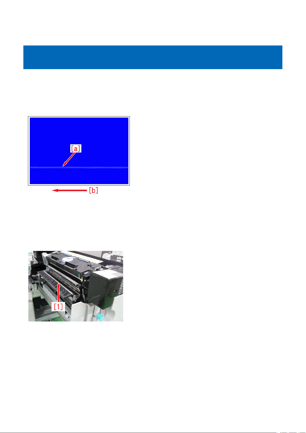
Image Faults
Faint white line on a second side image due to the stain on the Connection Lower Guide Roller for the Primary Fixing Assembly
[Symptom]
A faint white line [a] might appear on a second side image, if the machine is used a lot under the high temperature and high
humidity environment.
The arrow [b] indicates the direction of feeding.
The symptom is easily found on a high density image such as halftone or solid image.
[Cause]
IF the paper having a lot of paper lint is used under high temperature and high humidity environment, the paper lint and wax
component of toner combine and adhere to the Connection Lower Guide Roller [1] located at the outlet for the Primary Fixing
Assembly.
When the paper lint and the wax component of toner which adhere to the roller are transferred to a paper, the above symptom
occurs.
[Service work]
1) Open the Sub Station Front Right Cover to pull out the Primary Fixing Assembly.
2) Clean the whole surface of the Connection Lower Guide Roller with lint-free paper moistened with alcohol rotating the roller
by hand.
3) Output the image having shown the symptom, and check that the symptom does not occur.
If the symptom does not improve, then check other factors.
1

Uneven gloss (Rain drop mark) in the high-density area in usage of OHT
[Symptom]
Uneven gloss (Rain drop mark) [a] may occur in the high-density area in usage of OHT.
The arrow [b] indicates the direction of feeding.
[Cause]
Since the thickness and components of OHT vary depending on the kind, quantity of heat required for toner to fix on the film also
varies.
In case an excessive temperature is added on OHT, toner tends to melt beyond necessity.
The difference in glossiness made between the area where toner melts beyond necessity and the other image area causes the
above-mentioned symptom.
[Service work]
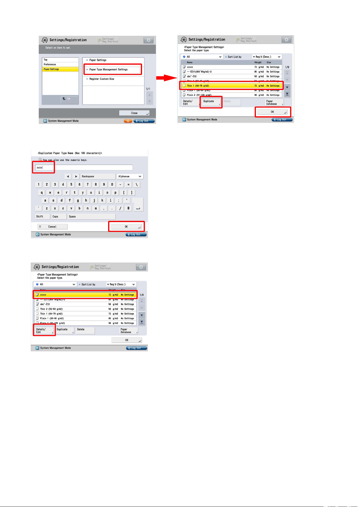
1) Have the customer log in from System Management Mode in user mode.
2) Go to Select Settings/Registration > Paper Settings > Paper Type Management Settings, select an appropriate paper type
from among the list, press "Duplicate" button and then "OK" button.
3) Enter any name as the duplicated paper type and press "OK" button.
2
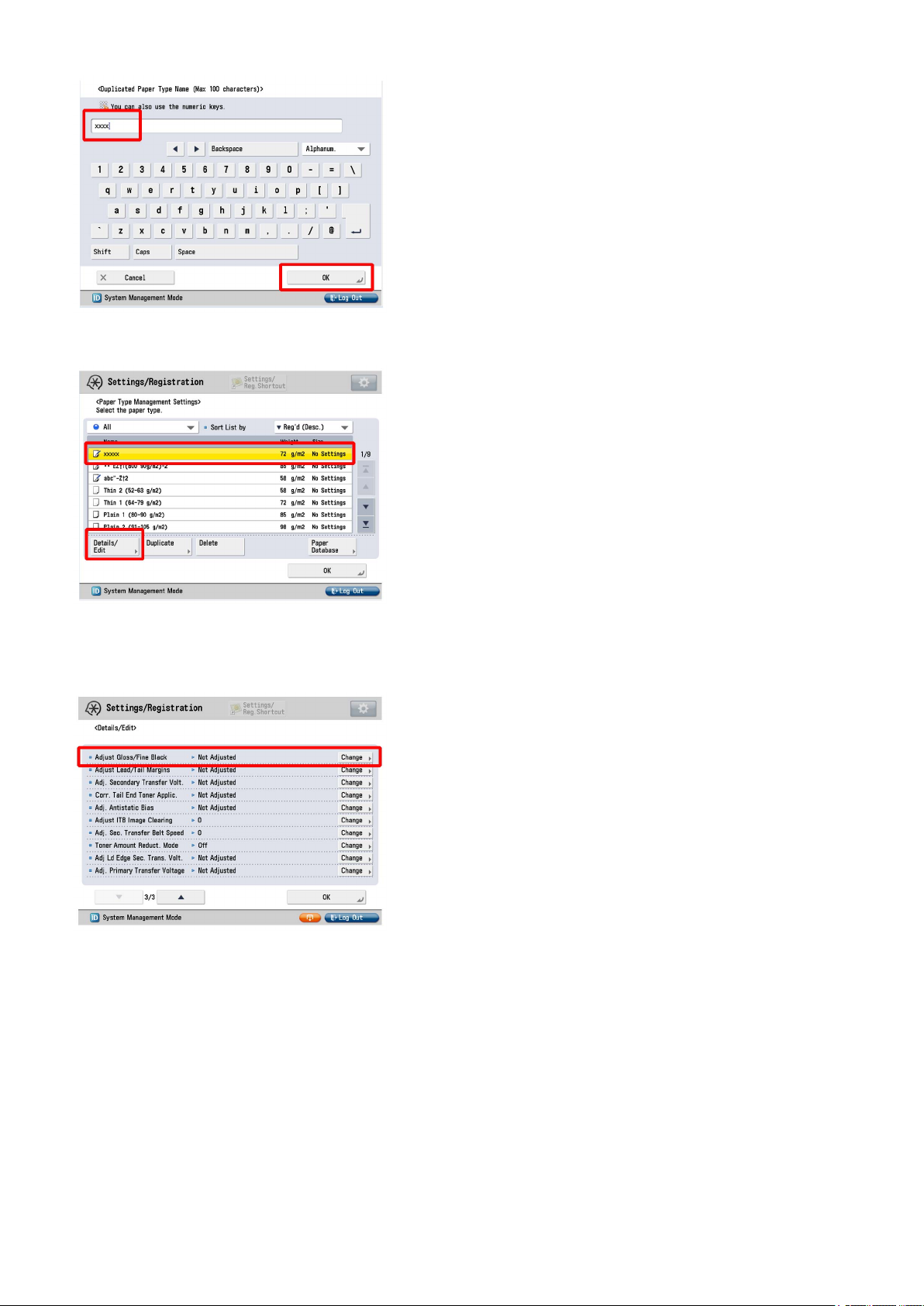
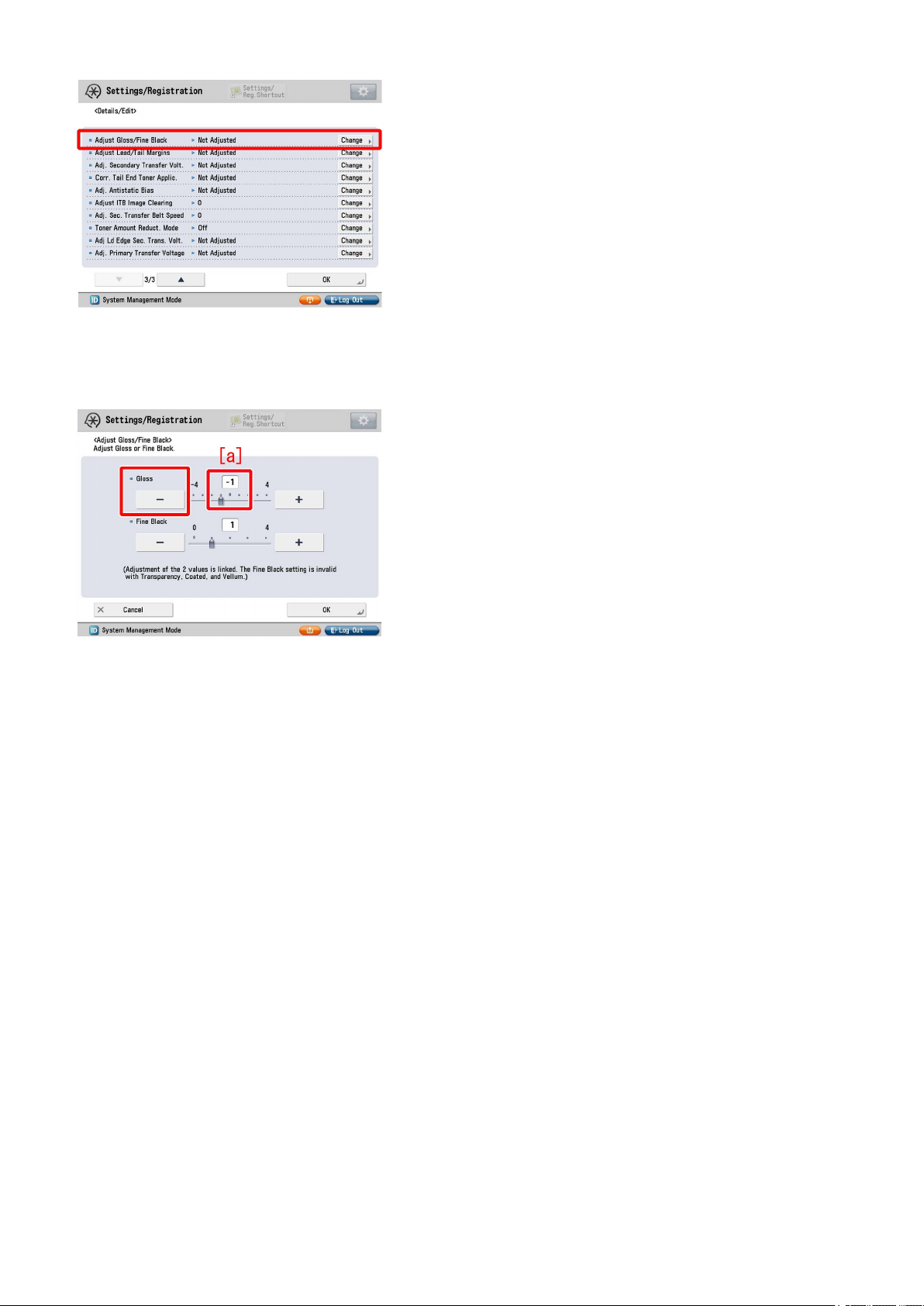
4) Select the paper type duplicated in the step 3) and press "Details/Edit".
5) Select "Adjust Gross/Fine Black" and press "Change".
[Reference] In case Adjust Gross/Fine Black will not be displayed on the control panel, change the setting value of Service Mode
> Mode List > COPIER > Option > DSPLY-SW > IMGC-ADJ to "1". The value is "0" by default.
6) Press "-" button for gloss, Make sure the setting value [a] is set to "-1" and press "OK".
The setting range is from "-4" to "+4" ("0" by default).
Change of the setting value changes the fixing temperature.
3

[Caution] Changing the value may cause glossiness of image may slightly decrease.
7 ) Output the image having shown the symptom, and check that the symptom does not occur.
If the symptom improvement is inadequate, decrease the setting value of step 6) down to "-3" by "1" value while observing the
symptom.
In case the decreased setting value "-3" of step 6) does not improve the symptom, please check another factor.
4
Horizontal white streaks with 2mm intervals on a high density green image
[Symptom]
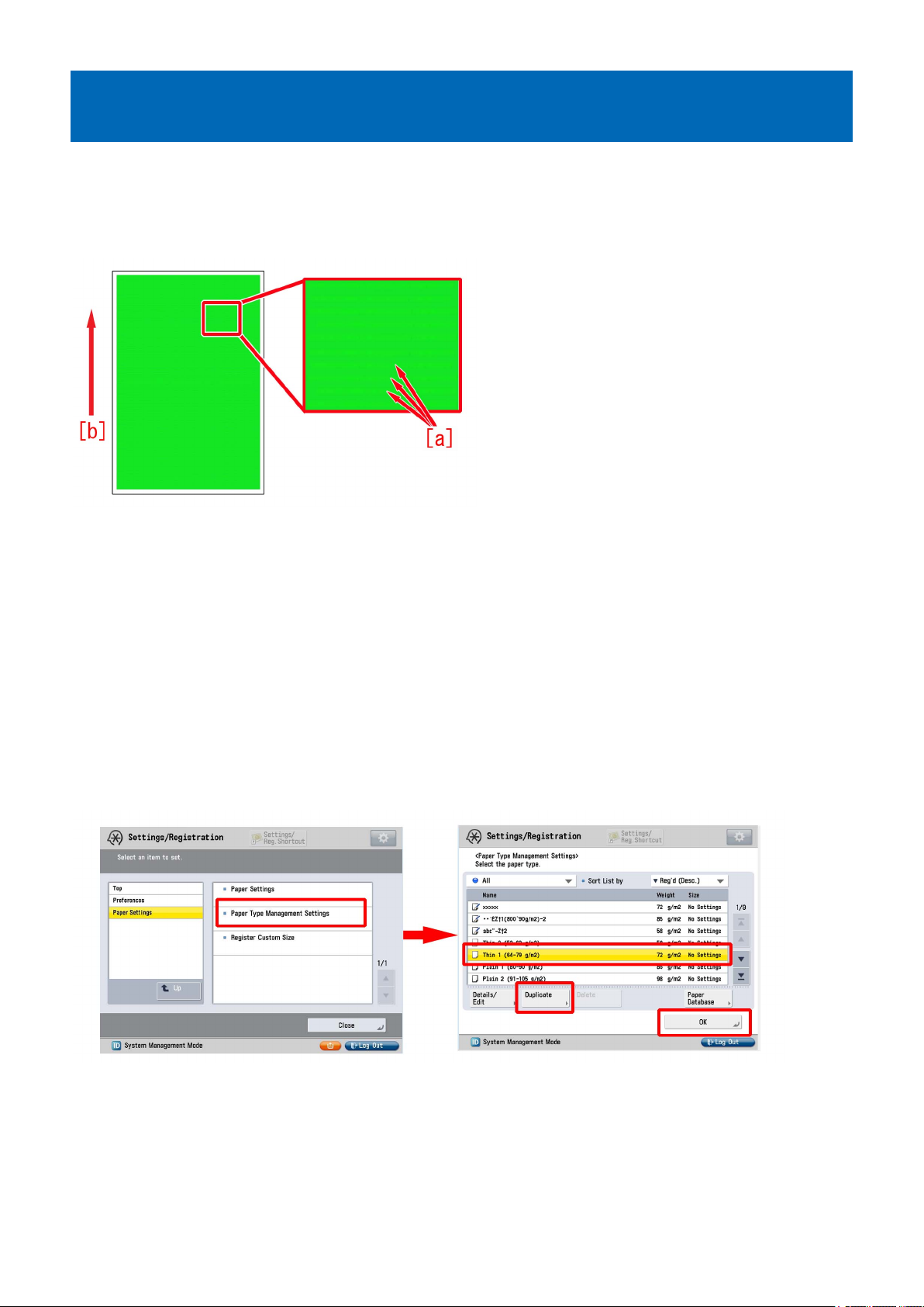
In a usage under a low humidity environment, horizontal white streaks [a] with 2mm intervals may occur on a high density green
image
The arrow [b] indicates the direction of feeding.
[Cause]
Being affected by the influence of toner or ITB, the electric current may become uneven even if a constant primary transfer voltage
is applied.
If an electrical discharge phenomenon is generated on a part where has more current after the transfer, the electric charge amount
varies among the toner on the paper.
When the electric charge amount varies, the amount of toner that was once transferred to paper and to be attracted to the drum
(retransfer) at the next station changes, so that the toner amount on the paper becomes uneven and results in the above
mentioned symptom.
A low humidity environment is likely to have this symptom as the primary transfer voltage is large.
[Service work]
1) Have the customer log in from System Management Mode in user mode.
2) Go to Select Settings/Registration > Paper Settings > Paper Type Management Settings, select an appropriate paper type
from among the list, press "Duplicate" button and then "OK" button.
3) Enter any name as the duplicated paper type and press "OK" button.
5
4) Select the paper type duplicated in the step 3) and press "Details/Edit".
5) Select "Adj. Primary Transfer Voltage" and press "Change".
[Reference] In case Adjust Primary Transfer Voltage will not be displayed on the control panel, change the setting value of Service
Mode > Mode List > COPIER > Option > DSPLY-SW > IMGC-ADJ to "1". The value is "0" by default.
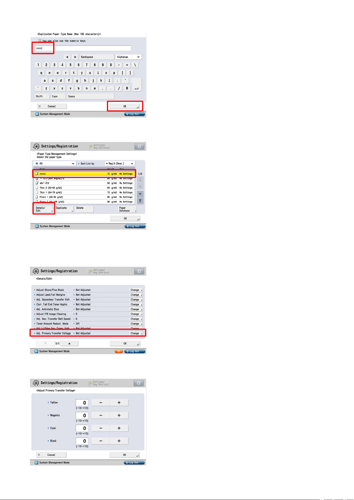
6) If the Adjust Primary Transfer Voltage screen is displayed, the presetting is completed.
6

7) Select black under primary transfer voltage, change the correction parameter [a] to "-5" by pressing "-" button and press "OK".
The setting range is from "-10" to "+10 ". ("0" by default)
Change of the setting value changes the primary transfer voltage.
[Caution] Changing this setting may decrease the primary transfer voltage and bring poor image with black (lowering of density,
mottling image, etc.).
8) Output the image having shown the symptom, and check that the symptom does not occur.
If the symptom does not improve, then check other factors.
7

Uneven gloss on the entire high density image
[Symptom]
Uneven gloss [a] may occur on the entire high density image such as solid image.
The arrow [b] indicates the direction of feeding.
[Cause]
The influence of an uneven temperature and uneven cooling of the member (guide etc.) on the delivery path after fixing may
cause the time difference in solidifying the wax components included in the toner.
When there is the time difference in solidifying the wax components, the difference in glossiness on the image surface tends to
stand out, and the above-mentioned symptom occurs.
This symptom is likely to be seen on the high density image with high quantity of toner and heavy paper/coated paper that is fixed
at a high temperature.
[Service work]
1) Have the customer log in from System Management Mode in user mode.
2) Go to Select Settings/Registration > Paper Settings > Paper Type Management Settings, select an appropriate paper type
from among the list, press "Duplicate" button and then "OK" button.
3) Enter any name as the duplicated paper type and press "OK" button.
8

4) Select the paper type duplicated in the step 3) and press "Details/Edit".
5) Select "Adjust Gross/Fine Black" and press "Change".
[Reference] In case Adjust Gross/Fine Black will not be displayed on the control panel, change the setting value of Service Mode
> Mode List > COPIER > Option > DSPLY-SW > IMGC-ADJ to "1". The value is "0" by default.
6) Press "-" button for gloss, Make sure the setting value [a] is set to "-1" and press "OK".
The setting range is from "-4" to "+4" ("0" by default).
Change of the setting value changes the fixing temperature.
9

[Caution] Changing the value may cause glossiness of image may slightly decrease.
7 ) Output the image having shown the symptom, and check that the symptom does not occur.
If the symptom improvement is inadequate, decrease the setting value of step 6) down to "-3" by "1" value while observing the
symptom.
In case the decreased setting value "-3"of step 6) does not improve the symptom, please check another factor.
10
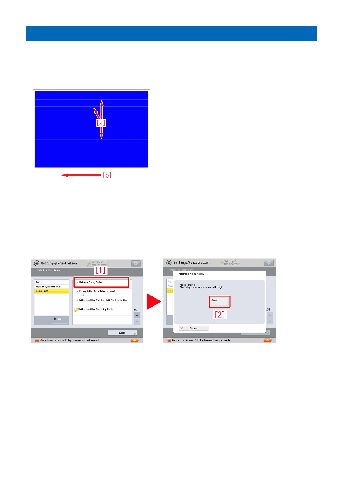
Glossy streaks on high density portion
[Symptom]
Glossy streaks [a] may appear on a high density portion.
The arrow [b] indicates the direction of feeding.
This symptom is more visible with heavy / coated paper.
[Cause]
The surface of the fixing roller may have minute scratches on it due to foreign particles such as paper lint.
The thermal conductance of the scratched portion of the fixing roller is lower than that of surrounding portions and the glossiness
of image of the same portion is reduced.
The difference of the glossiness of the image generates the aforementioned symptom.
[Service work]
1) Select Settings/Registration > Adjustment/Maintenance > Maintenance > Refresh Fixing Roller[1],and press "Start" button[2].
[Reference] The time required for adjustment is approximate 40 seconds.
2) Output the image having shown the symptom, and check that the symptom does not occur. If the symptom no longer occurs,
the work is completed.
If the symptom will not improve, repeat the step 1) for thrice.
3) Output the image having shown the symptom, and check that the symptom does not occur.
If the symptom does not improve, check other causes.
11
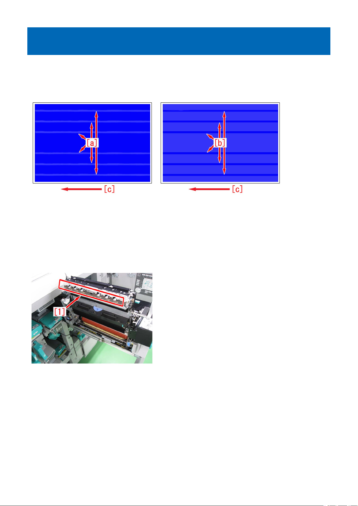
10mm wide glossy lines near 40/80/10mm from the center of the first side of duplex printing
[Symptom]
10 mm wide semi-glossy lines [a] and highly glossy lines [b] may occur at one of near 40, 80, and 120 mm from the center on
the first side of duplex printing.
The arrow [c] indicates the direction of feeding.
[Cause]
The secondary fixing assembly separates thin papers by engaging the fixing separation claw [1] to the pressure roller.
a. when the surface of the pressure roller is lightly scratched by the fixing separation claw, glossiness of the area where the fixing
separation claw comes in contact with decreases and 10mm semai-glossy lines occur. The symptom tends to occur easily when
the pressure roller is new.
b. The pressure roller in the secondary fixing assembly may be polluted in some cases due to paper and/or toner scattering inside
the engine. The pollution is cleaned in the area where the fixing separation claw comes in contact with, so the glossiness is higher
compared to the area where the claw does not come in contact with, causing the 10mm wide highly glossy lines to occur.
[Service work]
1) Depending on the issue, choose and perform one of a) or b) below.
a) When 10mm wide semi-glossy lines occur:
a-1) Select Service mode > Mode List > COPIER > Function > CLEANING > [FX-CLN], and then press the "OK".
[Reference] The time required for adjustment is approximate 1 minute.
[Caution]
- Do not perform more than two times consecutively. Scratches of the pressure roller may get worse.
- When performed too often, the pressure roller and the pressure refresh roller worn out early.
a-2) Output the image having shown the symptom, and check that the symptom does not occur.
If the symptom does not improve, then check other factors.
b) When 10mm wide highly glossy lines occur:
b-1) Select Service mode > Mode List > COPIER > Function > CLEANING > [FX2PR-CL], and then press the "OK".
12

[Reference] The time required for adjustment is approximate 2 minute.
[Caution] When performed too often, the pressure roller and the pressure refresh roller worn out early.
b-2) Use heavy paper over 151gsm or coated paper over A3/LDR and perform the following: Service mode > Mode List > COPIER
> Test > Printabout10 sheets of duplex Yellow solid "PG ".
b-3) Output the image having shown the symptom, and check that the symptom does not occur.
If the symptom does not improve, then check other factors.
13
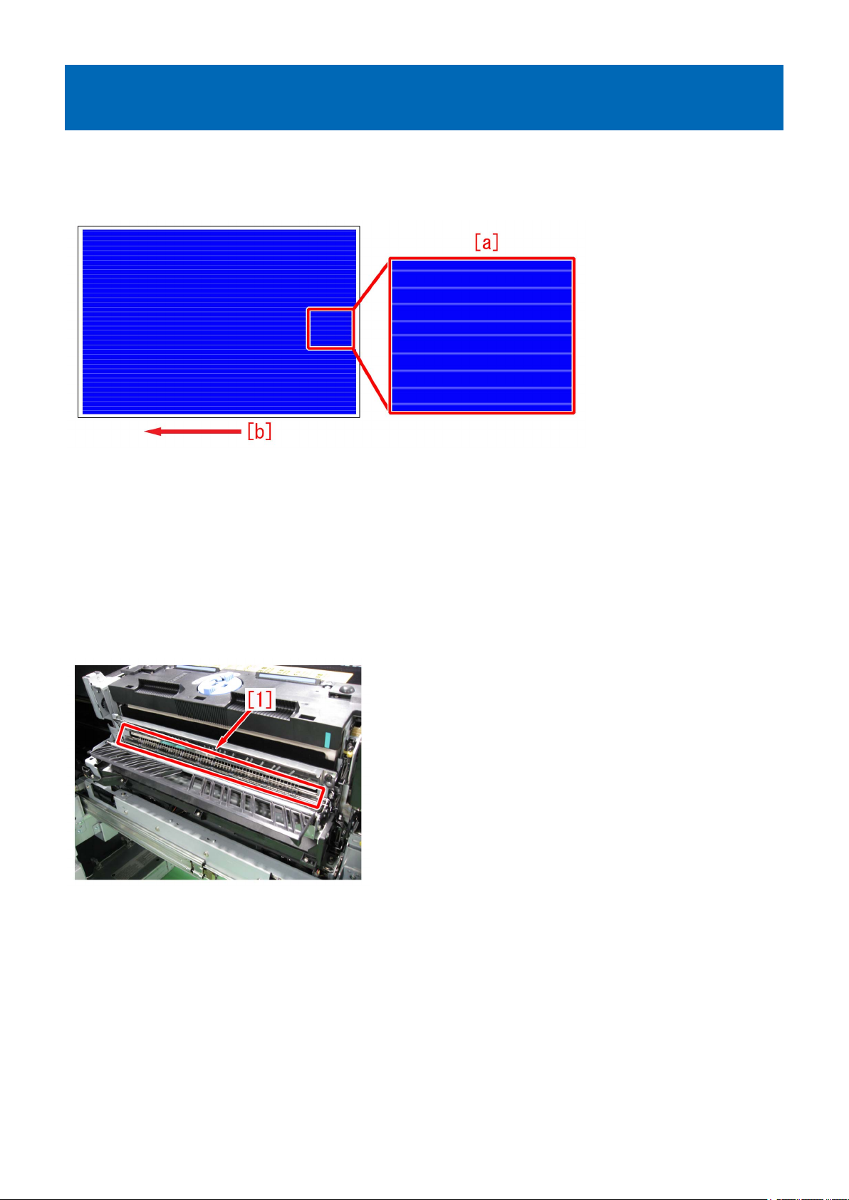
1 mm-wide glossy lines at intervals of 5 mm in the high-density area on the first side of duplex printing
[Symptom]
Several 1 mm-wide glossy lines [a] may occur at intervals of 5 mm in the high-density area on the first side of duplex printing.
The arrow [b] indicates the direction of feeding.
[Cause]
After heavy usage, toner may adhere to static eliminator located at the outlet of the first fixing assembly. If toner adheres to the
static eliminator, the static eliminator becomes firm and it rubs the image surface, and the above-mentioned symptom occurs.
This symptom can be seen more clearly on the high-density image having larger quantity of toner.
This symptom cannot be seen clearly on the heavy paper / coated paper since the paper is fixed again in the secondary fixing
assembly.
[Service work]
1) Open the sub station front right cover and take out the first fixing assembly.
2) Fold the five-ply lint-free paper in four, and clean the static eliminator [1] to become unraveled.
3) Insert the first fixing assembly and close the sub station front right cover.
4) Output the image having shown the symptom, and check that the symptom does not occur.
If the symptom no longer occurs, the work is completed.
If the improvement of the symptom is not enough, go to step 5).
5) Have the customer log in from System Management Mode in user mode.
6) Go to Select Settings/Registration > Paper Settings > Paper Type Management Settings, select an appropriate paper type
from among the list, press "Duplicate" button and then "OK" button.
14
7) Enter any name as the duplicated paper type and press "OK" button.
8) Select the paper type duplicated in the step 7) and press "Details/Edit".
9) Select "Adjust Gross/Fine Black" and press "Change".
[Reference] In case Adjust Gross/Fine Black will not be displayed on the control panel, change the setting value of Service Mode
> Mode List > COPIER > Option > DSPLY-SW > IMGC-ADJ to "1". The value is "0" by default.
15
10) Press "-" button for gloss, Make sure the setting value [a] is set to "-1" and press "OK".
The setting range is from "-4" to "+4" ("0" by default).
Change of the setting value changes the fixing temperature.
[Caution] Changing the value may cause glossiness of image may slightly decrease.
11 ) Output the image having shown the symptom, and check that the symptom does not occur.
If the symptom improvement is inadequate, decrease the setting value of step 10) down to "-3" by "1" value while observing the
symptom.
In case the decreased setting value "-3"of step 10) does not improve the symptom, please check anotherfactor.
16
Prevention method for random horizontal lines on a halftone image due to curled ITB from being unused for a long time
[Symptom]
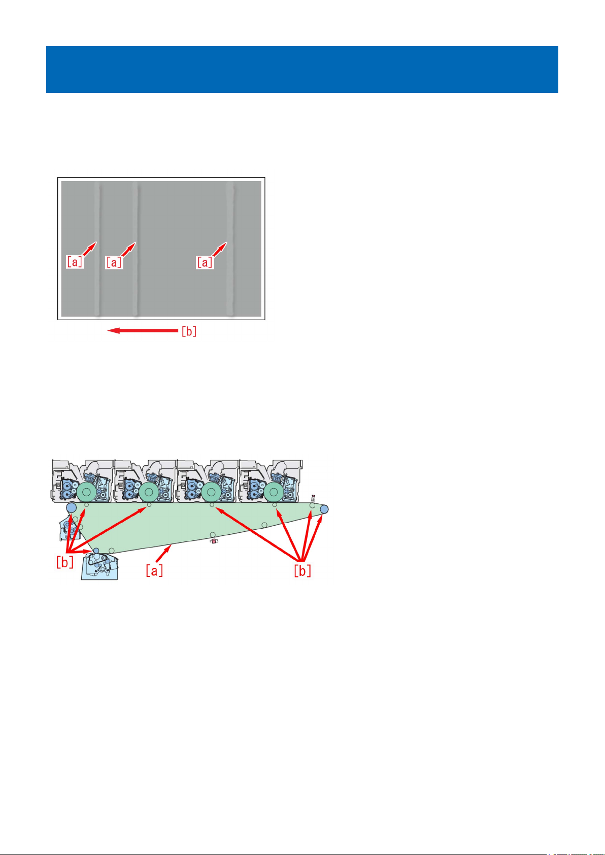
Horizontal lines [a] may appear randomly on a halftone image after leaving the machine for a long time.
The symptom is especially visible in 250mm intervals attributable to a primary transfer roller.
The arrow [b] indicates the direction of feeding.
[Cause]
If a machine is left untouched for a long time, ITB[a] and 8 rollers[b] inside ITB are in contact each other for a long time, and this
condition curls ITB.
The curled part makes tiny space between ITB and the secondary transfer outer roller, therefore discharge phenomenon may be
generated.
If discharge phenomenon is generated, toner on ITB scatters, disarranges the image and this results in the above mentioned
symptom.
[Service work]
The ITB that is curled from being unused for a long time cannot be fixed in a short time. If an ITB is left unused frequently, take
one of the two following measures, a) or b), to prevent ITB from being curled.
a) If ITB is left unused for a long time with the main power ON:
The ITB is rotated every certain period of time to prevent the symptom.
a-1) Go to Service mode (Lv2) > Mode List > COPIER > Option > IMG-TR > and change the setting value of "ITB-MOVE" to "3".
The setting range is from "0" to "10" ("0" by default).
rotated about 60mm every certain period of time.
[Reference] Explain to the customer that the operation noise can be heard even in Sleep (Deep sleep) mode because the service
mode runs every certain period of time.
b) If ITB is left unused for a long time with the main power OFF:
The pressure of the primary transfer roller is released to prevent the symptom.
[Caution]
17
- When starting to use the machine, apply a pressure to the primary transfer roller first. If not, an image failure (poor transfer)
would occur.
- There is no effect on the four locations other than the primary transfer roller.
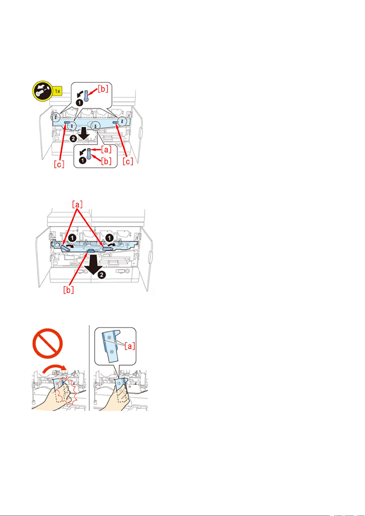
b-1) Open the Main Station Front Right Cover and the Main Station Front Left Cover.
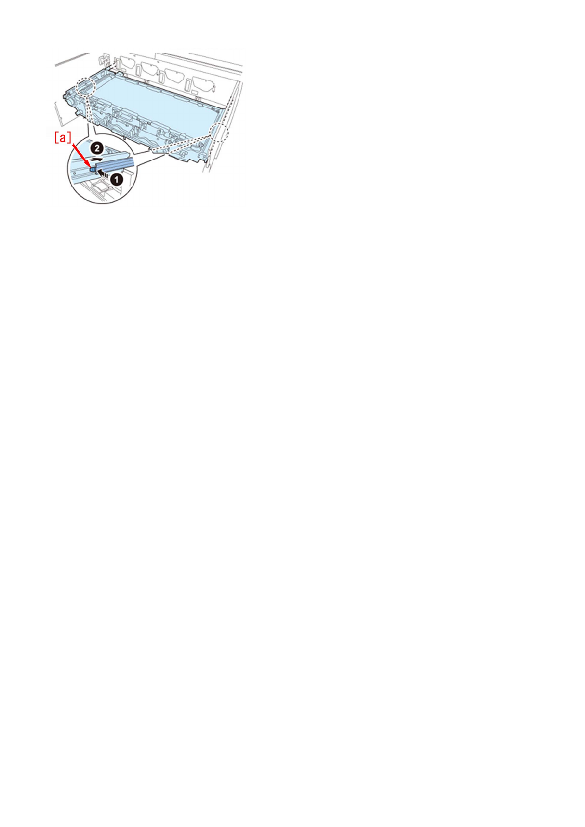
b-2) Remove the stepped screw (yellow)[a] and turn the 4 Release Levers [b] in the direction of the arrow, Holding the 2 grips[c],
remove the Intermediate Transfer Unit Cover
b-3) Turn the 2 Release Levers [a] of the Intermediate Transfer Unit in the direction of the arrow at the same time, and pull the
Intermediate Transfer Unit out until it stops by holding the grips[b].
[Caution] Be sure to hold only the [a] part of the ITB Release Levers when turning the ITB Release Levers, or your hand may be
pinched.
b-4) Holding the 2 grips [a] with both hands, lift the Intermediate Transfer Unit approx. 40 degrees and then lower it to the lock
position (approx. 30 degrees).
18
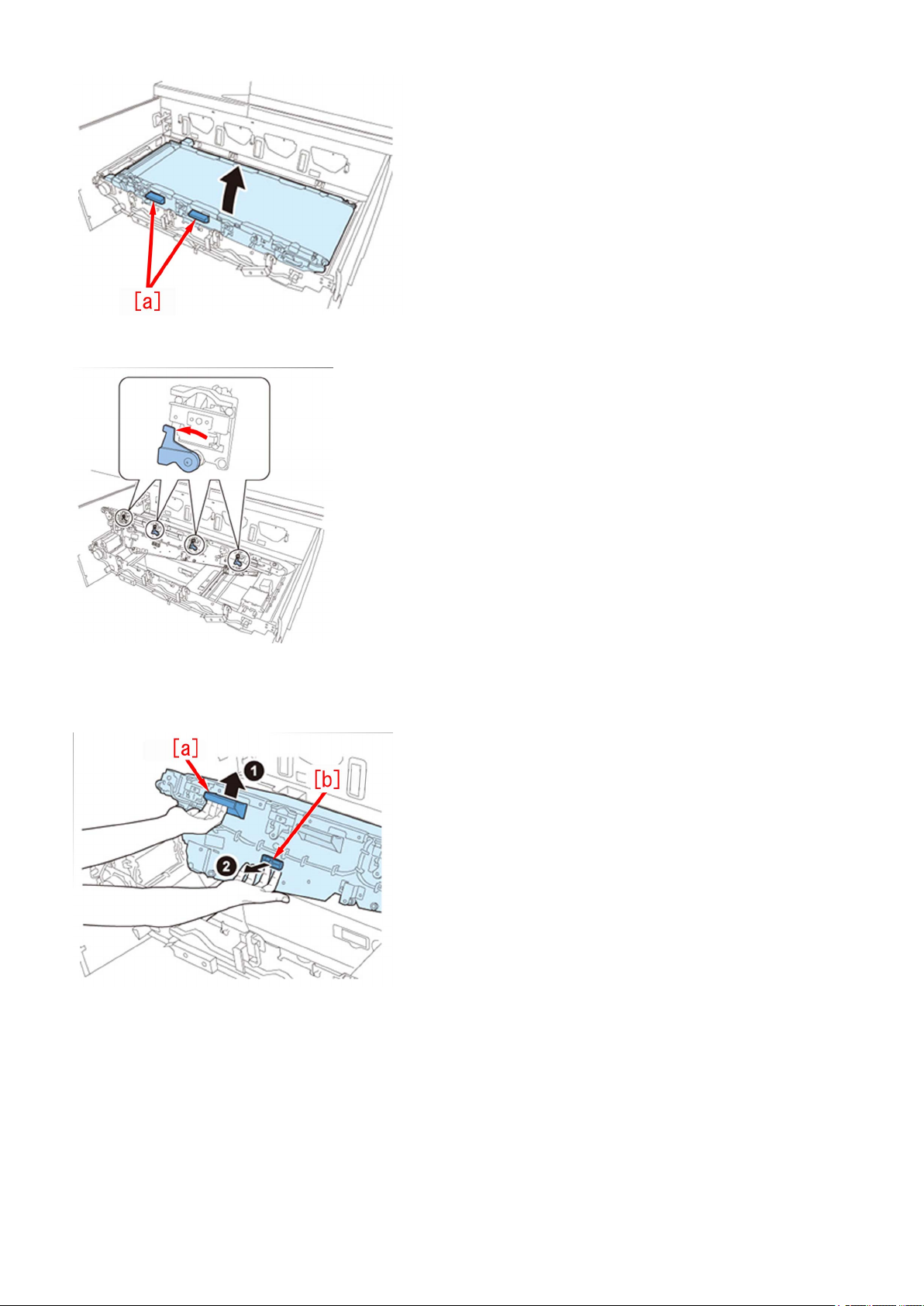
b-5) Rotate the 4 Primary Transfer Roller Pressure Release Levers anticlockwise to disengage.
b-6) Holding the grip [a], pull the Release Lever [b] until it stops while lifting the Intermediate Transfer Unit. While pulling the
Release Lever, lower the Intermediate Transfer Unit until it passes through the lock position (approx. 30 degrees), and release
both hands (the Intermediate Transfer Unit will lower slowly).
[Caution] Do not insert your hands etc. into the Intermediate Transfer Unit or Intermediate Transfer Unit Frame when lowering
the Intermediate Transfer Unit.
b-7) While pushing the 2 Lock Release Springs [a], slide the Intermediate Transfer Unit toward the rear side until the lock is
released.
19
[Caution] Be careful not to get your fingers caught when sliding the Intermediate Transfer Unit toward the rear side.
b-8) Perform the work in the reverse order from the step b-3).
20

Ring marks on an image due to the foreign substance contamination in the developing assembly
[Symptom]
In the machines prior to the Countermeasure cut-in serial number in factory described below due to an inevitable mixing of foreign
particles, a faulty image called a ring mark may be output on the print.
[Cause]
The metal powder mixed into the developing assembly attaches onto the surface of the developing sleeve and brings a leakage
symptom to the drum. Toner attaches onto the leaked location and this leads to the aforementioned symptom.
[Service work]
When the above mentioned symptom has occurred, follow the steps below.
a) When the main unit is already installed.
1) Service mode (level 2) : COPIER>Option>IMG-DEV>ADJVPP-M/C/K, change the parameter from "-1" to "-4".
[Caution] As the ring mark has never been observed with yellow color, do not change the parameter of ADJVPP-Y from "-1".
2) Execute the auto gradation adjustment.
b) When the main unit is not installed yet.
Perform the following installation work to install the main unit.
1) Execute the service mode (level 1) : COPIER>FUNCTION>INSTALL>AINR-OFF.
2) Service mode (level 2) : COPIER>Option>IMG-DEV>ADJVPP-M/C/K, change the parameter from "-1" to "-4".
[Caution] As the ring mark has never been observed with yellow color, do not change the parameter of ADJVPP-Y from "-1".
3) Perform the works from the step 2) described in the installation procedure.
[Countermeasure cut-in serial numbers in factory]
iPR C10000VP Series US : WBC00532
iPR C10000VP Series EU/O : WEJ00530
21
Error in reading image position adjustment caused by paper fault
[Symptom]
When executing the image position adjustment by using the scanner, "Correctly place the test page on the platen glass" may be
displayed at the time of reading the test page.
[Reference] Image position adjustment mode
User Mode > Preferences > Paper Settings > Paper Type Management Settings > Image Position Adjustment > Select Method
"Use Scanner"
[Cause]
If the paper edge used for the test page is not at a right angle due to trimming failure or being folded or if transfer failure occurs
on the test page image, it is regarded as faulty image at the time of reading the test page and the above-mentioned symptom
occurs.
[Service work]
1) Check the condition and image of the test page paper used for adjustment.
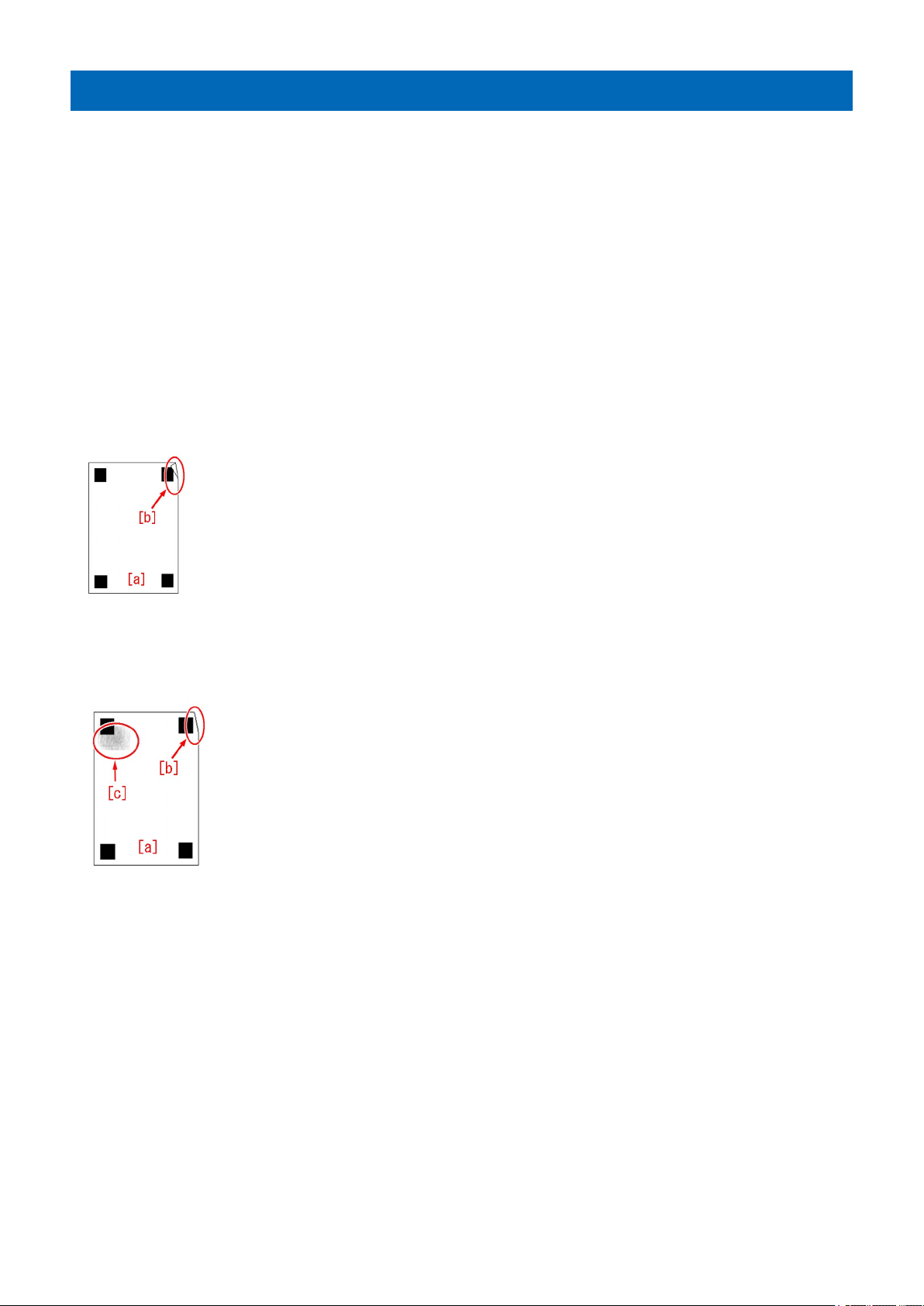
2) If the test page paper is not at a right angle,
2-1) if the paper [a] edge is folded [b], correct the fold and perform reading again.
2-2) if the paper [a] edge is lost due to trimming failure or damage [b] or if the test page image gets dirty [c], cancel the image
position adjustment, output test page using the new paper without trimming failure, and execute the image position adjustment
again.
3) If there is transfer failure [b] on the test page [a] image, cancel the image position adjustment, execute auto adjust gradation
and adjust the secondary transfer voltage, and then output the test page using the new paper to execute the image position
adjustment again.
User Mode "Settings/Registration > Adjustment/Maintenance > Adjust Image Quality > Auto Adjust Gradation > Full Adjust"
User Mode "Settings/Registration > Preferences > Paper Settings > Paper Type Management Settings > Adjust Secondary
Transfer Voltage"
22

4) If the symptom does not improve, then check other factors.
23
Marks appear on the front side of the back face of one-sided print or of the first face of two-sided print
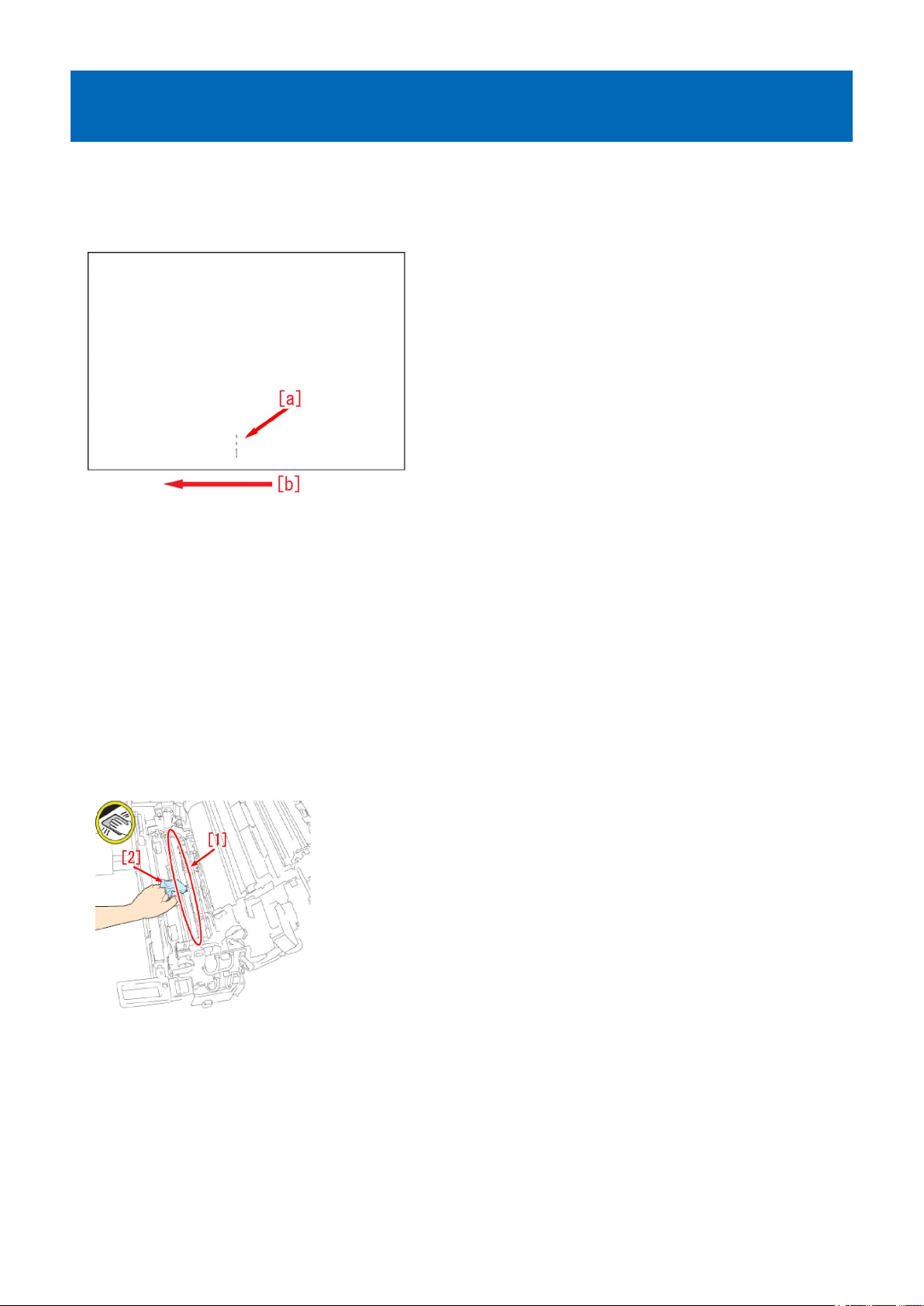
[Symptom]
Marks may appear on the front side [a] of the back face of one-sided print or of the first page of two-sided print.
The arrow [b] indicates the direction of feeding.
[Cause]
Paper dust or toner may attaches onto the pressure belt of the primary fixing assembly from the influence of the paper or toner
scattering inside the machine.
At that time, if the pressure belt displacement control is executed, the fixing belt comes in contact with the belt pressure shaft,
and paper dust and toner attach onto the belt pressure shaft.
When hundreds of thousands or more of sheets of paper has passed through the device, the paper dust or toner piled up on the
belt pressure shaft increases and it may move to the pressure belt during the pressure belt displacement control.
Paper dust and toner moved to the pressure belt attaches onto the paper, and this brings on the aforementioned symptom.
[Service work]
1) Remove the primary fixing pressure belt unit referring to "Disassembly/Assembly > Fixing System > Replacing the Primary
Fixing Pressure Belt Unit" in the service manual.
2) Clean the primary fixing belt pressure shaft and the adjacent shaft [1] with lint free paper moistened with alcohol [2].
3) Reassemble the primary fixing pressure belt unit in reverse order from the step 1).
4) Output the image having shown the symptom, and check that the symptom does not occur.
If the symptom does not improve, check other causes.
24
Strike mark on the fixing roller due to toner soiling
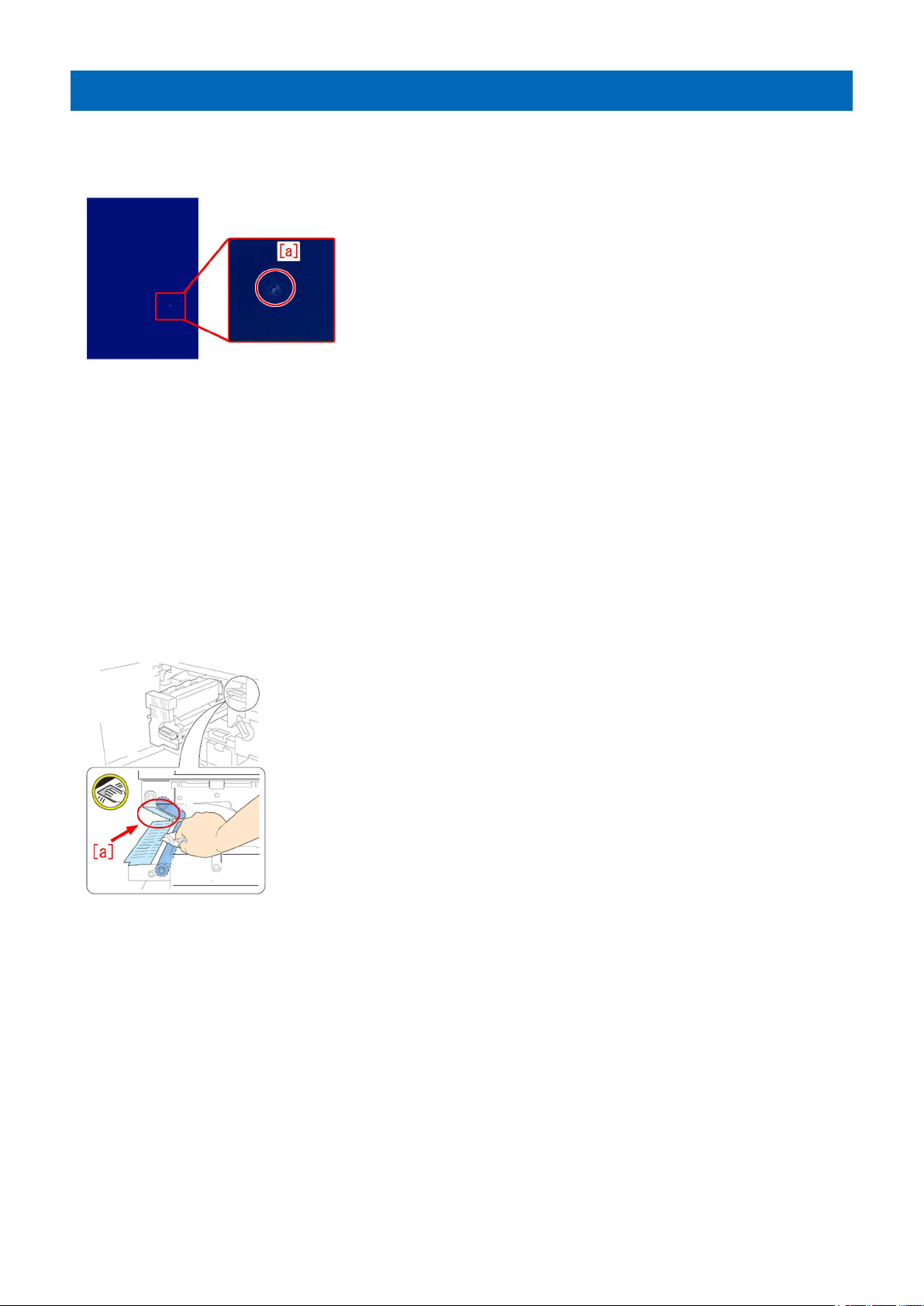
[Symptom]
Strike mark [a] may appear on the image. The symptom is easily found on a high density image such as halftone or solid image.
[Cause]
When printing, the upper tandem guide and paper interfere with each other. As a result, toner peels from the paper and
accumulates on the upper tandem guide. The above symptom may occur when a toner lump accumulated on the upper tandem
guide peels and falls, and then is transferred by paper and finally attaches to the secondary fixing roller.
[Service work]
1) Follow the steps in Service Manual "Disassembly / Assembly > Fixing System > Replacing the Secondary Fixing Roller,
Replacing the Secondary Fixing External Heat Belt, Replacing the Secondary Fixing Refresh Roller" and replace the Fixing Roller
(FL1-1152-000), the External Heat Belt, (FE3-1881-000) and the Refresh Roller Assembly (FM3-2876-000) in the Secondary
Fixing Assembly.
2) Check the upper tandem guide [a] and if toner is attached, follow the steps in Service Manual "Disassembly / Assembly >
Fixing System > Cleaning the Tandem Guide" and wipe the toner with lint-free paper soaked in alcohol.
3) Output the image having shown the symptom, and check that the symptom does not occur.
[Reference] At the time of regular replacement of the secondary fixing roller, check the upper tandem guide and wipe the toner
if any is attached.
[Service part]
FL1-1152 ROLLER, FIXING
FE3-1881 BELT, FIXING EXTERNAL HEAT
FM3-2876 ROLLER, REFRESH ASSEMBLY
25
 Loading...