

Canon imageCLASS MF6580CX, imageCLASS MF6580, imageCLASS MF6550, imageCLASS MF6530 Starter Guide
Page 1
Starter Guide
Please read this guide before operating this equipment.
After you finish reading this guide, store it in a safe place for future reference.
Series
ENG
Page 2
Set Up the Machine
Unless otherwise mentioned, illustrations used in this manual are those taken when no optional
equipment is attached to the MF6580, and also the menus described in this manual are based on the
model MF6580.
Depending on the model of your machine, some settings may not be available and the number on the
top of each menu may vary.
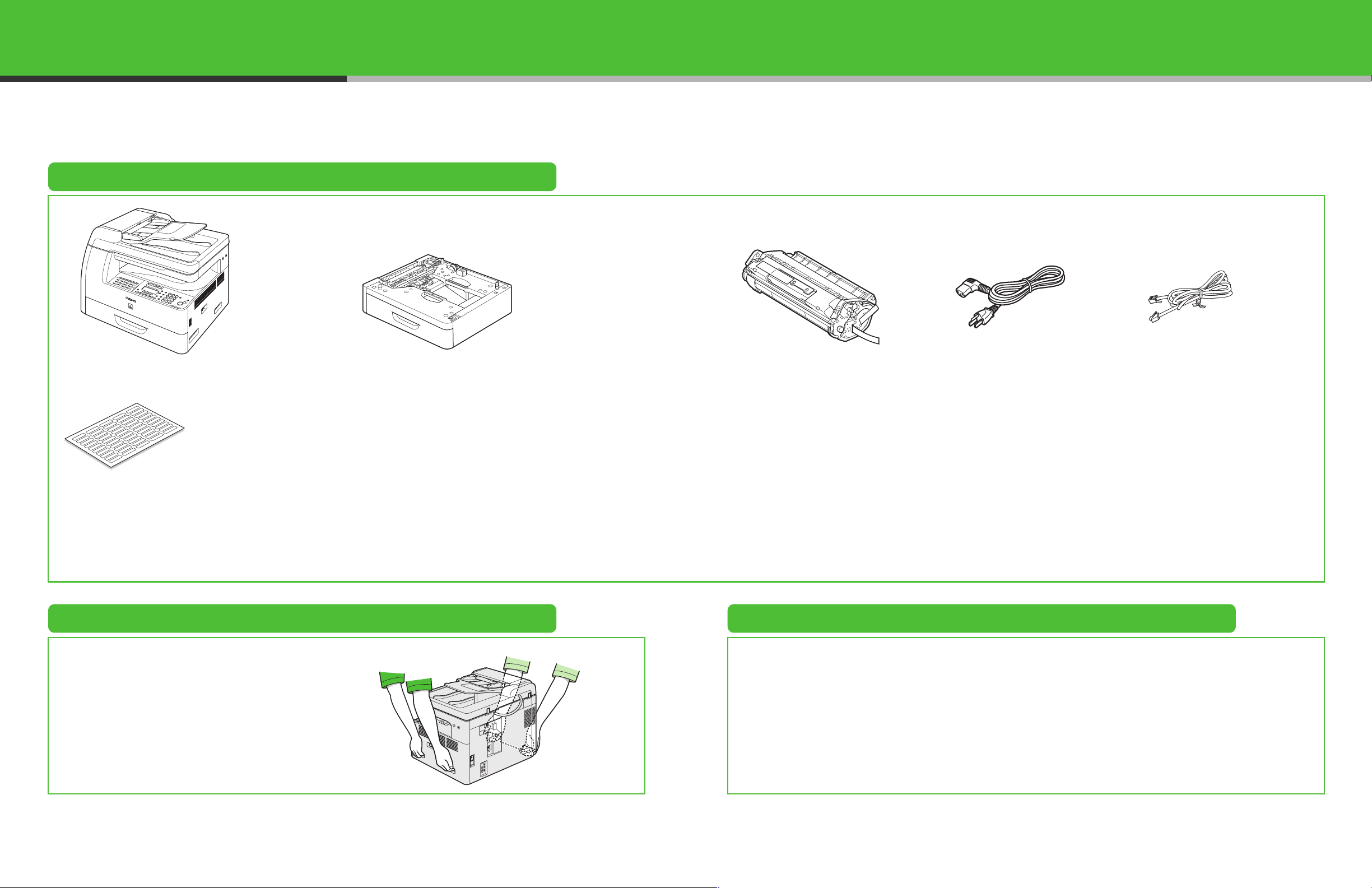
Do You Have Everything?
●Machine ●Paper Cassette (optional)** ●Toner Cartridge ●Power Cord ●Telephone Cable*
●Destination Labels*
●Starter Guide
●Basic Guide
●User Software CD
* MF6550/ MF6560/ MF6580 Only
**MF6560/ MF6580 Only
●Limited Warranty Notice
●Registration Card
●Unpacking Instructions
Before Setting Up the Machine Manuals for the Machine
● Remove all shipping tape on the machine.
● When moving the machine, be sure at least two
people carry it using the provided hand grips on
the left and right sides, as seen in the illustration
right.
● The machine illustration may differ slightly from
your machine.
● Starter Guide (This Document): Machine set-up and software installation
● Basic Guide: Basic features, maintenance, machine settings, and specifications
● Advanced Guide (in User Software CD): Advanced features, network and remote user interface,
system monitor, and reports and lists
● Scanner Driver Guide (in User Software CD): Scanner settings from a computer
1 2
Page 3
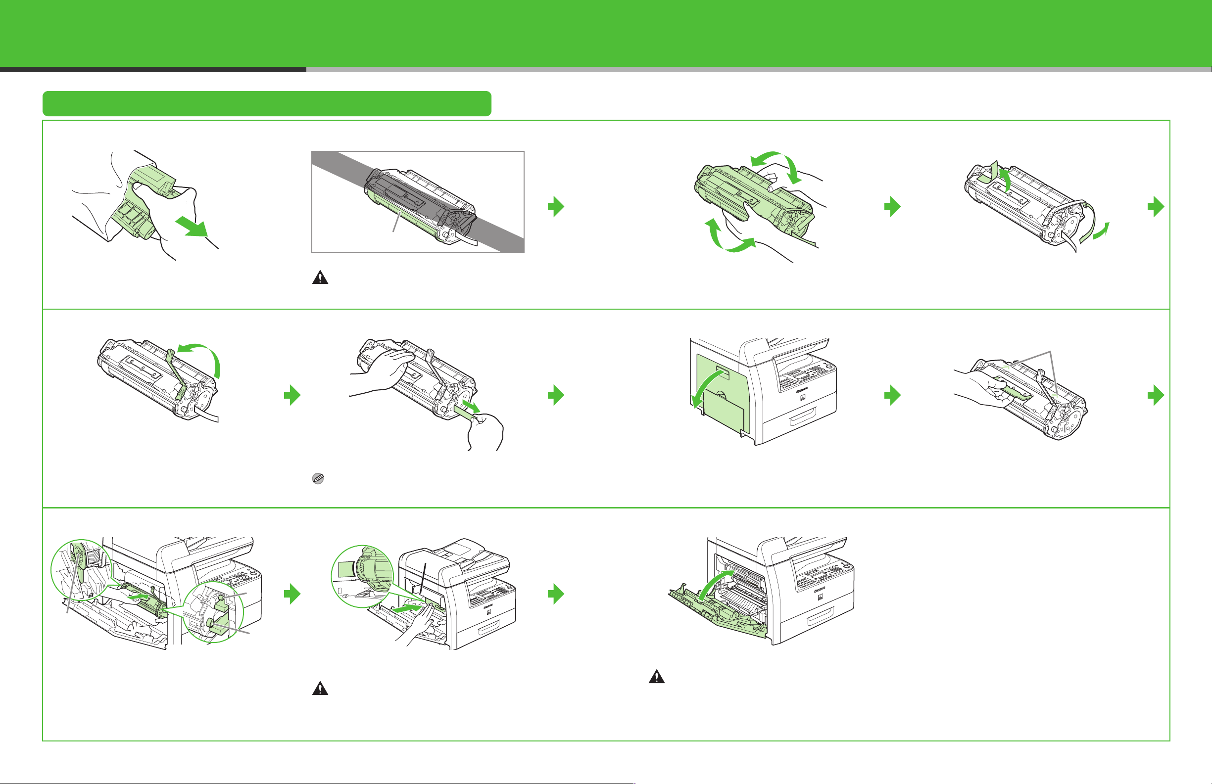
Install Toner Cartridge
1
Remove the toner cartridge from the bag.
Keep the bag for future use.
4
A
CAUTION
Do not open the drum protective shutter (A).
5
2
Gently rock the toner cartridge 5 or 6 times to
distribute toner evenly.
6
3
Remove the seals (2 places).
7
A
Raise the blue plastic pull tab as in the illustration
above.
8
B
A
C
The left edge (A) and the right side protrusions (B,
C) of the toner cartridge should be aligned with the
guides inside the machine. The Blue plastic pull tab
should be pulled up as illustrated in step 4.
Pull out the seal completely.
NOTE
Do not pull out the seal at an angle.
9
A
Push the toner cartridge to make sure it is properly
set in the machine.
CAUTION
Do not touch the fixing assembly (A) as it becomes very
hot during use.
Open the left cover.
10
Close the left cover.
CAUTION
– Be careful not to get your fingers caught.
– If you cannot close the left cover, do not force it to
close. Open the cover and make sure the toner
cartridge is properly set in the machine.
Hold the toner cartridge by its handle. Insert the
toner cartridge into the machine with the arrows (A)
on the toner cartridge pointing toward the machine.
3
4
Page 4
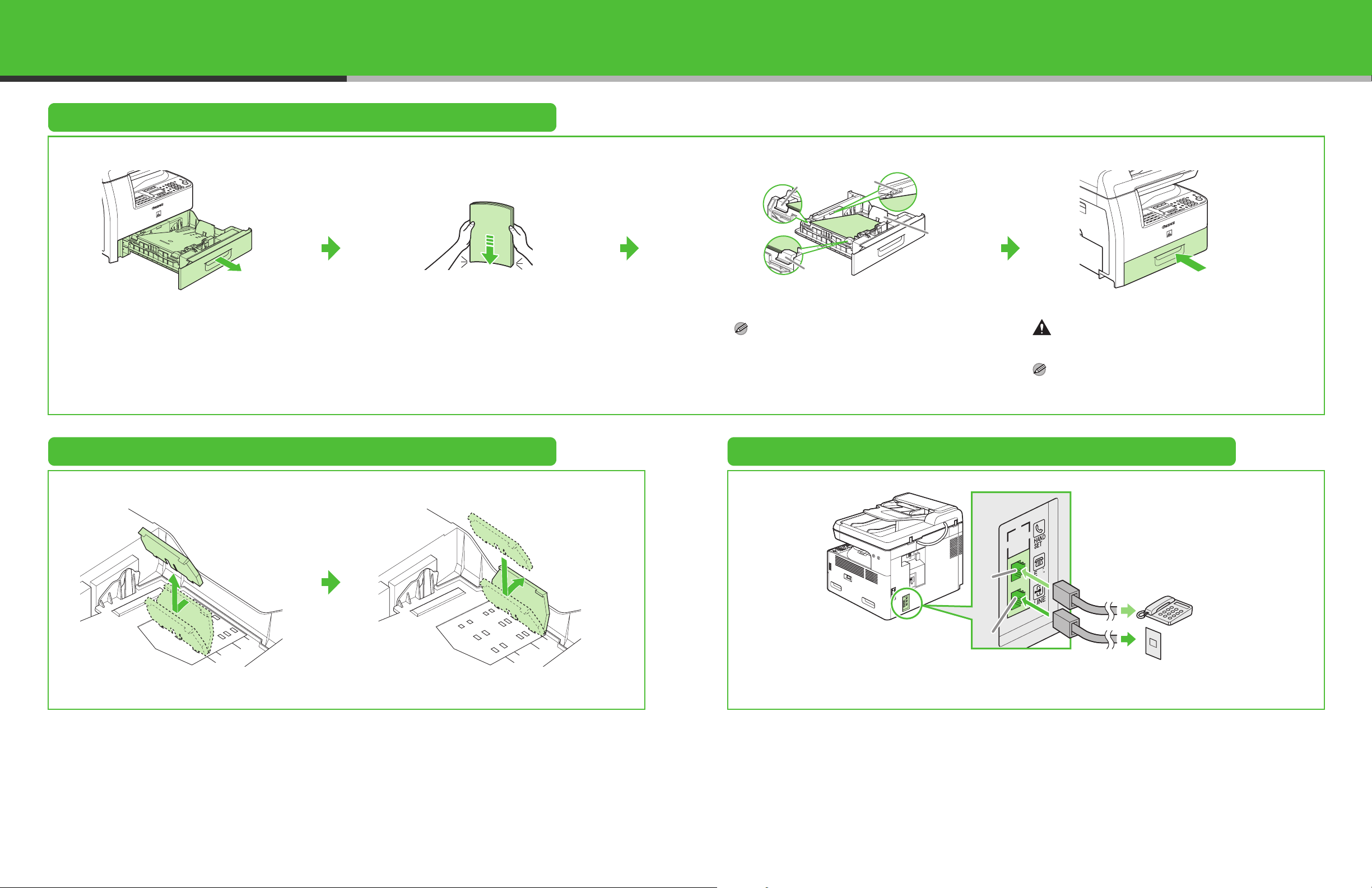
Load Paper
1
Pull out the paper cassette until it stops.
2
Even the edges of the paper stack.
Set Up the Paper Cassette to Fit the Paper Size
3
B
B
Load the paper stack print side up.
NOTE
Make sure the back edge of the paper stack touches the
rear paper end guide (C), the paper stack should not
exceed the load limit mark (A), and the load is under the
hooks (B) on the paper guides.
Connect Telephone Cables
A
C
4
Gently insert the paper cassette as far as it will go.
CAUTION
Be careful not to get your fingers caught.
NOTE
For loading paper in the multi-purpose tray, see
Chapter 3, “Print Media,” in the Basic Guide.
(MF6550/MF6560/MF6580 Only)
1
Incline the rear paper end guide until it is unlocked,
then remove it from the paper cassette.
2
Attach the guide to the slots of the desired paper
size.
B
A
Connect the supplied telephone cable to the line jack (A) and the wall jack.
Connect your external telephone to the external device jack (B) if required.
5
6
Page 5
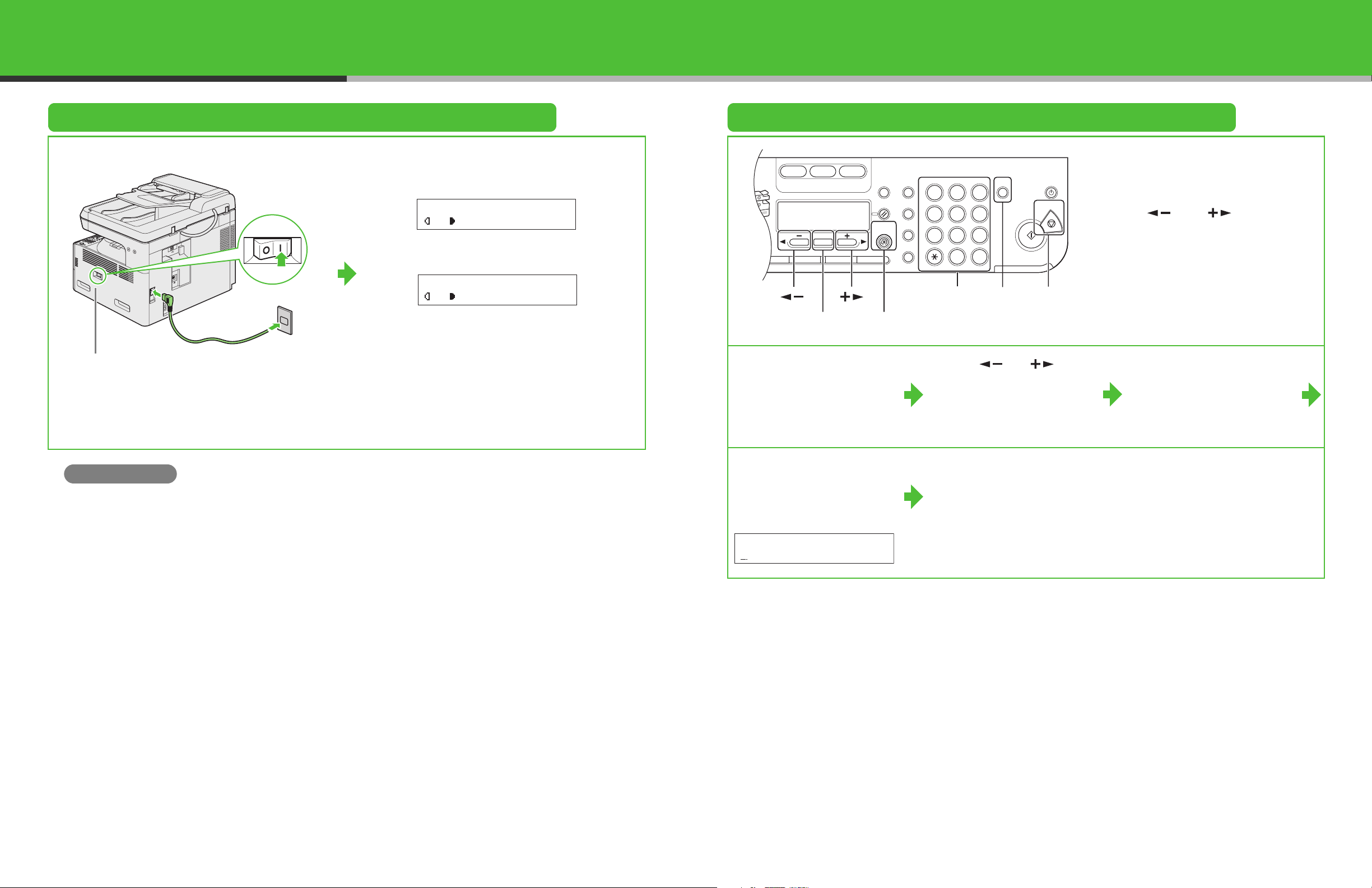
Connect Power Cord and Turn On the Machine
Paper
Select
COPY FAX SCAN
Image Quality Density Enlarge/ReduceOKTwo-Sided
System
Monitor
View
Settings
Reset Collate
GHI
@./
PQRS
Tone
JKL
ABC
TUV
MNO
DEF
Clear ON/OFF
Stop
Start
Processing/
Data
Error
Power
WXYZ
SYMBOLS
Additional
Functions
2 on 1
Frame
Erase
1
4
7
2
5
8
0#
3
C
6
9
Set the Date and Time
12
Without optional cassette
Main power switch
Connect the power cord into the rear socket and the wall
outlet and press the [I] side of the main power switch to ON.
What if...
● <CLOSE COVER LEFT COVER> is displayed:
Make sure that the left cover is closed properly.
(See “Install Toner Cartridge,” on p. 3.)
● <TONER IS NOT SET INSTALL TONER> is displayed:
Make sure that the toner cartridge is installed properly.
(See “Install Toner Cartridge,” on p. 3.)
100% LTR
A
TEXT
With optional cassette
100% AUTO
A
TEXT
The machine enters standby mode.
01
01
[OK]
[Additional Functions]
1 Press [Additional
Functions].
4 Use the numeric keys to
enter the date (month/day/
year) and time (in 24-hour
format), then press [OK].
Ex.
DATE&TIME SETTING
12/31/´06 11:19
[Clear]
[Stop]Numeric Keys[][]
2 Use [ ] or [ ] to
select <6. TIMER
SETTINGS>, then press
[OK].
5 Press [Stop] to return to
standby mode.
● Entering Information
– Numeric keys: Enter letters and
numbers.
– [ ] and [ ]: Move the
cursor position.
– [Clear]: Deletes the character at
the cursor position, or the entire
entry if held for more than one
second.
3
Confirm that
<1. DATE&TIME
SETTING> is displayed,
then press [OK].
7
8
Page 6

Set the Machine for Sending Faxes
Paper
Select
COPY FAX SCAN
Image Quality Density Enlarge/ReduceOKTwo-Sided
System
Monitor
View
Settings
Reset Collate
GHI
@./
PQRS
Tone
JKL
ABC
TUV
MNO
DEF
Clear
Sta
Processing/
Data
Error
P
WXYZ
SYMBOLS
Additional
Functions
2 on 1
Frame
Erase
1
4
7
2
5
8
0#
3
C
6
9
(MF6550/MF6560/MF6580 Only)
Guidelines for Entering Information
The sender information you register in the machine appears in the header of each page received by your
recipient.
Fax/telephone
Date and time
12/31/2006 10:50 FAX 123XXXXXXX CANON
NOTE
Before sending a fax, you MUST register your fax number, user name, and the current date and time in the machine.
number
Unit name Page number
001
Entering Information
Use the following keys to enter information in the machine.
● Use the numeric keys to enter characters. Press
the numeric key repeatedly until the required
character appears.
● Press [#] to enter symbols.
● Press [ ] to switch among input modes:
– [:A]: Letter (uppercase) mode
– [:a]: Letter (lowercase) mode
– [:1]: Number mode
● Press [ ] or [ ] to move the cursor.
[OK]
[][]
[] [#]
Numeric Keys
[Clear]
● Press [Clear] to delete the character at the
cursor position. Hold [Clear] to delete the entire
entry.
● Press [OK] to confirm the entry.
You can enter the following characters in each input mode:
:A :a
[1] @.-_/ @.-_/
[2] ABC abc 2
[3] DEF def 3
[4] GHI ghi 4
[5] JKL jkl 5
[6] MNO mno 6
[7]
[8]
[9]
PQRS pqrs
TUV tuv
WXYZ wxyz
[0] 0
[ ]
[#]
:A
– . # ! " , ; : ^ _ = / | ’ ? $ @ % & + \ ( ) [ ] { } < >
:a
7
8
9
:1
:1
1
9
10
Page 7

Register Sender Information
Paper
Select
COPY FAX SCAN
Image Quality Density Enlarge/ReduceOKTwo-Sided
System
Monitor
View
Settings
Reset Collate
GHI
@./
PQRS
Tone
JKL
ABC
TUV
MNO
DEF
Clear ON/OFF
Stop
Start
Processing/
Data
Error
Power
WXYZ
SYMBOLS
Additional
Functions
2 on 1
Frame
Erase
1
4
7
2
5
8
0#
3
C
6
9
[]
[]
[OK]
[Additional Functions]
4 Confirm that <1. UNIT
TELEPHONE #>
displayed
, then press
[OK].
is
[] []
Numeric Keys
[Clear]
5 Use the numeric keys to
enter your fax/telephone
number (max. 20 digits,
including spaces), then
press [OK].
UNIT TELEPHON#
[Stop]
● Entering Information
– Numeric keys: Enter letters and
numbers.
– [ ]: Enter symbols.
– [ ]: Switches letter and number
input modes.
– [ ] and [ ]: Move the
cursor position.
– [Clear]: Deletes the character at
the cursor position, or the entire
entry if held for more than one
second.
6 Confirm that <2. UNIT
NAME> is displayed, then
press [OK].
1 Press [Additional
Functions].
7 Use the numeric keys to
enter the unit name (up to
24 characters), then press
[OK].
Ex.
UNIT NAME :A
2 Use [ ] or [ ] to
select <3. FAX
SETTINGS>, then press
[OK].
8 Press [Stop] to return to
standby mode.
3
Use [ ] or [ ] to
select <2. USER
SETTINGS>, then press
[OK].
Set the Telephone Line Type
1 Press [Additional
Functions].
11
2 Use [ ] or [ ] to
select <3. FAX
SETTINGS>, then press
[OK].
3 Use [ ] or [ ] to
select <2. USER
SETTINGS>, then press
[OK].
4 Use [ ] or [ ] to
select <5. TEL LINE
TYPE>, then press [OK].
5 Use [ ] or [ ] to
select the telephone line
type, then press [OK].
<TOUCH TONE>: Tone dialing
(default)
<ROTARY PULSE>: Pulse dialing
6 Press [Stop] to return to
standby mode.
12
Page 8

Set the Machine for Receiving Faxes
(MF6550/MF6560/MF6580 Only)
Select the Receive Mode that Suits Your Needs
Follow the chart below to determine the correct receive mode for your needs.
Do you intend to use the machine to
receive voice calls?
Yes
Do you intend to use an answering
machine with the machine?
No
Do you intend to receive faxes
automatically?
Yes
Do you subscribe to a DRPD service?
Yes
No
Yes <AnsMode>
No
No
<FaxOnly>
Answers all calls as faxes.
Receives faxes automatically
and records voice messages.
<Manual>
Does not answer any calls.
You have to manually receive
faxes.
<FaxTel>
Switches between fax and
voice calls automatically if a
telephone is connected to the
machine.
Set the Receive Mode
1 Press [Additional
Functions].
4 Use [ ] or [ ] to
select the receive mode,
then press [OK].
2 Use [ ] or [ ] to
select <3. FAX
SETTINGS>, then press
[OK].
5 Press [Stop] to return to
standby mode.
3 Confirm that
<1. RX MODE> is
displayed, then press
[OK].
NOTE
For details, see the Advanced
Guide (in User Software CD).
<DRPD>
Distinguishes between fax and
voice calls, if you want to use
an external phone.
NOTE
– The answering machine must be connected directly to the machine for <AnsMode> to work.
– An external telephone must be connected to the machine for <FaxTel>, <Manual> or <DRPD> to work.
– Voice mail is not supported with <AnsMode>.
– The <DRPD> mode requires subscription to a DRPD (Distinctive Ring Pattern Detection) service. Contact your telephone
company for availability.
13
14
Page 9

Installing/Uninstalling Software
Installation Procedure
Before Installation:
• Do not connect the USB cable before installing the
software. If you connect the USB cable before
installing the software and the Found New Hardware
Wizard screen appears, click [Cancel].
• For Windows 2000/XP/Server 2003, logon as
Administrator to install the software.
• Make sure the machine is turned on before connecting
the USB cable.
• On the screen shown at each step, click on the circled
button to proceed.
34
If the MF6500 Series CD-ROM
Setup screen is not displayed,
on the Windows desktop
double-click [My Computer].
Open the CD-ROM icon, then
double-click [MInst (MInst.exe)].
System Requirements
Microsoft Windows 98/98SE
CPU: Intel Pentium/66 MHz or faster
Memory: 128 MB or more
Available Hard Disk Space: 460 MB or more
Microsoft Windows Me
CPU: Intel Pentium/150 MHz or faster
Memory: 128 MB or more
Available Hard Disk Space: 460 MB or more
Microsoft Windows 2000
CPU: Intel Pentium/133 MHz or faster
Memory: 128 MB or more
Available Hard Disk Space: 460 MB or more
Microsoft Windows XP (32-bit version)
CPU: Intel Pentium/Celeron series
233 MHz or faster
Memory: 128 MB or more
Available Hard Disk Space: 460 MB or
more
Microsoft Windows Server 2003
(32-bit version)*
CPU: Intel Pentium/Celeron series
133 MHz or faster
Memory: 128 MB or more
Available Hard Disk Space: 460 MB or
more
* Only for network connection.
NOTE
Installation of PageManager and
OmniPage is required only for the
MF6530/6531/6550.
(PageManager and OmniPage
are not supplied with the
MF6560/6580.)
For USB Connection
12
56
7 8 9 101112
15
16
Page 10

When you install PageManager
E
E
and OmniPage, follow the onscreen instructions.
13 14 15
Connect the machine and your
computer with a USB cable (A).
16
A
You have now completed
installation.
For Network Connection (MF6580 Only)
NOTE
– This machine is set by default to
automatically draw an IP address
using DHCP. If your network server
or router is configured to provide a
DHCP address, all you need to do
is connect a network cable and
turn on the machine. The machine
will draw an IP address
automatically.
5 Confirm that <1. IP
ADDRESS AUTO.> is
displayed, then press
[OK].
– This machine also supports
automatic IP addresses using
BOOTP and RARP protocols. For
definitions and an explanation of
each, please refer to the Advanced
Guide.
6 Use [ ] or [ ] to
select <OFF>, then press
[OK].
Specify the IP Address
Manually
1 Press [Additional
Functions].
7 Confirm that <2. IP
ADDRESS> is displayed,
then press [OK].
2 Use [ ] or [ ] to
select <9. SYSTEM
SETTINGS>, then press
[OK].
8 Use the numeric keys to
enter the IP address
number, then press [OK].
x.
IP ADDRESS
000.000.000.000
3 Use [ ] or [ ] to
select <2. NETWORK
SETTINGS>, then press
[OK].
9 Confirm that <3. SUBNET
MASK> is displayed, then
press [OK].
4 Confirm that <1. TCP/IP
SETTINGS> is displayed,
then press [OK].
10 Use the numeric keys
to enter the subnet
mask number, then
press [OK].
x.
SUBNET MASK
000.000.000.000
17
18
Page 11

11 Confirm that <4.
E
GATEWAY
ADDRESS> is
displayed, then press
[OK].
Install Software
12 Use the numeric keys
to enter the gateway
address number, then
press [OK].
l
x.
GATEWAY ADDRESS
000.000.000.000
13 Press [Stop] to return
to standby mode.
14 Restart the machine. 15
A
Connect the machine and your
network router or a hub with a
category 5 rated (Cat 5) twistedpair LAN cable (A).
12
If the MF6500 Series CD-ROM
Setup screen is not displayed,
on the Windows desktop
double-click [My Computer].
Open the CD-ROM icon, then
double-click [MInst (MInst.exe)].
3
4
While installing the software on
a computer running Windows
Server 2003, the display in this
step does not appear.
567 8910
Repeat this step for each driver
that you have selected.
19 20
Page 12

11 12 13 14
15 16 17
You have now completed
installation.
21 2221
Page 13

Uninstallation Procedure
Before you remove the
driver, make sure of the
following:
● You have the installation
software available for
installation.
● No application is running
on your computer.
NOTE
– To uninstall the software in
Windows 2000/XP/Server
2003, you must be the user with
administrative privileges.
– When removing the software,
first remove the MF Toolbox,
and then the MF drivers.
3 Click [Yes].
Uninstallation proceeds
automatically and next dialog box
appears.
Removing the MF Toolbox Removing the MF Drivers
1 Click [start] on the
Windows task bar → [(All)
Programs] → [Canon] →
[MF Toolbox 4.9] →
[Toolbox Uninstall].
2 Follow the on-screen
instructions.
When the Repair or Remove
program selection screen is
displayed, check [Remove], then
click [Next >].
If asked to confirm removal of an
application etc., click [OK].
Restart your computer if asked to
do so.
3 Click [Exit]. 1 Click [start] on the
Windows task bar → [(All)
Programs] → [Canon] →
[MF6500 Series] →
[Uninstall Drivers].
The [MF Drivers Uninstaller] dialog
box appears.
4 Click [Exit].
Bundled on the User Software CD
When you install the following programs, click on the [Additional Software Programs] button in step 2 of
“Installation Procedure – For USB Connection” or in step 2 of “Installation Procedure – For Network
Connection – Install Software,” then follow the instructions that appear on the screen.
● Canon Cover Sheet Editor
The Canon Cover Sheet Editor enables you to create original fax cover sheet templates for use with Canon
NOTE
Restart your computer if asked to
do so.
fax driver. For details, see the online help for this program.
● NetSpot Device Installer (NSDI)
NetSpot Device Installer enables you to set up the machine for network operations.
For details, see the Readme file and online help for this program.
2 Click [Delete].
23
24
Page 14

Using Help
The user software CD includes programs (driver software and application software) which the
supplied instruction guides do not cover. When you utilize such programs, refer to online help
and context sensitive help following the instructions below.
Online Help
You can locate additional help in the online help file
provided with the driver software. In the
[Properties] dialog box, you can click [Help] to
display information about every feature and option
in the drivers.
In the help dialog box, you can click
[Contents], then double-click your desired
title to display information.
Context Sensitive Help
Context sensitive help displays an
explanation of each item in the current dialog
box. Use one of the following methods to
show context sensitive help.
– Click (Help) in the title bar of the dialog
box → click the desired item.
– Right-click the desired item → select
[What's this?]
– Select the desired item → press [F1]
Contacting Service Center
If you have a problem with your machine and you cannot solve it by referring to the manuals, please
contact our Canon Authorized Service Facilities or the Canon Customer Care Center at 1-800-8284040 between the hours of 8:00 A.M. to 8:00 P.M. EST Monday through Friday and 10:00 A.M. to
8:00 P.M. on Saturday.
In the help dialog box, you can click [Index],
then double-click your desired keyword in the
list to display information. To search the
desired keyword quickly, enter a keyword in
the upper text box. The nearest keyword is
located in the list below.
Canon, the Canon logo, imageCLASS, and NetSpot are trademarks of Canon Inc.
Microsoft and Windows are registered trademarks of Microsoft Corporation.
All other product and brand names are registered trademarks, trademarks or service marks of their
respective owners.
Specifications subject to change without notice.
25
26
Page 15

A Tip for Saving Paper
DEF
DEF
DEF
DEF
ABC
ABC
ABC
ABC
1
DEF
DEF
DEF
DEF
ABC
ABC
ABC
ABC
1
DEF
DEF
DEF
DEF
The machine comes with useful features that can be combined to reduce the volume of paper used
when copying.
Copying regularly
Copying with features combined
■ Collate Copying
(See the Advanced Guide.)
AAAA
AAAA
BBBB
AAAA
BBBB
CCCC
AAAA
BBBB
CCCC
DDDD
1
BBBB
CCCC
DDDD
CCCC
DDDD
DDDD
2
3
4
AAAA
AAAA
AAAA
AAAA
■ Two-Sided Copying
(See the Advanced Guide.)
ABC
ABC
ABC
ABC
1
2
■ 2 on 1 Combination
(See the Advanced Guide.)
ABC
ABC
ABC
ABC
1
2
AAAA
AAAA
AAAA
AAAA
AAAA
1
AAAA
AAAA
1
AAAA
ABC
ABC
ABC
ABC
1
AAAA
AAAA
AAAA
1
AAAA
1
2
Combinations of Features
e
To get the best use of the machine’s
copy features, try other combinations
listed in this table.
●: Available
2
2 on 1 Combination ––●●●●●
Original Frame Erase –––●●●●
Book Frame Erase –– –●●●●
Binding Hole Erase ● –– ●●●●
1 to 2-Sided ●●●● ––●
2 to 2-Sided ●●●● ––●
2 to 1-Sided ●●●● –– ●
on
i
t
na
i
b
m
o
C
1
n
i
o
r
O
s
a
r
s
E
a
r
e
E
m
e
a
r
m
F
a
l
a
Fr
n
k
gi
o
i
o
B
B
e
e
s
a
r
E
e
l
d
o
H
d
g
n
di
n
i
S
-
2
o
t
1
e
e
d
i
S
-
2
o
t
2
d
d
e
d
i
S
e
-
1
o
t
2
t
a
l
l
o
C
Collate ●●●●●●●
Page 16

CANON INC.
30-2, Shimomaruko 3-chome, Ohta-ku, Tokyo 146-8501, Japan
CANON U.S.A., INC.
One Canon Plaza, Lake Success, NY 11042, U.S.A.
CANON CANADA INC.
6390 Dixie Road Mississauga, Ontario L5T 1P7, Canada
CANON EUROPA N.V.
Bovenkerkerweg 59-61 1185 XB Amstelveen, The Netherlands
CANON FRANCE S.A.S.
17, quai du Président Paul Doumer 92414 Courbevoie Cedex, France
CANON COMMUNICATION & IMAGE FRANCE S.A.S.
12, rue de I’Industrie 92414 Courbevoie Cedex, France
CANON (U.K.) LTD.
Woodhatch, Reigate, Surrey, RH2 8BF, United Kingdom
CANON DEUTSCHLAND GmbH
Europark Fichtenhain A10, 47807 Krefeld, Germany
CANON ITALIA S.p.A.
Via Milano, 8 20097 San Donato Milanese (MI) Italy
CANON ESPAÑA, S.A.
c/ Joaquín Costa 41, 28002 Madrid, Spain
CANON LATIN AMERICA, INC.
703 Waterford Way Suite 400, Miami, Florida 33126 U.S.A.
CANON AUSTRALIA PTY. LTD
1 Thomas Holt Drive, North Ryde, Sydney, N.S.W. 2113, Australia
CANON CHINA CO.,LTD
15F, North Tower, Beijing Kerry Centre, 1 Guang Hua Road, Chao Yang District, 100020, Beijing, China
CANON SINGAPORE PTE. LTD.
1 HarbourFront Avenue #04-01 Keppel Bay Tower, Singapore 098632
FA7-8173 (010) © CANON INC. 2006 PRINTED IN JAPAN OR CHINA
 Loading...