

Canon BJC-6010 Series User Manual

BJC-6000
BJC-6010
SERVICE
MANUAL
Canon

Target Readers
This manual is published by Canon Inc. for qualified persons and contains the necessary technical
information for technical theory, installation, maintenance, and repair of products. This manual
covers all localities where the products are sold. For this reason, It may contain information that does
not apply to your locality.
Revisions
This manual may include technical inaccuracies or typographical errors due to improvements or
changes in the products. When amendments are made to the content of this manual, Canon will issue
technical information as the need arises. In the event of major alterations to the content of this manual
over a long or short period, Canon will publish a revised version of the manual.
The following paragraph does not apply to any countries where such provisions are
inconsistent with local law.
Trademarks
The product names and company names appearing in this manual are the registered trademarks or
trademarks of the individual companies.
Copyright
This manual is copyrighted and all rights reserved. Under the copyright laws, this manual may not
be copied, reproduced, or translated into other language, in whole or in part, without the express
written consent of Canon Inc. except in the case of internal business use.
Copyright 1999 by Canon Inc.
CANON INC.
BJ Products Quality Support Dept.
16-1, Shimonoge 3-chome, Takatsu-ku, Kawasaki-shi, Kanagawa 213, Japan
This manual was produced on an Apple Macintosh Power Mac 9600/233 personal computer and
Apple LaserWriter II NTX-J laser beam printer; final pages were printed on Varityper 5300 with
4000-J RIP. A Canon mo-5001S Magneto-Optical Storage Subsystem with mo-502M Magneto-Optical
Storage Disk Cartridge and mo-IF2 interface kit were used for storing large volumes of page layout and
graphic data for this manual.
All graphics were produced with MACROMEDIA FREEHAND 7.0J.
All documents and all page layouts were created with QuarkXPress 3.3J.
I. ABOUT THIS MANUAL
This manual is divided into five parts containing the information required for servicing
the BJC-6000 printer.
Part 1: Safety and Precautions
This part contains information on how to service the unit safety. It is very
important, and must be read.
Part 2: Product Specifications
This part outlines the product and its specifications.
Part 3: Operating Instructions
This part explains how to operate the unit properly, how it is installed, and how to
use the service mode.
Part 4: T echnical Reference
This part outlines the unit operation giving a technically.
Part 5: Maintenance
This part explains maintenance of the unit. It includes details of disassembly /
assembly, adjustments required when assembling troublishooting procedures, and
wiring / circuit diagrams, etc.
This manual does not contain complete information required for
disassembling and assembling the BJC-6000 printer. Please also refer to
the separate Parts Catalog.
REF.
I

II. TABLE OF CONTENTS
Page
Part 1: SAFETY AND PRECAUTIONS
1 - 1 1. SAFETY PRECAUTIONS
1 - 1 1.1 Moving Parts
1 - 2 1.2 Ink Stains
1 - 2 1.2.1 Ink pat hs
1 - 2 1.2.2 Ink mist
1 - 4 1.3 Live Electrical Parts
1 - 5 2. MACHINE PRECAUTIONS
1 - 5 2.1 BJ Cartridges
1 - 5 2.1.1 BJ cartridge handling
1 - 6 2.1.2 Automatic capping
1 - 6 2.1.3 When not using the printer
1 - 6 2.1.4 Ink's electroconductivity
1 - 7 2.2 Ink Tanks
1 - 7 2.2.1 Unpacking the ink tank
1 - 7 2.2.2 Ink tank handling
1 - 8 2.3 Printer Handling
1 - 8 2.3.1 Spurs
1 - 9 2.3.2 Damage due to static electricity
1 -10 2.3.3 Ink leakage prevention
1 -11 3. NOTES ON SERVICING
1 -11 3.1 EEPROM Data
1 -12 3.2 Static Electricity
1 -13 3.3 Disassembly and Reassembly
1 -14 3.4 Self Diagnosis
Part 2: PRODUCT SPECIFICATIONS
2 - 1 1. PRODUCT OUTLINE
2 - 1 1.1 Outline
2 - 2 1.2 Features
2 - 3 1.3 BJ Cartridge
2 - 3 1.3.1 Black BJ cartridge
2 - 3 1.3.2 Color BJ cartridge
2 - 4 1.3.3 Photo BJ cartridge
2 - 4 1.4 BJ Cartridge Container
2 - 5 1.5 Consumables
2 - 5 1.5.1 Black, color, and photo BJ cartridges
2 - 5 1.5.2 Ink tanks
2 - 6 2. SPECIFICATIONS
2 - 6 2.1 General Specifications
2 - 8 2.2 Paper Specifications
2 -10 2.3 Interface Specifications
Part 3: OPERATING INSTRUCTIONS
3 - 1 1. PRINTER SETUP
3 - 1 1.1 Unpacking
3 - 2 1.2 Installation Location
3 - 3 1.3 Installation
3 - 3 1.3.1 Connecting the interface cable
3 - 3 1.3.2 Connecting the power cord
3 - 3 1.3.3 Installing the BJ cartridges
II

Page
3 - 9 1.3.4 Aligning the print heads
3 -10 1.4 Names of Parts and Their Functions
3 -11 2. TRANSPORTING THE PRINTER
3 -11 2.1 Transporting the Printer
3 -12 3. PRINTER SERVICE FUNCTIONS
3 -12 3.1 Error Indications
3 -13 3.2 Description of Error Indications
3 -14 3.3 BJ Status Monitor
3 -14 3.3.1 Main functions of the BJ status monitor
3 -14 3.3.2 Items displayed on the BJ status monitor
3 -15 3.4 Function Settings
3 -15 3.4.1 Function settings using the printer driver
3 -16 3 .5 Off-Line Operations
3 -16 3.5.1 Cleaning
3 -16 3.5.2 Nozzle check pattern printing
3 -17 3.5.3 Roller cleaning
3 -18 3 .6 Service Mode
3 -18 3.6.1 Service mode operations
3 -19 3.6.2 Service/factory test print
3 -20 3.6.3 EEPROM information print
3 -21 3.6.4 Resetting EEPROM
3 -21 3.6.5 Model setting
3 -21 3.6.6 Automatic head position adjustment
Part 4: TECHNICAL REFERENCE
4 - 1 1. OVERVIEW
4 - 1 1.1 Printer Block Diagram
4 - 2 1. 2 Power On Sequence Flowchart
4 - 3 1.3 Flow of Print Signals
4 - 4 1.4 Print Driving
4 - 2 1.4.1 Print drive control
4 - 6 1.4.2 Print drive method
4 - 9 1.5 Power-Off Sequence Flowchart
4 -10 2. FIRMWARE
4 -10 2.1 Interface
4 -10 2.1.1 Compatible mode
4 -11 2.1.2 Nibble mode
4 -12 2.1.3 ECP mode
4 -13 2.2 Print Control
4 -13 2.2.1 Print mode
4 -13 2.2.2 Multi-drop print
4 -13 2.2.3 Photo-print
4 -13 2.2.4 Automatic switching control of printing nozzles
4 -15 2.3 Automatic Printing Position Alignment Function
4 -16 2.4 Pause Between Scanning
4 -16 2.5 Pause Between Pages
4 -16 2.6 Smear Control
4 -16 2.7 Auto Power ON/OFF
4 -16 2.8 Head Overheat Protection
4 -17 3. PRINTER'S MECHANICAL SYSTEM
4 -17 3.1 Overview
4 -17 3.1.1 BJ cartridge unit
4 -17 3.1.2 Carriage unit
III

Page
4 -18 3.1.3 Purge unit
4 -18 3.1.4 Paper feed unit
4 -19 3.2 BJ Cartridge
4 -19 3.2.1 Construction of the Black BJ cartridge
4 -20 3.2.2 Construction of the Color/Photo BJ cartridge
4 -21 3.2.3 Construction of the bubble jet head unit
4 -25 3 .3 Purge Unit
4 -25 3.3.1 Function of the purge unit
4 -26 3.3.2 Construction of the purge unit
4 -28 3.4 Paper Feed Unit
4 -28 3.4.1 Functions of the paper feed unit
4 -30 3.4.2 Construction of the paper feed unit
4 -32 3.5 Carriage Unit
4 -32 3.5.1 Functions of carriage unit
4 -33 3.5.2 Construction of the carriage unit
4 -36 4 PRINTER'S ELECTRICAL SYSTEM
4 -36 4.1 Overview
4 -37 4. 2 Control Unit
4 -37 4.2.1 Control unit block diagram
4 -38 4.2.2 Logic Components
4 -41 4.3 Power Supply Unit
4 -41 4.3.1 Power Supply Unit Block Diagram
4 -41 4.3.2 Construction of Power Supply Unit
4 -42 5. DETECTION FUNCTIONS
4 -42 5 .1 Detection with Sensors
4 -42 5.1.1 Home position sensor
4 -42 5.1.2 Paper end sensor
4 -42 5.1.3 Print position sensor
4 -43 5.1.4 Ink sensor
4 -43 5.1.5 Cover sensor
4 -43 5.1.6 Pump sensor
4 -43 5.1.7 Printer temperature sensor (TH201)
4 -44 5.1.8 Head temperature sensor
4 -44 5.2 Other Detection Functions
4 -44 5.2.1 Waste ink amount detection
4 -44 5.2.2 BJ cartridge detection
Part 5: MAINTENANCE
5 - 1 1. MAINTENANCE
5 - 1 1.1 Parts for Periodic Replacement
5 - 1 1.2 List of Consumables
5 - 1 1.3 List of Periodic Maintenance
5 - 2 2. SERVICE TOOLS
5 - 2 2.1 List of Tools
5 - 3 3. APPLYING GREASE
5 - 4 4. DISASSEMBLY AND REASSEMBLY
5 - 4 4.1 Disassembly and Reassembly
5 - 4 4.2 Notes on Disassembly and Reassembly
5 - 4 4.2.1 Unlocking the carriage
5 - 5 4.2.2 Removing the printer unit
5 - 6 4.2.3 Removing the ASF unit
5 - 6 4.2.4 Removing the adjustable bearings supporting the carriage shaft
5 - 7 4.2.5 Paper feed gears
5 - 8 5. ADJUSTMENTS AND SETTINGS
5 - 8 5.1 Adjustments and Settings
IV

5 - 8 5.1.1 EEPROM setting
5 - 8 5.1.2 Carriage belt tension adjustment
5 - 8 5.1.3 ASF gear position adjustment
5 - 8 5.1.4 Head gap adjustment
5 - 9 5 .2 Adjustment/Setting Procedures
5 - 9 5.2.1 EEPROM setting
5 - 9 5.2.2 Carriage belt tension adjustment
5 -10 5.2.3 ASF gear position adjustment
5 -11 5.2.4 Head gap adjustment
5 -13 6. TROUBLESHOOTING
5 -13 6.1 Troubleshooting Overview
5 -13 6.1.1 Overview
5 -13 6.1.2 Notes on troubleshooting
5 -15 6.2 Diagnosis
5 -15 6.2.1 Initial flowchart
5 -18 6.2.2 Action
5 -36 7. CONNECTOR POSITIONS AND PIN ASS
5 -36 7.1 Control Board
5 -40 7.2 Carriage Board
5 -43 7.3 BJ Cartridge
5 -44 7.4 AC adapter
5 -44 7.5 DC power supply cable
5 -45 7.6 Carriage Motor
5 -45 7.7 Paper Feed Motor
5 -46 7.8 Ink Sensor
5 -46 7 .9 Print Position Sensor
5 -46 7. 10Pump Sensor
5 -47 8. CIRCUIT DIAGRAMS
5 -47 8.1 Parts Layout
5 -47 8.1.1 Control board
5 -48 8.1.2 Carriage board
5 -49 8.2 Circuit Diagrams
V

III. ILLUSTRATION INDEX
Page
Part 1: SAFETY AND PRECAUTIONS
1 - 1 Figure 1- 1 The Printer's Moving Parts
1 - 2 Figure 1- 2 Ink Paths
1 - 3 Figure 1- 3 Ink Mist
1 - 4 Figure 1- 4 Live Electrical Parts
1 - 5 Figure 1- 5 BJ Ca rtridges
1 - 7 Figure 1- 6 Unpacking the Ink Tank
1 - 7 Figure 1- 7 Installing the Ink Tank
1 - 8 Figure 1- 8 Spurs
1 - 9 Figure 1- 9 Damage Due to Static Electricity
1 -10 Figure 1- 10 Capping Position
1 -12 Figure 1- 11 Control Board and Other Electrical Components
1 -13 Figure 1- 12 How to Disengage a Plastic Hook
Part 2: PRODUCT SPECIFICATIONS
2 - 1 Figure 2- 1 Printer Appearance
2 - 3 Figure 2- 2 Black BJ Cartridge
2 - 3 Figure 2- 3 Color BJ Cartridge
2 - 4 Figure 2- 4 Photo BJ Cartridge
2 - 4 Figure 2- 5 BJ Cartridge Container
2 - 5 Figure 2- 6 BJ Ca rtridges
2 - 5 Figure 2- 7 In k Tanks
2 - 9 Figure 2- 8 Printable Area
2 -15 Figure 2- 9 Timing Chart (Compatible mode)
2 -16 Figure 2- 10 Timing Chart (Nibble mode)
2 -16 Figure 2- 11 Timing Chart (ECP mode)
Part 3: OPERATING INSTRUCTIONS
3 - 1 Figure 3- 1 Packaging
3 - 2 Figure 3- 2 Printer Dimensions
3 - 3 Figure 3- 3 Connecting the Interface Cable
3 - 3 Figure 3- 4 Connecting the Power Cord
3 - 4 Figure 3- 5 Removing Head Cap and Tape from BJ Cartridge
3 - 5 Figure 3- 6 Installing BJ Cartridges
3 - 6 Figure 3- 7 Installing the Ink Tanks
3 - 7 Figure 3- 8 Replacing an Ink Tank
3 - 8 Figure 3- 9 Cartridge Container
3 - 9 Figure 3- 10 Print Position Adjustment Pattern
3 -10 Figure 3- 11 Names of Parts and Their Functions
3 -12 Figure 3- 12 Operator Panel
3 -14 Figure 3- 13 BJ Status Monitor (Sample)
3 -15 Figure 3- 14 Printer Driver Utility (Sample)
3 -17 Figure 3- 15 Nozzle Check Pattern Print (Sample for Black/Color Cartridge)
3 -19 Figure 3- 16 Service/Factory Test Print
3 -20 Figure 3- 17 EEPROM Information Print (Sample)
Part 4: TECHNICAL REFERENCE
4 - 1 Figure 4- 1 Printer Block Diagram
4 - 2 Figure 4- 2 Initial Sequence Flowchart
4 - 3 Figure 4- 3 Flow of Print Signals
4 - 4 Figure 4- 4 Printing Sequence (Black BJ cartridge, HQ mode)
4 - 6 Figure 4- 5 Print Drive Method (Multi-drop, forward direction)
VI

Page
4 - 7 Figure 4- 6 Print Drive Method (1440 x 720 dpi, forward direction)
4 - 8 Figure 4- 7 Print Drive Method (Reverse direction)
4 - 9 Figure 4- 8 Power-Off Sequence Flowchart
4 -10 Figure 4- 9 Interfacing Timing (Compatible Mode)
4 -11 Figure 4- 10 Interface Timing (Nibble Mode)
4 -12 Figure 4- 11 Interface Timing (ECP mode, reverse transfer)
4 -15 Figure 4- 1 2 Automatic Printing Position Alignment
4 -17 Figure 4- 13 Printer's Mechanical System
4 -19 Figure 4- 14 Black BJ Cartridge
4 -20 Figure 415 Color/Photo BJ Cartridge
4 -21 Figure 4- 16 Bubble Jet Nozzle (part)
4 -22 Figure 4- 1 7 Nozzle Arrangement
4 -22 Figure 4- 18 Signal Contacts
4 -25 Figure 4- 19 Purge Unit
4 -26 Figure 4- 20 Purge Unit
4 -27 Figure 4- 21 Pumping Operations
4 -28 Figure 4- 22 Paper Feed Path
4 -29 Figure 4- 23 Paper Thickness Adjustment Mechanism
4 -30 Figure 4- 24 Paper Feed Unit
4 -32 Figure 4- 25 Carriage Unit
4 -33 Figure 4- 26 Carriage Unit
4 -34 Figure 4- 27 BJ Cartridge Maintenance
4 -35 Figure 4- 28 Drive Switching Unit
4 -35 Figure 4- 29 Operation of the Drive Switching Unit
4 -36 Figure 4- 30 Printer's Ele ctrical System
4 -37 Figure 4- 31 Control Unit Block Diagram
4 -37 Figure 4- 32 Control Unit Function Diagram
4 -38 Figure 4- 33 Control Board
4 -41 Figure 4- 34 Power Supply Unit Block Diagram
4 -42 Figure 4- 35 Sensor Positions
4 -43 Figure 4- 36 Ink Sensor
Part 5: MAINTENANCE
5 - 3 Figure 5- 1 Grease Points
5 - 4 Figure 5- 2 Unlocking the Carriage
5 - 5 Figure 5- 3 Removing the Printer Unit
5 - 6 Figure 5- 4 Removing the ASF Unit
5 - 6 Figure 5- 5 Adjustable Bearings Supporting the Carriage Shaft
5 - 7 Figure 5- 6 Feed Gear Unit Precautions
5 - 9 Figure 5- 7 Carriage Belt Tension Adjustment
5 -10 Figure 5- 8 ASF Gear Position Adjustment
5 -11 Figure 5- 9 Head Gap Adjustment (1)
5 -12 Figure 5- 10 Head Gap Adjustment (2)
5 -36 Figure 5- 11 Control Board
5 -40 Figure 5- 12 Carriage Board
5 -43 Figure 5- 13 BJ Cartridge
5 -44 Figure 5- 14 AC adapter
5 -44 Figure 5- 15 DC Power Supply Cable
5 -45 Figure 5- 16 Carriage Motor
5 -45 Figure 5- 17 Paper Feed Motor
5 -46 Figure 5- 18 Ink Sensor
5 -46 Figure 5- 19 Print Position Sensor
5 -46 Figure 5- 20 Pump Sensor
5 -47 Figure 5- 21 Control Board
5 -48 Figure 5- 22 Carriage Board
VII

VIII
IV. TABLE INDEX
Page
Part 3: OPERATING INSTRUCTIONS
3 -12 Table 3- 1 Error Indications
Part 4: TECHNICAL REFERENCE
4 -14 Table 4- 1 Print Mode List
4 -23 Table 4- 2 Signal Contacts

Part 1
SAFETY AND
PRECAUTIONS
Page
1 - 1 1. SAFETY PRECAUTIONS
1 - 1 1.1 Moving Parts
1 - 2 1.2 Ink Stains
1 - 4 1.3 Live Electrical Parts
1 - 5 2. MACHINE PRECAUTIONS
1 - 5 2.1 BJ Cartridges
1 - 7 2.2 Ink Tanks
1 - 8 2.3 Printer Handling
1 -11 3. NOTES ON SERVICING
1 -11 3.1 EEPROM Data
1 -12 3.2 Static Electricity
1 -13 3.3 Disassembly and Reassembly
1 -14 3.4 Self Diagnosis
1. SAFETY PRECAUTIONS
1.1 Moving Parts
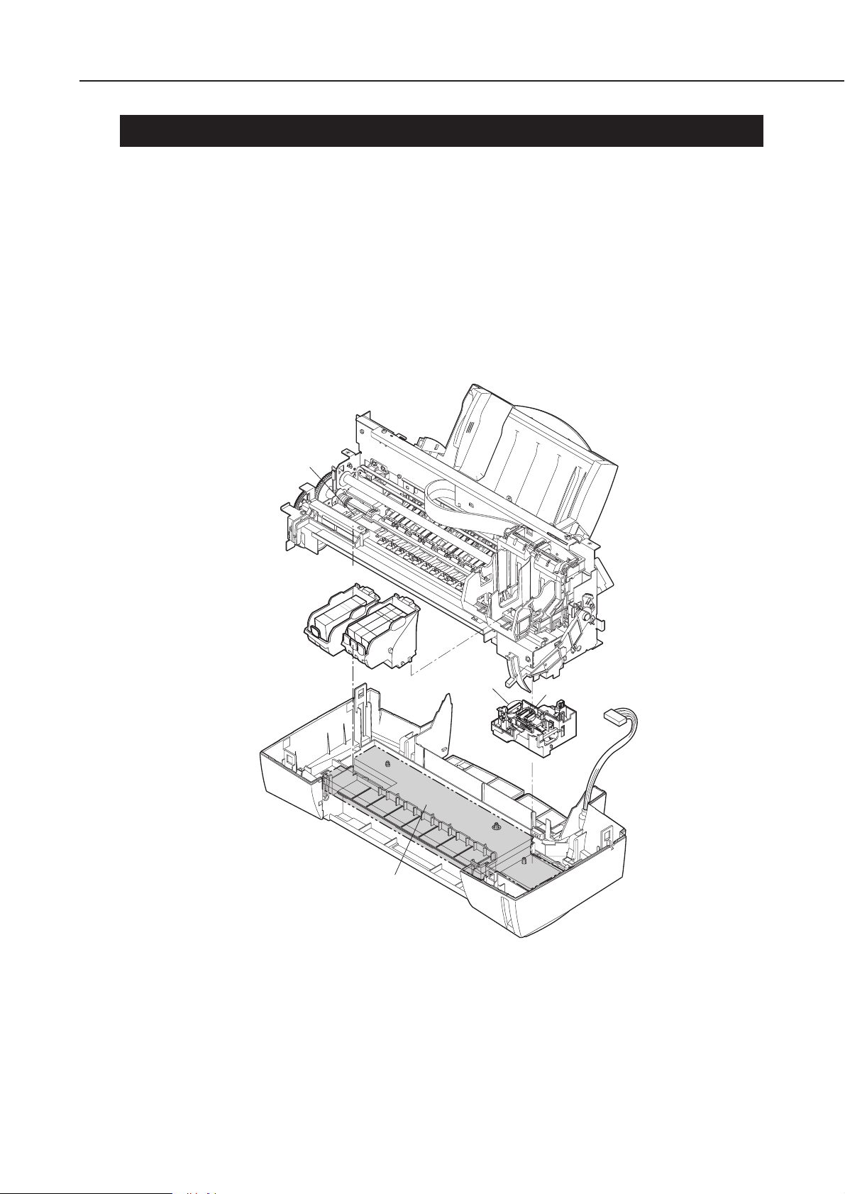
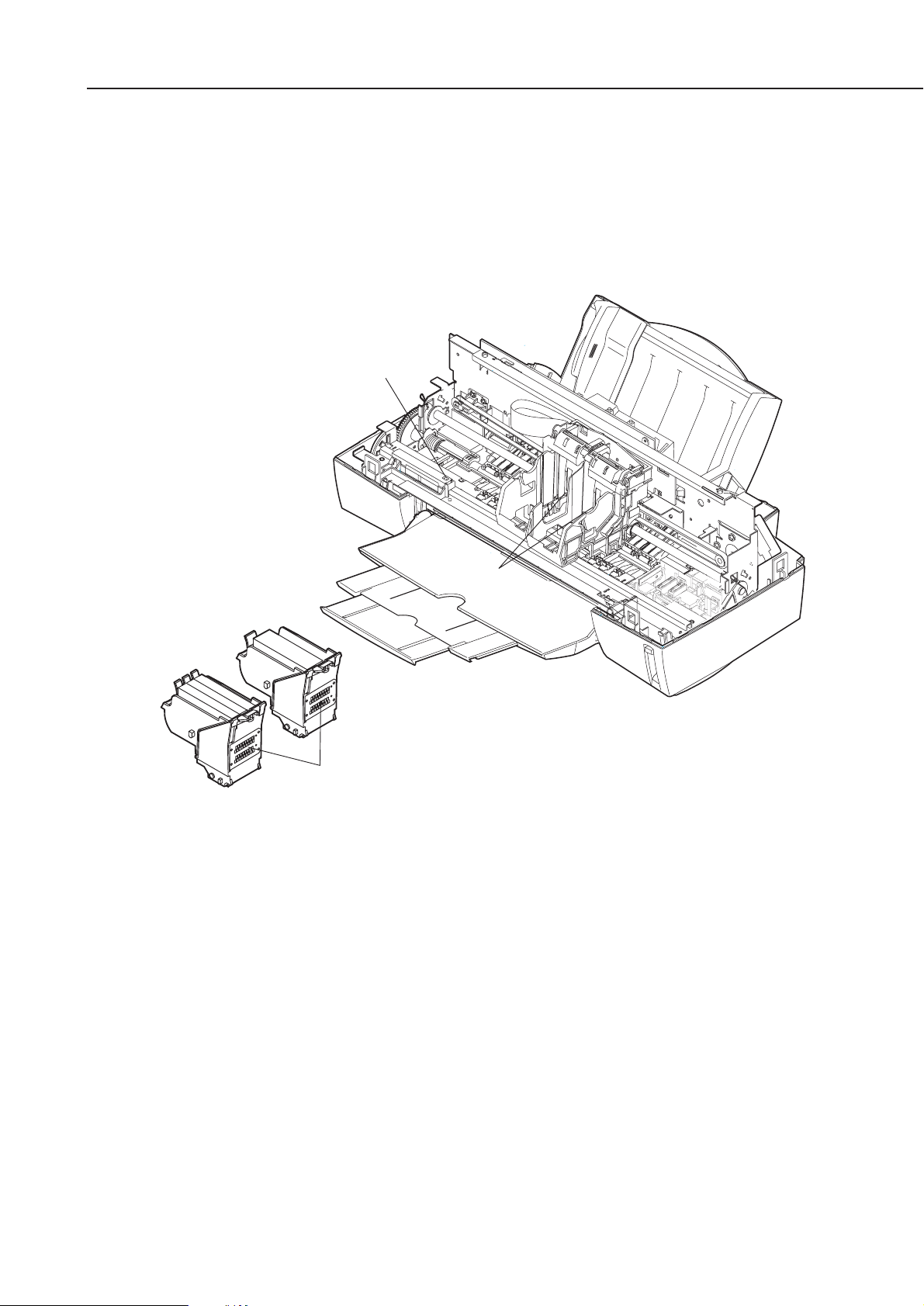
Be careful not to get your fingers, hair, clothing, or accessories caught in the moving
parts of the printer.
The moving parts are driven either by the carriage motor or paper feed motor. The
carriage motor-related moving parts include the carriage, carriage belt, and carriage
ribbon-cable. The paper feed motor-related moving parts include the paper feed gears,
paper feed rollers, pinch rollers, eject roller gears, spurs, and pick-up rollers.
To prevent injuries, the printer will stop after moving the carriage to the cartridge
replacement position if the cover is opened.
1-1
BJC-6000
Part 1: Safety and Precautions
Maintenance
Jet Receiving
Section
BJ Cartridges
Wiper
Head Cap
Waste Ink Absorber
Figure 1-1 The Printer's Moving Parts
1.2 Ink Stains
1.2.1 Ink paths
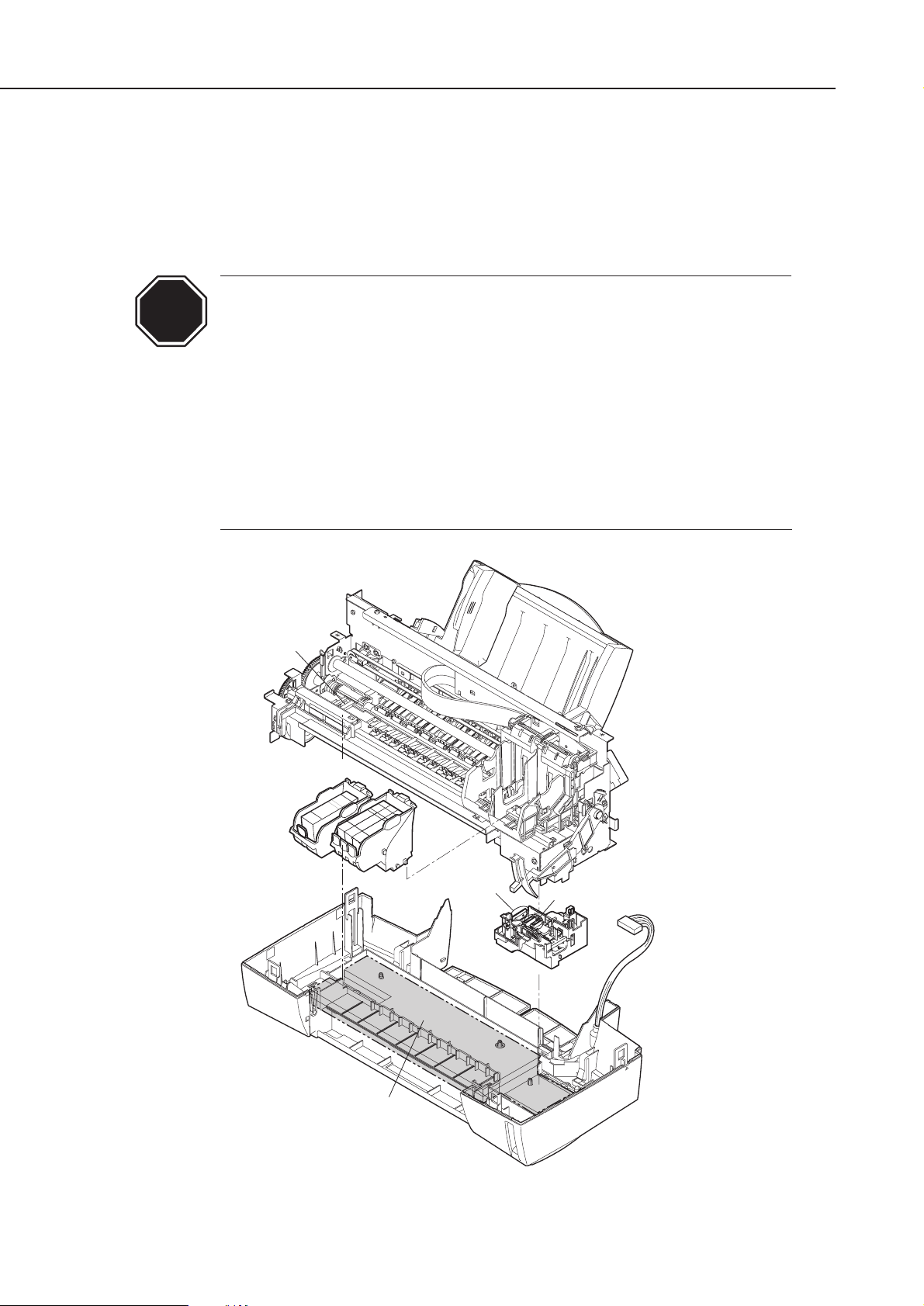
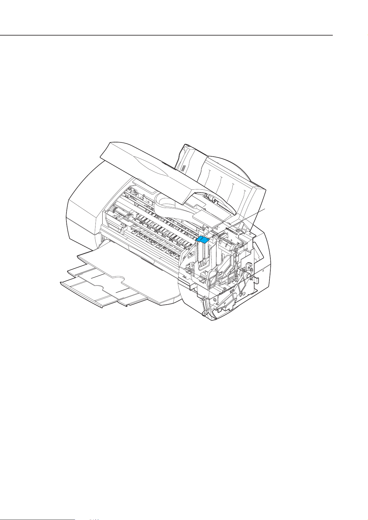
Be careful not to touch the ink paths. Ink on hands could stain the printer, work
table, or clothes. The ink paths include the BJ cartridge ink tank outlet, the BJ
cartridge ink filters and nozzles, the maintenance jet receiving section, the head caps,
the wipers, and the waste ink absorber.
The ink is not harmful to the human body, but contains some organic
solvents:
The black ink contains glycerin 56-81-5 and diethylene glycol 111-46-6.
The yellow ink contains glycerin 56-81-5 and isopropyl alcohol 67-63-0.
The cyan, magenta, photo-cyan, photo-magenta and photo-black ink
contain glycerin 56-81-5, isopropyl alcohol 67-63-0, ethylene glycol 10721-1, and diethylene glycol 111-46-6.
Be careful not to get the ink into your mouth or eyes. If the ink gets into
your eyes, wash with plenty of water and consult a doctor. In case you
have swallowed a large amount of ink, consult a doctor immediately.
The ink contains dyes. If clothing is stained with the ink, the ink may not
be removed completely.
Part 1: Safety and Precautions
BJC-6000
1-2
Maintenance
Jet Receiving
Section
BJ Cartridges
Wiper
Head Cap
Waste Ink Absorber
Figure 1-2 Ink Paths
CAUTION
1.2.2 Ink mist
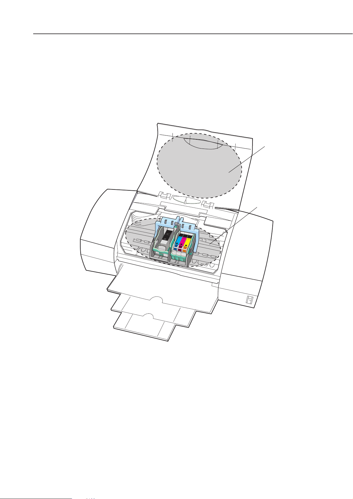
The BJ cartridge ejects ink onto the paper during printing. After the printer is used
for a long period or used heavily, part of the ink ejected from the nozzles, or ink mist
bouncing back from the paper could accumulate and contaminate the platen, front
cover, as well as the periphery of the purge unit. Carefully wipe off the ink mist with
a dampened soft cloth so that hands or clothing will not be stained by contaminated
parts during servicing.
1-3
BJC-6000
Part 1: Safety and Precautions
Front Cover
Platen
Figure 1-3 Ink Mist
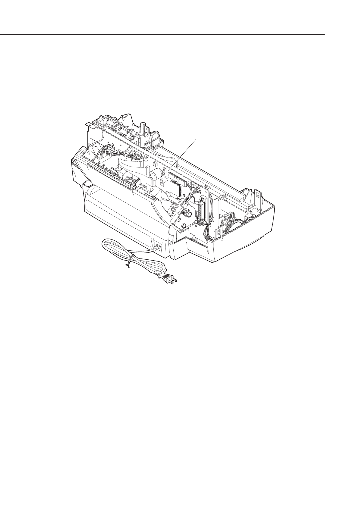
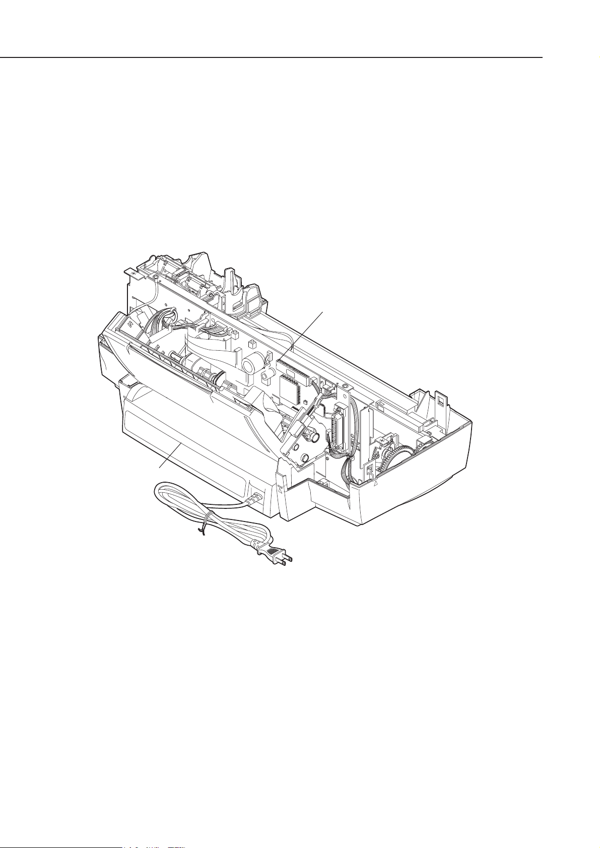
1.3 Live Electrical Parts
When the printer is plugged into a wall outlet, the power supply unit of the printer is
live, even if the power is switched off with the
POWER
button. Be careful not to get an
electric shock or damage sensitive elements if you are checking a live printer with the
cover removed.
Part 1: Safety and Precautions
BJC-6000
1-4
Control Board
Figure 1-4 Live Electrical Parts
2. MACHINE PRECAUTIONS
2.1 BJ Cartridges
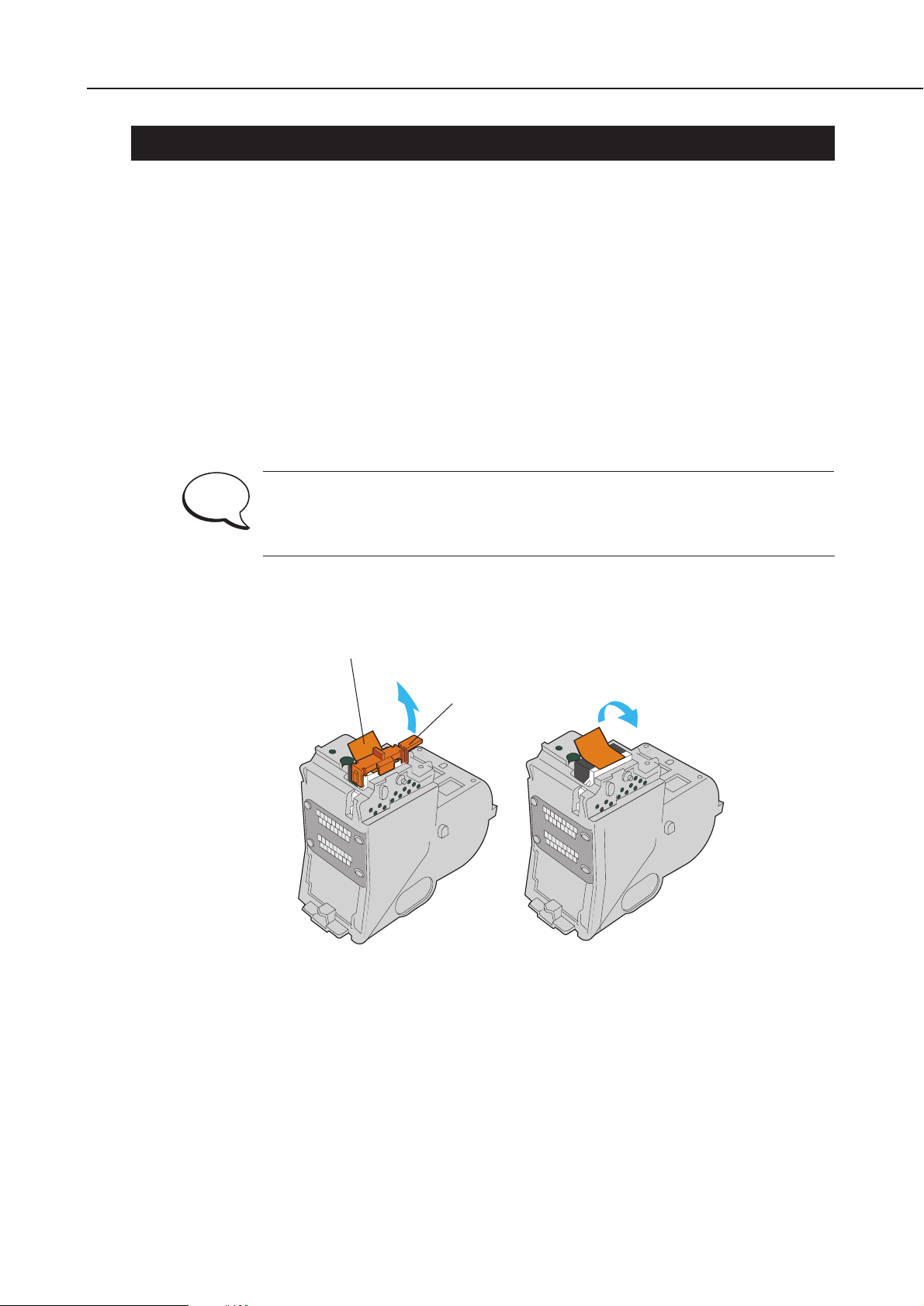
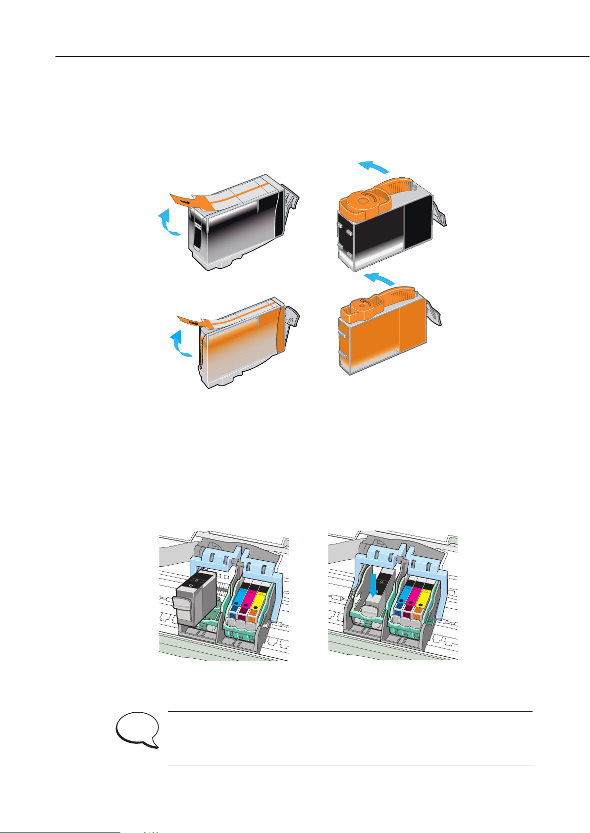
2.1.1 BJ cartridge handling
Do not unpack the BJ cartridge until you are ready to use it. Before installing the BJ
cartridge in the printer, carefully remove the head cap which protects the nozzles, the
protective tape, and the protective tank. To prevent the nozzles or other ink paths
from clogging, never touch or wipe the nozzles or other ink outlets with your bare
hands or tissue paper. After removing the head cap, the protective tape, and the
protective tank from a BJ cartridge, promptly install the cartridge in the printer or
store it in the cartridge container. Do not reuse head caps or protective tapes which
have been removed. The BJ cartridge must be installed in the printer or stored in the
cartridge container with its ink tanks installed. If the BJ cartridge is installed or
stored with its ink tanks removed, the nozzles could clog due to foreign matter or
dried ink. Do not attempt to disassemble or wash the BJ cartridge.
If a nozzle clogs, or ink fails to be fed normally, print quality degrades, and
typically a fine horizontal blank line appears in printed images. If cleaning
operations do not solve the problem, replace the BJ cartridge with a new
one.
1-5
BJC-6000
Part 1: Safety and Precautions
Protective Tape
Head Cap
Figure 1-5 BJ Cartridges
NOTE

2.1.2 Automatic capping
When the printer is turned off with the
POWER
button, it automatically caps the BJ
cartridge's nozzles to protect them as well as to prevent ink leakage. If the AC cable is
unplugged from a wall outlet before the printer is turned off with the
POWER
button,
the nozzles will not be automatically capped. In this case, plug in the AC cable again,
turn on the printer, and then turn it off with the
POWER
button. The nozzles will be
automatically capped.
If the nozzles are not capped, ink may dry out and clog the nozzles or leak
from the cartridge.
2.1.3 When not using the printer
The BJ cartridge may be either left installed in the printer or stored in the cartridge
container. This also applies when carrying, transporting, or storing the printer.
If the BJ cartridge is left in open air, out of the printer or cartridge
container, foreign matter or dried ink may clog the nozzles, resulting in
poor print quality.
2.1.4 Ink's electroconductivity
The ink in the BJ cartridge conducts electricity. If ink is spilt in the printer's
mechanical parts, use a dampened paper towel to wipe clean. If ink is spilt onto the
printer's electrical components, use tissue paper to wipe clean. If ink gets under an
IC chip on the control board and cannot be removed thoroughly, replace the control
board with a new one.
Never plug in the printer if its' electric circuitry is in contact with spilt ink.
Otherwise the electric circuitry could be damaged.
Part 1: Safety and Precautions
BJC-6000
1-6
CAUTION
CAUTION
CAUTION
2.2 Ink Tanks
2.2.1 Unpacking the ink tank
Do not unpack the ink tank until you are ready to use it. When installing it in the BJ
cartridge, unpack the ink tank, peel off the vinyl lamination, and remove the cap from
the ink outlets.
2.2.2 Ink tank handling
If the joint of the BJ cartridge connecting to the ink tank supply piece is contaminated,
suction of ink into the BJ cartridge could fail. Therefore, never touch the ink tank's
ink supply piece. After removing the cap from the ink tank supply piece, promptly
install the ink tank in the BJ cartridge to prevent the nozzles from clogging due to dried-ink.
Do not remove the ink tank from the BJ cartridge unless you are replacing it.
If a nozzle clogs, or otherwise ink fails to be fed normally, print quality
degrades, and typically a fine horizontal blank line appears in printed
images. If cleaning operations do not solve the problem, replace the BJ
cartridge with a new one.
1-7
BJC-6000
Part 1: Safety and Precautions
Figure 1-6 Unpacking the Ink Tank
Figure 1-7 Installing the Ink Tank
NOTE
2.3 Printer Handling
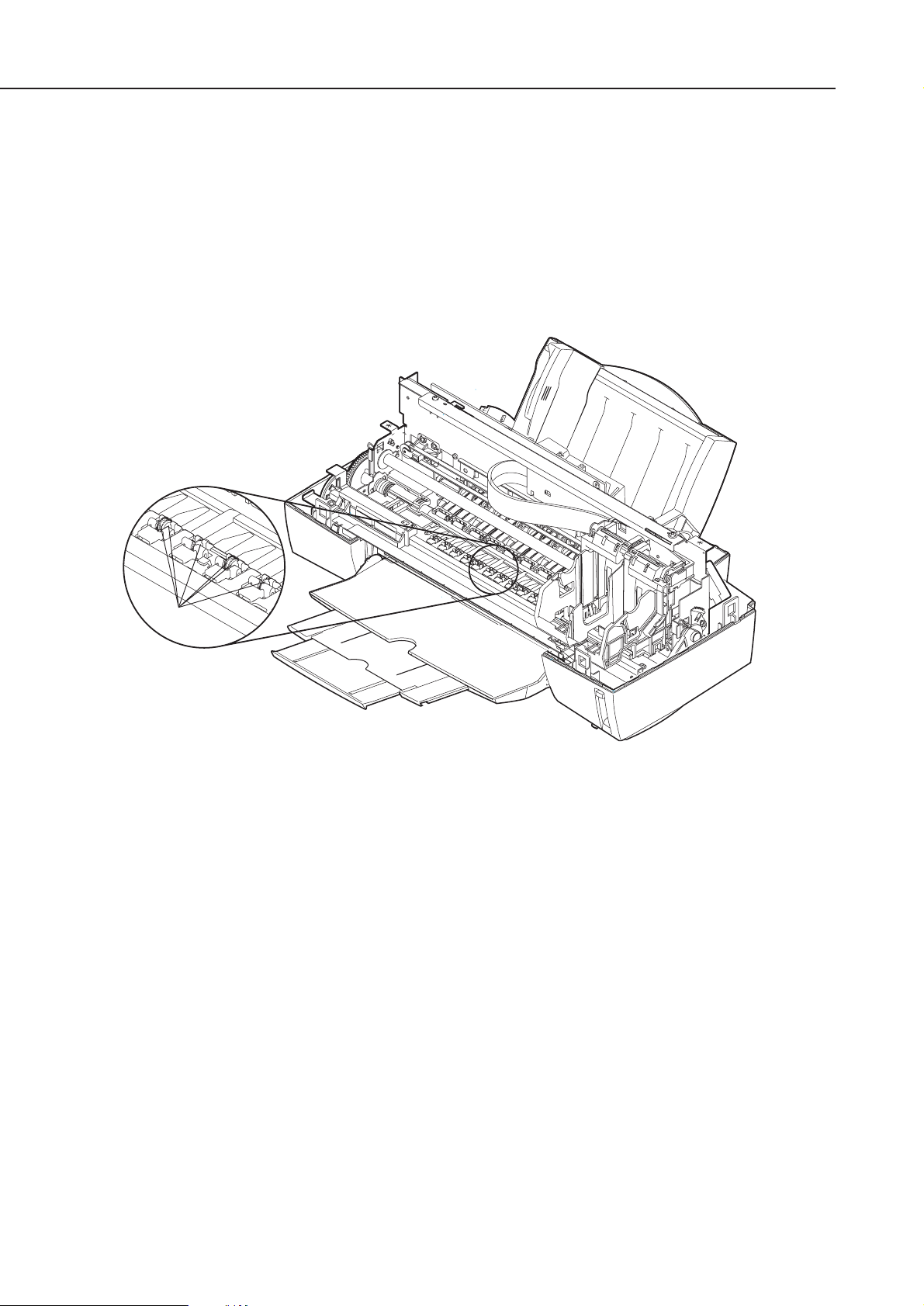
2.3.1 Spurs
Take care not to bend the tips of the spurs. The tips of the spurs make contact with
printed paper and are contaminated with ink, but due to their small surface contact
area, the tips, cleaned by the spur cleaners, will not stain the printed paper.
However, if the tips are bent and their surface contact area increases, they collect
more ink and are not easily cleaned by the spur cleaners, and thereby stain the
printed paper by making dotted lines on it.
Part 1: Safety and Precautions
BJC-6000
1-8
Spurs
Figure 1-8 Spurs
2.3.2 Damage due to static electricity
Static electricity may be generated by your clothes rubbing against each other and
may accumulate in your body. If you touch electrical elements, the discharge of static
electricity could damage them or change their electrical characteristics. For this
reason, never touch the sensor contacts or the printer's BJ cartridge contacts.
1-9
BJC-6000
Part 1: Safety and Precautions
Ink Sensor
Contact
Points
Contact Points
Figure 1-9 Damage Due to Static Electricity
2.3.3 Ink leakage prevention
When you turn off the printer using the
POWER
button, the printer moves the carriage
to the capping position, caps the nozzles, and locks the carriage in position with the
lock arm. If electric power is not available to the printer, during transportation for
example, this automatic capping and locking is not available. In this case, manually
move the carriage to the capping position and secure it with tape to ready the printer
for transportation.
Part 1: Safety and Precautions
BJC-6000
1-10
Tape
Figure 1-10 Capping Position
3. NOTES ON SERVICING
3.1 EEPROM Data
The printer keeps track of the total sheets printed by each BJ cartridge configuration
(Black/Color and Photo/Color) and the total waste ink amount and stores that
information in the EEPROM (IC 602) on the logic board. Observe the following
precautions during servicing:
1) Before servicing
You can check the EEPROM data with a test print. The total sheets printed by each
configuration can provide important information on how much the printer has been
used.
2) If the control board (EEPROM) is replaced (or if stored data is cleared by
mistake)
Check the waste ink absorber, and replace it with a new one if necessary. If you fail
to replace the waste ink absorber in time, the waste ink full alarm might not be
issued in time and waste ink could leak (depending on the current ink absorbing
capacity of the waste ink absorber). When replacing the logic board (EEPROM) with
a new one, be sure to clear the data on the new EEPROM, because the data is not
defined.
3) After the waste ink absorber is replaced
After replacing the waste ink absorber, as prompted by the waste ink full alarm,
clear the data on the EEPROM.
Once cleared, the EEPROM data cannot be restored (cannot be checked
with a test print). Always check the EEPROM data with a test print before
clearing it. The data includes information on the user settings, the total
sheets of printed paper and the total amount of waste ink absorbed. Note
that you cannot edit the data from the operator panel.
The printer calculates the total amount of waste ink absorbed based on
the estimated usage of the printer. To prevent the capacity of the waste
ink absorber from being exceeded, the waste ink full alarm is issued when
the waste ink absorber gets full, suspending the operation of the printer.
Refer to
Part 3: 3.6.4 Resetting EEPROM
(Page 3-21) for the procedures for
checking the EEPROM data with a test print or for clearing the data.
Refer to
Part 5: 6. TROUBLESHOOTING
(Page 5-13) for the troubleshooting
procedures to be followed when the waste ink full alarm is issued.
1-11
BJC-6000
Part 1: Safety and Precautions
CAUTION
REF.
3.2 Static Electricity
Static electricity may be generated by your clothes rubbing against each other and may
accumulate in your body. If you touch electrical elements, the discharge of the static
electricity could damage them or change their electrical characteristics. To prevent
damage due to such electrostatic discharge, ground yourself by touching a metal fitting
which is grounded before disassembling or otherwise servicing the printer.
Part 1: Safety and Precautions
BJC-6000
1-12
Control Board
AC Adapter
Figure 1-11 Control Board and Other Electrical Components
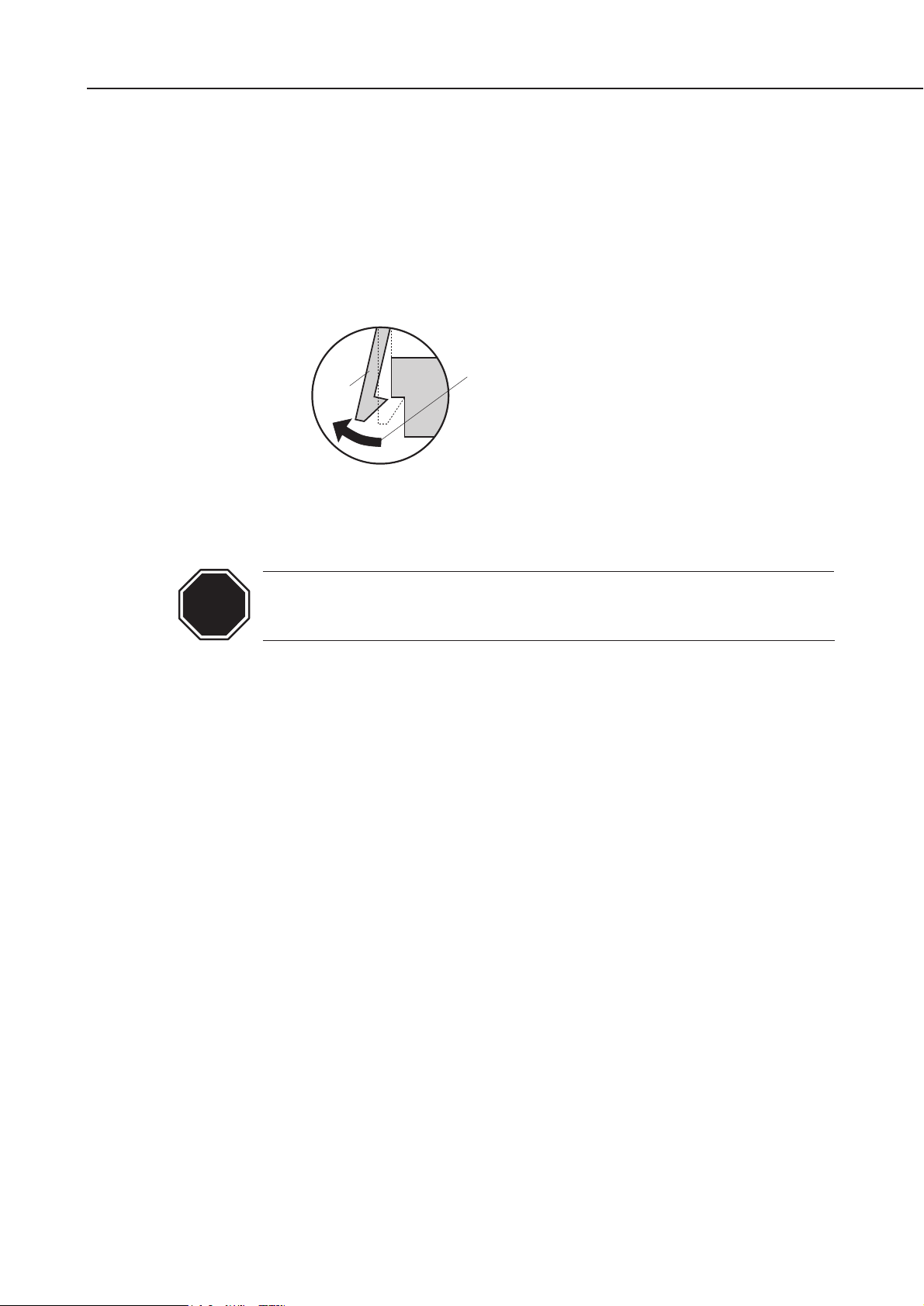
3.3 Disassembly and Reassembly
Disassembly and reassembly must be done according to the relevant parts catalog,
which illustrates the step-by-step procedures to be followed. Additional notes are
provided in
Part5: 4. DISASSEMBLY AND REASSEMBLY
(Page 5-4).
The printer uses many plastic parts. Do not apply excessive force to them. In
particular, take care not to break or deform plastic hooks during disassembly.
Some plastic parts contain glass fibers to conform to tight dimensional
tolerances. Plastic hooks are among such parts, lacking flexibility, and
are easily broken. Do not forcibly disengage them using a screwdriver.
1-13
BJC-6000
Part 1: Safety and Precautions
Hook
Never apply excessive force
when releasing a hook.
Figure 1-12 How to Disengage a Plastic Hook
CAUTION

3.4 Self Diagnosis
The printer has self-diagnosis features to detect hardware defects. The results of the
diagnosis are indicated by the
indicator
and
power lamp (flashing)
on the operator panel as
well as by the buzzer. For details, refer to
Part 3: 3.1 Error Indications
(Page 3-12).
Part 1: Safety and Precautions
BJC-6000
1-14

Part 2
PRODUCT
SPECIFICATIONS
Page
2 - 1 1. PRODUCT OUTLINE
2 - 1 1. 1 Outline
2 - 2 1.2 Features
2 - 3 1.3 BJ Cartridge
2 - 4 1.4 BJ Cartridge Container
2 - 5 1.5 Consumables
2 - 6 2. SPECIFICATIONS
2 - 6 2.1 General Specifications
2 - 8 2.2 Paper Specifications
2 -10 2.3 Interface Specifications
1. PRODUCT OUTLINE
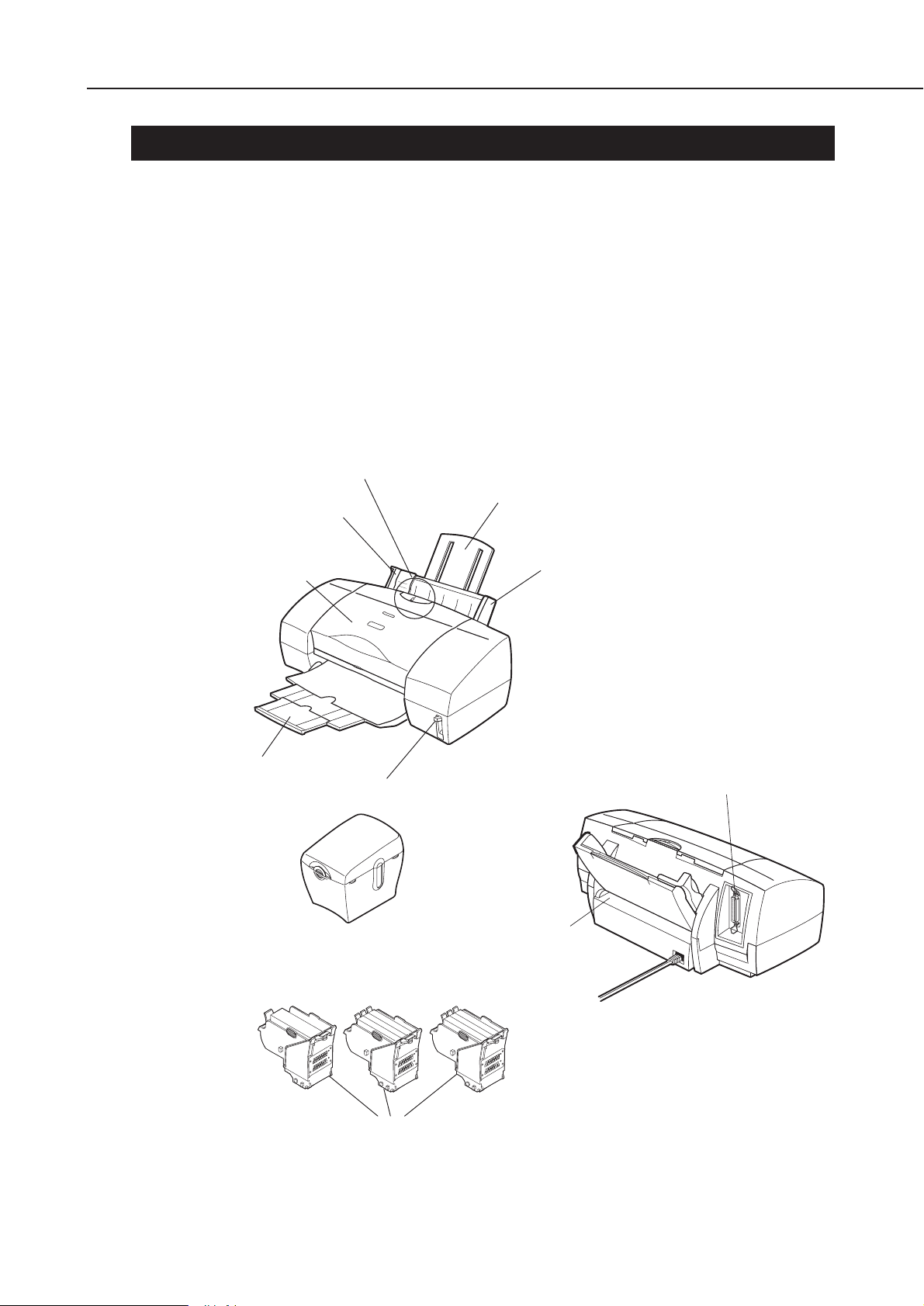
1.1 Outline
This printer is a desktop business/personal color bubble-jet printer for high
speed/high quality use. It accommodates two "drop-modulation" BJ cartridges on its
carriage. For high speed use, a pigment-Black BJ cartridge and a Color BJ cartridge
combination achieves four-color printing for quality equal to a laser printer. For high
quality use, a Color BJ cartridge and Photo BJ cartridge combination achieves six-color
printing whose quality is as good as a color photograph. The BJ cartridges use ink
tanks which can be replaced individually, and whose tank material is translucent for
easier ink level checking, contributing to lower running cost.
2-1
BJC-6000
Part 2: Product Specifications
Operator Panel
Paper Guide
Front Cover
Paper Output Tray
Paper Thickness Lever
Cartridge Container
BJ Cartridges
Paper Support
Auto Sheet Feeder
Parallel Interface Connector
Manual Feed Slot
Figure 2-1 Printer Appearance

1.2 Features
á Laser-printer quality using pigment black ink
á Dual-cartridge system
High quality printing at high speed from a combination of the Black and Color
cartridges or the Color and Photo cartridges
Black BJ cartridge: Drop modulation, replaceable ink tank (pigment black), 160 nozzle
head
Color BJ cartridge: Drop modulation, individually replaceable ink tanks (yellow,
magenta and cyan), 144 in-line nozzle head (48 nozzles for each of
three colors)
Photo BJ cartridge: Drop modulation, individually replaceable ink tanks (dye black,
photo-magenta and photo-cyan), 144 in-line nozzle head (48
nozzles for each of three colors)
á Individually replaceable ink tanks for high cost performance
Black ink tanks: Pigment black ink tank
Color ink tanks: Yellow, magenta, and cyan ink tanks
Photo ink tanks: Dye black, magenta, and cyan ink tanks
á Ink-out detection, and translucent ink tanks for easier ink level checking
á High speed printing (8.0 PPM black printing or 5.0 PPM color printing in HS mode)
á 1440 x 720 dpi high resolution printing
á Automatic printing position adjustment
Ensures accurate printing position regardless of cartridges being used or carriage
movement direction
á Supports a wide variety of print media
á Up to A4/Letter full-bleed size paper and banner paper can be used
á Blue Angel compliant
Part 2: Product Specifications
BJC-6000
2-2
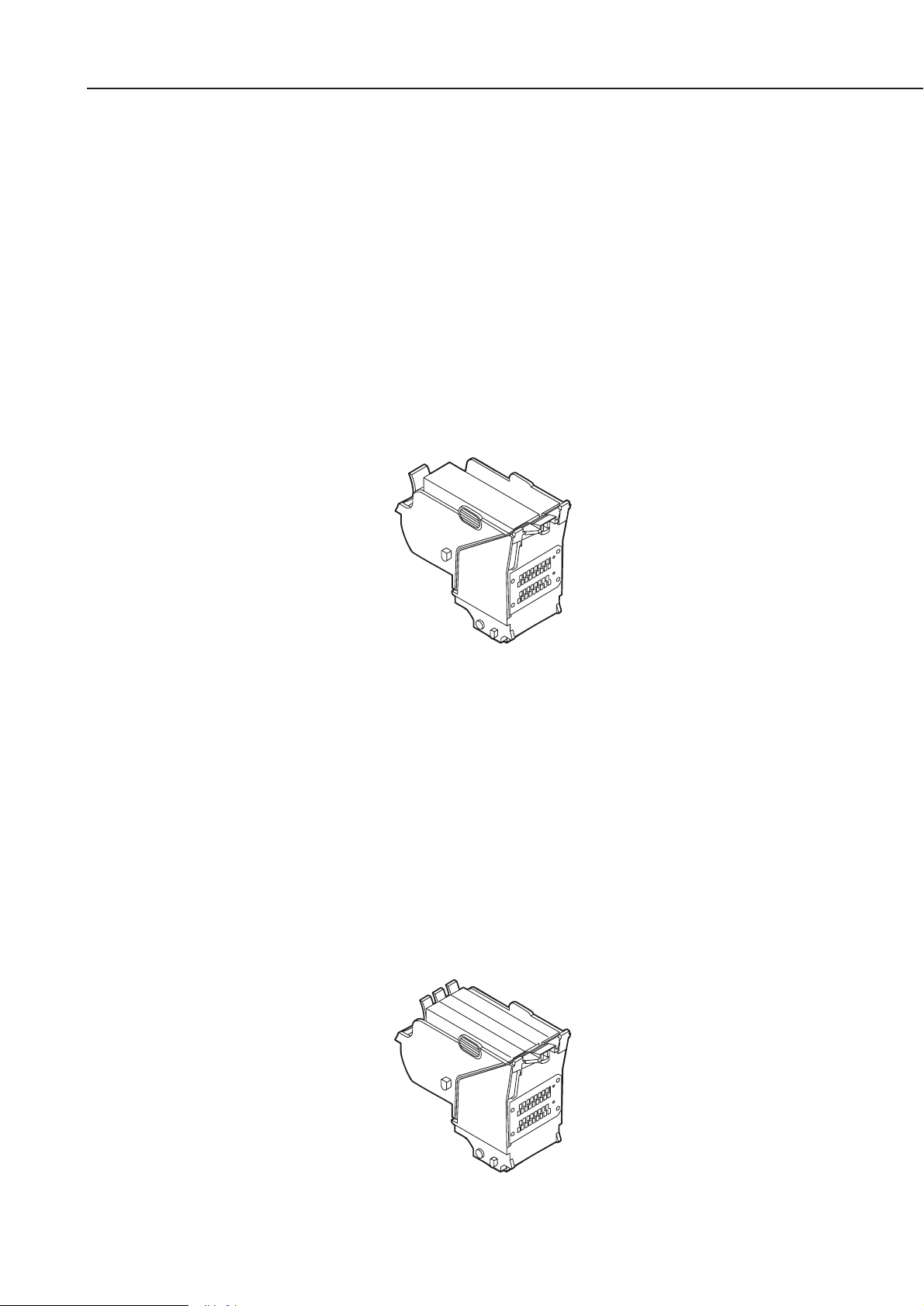
1.3 BJ Cartridge
1.3.1 Black BJ cartridge
The Black BJ cartridge is to be mounted on the left side of the carriage for high speed
color/monochrome printing. It is a disposable print head. It has 160 nozzles and
accommodates a replaceable ink tank. It uses drop modulation technology for high
speed, high quality printing, where smaller ink-droplets are discharged for low density
images and larger ink-droplets for denser images. The pigment black ink is water
resistant and allows for dense and sharp text printing.
Replace the ink tank and/or the Black BJ cartridge if the ink-out error is issued or if
satisfactory printing cannot be achieved even after the stipulated cleaning and head
refreshing operations have been performed. It is recommended to replace any
cartridge which is at least six months old, i.e., unpacked at least six months prior.
The Black BJ cartridge has a life of approximately 5000 pages, and a new black ink
tank provides for approximately 500 pages of a standard 1500 character print pattern
in HQ mode.
1.3.2 Color BJ cartridge
The Color BJ cartridge, mounted on the right side of the carriage, is a disposable print
head with 144 in-line nozzles, and accommodates replaceable yellow, magenta and
cyan ink tanks. It has 144 nozzles (48 nozzles for each of the three colors), aligned
vertically. It uses drop modulation technology for high speed, high quality printing,
where smaller ink-droplets are discharged for low density images and larger inkdroplets for denser images. Each color ink is a dye-type.
Replace the relevant ink tank and/or the Color BJ cartridge if the ink-out error is
issued or if satisfactory printing cannot be achieved even after the stipulated cleaning
and head refreshing operations have been performed. It is recommended to replace
any cartridge which is at least six months old, i.e., unpacked at least six months
prior. The Color BJ cartridge has a life of approximately 3000 pages and a new color
ink tank provides for approximately 280 pages of a 7.5% duty pattern.
2-3
BJC-6000
Part 2: Product Specifications
Figure 2-3 Color BJ Cartridge
Figure 2-2 Black BJ Cartridge
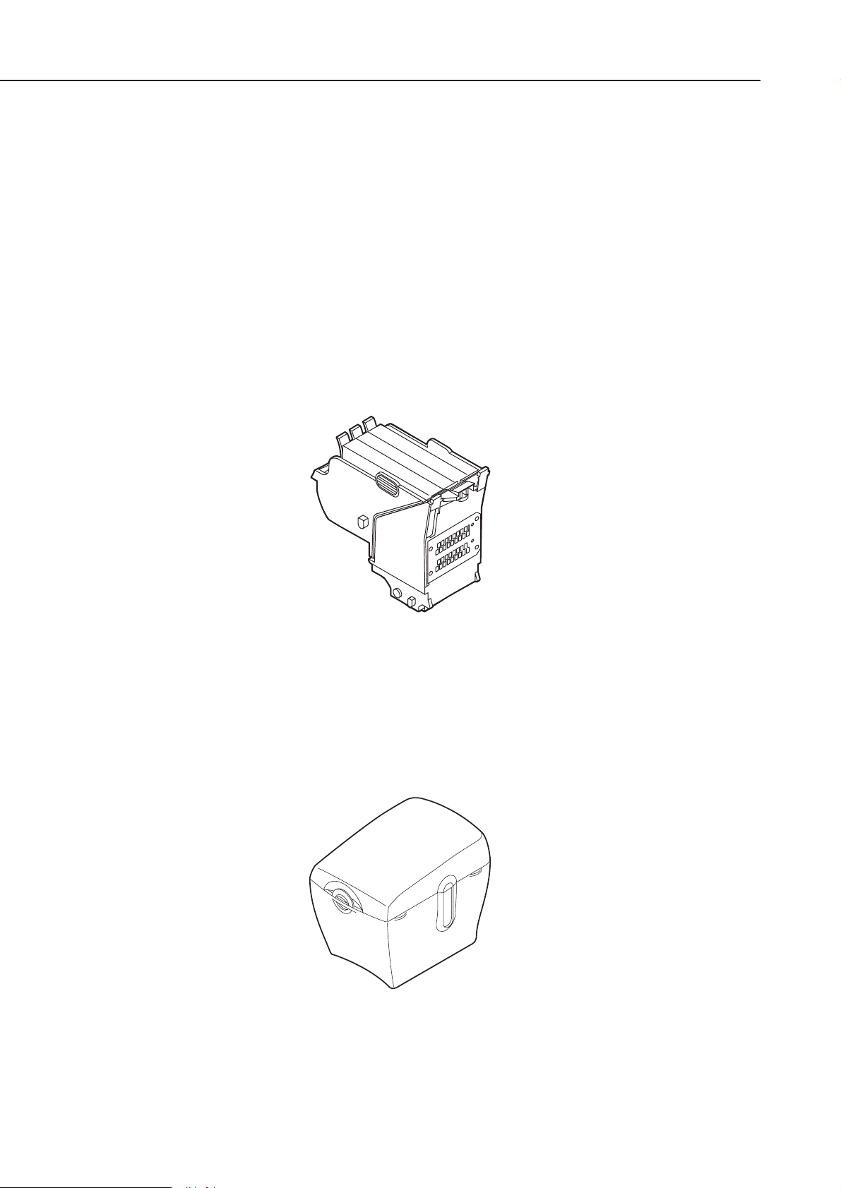
1.3.3 Photo BJ cartridge
The Photo BJ cartridge, mounted on the left side of the carriage for photo printing, is
a disposable print head with 144 in-line nozzles, and accommodates replaceable
photo-black, photo-magenta and photo-cyan ink tanks. It has 144 nozzles (48 nozzles
for each of the three colors), aligned vertically. It uses drop modulation technology for
high speed, high quality printing, where smaller ink-droplets are discharged for low
density images and larger ink-droplets for denser images. The black ink is a dye-type
and the photo-cyan and photo-magenta inks are three times lighter in color density
than normal color inks.
Replace the relevant ink tank and/or Photo BJ cartridge if the ink-out error is issued
or if satisfactory printing cannot be achieved even after the stipulated cleaning and
head refreshing operations have been performed. It is recommended to replace any
cartridge which is at least six months old, i.e., unpacked at least six months earlier.
The Photo BJ cartridge has a life of approximately 3000 pages and a new color ink
tank provides for approximately 280 pages of a 7.5% duty pattern.
1.4 BJ Cartridge Container
The BJ cartridge container is used to store non-installed BJ cartridges. The lid of the
container must be closed fully to prevent the ink in the nozzles of the BJ cartridge from
drying out. Each BJ cartridge container can store one Black, Color, or Photo BJ
cartridge. Always store a BJ cartridge with its ink tanks installed. The BJ cartridge
containers can be connected together.
Part 2: Product Specifications
BJC-6000
2-4
Figure 2-5 BJ Cartridge Container
Figure 2-4 Photo BJ Cartridge
 Loading...