

Canon BJC-4400 Parts Catalog

0199 xx 0.00-O

Application
This manual has been issued by Canon Inc. for qualified
person to learn technical theory, installation, maintenance,
and repair of products. This manual covers all localities
where the products are sold. For this reason, there may be
information in this manual that does not apply to your
locality.
Corrections
This manual could include technical inaccuracies or
typographical errors due to improvements or changes in the
products. When changes occur in applicable products or in
the content of this manual, Canon will release technical
information as thelneed arises. In the event of major 1
changes in the contents of this manual over a long or short
period. Canon will issue a new editions of this manual.
The following paragraph does not apply to any countries
where such provisions are inconsistent with local low.
Trademarks
The product names and company names described in this
manual are the registered trademarks of the individual
companies.
Copyright
This manual is copyrighted with all rights reserved. Under
the copyright laws, this manual may not be copied,
reproduced or translated into another language, in whole or
in part, without the written consent of Canon Inc.
Copyright 0 1999 by Canon -Inc.
CANON INC.
BJ Printer Technical Support Dept.
16-1, Shimonoge’ 3=chome, Takatsu-ku, Kawasaki-shi,
Kanagawa 213-8512, Japan
DTP System
This manual was produced on an Apple@ Power Macintosh@
G3 personal computer and Canon LBP-203OPS laser beam
printer, final pages were printed on Valityper@ 43003.
A Canon mo-SOON” Magneto-optical Storage Subsystem
with mo-502M” Magneto-Optical Storage Disk Cartridge
and mo-IF2- Machitosh* interface kit were used for storing
large volumes of page layout, graphic and parts list data for
this manual.
Parts layout illustrations and Logotypes were created using
MACROMEDIA@ FreeHand@ 75.
Pattern drawing were scaned by CanoScan 600 scanner with
Adobe@ photoshop?
Documents and page layouts were created using
QuarkXpress@ 3.35.
Parts lists were created using Helix Tecnologies@ Herix
Xpress@ and converted to EPS files.
Hi%
$-==7ILCr)K&W *?-I ~~&$$$&CZ$$@&~
WWO *“rI ‘J~&&~~a>~i%kQ~~~$W~
+$trca, *~~=7IL0--$$atj~~~C~. +@%?@z&d
754;f;. $GiFL #WE,”
“=~a>@j$@$~~.&-~$L~W~-$-.

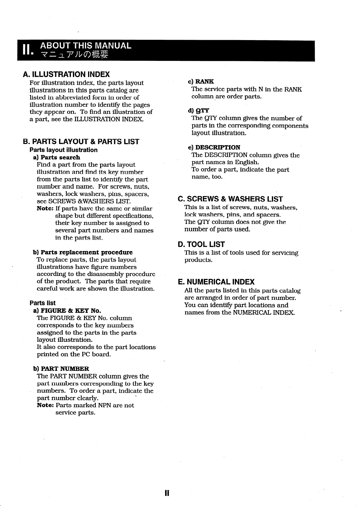
A. ILLUSTRATION INDEX
For illustration index, the- parts layout
illustrations in this parts catalog are
listed in abbreviated form in order of
illustration number to identify the pages
they appear on. To find an illustration of
a part, see the ILLUSTRATION INDEX.
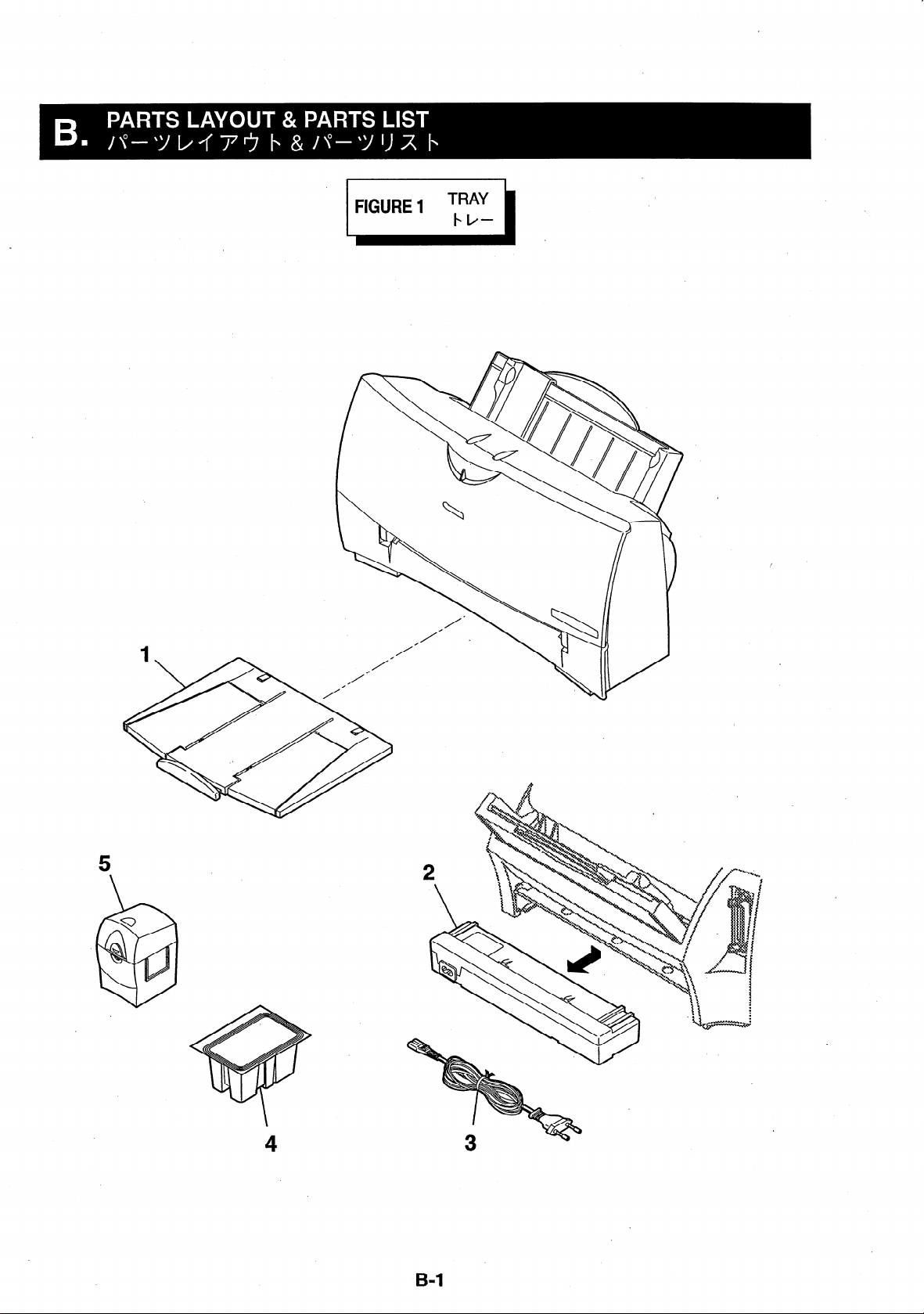
B. PARTS LAYOUT & PARTS LIST
Parts layout illustration
a) Parts search
Find a part from the parts layout
illustration and find its key number
from the parts list to identify the part
number and name. For screws, nuts,
washers, lock washers, pins, spacers,
see SCREWS &WASHERS LIST.
Note: If parts have the same or similar
shape but different specifications,
their key number is assigned to
several part numbers and names
in the parts list.
b) Parts replacexrient procedure
.
To replace parts, the parts layout
illustrations have figure numbers
according to the disassembly procedure
of the product. The parts that require
careful work are shown the illustration.
Parts list
a) FIGURE % KEY No.
The FIGURE & KEY No. column
corresponds to the key numbers
assigned to the parts in the parts
layout illustration.
It also corresponds to the part locations
printed on the PC board.
The service parts with N in the RANK
column are order parts.
The Q’IY column gives the number of
parts in the corresponding components
layout illustration.
e) DESCRIPTION
The DESCRIPTION column gives the
part names in English.
To order a part, indicate the part
name, too.
C. SCREWS & WASHERS LIST
This is a list of screws, nuts, washers,
lock washers, pins, and spacers.
The QTY column does not give the
number of parts used.
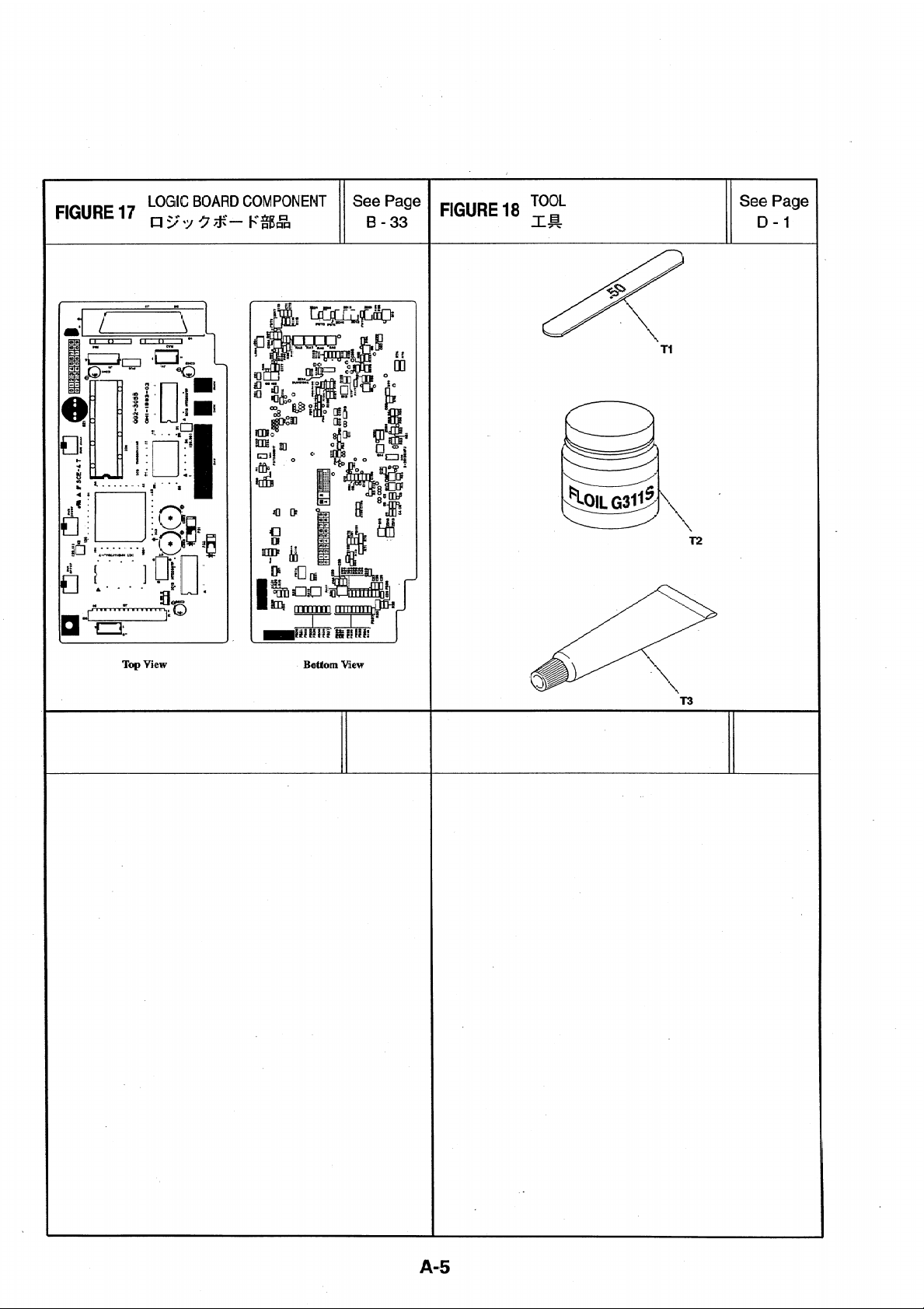
D. TOOL LIST
This is a list of tools used for servicing
products.
E. NUMERICAL INDEX
All the parts listed in this parts catalog
are arranged in order of part number.
You can identify part locations and
names from the NUMERICAL INDEX
f
b) PART NUMBER
The PART NUMBER column gives the
part numbers corresponding to the key
numbers. To order a part, indicate the
part number clearly.
Note: Parts marked NPN are not
service parts.
_


=IGURE 5
SHEET FEEDER UNIT
se; ‘;ge FIGURE 6 ;FgRICAL pARTs
>-fqq--I_=l*y p -
See Page
B- 11
FIGURE 7
BOTTOM CASE & PURGE UNIT
~~-~&Jf-*i”l=y b
See Page FIGURE 8 WASTE INK ABSORBER See Page
B-13
~-I=/mt@~
B-15
i
A-2
e Page
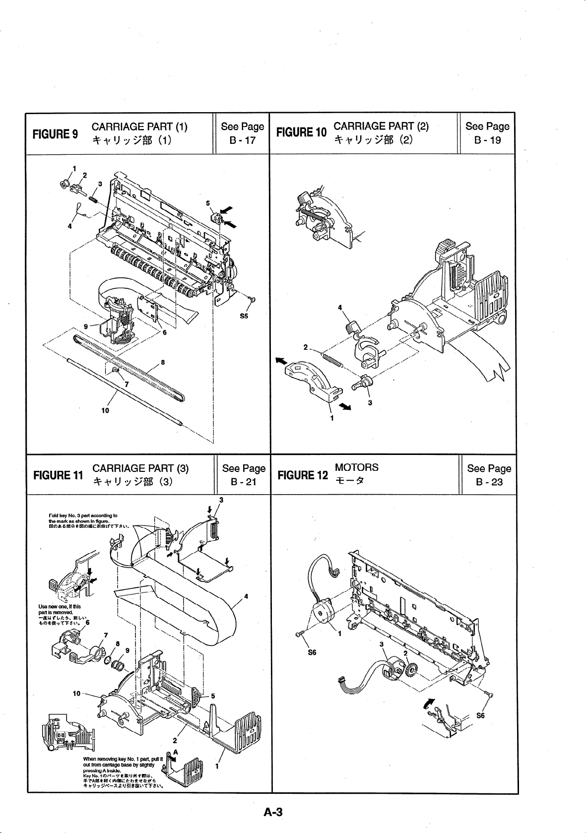
3-19
3e Page
B - 23
A-3

This page intentionally left blank
9 e_:+
Ea
/
A-6
5
1
B-l
FIGURE
&
KEY NO.
R
PARTNUMBER “N T
K
Q
Y
DESCRIPTION
REMARKS
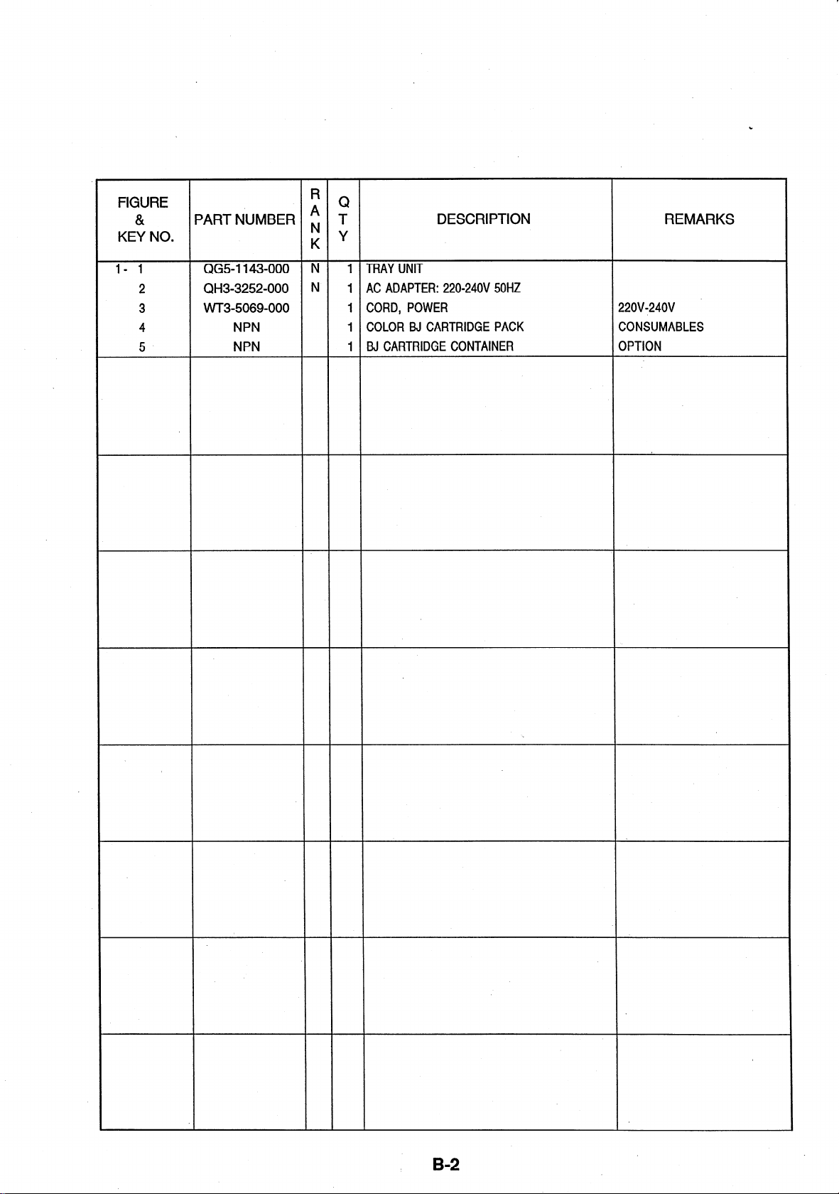
l- 1
2 QH3-3252-000 N
3 VVT3-5069-000
4
5
QG51143-000 N
NPN
NPN
1 TRAY UNIT
1 AC ADAPTER: 2200240V 50HZ
1 CORD, POWER
1 COLOR BJ CARTRIDGE PACK CONSUMABLES
1 BJ CARTRIDGE CONTAINER OPTION
22OV-240V .
B-2
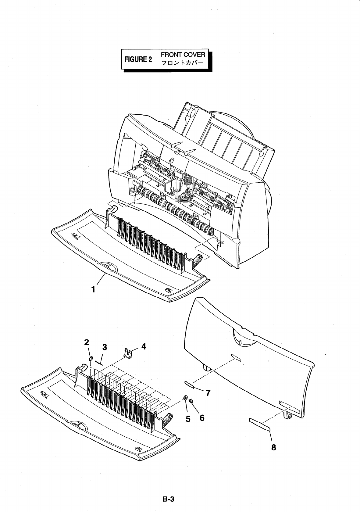
FIGURE 2
FRONT COVER
7a> MIC-
B-3
FIGURE
&
KEY NO.
R
PARTNUMBER ; T
K
Q
Y
DESCRIPTION
REMARKS
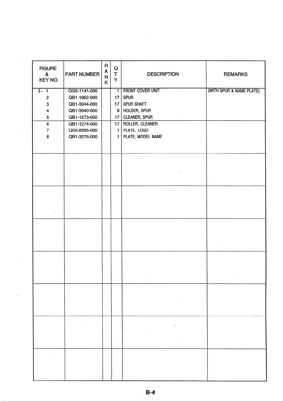
2-1
2
3
4 QBI -3040-000
5
6
7
8
QG5-1141-000
QBI -1952-000
QBI -3044-000
QBI -1273-000
QBI-I 274-000
QS5-8265-000
QBI -3276-000
I
1 FRONT COVER UNIT (WITH SPUR & NAME PLATE)
17 SPUR
17 SPURSHAFT
9 HOLDER, SPUR
17 CLEANER, SPUR
17 ROLLER, CLEANER
1 PLATE, LOGO
1 PLATE, MODEL NAME
.
. B-4
s

When removing the key No. 1 part,
remove the top claws first.
When reassembling, reassemble
the bottom claws first.
Key No. 1 HlUl9t~~i;f:. _k$lflE%tZ
34 lJT+L’, #4LsMs%I~, -Ftm
5t;Cam;AhTT $5 L’,
1
FIGURE
&
KEY NO.
R
PARTNUMBER ; T
K
Q
Y
DESCRIPTION
REMARKS
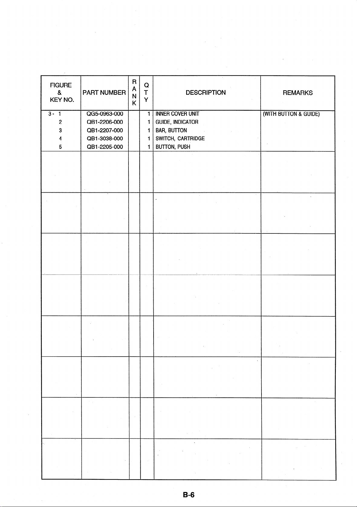
3- 1
2 QBI -2206-000 1 GUIDE, INDICATOR
3 QB I-2207-000 1 BAR, BUTTON
4 QBI -3038-000 1 SWITCH, CARTRIDGE
5 QBI -2205000 1 BUTTON, PUSH
QG50963-000
.
1 _ INNER COVER UNIT
(WITH BUTTON & GUIDE)
B=6
 Loading...