

Page 1
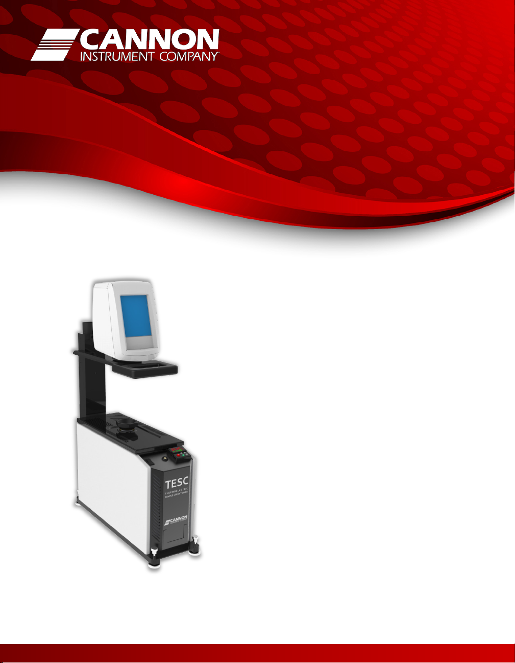
TESC
P/N 17.5125
CANNON® TESC
Thermoelectric Sample Conditioner System
For low temperature viscosity of lubricants
ASTM D2983
Operator’s Manual
Revision 1.0, November 20, 2014
Page 2

Page 3

Thermoelectric Sample Conditioner System
CANNON Instrument Company®
Operator’s Manual
Revision 1.0, November 20, 2014
2139 High Tech Road
State College, PA 16803
Page 4

ii
CANNON®
TESC Operator's Manual, Rev 1.0
Revision
Date
Details
Revision 1.0
November 20, 2014
Preliminary release
Copyright
Copyright © 2014 CANNON Instrument Company®. All rights reserved.
Trademarks
CANNON®, the CANNON® logo, CANNON Instrument Company ®, and VISDISK® are
registered trademarks of CANNON Instrument Company® in the United States and other
countries.
Brookfield® is a registered trademark of Brookfield® Engineering Laboratories, Inc. in the
United States and other countries.
Watlow® is a registered trademark of Watlow® Electric Manufacturing Company in the United
States and other countries.
Microsoft®, Windows®, and Excel® are registered trademarks of Microsoft® Corporation in the
United States and other countries.
Revision History
Contact
Address: CANNON Instrument Company®
2139 High Tech Road
State College PA 16803, USA
Phone: 1-814-353-8000; 1-800-676-6232
Fax: 1-814-353-8007
Website: http://www.cannoninstrument.com
Email:
Sales: sales@cannoninstrument.com
Service: service@cannoninstrument.com
Page 5

iii
CANNON®
TESC Operator's Manual, Rev 1.0
Contents
Overview........................................................................................................................... 1
Theory of operation ...................................................................................................................... 1
Related documents ....................................................................................................................... 2
Specifications / Compliances ........................................................................................................ 3
Notes/Cautions/Warnings ............................................................................................................. 4
Safety precautions ........................................................................................................................ 4
Getting Started ................................................................................................................. 7
Unpack and inspect ...................................................................................................................... 7
Setup the TESC System ................................................................................................................ 8
Assemble the TESC System ...................................................................................................... 8
Connect cables ....................................................................................................................... 10
Run quick verification test .......................................................................................................... 12
Running an ASTM D2983 Test ........................................................................................... 15
Calibrating the TESC System ............................................................................................ 19
Watlow® controller calibration ................................................................................................... 20
Install Watlow® configurator program .................................................................................... 20
Calibration procedure ............................................................................................................. 21
Brookfield® DV2T temperature probe offset adjustment ........................................................... 24
Specifications .................................................................................................................. 25
Warranty ......................................................................................................................... 27
Products limited warranty ...........................................................................................................27
Reagent and chemical warranty ..................................................................................................27
Returning a product to CANNON® ............................................................................................. 28
Required information .............................................................................................................. 28
Hazardous materials ............................................................................................................... 28
Shipping notification .............................................................................................................. 28
Replacement Parts List ..................................................................................................... 29
Page 6

iv
CANNON®
TESC Operator's Manual, Rev 1.0
List of Figures
Figure 1 — Assembled TESC System ................................................................................................. 9
Figure 2 — TESC with Watlow® controller ...................................................................................... 10
Figure 3 — Brookfield® DV2T connections ...................................................................................... 11
Figure 4 — TESC connections ......................................................................................................... 11
List of Tables
Table 1 — TESC Thermal conditioning programs .............................................................................. 2
Table 2 — Related documents .......................................................................................................... 2
Table 3 — Specifications and compliances ........................................................................................ 3
Table 4 — Packing list (TESC System) ............................................................................................... 7
Table 5 — Packing list (accessories) .................................................................................................. 8
Table 6 — Tools and materials required ............................................................................................ 8
Table 7 — Tools and materials required .......................................................................................... 12
Table 8 — Tools and materials required .......................................................................................... 15
Table 9 — Thermal conditioning programs ..................................................................................... 16
Table 10 — Viscosity measurement programs ................................................................................ 17
Table 11 — Watlow® offset example ............................................................................................... 19
Table 12 — Brookfield® offset example .......................................................................................... 20
Table 13 — Tools and materials required ......................................................................................... 20
Table 14 — Specifications ............................................................................................................... 25
Table 15 — TESC System replacement parts ................................................................................... 29
Table 16 — Standards ..................................................................................................................... 29
Page 7

1
CANNON®
TESC Operator's Manual, Rev 1.0
Overview
CANNON®’s Thermoelectric Sample Conditioner (TESC) System provides controlled sample
heating and cooling for ASTM D2983. Low cost and a small footprint, compared to other
sample conditioning options, allow several complete TESC Systems to be conveniently
operated in the same bench-top area as a single competitor unit. This gives labs optimal test
versatility and redundancy to maximize productivity and reduce downtime.
Theory of operation
The TESC System uses a method equivalent to Procedure B of ASTM D2983. To reduce test
variability, the TESC System automates or removes many of the steps required to transfer the
sample between conditioning and testing processes. Automation occurs through use of a
thermoelectrically controlled sample chamber that manages the sample, without operator
intervention, throughout the conditioning and testing processes.
Using a calibrated TESC System, an operator runs a D2983 test as follows:
1. Auto-zero the Brookfield® DV2T viscometer.
2. Measure 20 mL of sample into a 25 mm × 150 mm, rimless test tube.
3. Carefully place the test tube with the sample into the TESC sample chamber.
4. Attach a #4B2 spindle to the DV2T and lower the viscometer into the run position.
5. Launch both the temperature control program and the viscometer program.
Once the temperature control program starts, the TESC System heats the sample to the
preheat temperature and maintains it at that temperature for the required time. The TESC
System then cools the sample to room temperature at the same rate used to raise it to the
preheat temperature, and then further cools the sample to the desired test temperature
according to the equation in D2983 Annex A1. This controlled heating and cooling is critical to
reducing variability.
Throughout the thermal conditioning process, the DV2T program records the temperature of
the sample chamber while waiting to measure the viscosity. When thermal conditioning of
the sample completes, the DV2T automatically measures the sample viscosity by stepping
Page 8

2
Overview CANNON®
TESC Operator's Manual, Rev 1.0
Fluid
Preheat Temperature
Test Temperature
–10 °C
–20 °C
–30 °C
–40 °C
–12 °C
–26 °C
–40 °C
Title
Reference Number
Standard Test Method for Low-Temperature Viscosity of
ASTM D2983
Automotive Gear Lubricant Viscosity Classification
SAE J306
through the typical range of spindle speeds for the sample type or expected viscosity. This
eliminates the need to run multiple tubes of a sample. Once the viscosity measurements
finish, the TESC System returns the sample to room temperature, nominally 25 °C.
Afterwards, the operator can review the data and enhance the digital record with notes and
additional information. The TESC System comes with a set of thermal conditioning programs
for all of the common specification test temperatures as well as certain OEM measurement
and report requirements.
Table 1 — TESC Thermal conditioning programs
Low viscosity (ATF, hydraulic fluid) 50 °C
High viscosity (gear oil) 90 °C
Related documents
Table 2 — Related documents
Lubricants Measured by Brookfield® Viscometer
Page 9

3
CANNON® Overview
TESC Operator's Manual, Rev 1.0
Specifications / Compliances
Specifications
Details
Model
Thermoelectric Sample Conditioner
Methodology
ASTM D2983-equivalent
Applications
Gear oils, automatic transmission fluids, industrial and
Dimensions (TESC only)
(w × d × h) (with DV2T)
16.5 cm × 50.8 cm × 63.5 cm (6.5 in × 20 in × 25 in)
16.5 cm × 50.8 cm × 76.2 cm (6.5 in × 20 in × 30 in)
Weight (TESC only)
13.6 kg (30 lb)
Operational temperature
range
–40 °C to +90 °C (± 0.1 °C)
Sample capacity
1 sample, 20 mL sample required
Power requirements
100/240 VAC, 50/60 Hz, 320 watts
Operating conditions
15 °C to 30 °C, 10% to 90% relative humidity (noncondensing), Installation Category II, Pollution Degree 2
Compliance
CE Mark: EMC Directive (2004/108/EC); Low Voltage
Table 3 — Specifications and compliances
automotive hydraulic oils, tractor fluids, lubricating oils
(with DV2T)
16.3 kg (36 lb)
Directive (2006/95/EC); ROHS
Page 10
4
Overview CANNON®
TESC Operator's Manual, Rev 1.0
Notes/Cautions/Warnings
Notes, caution, and warnings are used in the manual to call an operator’s attention to
important details prior to performing a procedure or step. Read and follow these important
instructions. Failure to observe these instructions may void warranties, compromise operator
safety, and/or result in damage to the TESC System.
Notes provide more information about the content that follows.
Cautions alert the operator to conditions that may damage equipment.
Warnings alert the operator to conditions that may cause injury.
Safety precautions
Please observe the following general safety precautions for proper and safe operation of the
Thermoelectric Sample Conditioner.
• Only qualified personnel should operate the TESC System.
• Make sure that you read and understand all operating instructions and safety precautions
listed in this manual before installing or operating your unit. If you have questions
regarding instrument operation or documentation, contact CANNON Instrument
Company®.
• Do not deviate from the installation, operation, or maintenance procedures described in
this manual. Improper use of the TESC System may result in a hazardous situation and
may void the manufacturer’s warranty.
• Handle and transport the unit with care. Sudden jolts or impacts may cause damage to
components.
• Observe all warning labels. Never remove warning labels.
• Never operate damaged or leaking equipment.
Page 11

5
CANNON® Overview
TESC Operator's Manual, Rev 1.0
~MAINS
(O)
• Unless procedures specify otherwise, always turn off the unit and disconnect the MAINS
AC power cable from the power source before performing service or maintenance
procedures, or before moving the unit.
• Refer all service and repairs to qualified personnel.
The
supply. The AC power input must match the electrical specifications of
the instrument.
~MAINS
(O)
Never operate the equipment with a damaged MAINS AC power cable.
Use only the manufacturer-supplied MAINS AC power cable. This cable
must be inserted into a receptacle with a protective earth ground.
The
your unit.
symbol indicates the OFF position for the electrical switches for
symbol indicates the connections for the AC power
Page 12

6
Overview CANNON®
TESC Operator's Manual, Rev 1.0
Page 13

7
CANNON®
TESC Operator's Manual, Rev 1.0
Description
Part Number
TESC base unit
17.5075
Mounting collar
17.5113
Retaining ring
17.5114
Retaining screws (4)
01.0063
MAINS AC power cable
74.2110 (US standard)
MAINS AC pass-through power cable
17.4168
RS-485 to USB cable
17.5122
Brookfield® DV2T viscometer
115 VAC: 17.5126; 230 VAC: 17.5127
Brookfield® #4B2 insulated spindle
17.5128
Brookfield® EZ-Lock spindle coupling
17.5129
Getting Started
Unpack and inspect
Unpack and inspect the complete CANNON® Thermoelectric Sample Conditioner System and
all accessories as soon as they are received.
Caution: Many components are fragile. Use caution when moving and
handling the TESC System and accessories.
1. Carefully unpack the entire contents of the shipment.
2. Referring to the packaging list, verify that all materials were received.
3. Inspect materials for defects and shipping damage. Contact your CANNON®
representative to resolve any issues.
Table 4 — Packing list (TESC System)
Page 14

TESC Operator's Manual, Rev 1.0
8
Getting Started CANNON®
Description
Part Number
Test cells (pkg of 12); 25 mm OD × 150 mm, rimless
9725-F84
Certificate of Calibration
N/A
TESC Operator’s Manual
17.5125
USB flash drive with program files
17.5121
Description
Description
TESC base unit
#2 Philips-head screwdriver
Brookfield® DV2T viscometer
Mounting collar
Retaining ring
Retaining screws (4)
MAINS AC power cable
MAINS AC pass-through power cable
Table 5 — Packing list (accessories)
Setup the TESC System
The TESC System ships partially disassembled for ease of packaging. Basic assembly is simple,
quick, and requires only a few common tools.
Table 6 — Tools and materials required
Assemble the TESC System
Assemble the TESC System on a secure, level surface. Refer to Figure 1 as necessary.
Note: If the TESC System is moved after assembly, you must level the
unit again.
1. With a #2 Philips-head screwdriver, securely mount the Brookfield® DV2T onto the
viscometer tray.
2. Level assembled unit by adjusting the screws in the feet of the TESC base unit.
Page 15

TESC Operator's Manual, Rev 1.0
9
CANNON® Getting Started
Brookfield® DV2T
TESC base
Leveling
Test chamber
Brookfield® DV2T
viscometer
Retaining ring
Mounting Collar
Viscometer tray
viscometer
Retaining screws (4)
unit
screws
Figure 1 — Assembled TESC System
Page 16

TESC Operator's Manual, Rev 1.0
10
Getting Started CANNON®
Caution: The MAINS AC pass-through connector on the TESC base is
viscometer.
Watlow®
(RS-485)
Watlow®
Connect cables
All primary cables are shipped with the TESC System. Refer to Figures 2, 3, and 4 as necessary.
not controlled by the TESC System ON/OFF switch. Whenever the
1. Verify that the DV2T power switch is off.
2. Verify that the TESC power switch is off.
3. Connect the MAINS AC pass-through power cable from the TESC base to the DV2T.
4. Connect the RTD probe from the TESC base to the socket on the back of the DV2T.
5. Connect the MAINS AC power cable to the TESC and plug it in.
TESC base is plugged in, power will be passed to the Brookfield®
controller
connection
Figure 2 — TESC with Watlow® controller
controller
Page 17

TESC Operator's Manual, Rev 1.0
11
CANNON® Getting Started
RTD probe
RTD probe
MAINS AC
MAINS AC
MAINS AC
On/off
socket
power input
Figure 3 — Brookfield® DV2T connections
pass-through
power input
(base)
Figure 4 — TESC connections
(unswitched)
Page 18

TESC Operator's Manual, Rev 1.0
12
Getting Started CANNON®
Description
Description
Assembled TESC System with mounted
Brookfield® viscometer
20 mL of an appropriate reference sample
25 mm × 150 mm rimless, disposable test
Brookfield® #4B2 insulated spindle
Sample preparation materials
USB flash drive with program files
Run quick verification test
This test verifies system calibration and provides a technician with basic training in operating
the CANNON® Thermoelectric Sample Conditioner System.
Table 7 — Tools and materials required
tube
1. Turn on DV2T and TESC. If the Watlow® controller starts to run a program, press the red
EZ button to halt the test. (Steps symbol indicates a running program.)
2. Autozero DV2T:
a. Remove spindle if present.
b. Lower viscometer to measurement position.
c. Level TESC System if necessary.
d. Select Next on the DV2T AutoZero screen.
e. When the DV2T indicates that the AutoZero is complete, raise viscometer.
3. Prepare a 20 mL sample according to your laboratory practices:
a. Insert a 25 mm × 150 mm test tube containing 20 mL (± 0.2 mL) of the reference
sample into the test chamber and gently hand-tighten the cone ring.
b. Attach a clean #4B2 spindle to the viscometer.
c. Carefully lower viscometer into measurement position.
4. Set the TESC System temperature:
a. Using the control buttons on the Watlow® controller, set the target temperature,
which depends on the characteristics of the reference sample you are testing.
b. The TESC System immediately begins cooling or heating to achieve the target
temperature.
Page 19

TESC Operator's Manual, Rev 1.0
13
CANNON® Getting Started
Note: The 2 hour DV2T calibration program waits 2 hours for the
test.
Warning: Do not attempt to remove a sample from the test chamber
safety standards for more information.
temperature of the sample to stabilize, and then it runs a viscometery
5. Insert the USB flash drive into any one of the USB connections on the back of the DV2T.
6. Load and run the 2 hour DV2T temperature calibration program:
a. From the DV2T Main Menu, select Load Test > Viscosity Tests > USB 1 > Calibration
> CalibTemp2hr-dv2t.dvt.
b. Click Run.
7. When the DV2T test completes, save the test data from the DV2T to a CSV file on a USB
drive and transfer it to the PC:
a. Click Save.
b. Click Path and navigate to USB drive.
c. Click File Type and select the .csv file type.
d. Click Save.
Testing using the DV2T is complete. Click the Main Menu icon in the upper-left corner
of the screen and click No when a dialog box prompts you to save the data.
8. On the PC, use a spreadsheet application, such as Microsoft® Excel®, to open and view
the CSV file. Compare the measured viscosity at the highest torque reading to the
calibrated viscosity of the sample. If the measured viscosity is outside of the tolerable
range of the sample, the TESC System will need to be calibrated prior to running an
ASTM D2983 test. Refer to Calibrating the TESC System, beginning on page 19 for
calibration instructions.
until it has reached a safe handling temperature. Refer to your lab
9. Set the Watlow® controller target temperature to +25.0 °C. When the sample reaches
+25.0 °C, raise the viscometer.
10. Remove and clean spindle and test tube.
Page 20

TESC Operator's Manual, Rev 1.0
14
Getting Started CANNON®
Page 21

15
CANNON®
TESC Operator's Manual, Rev 1.0
Description
Description
Assembled TESC System with mounted
Brookfield® DV2T viscometer
20 mL sample to be tested
25 mm × 150 mm rimless, disposable test
Brookfield® #4B2 insulated spindle
Sample preparation materials
RS-485 to USB cable
USB flash drive with program files
Running an ASTM D2983 Test
This procedure runs sample conditioning programs and viscosity tests designed to meet
ASTM method D2983.
Table 8 — Tools and materials required
tube
1. Turn on DV2T and TESC. If the Watlow® controller starts to run a program, press the red
EZ button to halt the test. (Steps symbol indicates a running program.)
Note: For instructions on installing the Watlow® EZ-Zone Configurator
program, refer to page 20.
2. Load the appropriate thermal conditioning program into Watlow® controller:
a. Connect PC to Watlow® controller using RS-485 to USB cable.
b. Launch Watlow® configurator program: Start Menu > EZ-ZONE Configurator > EZ-
ZONE Configurator.
c. Select Download a configuration file to a device. Click Next.
d. Select the COM port to which the Watlow® controller is connected. Click Next.
e. Select Load Program from File.
f. Select program:
Page 22

TESC Operator's Manual, Rev 1.0
16
Running an ASTM D2983 Test CANNON®
Test
Preheat
D2983-TESC-Minus12-GOWatlowPgm.wcf
–12 °C
90 °C
Gear oils
D2983-TESC-Minus26-GO-
–26 °C
90 °C
Gear oils
D2983-TESC-Minus40-GOWatlowPgm.wcf
–40 °C
50 °C
Gear oils
D2983-TESC-Minus40-ATFWatlowPgm.wcf
–40 °C
90 °C
ATF, hydraulic, and
similar fluids
Table 9 — Thermal conditioning programs
Program Name
WatlowPgm.wcf
g. Click Exit.
Note: The Watlow® calibration offset is unique at each test
temperature; the offset for –40 °C may not be the same offset for –26 °C.
3. Using the Watlow® configurator program, verify that the proper calibration offset has
been entered into the program.
Temperature
Temperature
Typical Product
4. Autozero DV2T:
a. Remove spindle if present.
b. Lower viscometer to measurement position.
c. Level TESC System if necessary.
d. Press Next on the DV2T AutoZero screen.
e. When the DV2T indicates AutoZero complete, raise viscometer.
5. Prepare a 20 mL sample according to your laboratory practices:
a. Insert a 25 mm × 150 mm test tube containing 20 mL ± 0.2 mL of the reference
sample into the test chamber and gently hand-tighten the cone ring.
b. Attach a clean #4B2 spindle to the viscometer.
c. Carefully lower viscometer into measurement position.
Page 23

TESC Operator's Manual, Rev 1.0
17
CANNON® Running an ASTM D2983 Test
Program Name
Description
D2983-ATF-DV2T.dvt
For use with ATF, hydraulic fluids, and samples with similar
viscosities.
D2983-GO-DV2T.dvt
For us with gear oils and samples with similar viscosities.
Warning: The thermal conditioning program will return the TESC to
temperature. Refer to your lab safety standards for more information.
6. Insert the USB flash drive into any one of the USB connections on the back of theDV2T.
7. Load and run the appropriate DV2T viscosity measurement program:
a. From the DV2T Main Menu, select Load Test > Viscosity Tests > USB 1 > D2983
Testing > choose program:
Table 10 — Viscosity measurement programs
b. Click Run.
25 °C after test measurements are complete. Do not attempt to remove
8. Press red EZ button on the Watlow® controller.
a sample from the test chamber until it has reached a safe handling
Note: Full sample conditioning and viscosity test for ASTM method
9. When the DV2T test completes, save the test data from the DV2T to a CSV file on a USB
drive and transfer it to the PC:
a. Click Save.
b. Click Path and navigate to USB drive.
c. Click File Type and select the .csv file type.
d. Click Save.
Testing using the DV2T is complete. Click the Main Menu icon in the upper-left corner
of the screen and click No when a dialog box prompts you to save the data.
D2983 requires approximately 19.5 hours to complete.
Page 24

TESC Operator's Manual, Rev 1.0
18
Running an ASTM D2983 Test CANNON®
10. On the PC, use a spreadsheet application, such as Microsoft® Excel®, to open and view
the CSV file. In the sample information, add the sample ID.
11. Raise viscometer.
12. Remove and clean spindle and test tube.
Page 25

19
CANNON®
TESC Operator's Manual, Rev 1.0
Watlow®
Display
Sample
Temperature
1
–40.0 °C
= 0 +
–40.0 °C
–39.0 °C
2
–38.9 °C
=
+1.1 °C + –40.0 °C
–39.0 °C
3
–40.0 °C
=
+1.1 °C + –41.1 °C
–40.0 °C
Calibrating the TESC System
CANNON Instrument Company® calibrates all TESC Systems as part of the manufacturing
process. However, differing ambient conditions during usage may necessitate adjusting the
offset values applied to the Watlow® controller and Brookfield® viscometer to ensure accurate
results.
Two resistance thermometers installed in the thermal core monitor the temperature of the
unit. The temperatures measured by these thermometers must be adjusted with an offset
value to match the actual temperature of the sample being tested. For example, a temperature
at the thermal core of –40 °C may result in the sample being at –39 °C due to the ambient air
temperature of the lab warming the sample slightly.
The Watlow® controller manages the temperature of the TESC base unit via an RTD probe
located in the thermal core in front of the test chamber. The Watlow® controller displays the
adjusted temperature. In the example, the Watlow® controller displays a temperature of –
40.0 °C, but it is known that the sample is actually at –39.0 °C (see Table 11, row 1). To correct
for this deviation, slightly more than +1 °C is added to the Calibration Offset value of the
Watlow® controller, such as +1.1 °C (see Table 11, row 2). Because the Watlow® controls the
temperature of the TESC core, this adjustment results in the sample gradually cooling to –40.0
°C when the Watlow® controller is programmed to –40.0 °C (see Table 11, row 3).
Table 11 — Watlow® offset example
Calibration Offset Thermal Core
Page 26

TESC Operator's Manual, Rev 1.0
20
Calibrating the TESC System CANNON®
Brookfield®
Sample
–41 °C
0
–40 °C
–40 °C
–40 °C
+1 °C
–40 °C
–40 °C
Description
Description
Assembled TESC System with mounted
Brookfield® DV2T viscometer
20 mL of an appropriate reference sample
25 mm × 150 mm rimless, disposable test
Brookfield® #4B2 insulated spindle
Sample preparation materials
RS-485 to USB cable
USB flash drive with program files
During testing, the Brookfield® viscometer measures and records the temperature of the TESC
base unit via an RTD probe located in the thermal core behind the test chamber. Adjusting
the offset of the Brookfield® viscometer only enables the recording of an accurate sample
temperature. It does not affect the operation of the TESC System.
Table 12 — Brookfield® offset example
Display
Offset Watlow® Display
Temperature
Watlow® controller calibration
The Watlow® controller must be calibrated before adjusting the temperature probe offset of
the Brookfield® viscometer.
Table 13 — Tools and materials required
tube
Install Watlow® configurator program
A copy of the Watlow® EZ-ZONE Configurator 5.0 program is provided with the TESC
software package. This program must be loaded onto a computer running a Windows®
operating system prior to calibrating or operating the TESC System.
1. To load the Watlow® EZ-ZONE Configurator 5.0 program, run USB flash drive> Watlow >
EZCv5.exe.
2. Follow the instructions provided by the installation wizard. For support and additional
information, visit http://www.watlow.com.
Page 27

TESC Operator's Manual, Rev 1.0
21
CANNON® Calibrating the TESC System
Note: The 8 hour TESC calibration program lowers the temperature of
calibration tests.
Calibration procedure
Use the following procedure to calibrate the Watlow® controller.
1. Turn on DV2T and TESC. If the Watlow® controller starts to run a program, press the
red EZ button to halt the test. (Steps symbol indicates a running program.)
the sample to the desired soak temperature and maintains that
2. Load the appropriate 8 hour TESC temperature calibration program into the Watlow®
controller:
a. Connect PC to Watlow® controller using RS-485 to USB cable.
b. Launch Watlow® configurator program: Start Menu > EZ-ZONE Configurator > EZ-
ZONE Configurator.
c. Select Download a configuration file to a device. Click Next.
d. Select the COM port to which the Watlow® controller is connected. Click Next.
temperature for 8 hours, allowing the operator to run multiple
e. Select Load Program from File.
f. Select program:
• For –26 °C, select file D2983-TESC-Caliboffset-8h-Minus26-WatlowPgm.wcf.
• For –40 °C, select file D2983-TESC-Caliboffset-8h-Minus40-WatlowPgm.wcf.
g. Click Exit.
3. Autozero DV2T:
a. Remove spindle if present.
b. Lower viscometer to measurement position.
c. Level entire unit if necessary.
d. Select Next on the DV2T AutoZero screen.
e. When the DV2T indicates AutoZero complete, raise viscometer.
Page 28

TESC Operator's Manual, Rev 1.0
22
Calibrating the TESC System CANNON®
Note: The 2 hour DV2T calibration program waits 2 hours for the
but this will not affect the calibration of the Watlow® controller.
Note: The computer only needs to be connected to the TESC System
4. Prepare a 20 mL sample according to your laboratory practices:
a. Insert a 25 mm × 150 mm test tube containing 20 mL (± 0.2 mL) of the reference
sample into the test chamber and gently hand-tighten the cone ring.
b. Attach a clean #4B2 spindle to the viscometer.
c. Carefully lower viscometer into measurement position.
temperature of the sample to stabilize, and then it runs a viscometery
test. After the 2 hour soak and initial test, only 1 hour is required
between tests for small temperature adjustments to stabilize.
5. Insert the USB flash drive into any one of the USB connections on the back of the DV2T.
6. Load and run the 2 hour DV2T temperature calibration program:
a. From the DV2T Main Menu, select Load Test > Viscosity Tests > USB 1> Calibration
> CalibTemp2hr-dv2t.dvt.
Ignore the temperature recorded by the DV2T. It may not be accurate,
b. Click Run.
7. Press red EZ button on the Watlow® controller.
8. Wait for the DV2T test to complete.
and Watlow® configuration program only needs to be running when
you are actively changing the Watlow® controller. During test runs, the
9. If it is not already running, start Watlow® configurator program:
a. Launch Watlow® configurator program: Start Menu > EZ-ZONE Configurator > EZ-
ZONE Configurator.
b. Select Configure a device while communicating with it. Click Next.
c. Select the COM port to which the Watlow® controller is connected. Click Next.
d. Select the TESC System from the list of available EZ-ZONE Devices. Click Next.
computer may be disconnected from the TESC System.
Page 29

TESC Operator's Manual, Rev 1.0
23
CANNON® Calibrating the TESC System
Note: Because the TESC System is calibrated during manufacturing,
2200 mPa(s) per 0.1 °C for N480B at –26 °C
e. In the Parameter Menus, open EZ-ZONE PM > Setup > Analog Input. The
Calibration Offset is shown in the display window.
10. When the DV2T test completes, save the test data from the DV2T to a CSV file on a USB
drive and transfer it to the PC. On the PC, use a spreadsheet to open the CSV file. In the
sample information, add the sample ID.
only small adjustments of ± .1 °C should be necessary to fine tune the
temperature setting.
If desired, the actual temperature of the sample may be determined
using a viscosity calculation tool, such as VISDISK®.
= +
× 10
Where:
Rate of viscosity response to temperature change:
600 mPa(s) per 0.1 °C for N27C at –40 °C
11. Using the data in the spreadsheet, compare the measured viscosity at the highest torque
reading to the calibrated viscosity of the sample.
• If the measured viscosity is higher than the calibrated viscosity, then the
temperature of the sample is lower than the target temperature. Subtract 0.1 °C from
the value shown for the Calibration Offset and enter this new value into the
Watlow® configurator program. Continue to step 11.
• If the measured viscosity is lower than the calibrated viscosity, then the temperature
of the sample is higher than the target temperature. Add 0.1 °C to the value shown
for the Calibration Offset and enter this new value into the Calibration configurator
program. Continue to step 11.
• If the measured viscosity is within the tolerance range of the calibrated viscosity of
the sample, the temperature of the sample is correct. Calibration is complete, go to
step 16.
Page 30

TESC Operator's Manual, Rev 1.0
24
Calibrating the TESC System CANNON®
12. Load and run the 1 hour DV2T temperature calibration program:
a. From the DV2T Main Menu, select Load Test > Viscosity Tests > USB 1> Calibration
> CalibTemp1hr-dv2t.dvt.
b. Click Run.
13. Wait for the DV2T test to complete.
14. Repeat steps 8 through 14 as needed. Step 12 only needs to be performed one time.
15. Record the offset value. You will need to enter it into each TESC temperature control
program prior to running it.
16. Press the red EZ button on the Watlow® controller to halt the test. Set Watlow® to
+25.0 °C. When at temperature, raise viscometer.
17. Remove and clean spindle.
18. Remove and clean test tube.
Brookfield® DV2T temperature probe offset adjustment
Use the following procedure to adjust the probe offset.
Note: Generated reports saved or printed from the DV2T do not
1. Calibrate the Watlow® controller.
2. The temperature probe offset is the difference between the temperature displayed by the
DV2T and the temperature displayed by the Watlow® controller.
3. Enter the offset value in the appropriate screen on DV2T and assign an appropriate label,
such as “N27C at –40 °C.”
4. Record instrument Id, DV2T serial number, probe offset label, and offset value.
indicate the offset.
Page 31

25
CANNON®
TESC Operator's Manual, Rev 1.0
Specifications
Specifications
Details
Model
Thermoelectric Sample Conditioner System
Methodology
ASTM D2983-equivalent
Applications
Gear oils, automatic transmission fluids, industrial and
Dimensions (TESC only)
(w × d × h) (with DV2T)
16.5 cm × 50.8 cm × 63.5 cm (6.5 in × 20 in × 25 in)
16.5 cm × 50.8 cm × 76.2 cm (6.5 in × 20 in × 30 in)
Weight (TESC only)
13.6 kg (30 lb)
Operational temperature
range
–40 °C to +90 °C (± 0.1 °C)
Sample capacity
1 sample, 20 mL sample required
Power requirements
100/240 VAC, 50/60 Hz, 320 watts
Operating conditions
15 °C to 30 °C, 10% to 90% relative humidity (noncondensing), Installation Category II, Pollution Degree 2
Compliance
CE Mark: EMC Directive (2004/108/EC); Low Voltage
Table 14 — Specifications
automotive hydraulic oils, tractor fluids, lubricating oils
(with DV2T)
16.3 kg (36 lb)
Directive (2006/95/EC); ROHS
Page 32

TESC Operator's Manual, Rev 1.0
26
Specifications CANNON®
Page 33

27
CANNON®
TESC Operator's Manual, Rev 1.0
Warranty
Products limited warranty
In addition to other manufacturers’ warranties, CANNON Instrument Company® (“the
Company”) warrants all products (other than reagents and chemicals) delivered to and
retained by their original purchasers to be free from defect in material and workmanship for
one year from the date of the Company’s invoice to the purchaser. For a period of one year
from the date of such invoice, the Company will correct, either by repair or replacement at the
Company’s sole election, any defect in material or workmanship (not including defects due to
misuse, abuse, abnormal conditions or operation, accident or acts of God, or to service or
modification of the product without prior authorization of the Company) without charge for
parts and labor. The determination of whether any product has been subject to misuse or
abuse will be made solely by the Company. For repairs and service of the Brookfield® DV2T
and associated accessories, contact Brookfield Engineering.
The Company shall not be liable for any special, incidental, or consequential damages, or any
damage to plant, personnel, equipment or products, directly or indirectly resulting from the
use or misuse of any product. Representations and warranties made by any person, including
dealers and representatives of the Company, which are inconsistent, in conflict with, or in
excess of the terms of this warranty shall not be binding upon the Company unless placed in
writing and approved by an officer of the Company.
Reagent and chemical warranty
CANNON Instrument Company® (“the Company”) warrants all reagents and chemicals sold
by the Company and delivered to and retained by their original purchasers to conform to the
weight, specifications and standards stated on the package. The Company will, at its sole
option, either replace or refund the price (net of freight, handling charges and taxes), of any
reagent or chemical sold by the Company which does not conform to such weight,
specifications and standards upon the prompt return of the unused portion. Except for
replacement or refund of the net price, the Company shall not be liable for any damages
occurring as a consequence of the failure of any reagent or chemical sold by the Company to
conform to the weight, specifications and standards stated on the package.
Page 34

TESC Operator's Manual, Rev 1.0
28
Warranty CANNON®
Returning a product to CANNON®
Before returning a CANNON product for repair or service, make every attempt to identify the
problem. If, after careful checking, the problem remains unidentified or unsolved, telephone
CANNON Instrument Company (or the local service agent) to consult with a product
specialist. If the specialist cannot recommend a simple solution or repair, CANNON will
authorize the return of the product through the issuance of a Return Authorization number
(RA).
CANNON Telephone Number 814-353-8000
CANNON Fax Number 814-353-8007
Products returned to CANNON must be carefully packed. Ship prepaid to the following
address:
CANNON Instrument Company
ATTN: Return Authorization # __________
2139 High Tech Road
State College, PA 16803 USA
Please include the following:
Required information
• The Return Authorization number (RA).
• The name and telephone number of the person at your company to contact regarding the
product.
• Shipping and billing instructions for the return of the product to your location.
• A detailed explanation of the reason for the return. If the product is not covered by
warranty, the customer will be provided with an estimate of the repair costs and asked for
approval before any repairs are made. The customer will be required to issue a purchase
order for the cost of the repairs.
Hazardous materials
Stringent government regulations restrict the shipment of mercury. Please contact CANNON
before returning a product that could possibly contain mercury.
Shipping notification
Products returned without prior notification (by either telephone or fax), or without Cannon’s
authorization, will not be accepted. The customer may be billed a testing fee if a product is
returned to CANNON and found to be working properly.
Page 35

29
CANNON®
TESC Operator's Manual, Rev 1.0
Description
Part Number
TESC base unit
17.5075
Mounting collar
17.5113
Retaining ring
17.5114
Retaining screws (4)
01.0063
MAINS AC power cable
74.2110 (US standard)
MAINS AC pass-through power cable
17.4168
RS-485 to USB cable
17.5122
Brookfield® DV2T, 115 VAC
17.5126
Brookfield® DV2T, 230 VAC
17.5127
Brookfield® #4B2 insulated spindle
17.5128
Brookfield® EZ-Lock spindle coupling
17.5129
Test cells (pkg of 12); 25 mm OD × 150 mm, rimless
9725-F84
TESC Operator’s Manual
17.5125
USB flash drive with program files
17.5121
Description
Part Number
Viscosity reference standard N27C, 500 mL
9727-G12.016
Viscosity reference standard N480B, 500 mL
9727-G35.016
Replacement Parts List
Table 15 — TESC System replacement parts
Table 16 — Standards
Page 36

TESC Operator's Manual, Rev 1.0
30
Replacement Parts List CANNON®
Page 37

Page 38

CANNON Instrument Company®
2139 High Tech Road
State College, PA 16803
 Loading...