

Page 1

CONTENTS
i
1
INTRODUCTION/INSTALLATION 1
The miniPV®-X Automatic Viscometer .................................................................................. 1
Measuring kinematic viscosity ............................................................................................... 2
Safety cautions ..................................................................................................................... 3
Installation ............................................................................................................................ 5
Required installation components............................................................................... 5
V acuum Pump unit connections ................................................................................. 5
Bath unit connections ................................................................................................ 5
®
VISCPRO
Installing VISCPRO
Running the software............................................................................................................. 7
Checking configuration.......................................................................................................... 9
Manually changing tube calibration constants ....................................................................... 12
Checking W ash and Advanced Settings ............................................................................... 13
Preparing the miniPV -X for testing ...................................................................................... 15
for W indows® XP®............................................................................................ 6
®
software.............................................................................................. 6
Computer requirements............................................................................................. 6
Windows® XP® installation ........................................................................................ 6
Installation actions..................................................................................................... 6
Inital Configuration.................................................................................................... 9
Logging in ................................................................................................................. 9
Checking Instrument Settings .................................................................................... 9
V iewing/editing setup information ............................................................................. 11
Inserting the miniPV -X temperature probes/reference thermometer .......................... 15
Adjusting V acuum/Pressure settings ......................................................................... 16
Setting bath temperature ......................................................................................... 16
Training tube sensors............................................................................................... 18
Checking wash functions ......................................................................................... 17
Calibrating the miniA V ............................................................................................ 18
Notes on computer-directed miniAV operation ........................................................ 18
2
TESTING SAMPLES WITH THE miniPV-X
AUTOMATIC VISCOMETER 19
Turning on the miniPV -X ......................................................................................... 19
T esting samples....................................................................................................... 19
Pausing a test.......................................................................................................... 24
Resuming a test....................................................................................................... 24
Aborting a test ........................................................................................................ 25
CANNON
®
miniPV-X Automatic Viscometer with VISCPRO® Instruction & Operation Manual
Version 1.0a— January, 2011; CANNON
2139 High Tech Road • State College, PA 16803 • USA
®
Instrument Company
Page 2

ii
Concluding a test .................................................................................................... 25
W orking with Instrument Groups ......................................................................................... 25
Group configuration ................................................................................................ 26
Configuring the Machine Status window to correspond with multiple-instrument place-
ment ....................................................................................................................... 27
V iewing test results ............................................................................................................. 27
Creating an analysis ............................................................................................................ 28
Configuring the VI Matcher (optional) ................................................................................. 28
3
4
CALIBRATING THE miniPV-X 29
Calibrating temperature ....................................................................................................... 29
Calibration procedure ............................................................................................. 29
Training sensors .................................................................................................................. 30
Standard tube calibration .................................................................................................... 31
Calibration procedure ............................................................................................. 32
Saving a calibration ................................................................................................. 34
miniPV -X calibration equations ............................................................................... 35
USING THE miniPV-X SOFTWARE 37
VISCPRO® generic instrument interface .............................................................................. 37
Main options .......................................................................................................... 38
Security options ...................................................................................................... 39
Initial security setup................................................................................................. 39
Adjusting Security Settings ...................................................................................... 41
Print/Print setup options .......................................................................................... 42
Analyses options................................................................................................................. 42
Analysis types......................................................................................................... 42
Analyses menu options............................................................................................ 42
Window options ................................................................................................................. 44
miniPV -X module menu options .......................................................................................... 45
Configure options ................................................................................................... 45
Print Instrument and Tray Settings ........................................................................... 45
Instrument Settings.................................................................................................. 47
Tray Settings: T ube and Bath ................................................................................... 49
Tray Settings: Test................................................................................................... 51
Tray Settings: W ash ................................................................................................ 53
Tray Settings: Advanced.......................................................................................... 56
Saving a configuration ............................................................................................. 58
Calibration.............................................................................................................. 58
Service menu options .......................................................................................................... 60
CANNON
®
miniPV-X Automatic Viscometer with VISCPRO® Instruction & Operation Manual
Version 1.0a—January, 2011; CANNON
2139 High Tech Road • State College, PA 16803 • USA
®
Instrument Company
Page 3

T esting samples—software options...................................................................................... 64
Entering sample ID information................................................................................ 64
Selecting sample actions.......................................................................................... 64
V iscosity Action for viscosity standards ................................................................... 66
Copy & Paste Sample ID data entry options ........................................................... 67
Inserting/deleting a sample ID in the test sequence ................................................... 67
Saving Sample ID information ................................................................................. 68
miniPV -X analysis modules ..................................................................................... 68
Configuring the VI Matcher................................................................................................. 69
Turning off the VI Matcher...................................................................................... 72
Handling errors ................................................................................................................... 71
iii
5
OPERATING, MAINTAINING
AND SERVICING THE miniPV-X 73
miniPV -X components ........................................................................................................ 73
Bath Unit ................................................................................................................ 73
Solvent Dispensing System...................................................................................... 74
Maintaining the solvent system............................................................................................. 74
Filling the solvent container(s).................................................................................. 75
Emptying the W aste Receiver .................................................................................. 75
Dual-solvent washing .............................................................................................. 76
V iscometer tubes ................................................................................................................ 76
Thermistor operation............................................................................................... 76
Timing bulb determination........................................................................................ 76
Carousel Adjustments ......................................................................................................... 77
Homing the Carousel .............................................................................................. 77
Adjusting sample tray height .................................................................................... 77
Adjusting sample tray force ..................................................................................... 77
T emperature bath................................................................................................................ 79
Filling the bath ........................................................................................................ 79
Draining the bath..................................................................................................... 80
Bath heaters ........................................................................................................... 80
Bath fluid safety features ......................................................................................... 80
Checking solvent levels ........................................................................................... 80
Solvent/drain lines ................................................................................................... 80
Ventilation ........................................................................................................................... 81
Checking bath temperature ................................................................................................. 81
Dual-solvent washing .......................................................................................................... 81
Solvent wash by computer .................................................................................................. 81
Setting wash parameters ......................................................................................... 82
Preventive maintenance ....................................................................................................... 82
miniPV -X repair/replacement components ........................................................................... 83
6
CANNON
®
miniPV-X Automatic Viscometer with VISCPRO® Instruction & Operation Manual
Version 1.0a— January, 2011; CANNON
2139 High Tech Road • State College, PA 16803 • USA
®
Instrument Company
Page 4

iv
ANALYSIS CONFIGURATION OPTIONS 85
Creating an analysis ............................................................................................................ 85
Sorting analysis data ........................................................................................................... 86
Using the date filter ............................................................................................................. 87
Using the sample filter ......................................................................................................... 88
Using the report/port output filter......................................................................................... 89
Reconfiguring a displayed analysis ....................................................................................... 89
Resizing table columns ........................................................................................................ 89
Saving a current analysis ..................................................................................................... 90
Deleting an analysis configuration......................................................................................... 90
Printing an analysis .............................................................................................................. 90
Keystrokes for selecting data for printing ................................................................. 91
Exporting analysis data........................................................................................................ 91
7
8
9
10
11
CAV DATA TABLE 93
Configuring the CA V Data T able ............................................................................. 95
STANDARD VI TABLE ANALYSIS 99
Configuring the standard VI table ............................................................................ 99
ERROR DATA EXPORT ANALYSIS 105
Configuring the Error Data Export analysis ............................................................ 105
ERROR LOG TABLE ANALYSIS 111
Configuring the Error Log Analysis .........................................................................111
USING THE DATABASE MANAGER 115
Archiving old data................................................................................................. 116
Changing the database directory............................................................................ 116
Importing archived data ........................................................................................ 117
Repairing/compacting the database........................................................................ 117
Exit ...................................................................................................................... 117
12
REPLACEMENT PARTS LIST 119
CANNON
®
miniPV-X Automatic Viscometer with VISCPRO® Instruction & Operation Manual
Version 1.0a—January, 2011; CANNON
2139 High Tech Road • State College, PA 16803 • USA
®
Instrument Company
Page 5

v
A
I
APPENDIX A–MULTIPLE UNIT CONFIGURATION 121
Introduction ...................................................................................................................... 121
Kit components ................................................................................................................ 121
Procedure ........................................................................................................................ 121
Connecting components ........................................................................................ 121
Completing RS-485 connections ........................................................................... 121
INDEX 123
CANNON
®
miniPV-X Automatic Viscometer with VISCPRO® Instruction & Operation Manual
Version 1.0a— January, 2011; CANNON
2139 High Tech Road • State College, PA 16803 • USA
®
Instrument Company
Page 6

vi
This page intentionally left blank.
CANNON
®
miniPV-X Automatic Viscometer with VISCPRO® Instruction & Operation Manual
Version 1.0a—January, 2011; CANNON
®
Instrument Company
2139 High Tech Road • State College, PA 16803 • USA
Page 7
CHAPTER
1
1
INTRODUCTION/INSTALLATION
The miniPV®- Series Automatic Viscometers
The miniPV®-Series Automatic Viscometers are specially designed to
handle the unique needs of polymer analysis laboratories for viscosity
determination of polymer solutions. The operator places the test
sample(s) in small vials in the sample holder(s), enters sample identification information from the computer keyboard, and initiates testing with
software keypad commands. Without any further operator involvement,
the miniPV-Series determines the viscosity and cleans the capillary
tube(s) in preparation for the next test. All pertinent test data can be
saved to a computer database for future retrieval and reporting.
Manual
This manual is designed to provide the operator with information about:
VISCPRO
miniPV
and operation
®
software installation and operation
®
equipment, installation
Applications
Calibration, service and mainte-
nance procedures
miniPV instruments are appropriate
for determining relative, inherent,
and reduced viscosity of polymers.
Viscosity and Instrinsic values can
also be reported. Instrinsic viscosity
can be dtermined by two single point
methods or by the rigorous HugginsKraemer analysis.
CANNON
®
miniAV®-HX Automatic Viscometer with VISCPRO® Instruction & Operation Manual
Version 1.0— January, 2011; CANNON
2139 High Tech Road • State College, PA 16803 • USA
®
Instrument Company
Page 8

2
Measuring Viscosity
Relative viscosity (Þr), a primary concern in the polymer industry ,
is determined from kinematic viscosity by factoring in the density
of the solvent and materials in solution and comparing the resulting absolute viscosity of the solution with the absolute viscosity of
pure solvent. ASTM D 2857 states that relative
viscosity is “the ratio of the viscosity of the solution, Þ, to the
viscosity of the solvent, Þs, that is, Þr = Þ/Þs .”
Units of measure
Methodology
NOTES
Inherent viscosity
Reduced viscosity
As a ratio, relative viscosity is a unitless measurement.
ASTM Method D2857 describes the appropraite test methodology for
determination of relative viscosity .
ASTM D 2857 states that “the kinetic energy correction constant is
negligible for the recommended viscometers and efflux times.” For this
reason, a default value of zero is assigned for E if the MiniPV viscometer
tube/bulb has not been calibrated.
Calibration is strongly recommended to ensure the highest precision when
measuring relative viscosity . Calibration is required for accurate determination of absolute viscosity . However , it is not necessary to calibrate if
measuring dilute solutions in the same bulb in which the solvent “blank”
has been analyzed.
Inherent viscosity (Þinh) is the ratio of the natural logarithm (ln) of the
relative viscosity (hr) to the mass concentration of the polymer (c) in g/
cm3, g/dl or g/ml , as expressed by the equation: Þinh = ln Þr/c.
Calculation of reduced viscosity is accomplished by first obtaining the
relative viscosity increment, Þi, (the ratio of the difference between the
viscosities of solution and solvent to the viscosity of the solvent alone, as
determined by the formula Þi = (Þ- Þs)/ Þs) and then relating that value
to the mass concentration of the polymer (c) using the formula Þ = Þi/c.
Instrinic viscosity
Adjusted Relative viscosity
CANNON
®
miniPV-Series Automatic Viscometer with VISCPRO® Instruction & Operation Manual
Intrinsic viscosity is the limiting value of the reduced viscosity or the
inherent viscosity at infinite dilution of the polymer. This value is calculated per ASTM D 2857 by extrapolation of viscosity versus concentration for several solution concentrations. Intrinsic viscosity calculations
performed by VISCPRO yield a value in dl/g (deciliters per gram). The
Billmeyer and Solomon-Ciuta equations for single-point intrinsic viscosity
calculation may also be used.
The adjusted relative viscosity (AR V) is only applicable to Solution
Relative Viscosity samples. The ARV Factor is simply a constant that is
stipulated in the viscosity action window .
Version 1.a— January, 2011; CANNON
2139 High Tech Road • State College, PA 16803 • USA
®
Instrument Company
Page 9

Manual viscometers
3
Sections 9-11 of ASTM D445 provide detailed instructions for using
manual viscometers. ASTM D 446 suggests a minimum flow time of 200
seconds for nearly all the glass capillary viscometers (see tables in ASTM
D 446).
Automatic viscometers
For automatic viscometers, ASTM D445 Section 6.1.2 states, “Automated apparatus may be used as long as they mimic the physical conditions, operations or processes of the manual apparatus they replace ...
The automated apparatus shall be capable of determining kinematic
viscosity of a certified viscosity reference standard within the limits stated
...”
Thus, automated viscometers can be used with flow times less than 200
seconds, as long as the kinetic energy correction and precision requirements are met.
miniPV Series tube characteristics
Each standard miniPV Series viscometer tube has two bulbs, each of
which has its own calibration. The normal flow times for each bulb are
40-400 seconds. Each tube has a hundredfold measurement range (for
example, range from 2-200 cSt or 20-2000 cSt for each tube).
NOTE
CANNON® Instrument Company has not recommended the use of longer
flow times with the miniPV Series, as shorter flow times allow greater
productivity . With longer flow times, the sample throughput would be
significantly reduced. However, the viscometer and sof tware design does
permit longer efflux times (up to 600 seconds) as desired by the user.
Safety cautions
Please observe the following safety procedures and notices for proper
operation of the miniPV Series:
Do NOT lift the unit by the side panel “ears”. Always support the
unit from the base when moving or lifting.
Make sure that your unit is operated only by qualified personnel.
Make sure that you read and understand all operating instructions and
safety precautions listed in this manual before installing or operating
your unit. If you have questions regarding instrument operation or
documentation, contact CANNON
®
Instrument Company.
Do not deviate from the installation, operation or maintenance
procedures described in this manual. Improper use of the miniPV
Series instrument may result in a hazardous situation and may void
the manufacturer’s warranty.
Handle and transport the unit with care. Sudden jolts or impacts may
cause damage to components.
Observe all warning labels.
Never remove warning labels.
Never operate damaged or leaking equipment.
CANNON
®
miniPV-Series Automatic Viscometer with VISCPRO® Instruction & Operation Manual
Version 1.a— January, 2011; CANNON
2139 High Tech Road • State College, PA 16803 • USA
®
Instrument Company
Page 10

4
Never operate the unit without appropriate levels of approved bath
fluid in the bath.
Do not fill the bath vessel higher than the cold fill level.
( O )
Supply OFF Symbol
Unless procedures specify otherwise, always turn off the unit and
disconnect the mains cable from the power source before performing
service or maintenance procedures, or before moving the unit.
Never operate the equipment with damaged mains power cables.
Refer all service and repairs to qualified personnel.
In addition to the cautionary statements listed previously , additional
General Caution
cautions may be posted throughout this manual. These cautions, identified
by the caution symbol (see left) indicate important operational procedures. Read and follow these important instructions. Failure to observe
these instructions may void warranties, compromise operator safety , and/
or result in damage to the miniPV Series unit.
Hot Surface Caution
Protective Conductor
WARNING
MAINS
~
AC Power Input Symbol
Hot surface cautions may be attached on or near hot surfaces of the
miniPV Series. A void touching hot surfaces, particularly when operating
the miniPV Series at bath temperatures exceeding 50°C.
The Protective Conductor T erminal symbol is used to indicate required
ground connections for your instrument electrical supply.
When supplying power to this instrument, ensure that the protective
ground (earth) terminals of the instrument are connected to the protective
conductor of the (supplied) line (MAINS) power cord. Use only the
manufacturer-supplied power cord, which should be inserted in a socket
outlet (receptacle) which is also provided with a protective ground (earth)
contact.
conductor (grounding).
The ~MAINS symbol indicates instructions or connections for the AC
power supply. The AC Power input must match the electrical specifications listed on the label on the rear panel of the instrument. The supplied
AC Mains power cord must be attached to the connector labelled
~MAINS. This connection serves as a means of disconnect and should be
readily accessible.
Do not use an extension cord (power cable) without a protective
Hazardous materials
CANNON
The (O) symbol indicates the OFF position for the electrical switches for
your unit (AC Mains or accessories).
Routine miniPV Series operation may require the use and handling of
hazardous chemicals and solutions. CANNON
strongly urges the operators and technicians working with the miniPV
®
Instrument Company
2
®
miniPV-Series Automatic Viscometer with VISCPRO® Instruction & Operation Manual
Version 1.a— January, 2011; CANNON
2139 High Tech Road • State College, PA 16803 • USA
®
Instrument Company
Page 11

Installation
Required installation components
Series to take proper safety precautions when working with these
materials. These safety procedures can be found in the Material Safety
Data Sheets which accompany the solutions.
miniPV Series setup can be accomplished in just a few minutes by
following the diagrams included with the manual. Fill the miniPV Series
bath per the instructions in Chapter 5.
User-supplied solvent container w/ G38 threads for lid
CANNON
®
-supplied Nalgene® waste bottle with lid
Waste Receiver Assembly
Blue transparent Vacuum line (6 mm FEP)
Pressure and Solvent lines (1/8” FEP) CAUTION
When moving or positioning the miniPV Series unit, do not lift it by the
side panel units (“ears”). Hinges on these modular components are
designed for easy removal. Always support the miniPV Series unit from the
base.
5
Vacuum Pump unit connections
Use the 1/4” blue opaque polyethylene tubing to vent exhaust from the
Waste Receiver Assembly Exhaust port to the user ventilation system.
Use the 6 mm FEP tubing to connect the Vacuum Port to the bath unit
V acuum connector .
Use the Waste Receiver Assembly power cable to provide AC power to the
V acuum Pump from the female Power Supply V acuum Pump AC connector .
Bath unit connections
Use the 1/8” FEP line to connect from the Solvent A fitting to the user-
supplied solvent container. Insert the end of the solvent tube through the
bottle cap (see NOTE below) and screw the 20-micron filter onto the tube
end. If using two solvents, do the same for the (optional) Solvent B fitting.
NOTE CANNON provides two G-38 reagent bottle caps for user solvent contain-
ers.
Use the 6 mm FEP tubing to connect the 6 mm Waste V ac port to the 6 mm
Waste/Vacuum fitting on the waste bottle lid.
Use the 1/8” FEP to connect the Pres[sure] barbed fitting to the Air Out
barbed fitting on the Power Supply unit.
Use the RS-232 cable to connect from the RS-232 port to the computer
connection. For multi-unit RS-485 connections, see APPENDIX A.
CANNON
®
miniPV-Series Automatic Viscometer with VISCPRO® Instruction & Operation Manual
Version 1.a— January, 2011; CANNON
2139 High Tech Road • State College, PA 16803 • USA
®
Instrument Company
Page 12

6
Use the 6 mm FEP union to connect the protruding 6 mm FEP waste tube
from the bath unit to the 6 mm FEP tubing. Then connect the other end of
the 6 mm FEP tubing to the 6 mm fitting on the Waste Receiver lid.
Use the DC power cable to connect the bath unit DC IN to the DC OUT on
the power supply.
Use the MAINS power cord to connect the Power Supply to the MAINS
power outlet matching the voltage specifications on the Power Supply rear
panel.
VISCPRO® for Windows® XP
®
VISCPRO® is a powerful software product designed to provide a generic
instrument interface for controlling and operating your CANNON
instrument(s) via computer. All instrument functions necessary for testing
are controlled via computer. VISCPRO® also includes reporting/analysis
modules for processing and displaying sample data.Installing VISCPRO
software
Installing VISCPRO® software
T o install the VISCPRO® software, follow the instructions below in the
sequence presented. Make certain that you complete the sections on
checking instrument settings and initial calibration data. If you encounter
difficulties at any stage in the installation process, call CANNON
service at 814-353-8000.
Computer requirements
Consult CANNON® Instrument Company at 814-353-8000 for current
computer specifications. The computer should be a PC with a working
version of the Windows® XP® operating system installed.
®
®
®
Windows® XP
®
installation
Installation actions
CANNON
®
miniPV-Series Automatic Viscometer with VISCPRO® Instruction & Operation Manual
Version 1.a— January, 2011; CANNON
1. Turn on your computer. Wait for the Windows® software to load.
2. Insert the VISCPRO
®
installation CD-ROM into the disk drive. If the
installation program does not begin automatically , click the Control
Panel option from the W indows® Start Bar . Then double-click the
Add/Remove Programs icon and follow the Windows® prompts to
complete the installation procedure. The executable file for
VISCPRO® software installation is SETUP.EXE.
The installation program will:
create a directory for your program files. The default directory is
C:\Program Files\Cannon Instrument\VISCPRO.
write SETUP information to the W indows
®
Instrument Company
2139 High Tech Road • State College, PA 16803 • USA
®
registry.
Page 13
copy the software executable file and other necessary files to the
.
.
directory you specify.
update other files in your W indows
compatible with the current VISCPRO
place a shortcut icon for the VISCPRO
Windows
®
place a copy of the VISCPRO database in the appropriate directory
for your operating system (see table below). The installation CDROM copy of the SAMPLES.MDB file contains initial factory
calibration data unique to that instrument.
metsySgnitarepO )dednemmocer(yrotceriDataDtluafeD
desktop.
®
directories to versions fully
®
software.
®
executable file on your
7
PX,0002swodniW \0.2\orPcsiV\tnemurtsnInonnaC\noitacilppA\sresUllA\sgn
TNswodniW \0.2\orPcsiV\tnemurtsnInonnaC\ataDnoitacilppA\sresUllA\seliforP\TNniW\:C
EM,89swodniW \0.2\orPcsiV\tnemurtsnInonnaC\ataDnoitacilppA\sresUllA\swodniW\:C
Running the software
the VISCPRO II icon
Title Bar
Menu Bar
itteSdnastnemucoD\:C
ehtrofhcraesoslanacuoY:ETON bdm.selpmas
elif
otevird\:Cehtno
etacol
retupmoccificepsruoyrofnoitamrofnisiht
reweivruoyrofdetcelessinoitpo"sredlofdnaselifneddihwohS"ehtniatrecekam,elbisivtoneraseirotceridfI
Provide power to the miniPV Series instrument, and verify serial connections to the computer. To load your newly-installed VISCPRO® software,
double-click on the VISCPRO® icon on your W indows® desktop (Windows® NT® users can click Start/All Programs/VISCPRO/VISCPRO
2.0).
Sample
Input
window
Status bar
Analysis
window
Status bar
CANNON
®
miniPV-Series Automatic Viscometer with VISCPRO® Instruction & Operation Manual
Version 1.a— January, 2011; CANNON
2139 High Tech Road • State College, PA 16803 • USA
®
Instrument Company
Page 14
8
If you received a configuration disk with your installation package, the
software may have already been preconfigured with instrument settings
unique to your laboratory , including instrument type(s), tube range and
serial #, and calibration constants. In a moment, we will verify these
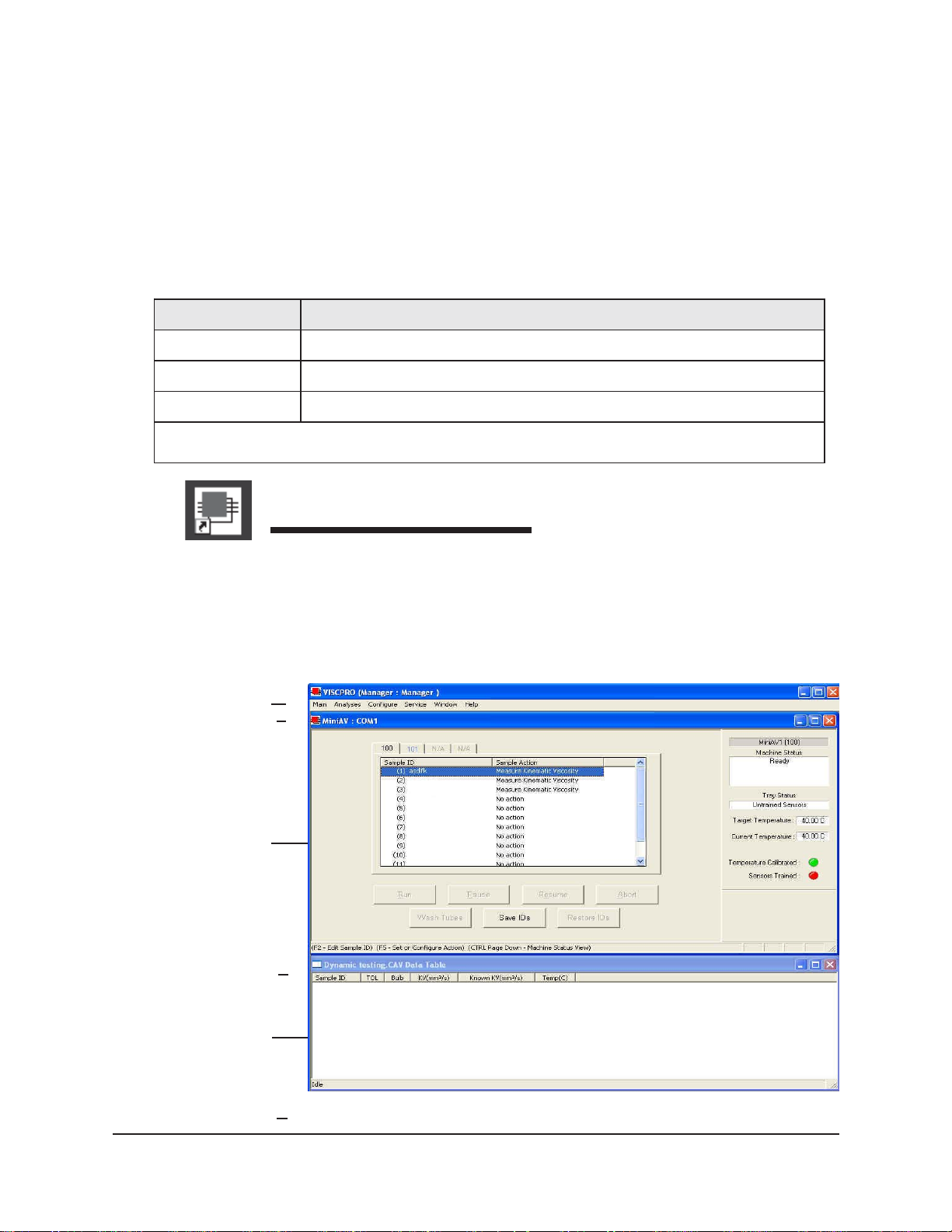
settings. The image below demonstrates a typical screen configuration:
®
The VISCPRO
primary display
®
The VISCPRO
VISCPRO
primary display window is framed on the top by the
®
title bar and menu bar, and on the bottom by the VISCPRO
status bar. The application window can be user -configured to include child
windows (Sample Input or Machine Status windows, Analyses) which can
be opened and closed independently . The Sample Input window describes
your CANNON
®
instrument and provides controls for running tests. The
Analysis window presents data from miniPV Series tests.
®
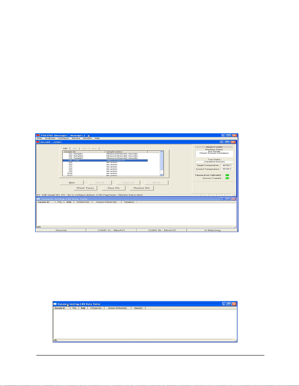
The Sample Input window
NOTE
The Data Table analysis/report window (displays data from completed tests)
CANNON
®
miniPV-Series Automatic Viscometer with VISCPRO® Instruction & Operation Manual
If the Sample Input window does not appear when the software loads, click
View Instrument from the Main menu, then click the desired instrument group
(type of instrument, e.g. miniPV Series, CCS, CAV -2100) from the list of
available instruments and click OK. If the Available Instruments list box is
blank, your miniPV Series instrument may not be on-line. Check cable
connections and make certain the unit power switch is ON.
Version 1.a— January, 2011; CANNON
2139 High Tech Road • State College, PA 16803 • USA
®
Instrument Company
Page 15
Checking configuration
Initial configuration
The installation CD-ROM copy of the SAMPLES.MDB file contains
initial factory calibration data unique to that instrument.NOTE
If you wish to restore the original configuration, archive your sample data
before doing so (see Chapter 13 for information on using the Database
Manager software). Then copy the original SAMPLES.MDB file from the
CD-ROM to the database directory corresponding to your operating system
(see table, previous page).
Follow the procedures in the next several sections of this chapter to
verify/edit the instrument and calibration settings to ensure that they
conform to the actual characteristics of your CANNON
®
instrument.
9
Configuration protection
Logging in
It is not necessary to log in to view current instrument settings. However,
to change the configuration settings, you must log in to the security
system as a manager. The software is installed with a default Manager
account. This account has no password, allowing any operator access to
manager-level software functions as long as the password is not activated/changed. If you would like to engage the full-release security
options, see Security Options in Chapter 4 for instructions.
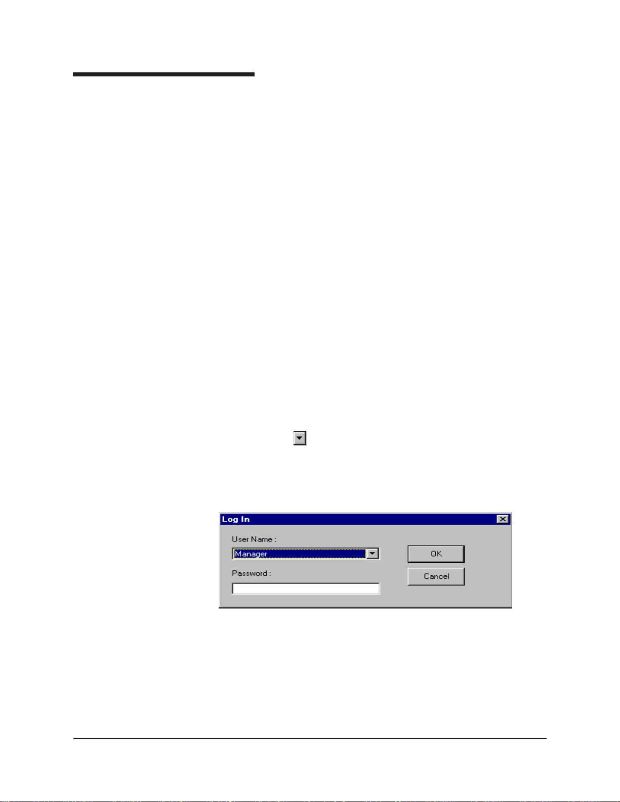
1. Use your mouse to click Main from the VISCPRO® menu bar.
2. Click Log In from the Main menu options.
3. Click on the (arrow) on the right side of the User Name: list box
to display the list of registered users.
4. Click Manager. Do NOT enter a password unless you have previ-
ously set up the Manager account with a password.
5. Click OK. The Log In window will close automatically and you will
be logged in as management personnel.
Checking Instrument Settings
1. Use your mouse to click (select) Configure from the VISCPRO
menu bar.
CANNON
®
miniPV-Series Automatic Viscometer with VISCPRO® Instruction & Operation Manual
Version 1.a— January, 2011; CANNON
2139 High Tech Road • State College, PA 16803 • USA
®
Instrument Company
®
Page 16
10
2. Select your instrument from the list of available instruments (there
may be only one instrument in the list).
3. Select Instrument Settings from the list of configuration options.
The Instrument Settings window will appear .
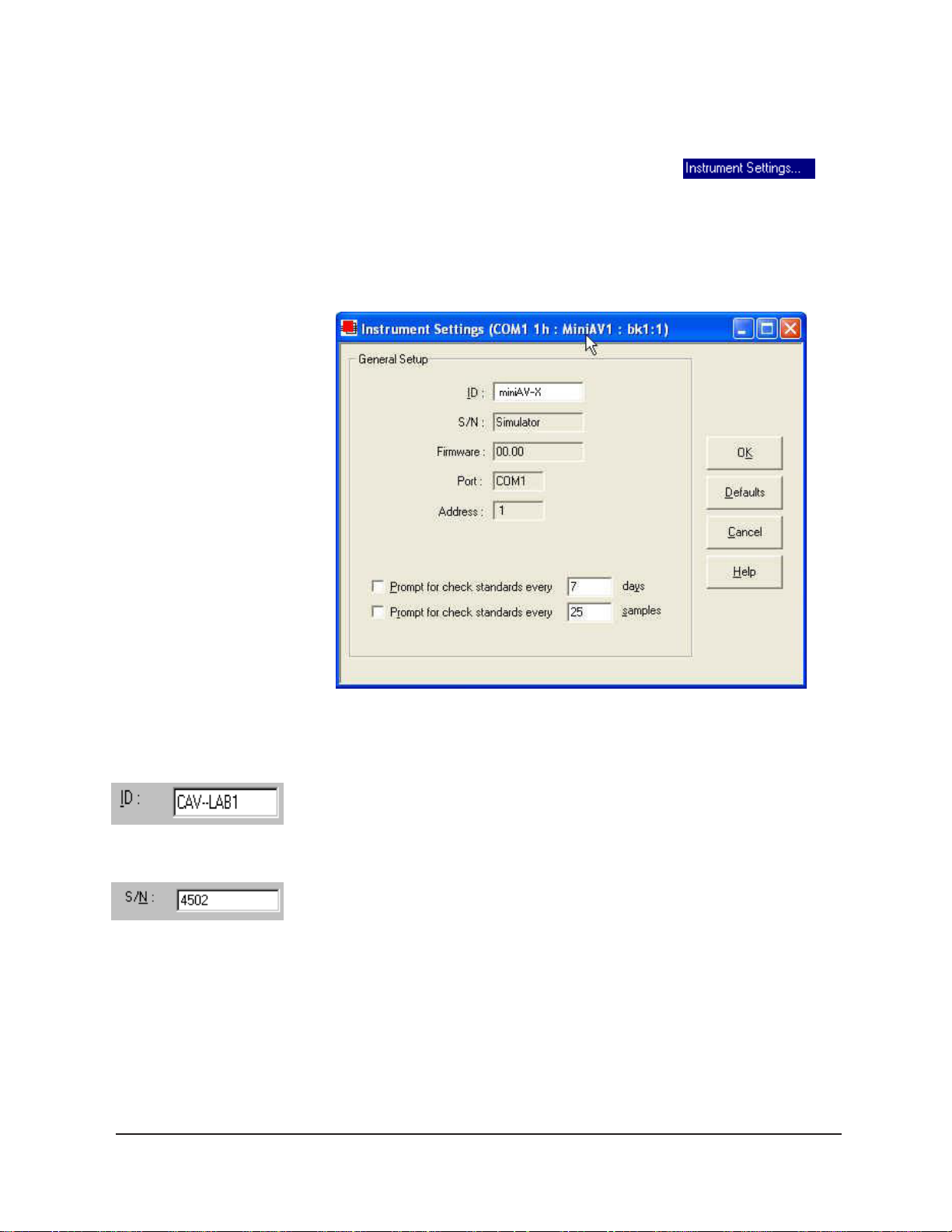
You will use the Instrument Settings window (see below) to describe
and control miniPV Series instrument operational features. These settings
affect the instrument as a whole. Check the instrument settings for your
instrument per the instructions below , and make any necessary changes:
Prompt options
CANNON
The Instrument Settings window
Use the ID field to input instrument identification information using up to
16 alphanumeric characters.
The S/N: field (non-editable) indicates the serial number from the label on
the miniPV Series rear service panel.
The Prompt for Check Standards options permit you to set a computer-
ized “alarm clock” which will pop up a message reminder to run a check
standard based on the schedule you set with the control. Notice that you
can specify a reminder after “x” number of days and/or “x” number of
samples. Click the check box(es) to enable/disable each reminder.
When you have verified all settings, click OK.
®
miniPV-Series Automatic Viscometer with VISCPRO® Instruction & Operation Manual
Version 1.a— January, 2011; CANNON
2139 High Tech Road • State College, PA 16803 • USA
®
Instrument Company
Page 17
Viewing/editing setup information
11
NOTE
For first-time installation, make certain that the factory-prepared Configuration file has been copied to the Default Data directory per instructions on
page 7 of manual. If your instrument has already been configured, you can
use the instructions in this section of the manual to check or, if necessary,
change the instrument settings.
1. Click Configure from the VISCPRO® menu bar.
2. Select your instrument group and instrument from the list of available
instruments.
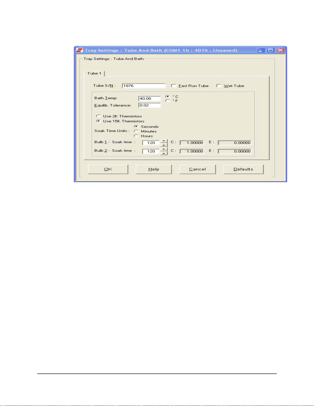
3. Select Tray Settings: T ube and Bath from the list of configuration
options. The T ray Settings: Tube and Bath window will appear.
CANNON
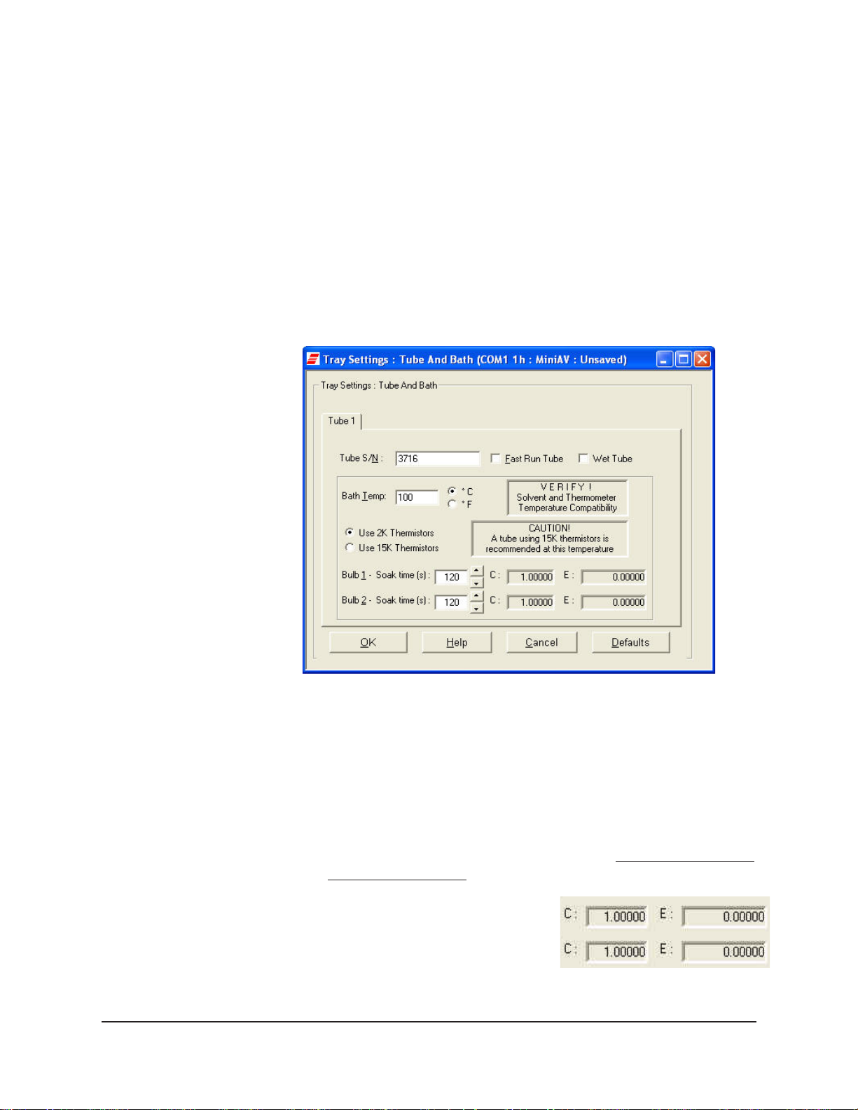
The Tray Settings: Tube and Bath window
The T ray Settings: T ube and Bath window contains setup information
for each tube associated with your instrument. On multiple-tube CANNON instruments, you can click on the tube tabs to see the setup information for different tubes.
4. Verify that the tube serial number ( Tube S/N) is correct. If it is not,
input the correct serial number in the text box.
Each tube should have
a unique serial number!
5. Verify the presence of calibration
values (C and E) for each bulb. If
calibration data is not available, the
default values are C=1 and E=0.
Sample calibration constants
®
miniPV-Series Automatic Viscometer with VISCPRO® Instruction & Operation Manual
Version 1.a— January, 2011; CANNON
2139 High Tech Road • State College, PA 16803 • USA
®
Instrument Company
Page 18
12
Manually changing tube calibration constants
If you discovered any errors in the values of the calibration constants
(see previous section), follow the directions in this section to manually
correct them using calibration information previously obtained for your
unit. If the calibration values are correct, instrument setup is complete.
Procedure
NOTE
This procedure for manually entering/changing calibration constants
bypasses the normal calibration procedure. T o ensure the most accurate
viscosity readings, CANNON® Instrument Company recommends that the
instrument be calibrated per the calibration procedure outlined in Chapter 3.
1. Log in as a Manager and click Configure from the VISCPRO
®
menu bar.
2. Select your instrument from the list of available instruments.
3. Select Calibration from the list of configuration options. The Cali-
bration window will appear (see next page).
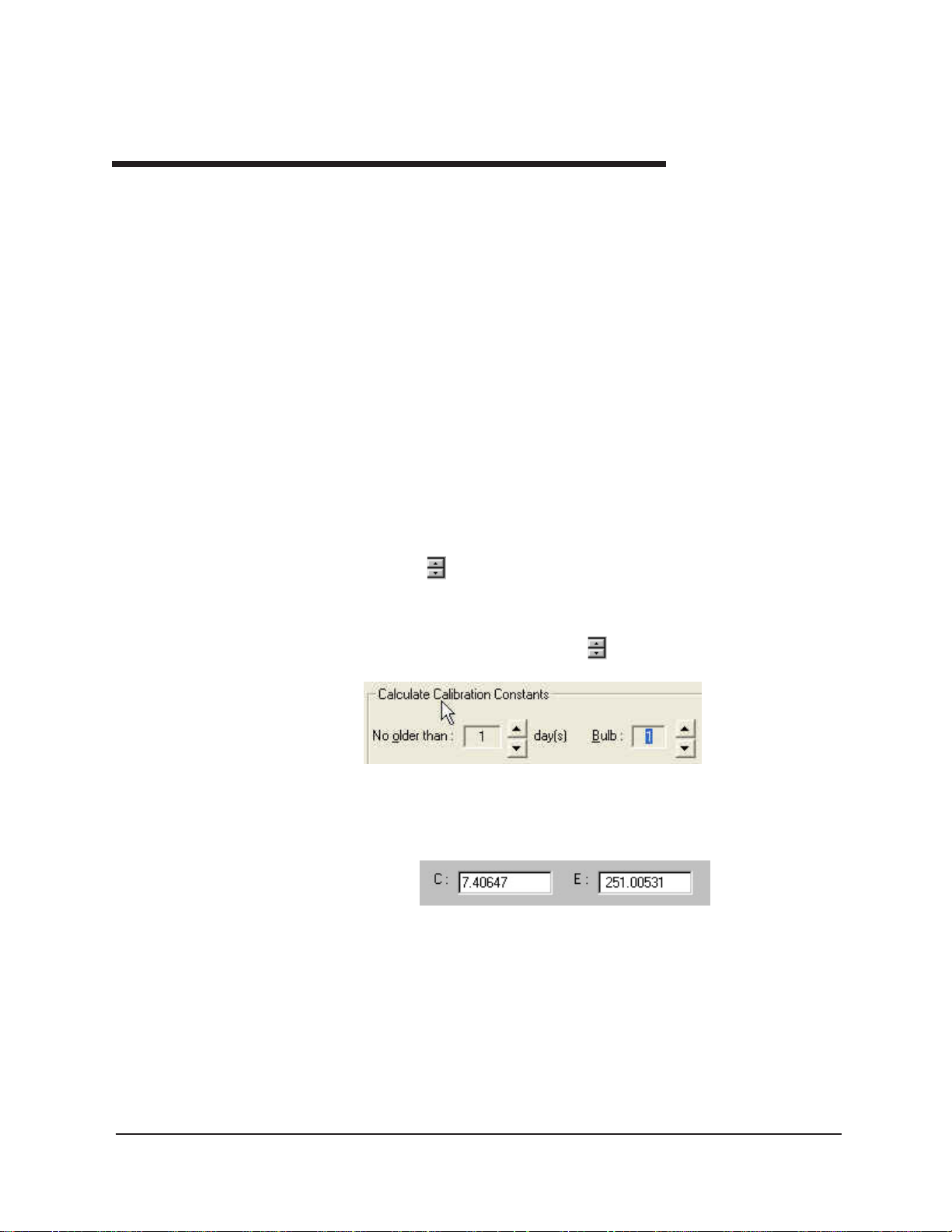
The Calibration window provides controls for calibrating each bulb of
any viscometer associated with your instrument. You can click on the bulb
spin controls
to display current constants and valid check standard
data available for calibration of each bulb.
1. Make sure that the spin controls
for Bulb are set to “1”:
CANNON
This corresponds to the bottom bulb in the tube.
2. Check the values for the calibration constant(s) as they appear at the
bottom of the window:
®
miniPV-Series Automatic Viscometer with VISCPRO® Instruction & Operation Manual
Version 1.a— January, 2011; CANNON
2139 High Tech Road • State College, PA 16803 • USA
®
Instrument Company
Page 19
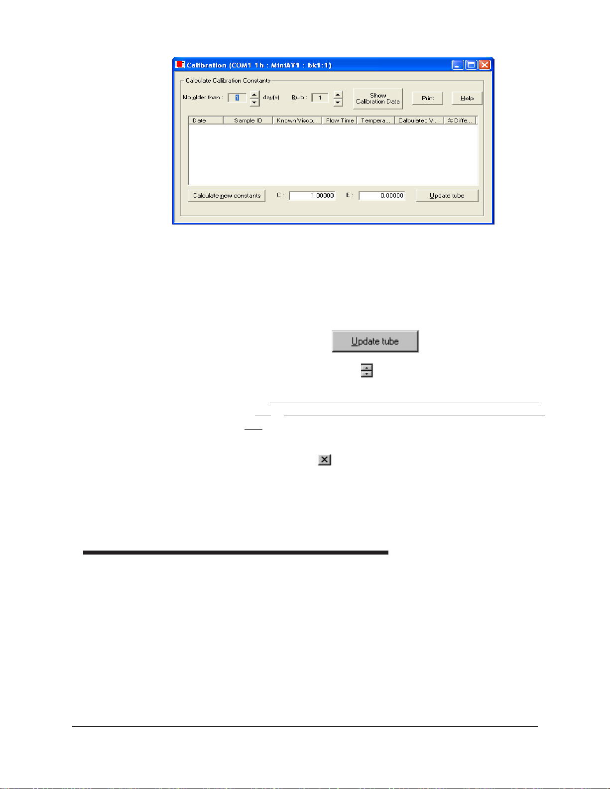
The Calibration window
Compare this value to your archive of the calibration constant data (if
available) for bulb 1. The values should be identical.
3. If they are not, place your cursor in the appropriate field, delete the
entry, then type the correct values for the constant in the text box.
13
4. Click Update tube
5. Use the bulb spin controls
to select the other bulb(s) for which
you noted calibration constant errors. Input the correct values for
Make certain to click Update Tube after you have corrected
each.
C and E calibration values for each bulb BEFORE selecting the next
bulb.
6. When you have entered corrected constant values for each bulb on
both tubes, click
to exit the Calibration window.
You have verified the software configuration of VISCPRO
samples with your instrument, follow the instructions in Chapter 2. For
additional details regarding operating procedures for your instrument or
software, consult the appropriate section of this manual.
Checking Wash and Advanced Settings
T o check Wash Settings for your miniPV Series instrument, click Configure from the VISCPRO menu options and select the desired instrument.
Then click Tray Settings: Wash. The Tray Settings: Wash window
will appear.
.
®
. To test
CANNON
®
miniPV-Series Automatic Viscometer with VISCPRO® Instruction & Operation Manual
Version 1.a— January, 2011; CANNON
2139 High Tech Road • State College, PA 16803 • USA
®
Instrument Company
Page 20
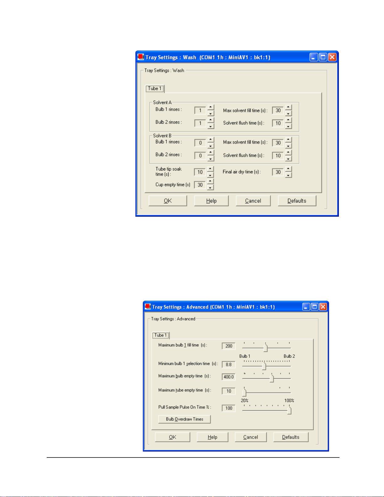
14
Compare the values in the Tray Settings: W ash window with your
archived values and make any necessary changes; then click OK.
T o check Advanced Settings for your miniPV Series instrument, click
Configure from the VISCPRO menu options and select the desired
instrument. Then click Tray Settings: Advanced. The Tray Settings:
Advanced window will appear .
CANNON
®
miniPV-Series Automatic Viscometer with VISCPRO® Instruction & Operation Manual
Version 1.a— January, 2011; CANNON
2139 High Tech Road • State College, PA 16803 • USA
®
Instrument Company
Page 21
Compare the values in the Tray Settings: Advanced window with your
archived values and make any necessary changes; then click OK.
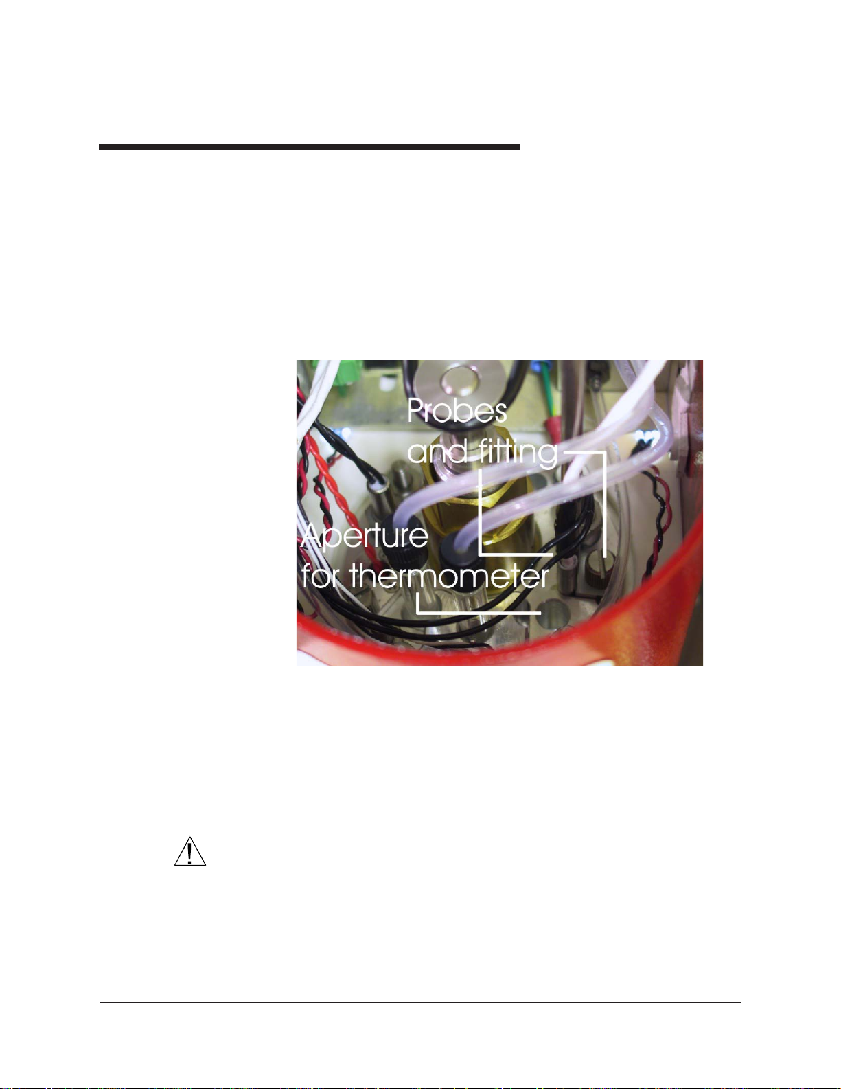
Preparing the miniPV Series for testing
Inserting the miniPV Series temperature probes/reference thermometer
15
Inserting the probes
miniPV Series top bath flange
The temperature probe and thermal fuse probe are semi-permanently
installed. Initial installation or replacement requires removal of the top
cover of the bath unit. The probes are inserted through the narrow
aperture on the top bath flange and held in place with a sliding metal plate
(friction fitting) secured with a thumbscrew .
Inserting the thermometer
CAUTION
CANNON
®
miniPV-Series Automatic Viscometer with VISCPRO® Instruction & Operation Manual
Version 1.a— January, 2011; CANNON
The ASTM reference thermometer/adapter assembly can be inserted
through the grommet in the bath top cover and through the larger circular
aperture on the top bath flange (see photo image above). The assembly
includes a stop collar with set screw that can be adjusted to vary the
thermometer height.
Do NOT insert a reference thermometer while the miniPV Series bath
impeller is operating, as damage to the thermometer and/or viscometer
tube may result. Make certain to insert the appropriate reference thermometer for the current bath temperature! Use appropriate safety procedures
when handling the thermometer, as it contains mercury .
®
Instrument Company
2139 High Tech Road • State College, PA 16803 • USA
Page 22
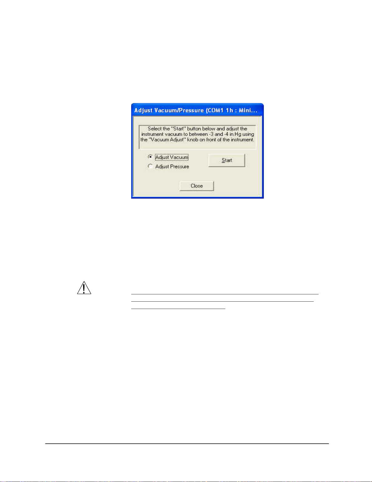
16
Adjusting Vacuum/Pressure settings
T o adjust the vacuum setting for the miniPV Series, click Service from
the VISCPRO menu options and select the desired instrument group and
instrument. Then click Adjust Vacuum/Pressure to open the Adjust
Vacuum/Pressure window.
Select the desired adjustment (vacuum or pressure) and then follow the
screen prompts to complete the adjustment procedure, using the appropriate controls on the instrument side (“ear”) panel. The prompts will display
recommended vacuum/pressure settings and will also indicate how
adjustments may be made to alter the settings.
Setting bath temperature
WARNING
Prior to setting the bath temperature, ensure that the reference thermometer in the bath is suitable for the desired temperature range. If not,
remove thermometer from the bath. If the bath temperature rises above
the range of the thermometer, it may be damaged. Mercury thermo-meters
pose particular problems, since mercury from a damaged thermo-meter
may circulate with bath fluid.
To set the temperature:
1. Load the VISCPRO® software and click Configuration.
2. Select the miniPV Series from the list of available instruments and
click T ray Settings: T ube and Bath.
CANNON
®
miniPV-Series Automatic Viscometer with VISCPRO® Instruction & Operation Manual
Version 1.a— January, 2011; CANNON
2139 High Tech Road • State College, PA 16803 • USA
®
Instrument Company
Page 23
17
3. Select the desired unit of temperature measurement (°C or °F).
4. Type the desired temperature in the Bath Temp: field. Acceptable
NOTES
The miniPV Series will not allow sample testing until the instrument has
equilibrated temperature at the test temperature.
T o cancel temperature selection before completing the procedure, click
Cancel.
After the target temperature has been set, the miniPV Series bath
temperature will be adjusted to the target temperature and the bath will
equilibrate at the test temperature. The VISCPRO II software always
displays the current and target bath temperature in the Sample Input
window.
Checking wash functions
T o ensure function of the solvent wash system, follow the procedure
below:
1. Place an empty vial in the sample tray position 1.
values are any numbers between 20°C and 100°C. If necessary, you
may use the decimal point key to input temperature to the nearest
0.01°C. Press OK to save the temperature setting.
CANNON
2. Select Wash viscometer tube to open the Wash viscometer tube
window .
®
miniPV-Series Automatic Viscometer with VISCPRO® Instruction & Operation Manual
Version 1.a— January, 2011; CANNON
2139 High Tech Road • State College, PA 16803 • USA
®
Instrument Company
Page 24

18
3. Click Begin Wash to initiate the wash cycle. The Status: indicator
will display and update current actions.
Bypass .... option
NOTES
Training tube sensors
NOTES
CAUTION
T o begin washing an evacuated sample cup, click the option box to make
certain that the Bypass initial cup evacuation option is selected. Do not
use this option with a filled cup or the cup will overflow.
4. When the Wash cycle has been completed, click Done to exit the
Wash viscometer tube window.
The Wash operation cannot be executed if the tube is currently running a
sample. To terminate the Wash cycle at any time, click Abort W ash.
The Wash viscometer tube function overrides automatic miniPV Series
software operations. Verify that the tubes are clean and dry before initiating computer-controlled sample testing.
miniPV Series tube sensors must be trained in order for the instrument to
properly perform test functions. To train miniPV Series sensors, follow
the instructions in Chapter 3.
The temperature should be calibrated prior to training the miniPV Series
tube sensors.
Calibrating the miniPV Series
Notes on computer-directed miniPV Series operation
Reporting data
CANNON
To ensure accurate test results, your instrument may need to be calibrated. If necessary , follow the instructions in Chapter 3 to calibrate your
miniPV Series temperature probe and viscometer tube.
A computer is required for miniPV Series operation. The computer
provides for automatic control of miniPV Series functions using the
VISCPRO® controlling software. Computer control permits data entry of
up to ten different sample IDs. Each of the identified samples can then be
tested with the miniPV Series instrument.
Test data for the samples is automatically saved to the VISCPRO
database for future reporting/data collection. Additionally , several reports
(analyses) may be used to calculate and display kinematic viscosity and
viscosity index (VI) values. See the chapters on VISCPRO® analyses for
further information.
All analyses provide a dynamic reporting option which can dynamically
display and transmit test results as testing is completed. Data can be sent
to your computer screen, printer, and/or serial port for in-house data
collection. See Chapter 6 for more information on configuring analyses.
®
miniPV®-HX Automatic Viscometer with VISCPRO® Instruction & Operation Manual
Version 1.0— January , 2011; CANNON
2139 High Tech Road • State College, PA 16803 • USA
®
Instrument Company
®
Page 25

CHAPTER
19
2
Turning on the miniPV Series
Testing samples
Loading software
TESTING SAMPLES WITH THE
miniPV Series
This chapter of the manual will provide information on testing samples
using the miniPV Series. Observe the safety cautions noted in the
introductory chapter when operating equipment. The miniPV Series
should only be operated by qualified personnel.
Turn on the miniPV Series Bath Unit using the power switch on the
power supply unit.
1. Turn on the computer and load the miniPV Series software by
double-clicking the VISCPRO
®
II icon on the Desktop.
NOTES
NOTES
If the software is already loaded, use your computer mouse to click Main
from the menu bar and click Poll for Instruments from the Main menu
options. This will establish communications between the computer and the
on-line instrument.
Permit the bath to stabilize at test temperature before testing samples.
2. Pour sample material into the glass vial(s). For 20 mL vials, fill only
half full, as the viscometer tube will displace sample in the vial.
Approximately 10 mL of sample should be sufficient for testing in
either bulb of the viscometer.
Do not overfill the vials. Sample overflow may create problems for the tube
cleaning cycle.
You should periodically test calibration check st andards per your estab-
lished laboratory procedures. Recalibrate the miniPV Series (see
Chapter 3, Calibration) if result variance warrants.
3. Place the sample vials in the carousel.
4 Check the thermometer in the temperature bath to
make sure the bath is holding the proper temperature. If necessary, calibrate the miniPV Series
temperature control probe using the temperature
calibration procedure in Chapter 3.
CANNON
Filled
®
miniAV®-HX Automatic Viscometer with VISCPRO® Instruction & Operation Manual
Version 1.0— January, 2011; CANNON
2139 High Tech Road • State College, PA 16803 • USA
®
Instrument Company
Page 26
20
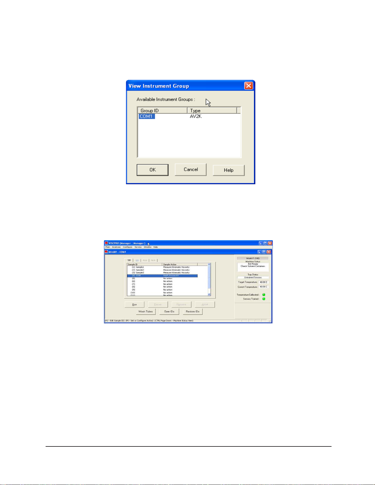
5. Open the View Instrument Group window (if it is not already open)
by clicking View Instrument from the Main menu and selecting the
desired instrument group from the list box (see Chapter 4 for more
information).
The View Instrument Group window
6. Select the desired group ID and click OK to display the Sample
Input View .
The Samle Input window (miniPV Series four--bath system)
Then click the Tray tab corresponding with the desired miniPV Series.
7. Double-click on Sample ID (1) with the left mouse button to access
the sample ID data entry field (or press 2).
8. Enter sample ID information in the sample list box using your computer keyboard. After you have typed the sample ID, press the T
key to complete the entry and move the cursor to the next Sample ID
field. Or press R to complete the entry.
NOTE
CANNON
Once sample information is entered, the software automatically assigns a
sample action, Measure Sample Viscosity, for the sample. If you do not
®
miniPV®-HX Automatic Viscometer with VISCPRO® Instruction & Operation Manual
Version 1.0— January , 2011; CANNON
2139 High Tech Road • State College, PA 16803 • USA
®
Instrument Company
Page 27

enter a sample ID, the sample is automatically labeled Unknown.
T o select or change a sample action, highlight the appropriate Sample
ID(s) using the mouse or arrow keys, then click the RIGHT mouse button
to access sample action options:
No action
Determine Solution Relative V iscosity
Determine Blank (Solvent) V iscosity
Determine Solvent V iscosity
Verify Known RV
Measure Kinematic Viscosity
Verify Known KV
No action: If No action is selected, all information for that sample
position will be cleared and that carousel position will not be tested.
Determine Solution RV If Determine Solution Relative Viscosity is
selected as the test option for a sample, the Polymer Sample Measurement Options window will open, permitting data entry of relevant parameters for the determination of RV. For information on data entry options,
21
Determine Solvent Viscosity If Determine Solvent Viscosity is selected as the test option for a sample, the Polymer Sample Measurement
Options window will open,
Verify Known KV/RV If Verify Known RV (relative viscosity) or Verify
Known KV (kinematic viscosity) are selected as the test option for a
sample, the Polymer Sample Measurement Options window will include a
new data entry field, RV or Check Standard Viscosity, which permits the
user to enter the known RV or KV of the sample: This information will
permit the VISCPRO software to compare calculated RV or KV values
with known values to determine the accuracy of current calibration and
machine performance. Measure Kinematic Viscosity If Measure Kinematic Viscosity is selected as the test option for a sample, the VISCPRO
software will calculate kinematic viscosity for the sample using the
sample drop time and ASTM D 445 formulas.
Defining and using a solvent blank for RV analysis
Using a solvent blank Relative viscosity by definition is a ratio between
the absolute viscosity* of a solution containing a solvent and sample
material, and the absolute viscosity* of the pure solvent . VISCPRO
calculates this ratio by comparing sample drop times for the solution and
the solvent “blank”. The significance of the resultant value is enhanced as
two additional variables are taken into account—sample/solvent density
and (with drop times under 200 seconds) an empirically-determined
kinetic energy correction constant.
CANNON
®
miniPV-Series Automatic Viscometer with VISCPRO® Instruction & Operation Manual
Version 1.a— January, 2011; CANNON
2139 High Tech Road • State College, PA 16803 • USA
®
Instrument Company
Page 28

22
*The term absolute viscosity , as used in this manual, is also known as
dynamic viscosity . For the purpose of VISCPRO® software viscosity
calculations, and per ASTM D 2857 specifications, the absolute viscosity
is defined by the equation ç = Ctñ - Eñ/t 2 where C is a constant, t is the
drop time, ñ is the solution or solvent density and E is the kinetic energy
correction constant.
Relative viscosity calculation
The relative viscosity (RV) ratio (solute to solvent blank) is therefore defined
by the equation:
Software selection of blank
Since determination of a relative viscosity involves a comparison of solution
and blank, the VISCPRO controlling software requires the identification of a
blank for any samples tested using the Determine Solution Relative Viscosity
sample action. The blank is ordinarily selected from a list of solvents maintained by the VISCPRO database. This list is accessible from the Polymer
Measurement Sample Options window by using the drop-down list feature:
To display the list, click on the arrow. If the correct blank has not yet been
defined, the user may create a new blank by typing an ID for the blank into the
open field in the Polymer Measurement Sample Options window:
Procedure for blank definition
New blanks are created by testing the solvent in the miniPV using the
Determine Solvent V iscosity sample action. Follow the procedure for
testing samples
1. Select Determine Solvent Viscosity as the sample action for the
desired sample.
2. Enter an ID for each blank that includes both a description of the
blank and also the temperature at which that blank is to be tested in
the miniPV. The blank must be tested at the same temperature
intended for the solution
NOTE
CANNON
In some MiniPV applications involving dilute solutions, it may not be
necessary to input the density for the solvent blank and/or solution. If you
choose not to input solvent density for either the blank or for the sample,
®
miniPV-Series Automatic Viscometer with VISCPRO® Instruction & Operation Manual
Version 1.a— January, 2011; CANNON
2139 High Tech Road • State College, PA 16803 • USA
®
Instrument Company
Page 29

the density of both will not be included in relative viscosity calculations.
Unity Reference blank
A preexistent blank, Unity Reference, is hard-coded in the VISCPRO®
software with a value of “1”. Users selecting this blank when running an
RV
sample are effectively calculating the kinematic viscosity of the solution in
a
manner which permits them to use VISCPRO® polymer report options.
Testing volatile samples
The environment for viscosity measurement using the MiniPV
AIRBATH and compound viscometer is much different than it would be
with a conventional liquid bath and a U-shaped viscometer. Because of
the continuous downward flow of air in the AIRBATH, evaporation of
23
NOTES
sample components have the potential to adversely affect the analysis.
This
is because evaporation changes the composition of the sample and may
also affect temperature stability).
If you are testing at higher temperatures and/or with samples containing
components which may evaporate during the analysis, cover the sample
with aluminum foil or other easily penetrable membrane and secure with
the “O” ring and cap supplied for that purpose with the MiniPV. This
will seal the sample until the viscosity measurement is performed. Then
the
viscometer tip penetrates the aluminum foil/membrane and performs the
entire analysis without withdrawing completely from the sample vial.
If the aluminum foil has been penetrated and the sample has remained
in the analysis chamber for more than a few minutes, do not attempt to
reuse the sample. A new sample should be prepared.
CANNON
It is especially important to cover the samples when performing solution
viscosity analysis of polymers. Even a slight change of composition
caused by solvent evaporation may cause significant error.
Even samples that are high in viscosity may still contain volatile compo-
nents;
®
miniPV-Series Automatic Viscometer with VISCPRO® Instruction & Operation Manual
Version 1.a— January, 2011; CANNON
2139 High Tech Road • State College, PA 16803 • USA
®
Instrument Company
Page 30

24
these samples should also be covered before analysis. Most lubricating
oils, because they are manufactured at high temperatures and low pressures, do not contain significant volatile components and can be analyzed
without being covered.
The PolyVISC SPS Solution Preparation System from Cannon Instrument
Company is a semi-automated solution preparation system that can be
used with the minPV instruments. Contact Cannon for more information.
NOTE
Running check standards
NOTE
For additional information on software data entry features, including
multiple sample selection and cut & paste options, see Testing samples—
software options in Chapter 4.
If Verify Known KV is selected as the test option for a sample, the
Viscosity Action window will open automatically. Enter the neces-
sary check standard data, including the Check St andard viscosity
from the standard bottle, and click OK to complete data entry. To
revise or confirm standard data, right-click on the desired sample ID
from the list box and select Configure from the popup menu choices.
See Chapter 4 for additional information on the Viscosity Action window .
9. Continue entering sample information for all desired trays. When
sample ID data entry is complete, check the Tray Status window to
verify that all trays are ready for testing.
10. Click on the RUN button at the bottom of the Sample Input window.
The Select Trays window will open if more than one miniPV Series
instrument is online.
11. If necessary, click on the check box(es) to select the desired prepared “tray” (sample sequence) for automatic testing. For the
miniPV Series, a tray corresponds to the miniPV Series instrument.
Then click OK to begin the miniPV Series test(s).
Pausing a test
NOTE
Resuming a test
CANNON
®
miniPV-Series Automatic Viscometer with VISCPRO® Instruction & Operation Manual
T o temporarily halt testing for a given tube/sample, click the Pause
button from the Sample Input window. Then select the desired tray
(miniPV Series instrument) and pause action(s) from the Select Trays
window (Pause Now will immediately pause test actions; Pause after
current sample will pause testing after the current test is complete).
Click OK to pause testing for the selected tray(s).
If the test was paused prior to the initiation of the Wash cycle, drop time
data for that sample will be discarded.
To resume test actions for paused trays, click the Resume button from
the Sample Input window. Then select the desired trays from the Select
Trays window. Click OK to resume sample testing (see note above).
Version 1.a— January, 2011; CANNON
2139 High Tech Road • State College, PA 16803 • USA
®
Instrument Company
Page 31

Aborting a test
25
T o permanently halt testing for a given tube/tray , click the Abort button
from the Sample Input window. Then select the desired trays from the
Select Trays window. Click OK to abort testing for the selected tray.
NOTE
Concluding a test
CAUTION
Aborting a test clears all sample test information for that tray . If test
actions are aborted, it is the responsibility of the user to restore the
instrument to a safe state before running tests (see Service menu options
in chapter 4 for more information on tube washing and drying).
After automatic testing has been completed, make certain that:
1. the sample vial carrier is in the lowered position.
Use appropriate procedures when handling warm sample vials to avoid the
possibility of burns.
2. the Machine Status (as indicated in the VISCPRO® Sample Input
Machine Status window), is READY, and
3. the Tray Status for the tube, as indicated in the VISCPRO
®
Sample
Input T ray S tatus window , is IDLE. Kinematic viscosity for any
tested samples will be displayed in the Sample Action column in the
action list for the selected tube.
NOTE
To review status of other online instruments, click the tube tab corresponding to the desired instrument (see next section).
If necessary, wipe any excess oil from the base of the miniPV Series,
sample vial and vial holder using an absorbent paper towel. If necessary ,
clean these components before reuse by wiping with a paper towel
wetted with appropriate solvent.
Working with Instrument Groups
VISCPRO II provides a convenient interface for working with multiple
CANNON instruments simultaneously . Rather than requiring the user to
open individual Instrument V iews for each online instrument, the Sample
Input window (formerly the Instrument View window in VISCPRO)
provides individual tabs for each viscometer tube, making it easy to enter
sample information for up to four different instruments. The Machine
Status window makes it possible to monitor the performance of all
instruments in an Instrument Group simultaneously .
CANNON
®
miniPV-Series Automatic Viscometer with VISCPRO® Instruction & Operation Manual
Version 1.a— January, 2011; CANNON
2139 High Tech Road • State College, PA 16803 • USA
®
Instrument Company
Page 32

26
Here’s how it works: Just click Main/V iew Instrument from the
VISCPRO II interface to open the View Instrument Group window,
which displays all CANNON instrument types communicating with your
computer. Then select the desired instrument group (all instruments in a
single group communicate with the computer via the same COM port).
Once you have opened the desired instrument group, the Sample Input
window will appear. Individual TABBED PAGES now make it possible to
enter sample information for any viscometer in the instrument group.
The Machine Status window
You can toggle back and forth between the Sample Input window and
the new instrument group Machine Status window by pressing Ctrl-Page Down.
Monitoring instrument status
You can monitor the status of all instruments in an instrument group by
pressing Ctrl-Page Down from the Sample Input window to display the
Machine Status window. To return to the Sample Input window, press
Ctrl-Page Down again.In the image above, instruments three and four
do not exist but could be accommodated in this instrument group. The
“placeholders” for these instruments are greyed out to indicate that
additional machines are not yet online for the group.
If additional instruments are online but are not appearing in the correct
instrument group, check network connections and make certain that each
instrument is turned on and functioning normally . Then click Main/Poll for
Instruments to refresh communication with online instruments.
Group configuration
If your laboratory had 3 miniPV Series instruments with RS-485 connections, all could communicate with the computer via a single COM port,
provided that they were all assigned different instrument addresses. Each
instrument group provides its own Instrument V iew customized for that
CANNON
®
miniPV-Series Automatic Viscometer with VISCPRO® Instruction & Operation Manual
Version 1.a— January, 2011; CANNON
2139 High Tech Road • State College, PA 16803 • USA
®
Instrument Company
Page 33

instrument type. The number of instruments that can be assigned per
group varies per instrument type. The Cold-Cranking Simulator (CCS)
design allows only one instrument per group for that instrument type.
When a new type of instrument is found on a port, the VISCPRO
software automatically creates a group for that instrument. The maximum number of instruments that can exist on that port is determined by
the nature of the instrument. A single COM port may be used for
communication with multiple instrument TYPES as long as the total
number of instruments associated with the port does not exceed the
maximum number of instruments capable of being displayed in the group
that can contain the least number of instruments (usually four).
Configuring the Machine Status window to correspond with multiple-instrument
placement
It is desirable to configure your miniPV Series instruments so that the
VISCPRO software computer interface display for the instrument group
(Machine St atus window) corresponds with the actual physical placement of the multiple instruments in the laboratory .
Use a screwdriver to adjust the arrow on the instrument address dial
(inside the miniPV Series left wing panel) to assign each instrument in the
group a unique address using numbers 1-4 from left to right. NOTE
Do not use “0” or “9” as an instrument address for this configuration
option.
27
When configured per the above instructions, the instruments will always
be displayed in the same “sequence” in the Machine Status window
even if a single instrument in the series is not online.
Viewing test results
Data obtained from all miniPV Series instruments during sample testing is
promptly displayed in the Sample Input window (Sample Action
column). It is also stored in the central VISCPRO® database. To view
historical data, you must create an analysis requesting the desired sample
information.
The following analyses are shipped with the software:
CA V Data T able—displays test information of your choosing.
Error Log Table–lists error messages and related data.
Standard VI Table—provides a report of matched samples according
Error Data, Sample Data and VI Data Export Analyses–config-
Creating an analysis
to configuration information you provide.
ures data for output to a file, parallel port, or serial port.
CANNON
®
miniPV-Series Automatic Viscometer with VISCPRO® Instruction & Operation Manual
Version 1.a— January, 2011; CANNON
2139 High Tech Road • State College, PA 16803 • USA
®
Instrument Company
Page 34

28
The following procedure creates a standard CAV Data Table which will
be updated as samples are tested. For additional information on analyses,
consult the manual chapter corresponding to the desired analysis.
1. Select Analyses from the VISCPRO
®
primary menu options.
2. Select View Analysis ... from the Analyses menu. The Choose
Analysis window will appear.
3. Double-click on Basic Package.
4. Click on CAV Data Table to reveal the available analyses.
5. Click on the Define and Open New Configuration radio button
(or verify that the option is selected).
6. Click OK. The Sample Analysis Configuration window will
appear. The Sample Analysis Configuration window consists of
tabbed pages with filter options appropriate for the analysis.
7. Click on Date Filter and then click the Use Dynamic Update check
box. This option will update the displayed analysis with new data as
samples are tested.
NOTE
For additional information on analysis filter options, consult the manual
chapter corresponding to the desired analysis.
8. Click on the spin controls to select a value for the sample time
window (the time parameter you desire for the report of recent test
data).
9. Configure any other report options (see Chapter 7 for details). Then
click OK. The program will prompt you to save the analysis configuration.
10. Click Yes. (OR click NO to display the analysis without saving it.)
11. If Yes was selected, use your keyboard to type the name you wish to
use for the analysis in the text box.
12. Click OK. The analysis will be saved and data obtained during the
selected time window will be displayed.
Configuring the VI Matcher (optional)
VI Matching with VISCPRO
®
The VI Matcher is a VISCPRO® software feature that functions in
tandem with the VI analyses to enable Viscosity Index (VI) calculation
from sample data residing in the VISCPRO® database. To configure the
VI Matcher, see Configuring the VI Matcher in Chapter 4.
CANNON
®
miniPV®-HX Automatic Viscometer with VISCPRO® Instruction & Operation Manual
Version 1.0— January , 2011; CANNON
2139 High Tech Road • State College, PA 16803 • USA
®
Instrument Company
Page 35

CHAPTER
29
3
CALIBRATING THE miniPV Series
Calibration is essential for the proper operation of the miniPV Series. The
miniPV Series is calibrated before it is shipped to the customer . It should
be calibrated again after installation. Frequency of recalibration is at the
discretion of the user. There are two types of calibrations—the temperature calibration ensures that the temperature probe readings conform to
the reference thermometer, and the standard calibration ensures that the
mathematical constants used in calculation of kinematic viscosity from
sample flow times accurately reflect the unique properties of the viscometer tube. The temperature calibration should be performed first.
Calibrating temperature
Periodically , the temperature display of the miniPV Series Bath Unit
should be verified using a reference thermometer for that temperature.
The miniPV Series temperature control system permits the calibration of
the bath temperature to agree with any temperature reference standard,
including an ASTM thermometer mounted within the bath. The bath can
be calibrated by the user whenever the bath temperature is stable for any
given target temperature in degrees Celsius or Fahrenheit.
NOTE
The calibration data is stored in the VISCPRO II software database.
It is important to remember when moving the minAV-X from One PC to
another, the samples.mdb file should also be copied to the new PC to
keep from having to recalibrate the instrument. After calibrating the
temperature (or changing any configuration setting) the user should save
the instrument and tray settings- Save Instrument and Tray Settings under
the Configure menu. [This will insure that the proper settings will be
available if something happens, such as the serial port is changed.]
Calibration procedure
NOTE Depending on security level settings, it may be necessary for you to log in
as a manager to complete the calibration.
1. Set the bath to the desired calibration temperature and make certain
the reference thermometer temperature has stabilized.
2. Click Service/Temperature Calibration for the desired instrument.
CANNON
®
miniAV®-HX Automatic Viscometer with VISCPRO® Instruction & Operation Manual
Version 1.0— January, 2011; CANNON
2139 High Tech Road • State College, PA 16803 • USA
®
Instrument Company
Page 36

30
3. To calibrate temperature, enter the current temperature reading to the
nearest 0.01°C into the Temperature: field, subject to the following:
A decimal point MAY be included as an entry. It should be preceded
by at least two numbers or a "0".
The entered actual temperature must not cause a correction in
temperature greater than +/- 5.0 degrees.
Data entry errors
General/Current Offsets
Training sensors
Multiple or successive entries of correction for any temperature are
permissible. A newly entered corrected temperature is mathematically
compensated with the previously entered correction and is stored in
memory by the onboard microprocessor as the latest correction.
The miniPV Series will not accept temperature reference data outside the
parameters noted previously. If the amount of the correction (delta to
displayed temperature) is too large, the correction will not be accepted.
The General Bath Offset is factory-preset value affecting temperature
control at all temperatures and should not ordinarily be changed. The
Current Offset is the temperature adjustment applied to a particular
temperature to conform bath temperature control to your temperature
reference . Always click the radio button for the Apply As Current
Option when calibrating for a specific temperature.
It is necessary to train instrument sensors in preparation for sample
testing at a specific temperature. The training procedure establishes the
proper power levels for sensor detection of the sample meniscus. The
sensor training data is then stored by the miniPV Series instrument, and
recalled when testing at that temperature. The sensor training procedure
requires approximately 30 minutes (longer at lower temperatures).
NOTE
CANNON
You will be prompted to train sensors by the instrument hardware or
software whenever a new temperature is selected for miniPV Series
operation. Y ou will be unable to test samples until the training has been
®
miniPV-Series Automatic Viscometer with VISCPRO® Instruction & Operation Manual
Version 1.a— January, 2011; CANNON
2139 High Tech Road • State College, PA 16803 • USA
®
Instrument Company
Page 37

completed. Sensor training data remains valid until the sensors are
retrained at the same temperature. Retraining is necessary only when the
viscometer tube is changed, or if sensor performance changes over time.
31
Train Tube Sensors
T o train tube sensors, click Service menu and select the Train T ube
Sensors menu for the desired instrument. The Train Tube Sensors
window will open.
Prewash option: Click the Prewash option if the tube is not clean and
dry . VISCPRO will initiate a cleaning cycle using current wash configuration settings prior to initiating the sensor training procedure.
Trip Points Only option: Click the Trip Point s Only option to adjust
the sensor trip points without setting the voltages. This is useful if it is
neccessary to adjust trip points on sensors for which voltages have
already been set.
After selecting the desired training options click START and follow the
software prompts to complete the sensor training.
Standard tube calibration
During standard calibration, the software uses check standard data
obtained from miniPV Series tests to perform the mathematical calculations necessary to derive new constants for each timing bulb of the
viscometer tube. Then the VISCPRO software displays the new constants and computes a viscosity (in cSt) for each sample using the actual
flow time of the check standards. The resulting viscosity calculation is
compared with the known viscosity of the standard; absolute and comparative data is displayed on the computer screen.
CANNON
®
miniPV-Series Automatic Viscometer with VISCPRO® Instruction & Operation Manual
Version 1.a— January, 2011; CANNON
2139 High Tech Road • State College, PA 16803 • USA
®
Instrument Company
Page 38

32
NOTES
Calibration procedure
The software allows the operator to manually change the constants if necessary to more closely match the known viscosities of the standards.
A separate calibration must be performed for each temperature at which
samples will be tested.
1. Assemble a group of CANNON® standard oils with known kinematic viscosities for calibration. Use at least two different standards
for each bulb. Refer to the following table when choosing the appropriate standards.
elbaTnoitceleSliOnoitarbilaC
1BLUBGNIMIT
)1-2srotsimreht(
timiltScrewolx001-01timiltScrewolx01-1
2. Complete sample ID data entry for each standard.
3. After entering each sample ID, click on the highlighted ID entry using
the RIGHT mouse button (or press 5). Then select Verify Known
KV from the popup window. The Viscosity Action window will
appear.
2BLUBGNIMIT
)1-3srotsimreht(
NOTE
4. Enter the viscosity (in centistokes) for each sample from the standard
bottle, along with other desired configuration settings; then click OK .
If a check standard viscosity has NOT been entered (or if the default
viscosity value of 1.000 has not been accepted by the user), a yellow arrow
(current sample) or red circle caution symbol will appear to the left of the
sample ID:
CANNON
®
miniPV-Series Automatic Viscometer with VISCPRO® Instruction & Operation Manual
Version 1.a— January, 2011; CANNON
2139 High Tech Road • State College, PA 16803 • USA
®
Instrument Company
Page 39

33
CAUTION
Make certain to enter the correct check standard viscosity (in centistokes)
BEFORE running the standards. Incorrect data entry may skew future
calibration results.
5. Click Run, then select the appropriate sample trays to test the
standards.
6. When testing is completed, use the VISCPRO
®
software to log on as
a Manager (Main/Log In) in order to access the calibration menu.
7. Select the desired miniPV Series instrument from the Configure
menu; then select Calibration.
The Calibration window will open.
8. Select the date range for acceptable calibration data by using the No
older than [x] days spin controls
to set the date search param-
eters (if “1” is selected, only data from the standards run in the last
24 hours will be listed). Any check standards from the time frame
you specified which are appropriate for calibration calculations will
appear in the window list box.
CANNON
The miniPV Series Calibration window
9. Use the spin controls
®
miniPV-Series Automatic Viscometer with VISCPRO® Instruction & Operation Manual
Version 1.a— January, 2011; CANNON
2139 High Tech Road • State College, PA 16803 • USA
to select the desired Bulb for calibration.
®
Instrument Company
Page 40

34
Selecting samples
NOTE
Comparing current/new data
10. Select (or deselect) the specific sample entries you desire to use for
calibration from the displayed list by clicking on them. T o select a
range of samples, highlight the first sample and click on the last
sample while simultaneously pressing the S key . T o select
several individual samples for calculation, hold down the C key and
click on each of the desired samples.
You must select at least two entries or the sof tware will not recalculate the
constants.
11. When the desired samples have been selected, click on Calculate
New Constants. The new constant(s) for that bulb, C and E, will be
displayed in their respective fields at the bottom of the window .
You may evaluate the accuracy of the new calibration constants by
comparing the known viscosity for the standard with the calculated
viscosity for each standard selected for the new calibration. This
difference is displayed as a percentage in the last column (% Diff) of
the updated sample list box.
The Show Calibration Data button is a toggle that will permit you to
compare current and new calibration data and constant information.
Press the Show Calibration Data button once to view the current
calibration information. Note that the button name will change to Display
Sample Data. Press the button again to display the new calibration
parameters.
NOTE
Saving a calibration
When/if you are satisfied with calculation results, click on Update Tube
to save calibration values for the current configuration.
If the difference is still too great, repeat the calibration process until the
difference falls within acceptable limits (refer to the precision statement
in ASTM D 446). If the tube calibration fails repeatedly, refer to Chapter
5 for miniPV Series maintenance/service information.
12. When the new calibration constants are acceptable, click on Update
tube to save the constants for the current instrument.
You must click Update tube before changing bulbs if you wish to save the
new calibration constants for that bulb.
13. Repeat steps 8-12 for all the timing bulbs. When the proper constants
for all the timing bulbs have been determined, close the Calibration
window .
14. Test several standards to verify a successful calibration.
When calibration is complete, the calibration information is saved to the
current instrument configuration and will be displayed in the Tray Set-
tings: Tube and Bath window. This calibration information will remain
CANNON
®
miniPV®-HX Automatic Viscometer with VISCPRO® Instruction & Operation Manual
Version 1.0— January , 2011; CANNON
2139 High Tech Road • State College, PA 16803 • USA
®
Instrument Company
Page 41

in effect until the instrument is recalibrated at that same temperature, or
until instrument and tray settings from a previously-saved instrument
configuration are restored.
T o avoid losing valid calibration data, CANNON
®
recommends saving
the instrument configuration settings after completing a new calibration
(see Saving a configuration, chapter 4). The name for the instrument
configuration might ordinarily identify the
instrument, the calibration date,
and the temperature:
35
EXAMPLE:
NOTE
miniPV Series calibration equations
Viscosity calculation equation
miniPV JAN10 40C
After the instrument configuration has been saved, calibration data may
be restored at any time using the Restore Instrument & Tray Settings
option from the Configure menu. Note that the Restore Instrument
Settings and Restore Tray Settings check boxes must both be selected
to restore instrument calibration data:
The Restore Instrument Settings and Restore Tray Settings options are
security-protected at the Manager level.
In the miniPV Series, viscosity is calculated by using the viscosity calculation equations as described in ASTM Methods D445 and D 446.
Because samples running in the miniPV Series can have short flow times,
2
the kinetic energy correction term (E / t
) is used as prescribed in the
aforementioned ASTM methods. The VISCPRO® software for Windows® performs all necessary calculations to derive constants C and E.
These constants are used by the software when determining values for
kinematic viscosity using sample drop times measured by the miniPV
Series.
Kinematic Viscosity equation: v = C t - E / t
2
CANNON
Where: v= kinematic viscosity (cSt)
C = calibration constant (cSt/s)
E = kinetic energy correction (cSt·s
®
miniPV-Series Automatic Viscometer with VISCPRO® Instruction & Operation Manual
Version 1.a— January, 2011; CANNON
2139 High Tech Road • State College, PA 16803 • USA
®
Instrument Company
2
)
Page 42

36
t = flow time (seconds)
NOTE
When calibrating the miniPV Series, the operator should analyze the
viscosity standard using double determinations to obtain two flow times for
each standard. The average of the two flow times is used as input data for
the calibration program.
CANNON
®
miniPV®-HX Automatic Viscometer with VISCPRO® Instruction & Operation Manual
Version 1.0— January , 2011; CANNON
2139 High Tech Road • State College, PA 16803 • USA
®
Instrument Company
Page 43

CHAPTER
37
4
USING THE miniPV Series
VISCPRO® generic instrument interface
Your software for Windows® is comprised of a generic instrument
interface (VISCPRO®) and a collection of instrument/analysis-specific
modules. This chapter of the manual will explain the software options for
the VISCPRO
instrument software. Additional software modules, customized software,
and any additional documentation for add-on software options (if available), may be provided separately .
®
program and other modules commonly bundled with the
SOFTWARE
HELP system
NOTE
CANNON
VISCPRO
windows
Your software supports a complete HELP system. To access HELP for
the software, click the HELP option from the VISCPRO
display. For context-sensitive HELP support for your interface, press 1
or click on the HELP buttons provided.
Because the VISCPRO
menu options may not be visible to technician-operators.
®
miniAV®-HX Automatic Viscometer with VISCPRO® Instruction & Operation Manual
Version 1.0— January, 2011; CANNON
2139 High Tech Road • State College, PA 16803 • USA
®
primary display with Instrument View and Analysis
®
®
software is security-protected, some documented
®
Instrument Company
primary
Page 44
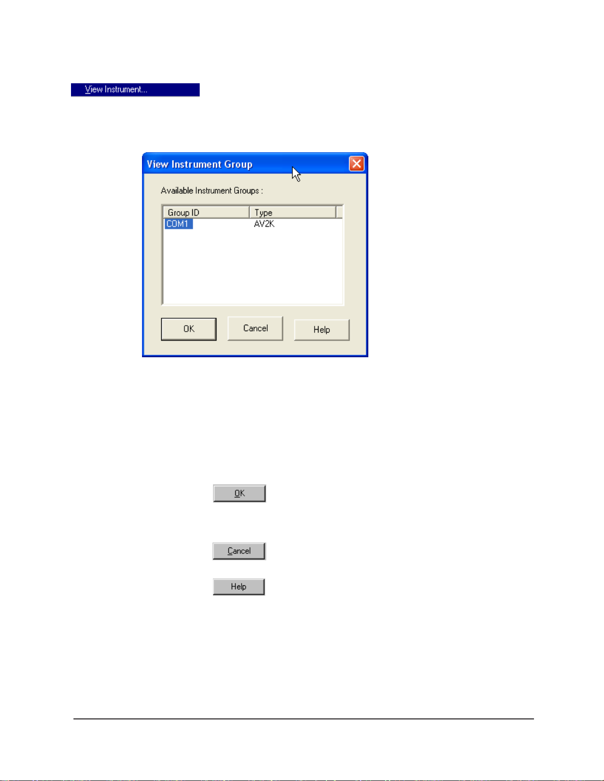
38
Main Menu
The View Instrument menu item opens the View Instrument Group
window which permits you to select the desired test instrument type from
the list of on-line instruments.
The View Instrument Group window
The View Instrument Group window is comprised of:
The Instrument Group list box
Three button options (OK, Cancel, and Help).
View Instrument Group window button options:
Opens the Sample Input window for the selected
instrument group and restores any configuration settings
for that group.
Closes the View Instrument Group window without
opening a Sample Input window.
Accesses context-sensitive help.
Available Instrument s: The Instrument Group list box in the View
Instrument window displays a list of all on-line instruments.
T o use the V iew Instrument Group window to open the desired instrument group from the list, click the GROUP ID associated with the desired
instrument(s) to select it; then click OK.
CANNON
®
miniPV-Series Automatic Viscometer with VISCPRO® Instruction & Operation Manual
Version 1.a— January, 2011; CANNON
2139 High Tech Road • State College, PA 16803 • USA
®
Instrument Company
Page 45

39
Security options
The Poll for Instruments menu item queries the hardware interface to
®
establish communications with CANNON
instruments attached to the
host computer.
Use Poll for Instruments to establish a computer connection with
instruments which may have come “on line” after the software has been
in operation. When the connection has been verified by the controlling
software via the hardware interface, the instrument name will be added
to the status bar at the bottom of the VISCPRO
®
window.
The VISCPRO® application offers a level-based security system with a
log in procedure. This system ensures that available software functions
are appropriate for the security level of the user.
Initial security settings will be completed during miniPV Series installation.
Following installation, security options may be accessed and changed from
the VISCPRO
®
Main menu by individuals who have the manager password.
Each user can be assigned a security level, which is used to determine
permitted operations. Three security levels are defined by the software:
Technician (least privileged), Manager (intermediate privilege), and
Service (maximum privilege–reserved for CANNON
®
Instrument
Company service personnel).
Initial security setup
NOTE
Users log in when using the software by typing their name and (optional)
password in the Log In window (see next section). Different security
levels offer different miniPV Series use options. Technicians are permitted to access operational features required for testing samples and
performing other routine operations. Managers may access all advanced
configuration and reporting options. The Service level permits access to
all instrument and security parameters.
The VISCPRO® software installation creates a security account for one
manager with a blank password. After VISCPRO® installation, a password should be assigned for the manager using the Change Password
menu option from Main. Managers may add or change accounts for
technician status personnel.
Use the Log In feature to identify the miniPV Series operator and/or
access security functions.
Once an operator is logged in, that operator’s name is associated with any
sample data obtained during that VISCPRO session. The operator name
may be included in analyses.
Procedure
CANNON
1. Click Log In from Main.
2. Select the desired name from the drop-down list box.
®
miniPV-Series Automatic Viscometer with VISCPRO® Instruction & Operation Manual
Version 1.a— January, 2011; CANNON
2139 High Tech Road • State College, PA 16803 • USA
®
Instrument Company
Page 46

40
3. Type the password in the Password field for the individual selected.
4. Click OK.
Use the Change Password feature to change the current user password.
Procedure
Procedure
®
1. Log in to the VISCPRO
software using the Log In command from
Main.
2. Select Change Password from the Main menu options.
3. Type in the new password in the Password field.
4. Retype the password in the Confirm Your New Password field.
5. Click OK to save the new password and close the Change Pass-
word window.
Use the Update User Information feature to update the security list of
authorized miniPV Series technicians and managers. User information
can only be updated by an individual logged in with a higher security
clearance than the user for which information is to be altered. Manager
status is necessary to change Technician information. Service status is
necessary to change Manager information. T o obtain Service status, it is
necessary to select user CANNON Instrument Company from the Log
In window and to type in the current CANNON® password. For the
current password call CANNON® at (814) 353-8000.
1. Click Log In from Main.
NOTE
CANNON
2. Select your Manager or Service level user name from the User
Name list box. Input the correct password in the appropriate field.
3. Click OK.
4. Click Update User Information from Main.
5. Select the desired user from the User Name list box.
T o delete a user, just click Remove User after selecting the user name.
The account will be immediately and permanently removed.
6. Enter and verify the desired password, and select user security status
using the appropriate list boxes.
7. Retype the password in the Confirm Password field.
8. Click Add or Update User to save your changes.
9. Click Done to exit the Change User List window.
®
miniPV-Series Automatic Viscometer with VISCPRO® Instruction & Operation Manual
Version 1.a— January, 2011; CANNON
2139 High Tech Road • State College, PA 16803 • USA
®
Instrument Company
Page 47

To use the Log Out feature, click
Log Out from Main. The current
user will be logged out of the
security list of authorized miniPV
Series technicians and managers.
The software will automatically
reset to the lowest security level. Any ongoing test operations will continue.
Adjusting Security Settings
VISCPRO® provides an interface to customize security settings for your
facility. To adjust the security settings for your VISCPRO
complete the procedure below:
1. Log in as a Manager.
2. Click Service and select the desired instrument. Then click Set
Security Levels.
Radio button options for analysis
configuration
®
software,
41
The Set Security Levels window will open.
3. To make changes to security settings displayed in the window , click
the current security level for the software option you want to change;
then click the desired setting (T echnician or Manager) from the dropdown box displaying the security levels. When you are done, click
OK to save your settings or click Cancel to exit the Set Security
Levels window without making changes.
CANNON
The Set Security Options window
®
miniPV-Series Automatic Viscometer with VISCPRO® Instruction & Operation Manual
Version 1.a— January, 2011; CANNON
2139 High Tech Road • State College, PA 16803 • USA
®
Instrument Company
Page 48

42
Print/Print setup menu items
CAUTION
Analyses Menu
Select this standard Windows® print menu item to access the Windows
®
print window. Then select print options for the currently-active analysis/
report (see Analysis options).
Select this standard Windows® print menu item to access the print setup
window . Check your printer driver documentation for additional information on print setup options.
Select the Exit option to exit ViscPRO. Or you may click on the
application title bar.
Exiting the application aborts current tests. It is the responsibility of the
user to restore the miniPV Series to a safe state using Wash Viscometer
Tube functions from the Service menu before resuming miniPV Series
testing.
Data obtained from all instruments during sample testing is stored in the
central VISCPRO® database. To view data, you must create an analysis
configuration requesting the desired sample information in the desired
format. Analysis configurations can be saved and later restored. The
analysis configuration options provide powerful tools for reporting sample
information. Refer to Chapter 6 of this manual for general information on
using the analysis options. For specific information regarding the individual analysis packages shipped with your software (e.g., CAV Data
Table, VI Matching), consult the manual chapter for that particular
analysis.
Each analysis generates a report based on instrument data in the
VISCPRO
software:
Analysis types
Error Data Export, Sample Data Export and VI Data Export
Error Log Table—lists error messages and related data.
CA V Data Table—displays test information and selected calculated
Standard VI Table—provides a report of matched samples according
Analyses menu options
CANNON
®
miniPV-Series Automatic Viscometer with VISCPRO® Instruction & Operation Manual
Version 1.a— January, 2011; CANNON
2139 High Tech Road • State College, PA 16803 • USA
®
database. The following analyses are shipped with the
analyses—configures data for output to a file, parallel port, or serial
port.
data.
to configuration information you provide.
®
Instrument Company
Page 49

The following VISCPRO® menu options are used to create and manage
analyses:
View Analysis—opens the Choose Analysis window . See View
Analysis, below , for more details.
Report Title—opens the Designate Report Title window. Permits
data entry of up to three lines of text for the report title.
Configure Analysis—Accesses Configuration options. For informa-
tion on configuring analyses, consult Chapter 6 and the manual
chapter corresponding to the particular analysis.
Save Configuration—Opens the Save Configuration window.
T ype the desired file name in the Save As: field and click OK to
save the configuration.
43
NOTE
The Configure Analysis and Save Analysis options are only available from
the Analyses menu when an analysis window is open.
Select View Analysis to select an analysis from a list of available analyses or define a new analysis.
T o display an analysis, click the View Analysis menu item from the
Analyses menu. The Choose Analysis window will appear . The
Choose Analysis window provides a list of available analyses in a list
box on the left side of the window . The analyses are organized into
similar groups using a directory tree structure.
NOTE
CANNON
The Choose Analysis window
“Unopened” report directories identified with the symbol contain one or
more analysis packages. Click on the to reveal or conceal the list.
Select the desired analysis from the directory tree. After an analysis has
been selected, you can configure the analysis to display the information
you want from the central VISCPRO® database. The Choose Analysis
window provides three options for doing this:
®
miniPV-Series Automatic Viscometer with VISCPRO® Instruction & Operation Manual
Version 1.a— January, 2011; CANNON
2139 High Tech Road • State College, PA 16803 • USA
®
Instrument Company
Page 50

44
Click the appropriate radio button . Then select the desired saved
configuration (if any) and click OK:
Select Open Selected Analysis Configuration if you wish to
create and display the selected analysis using the saved configuration highlighted in the list box on the right side of the Choose
Analysis window.
Select View and Open Existing Configuration if you wish to open
the configuration window for the analysis configuration highlighted
in the list box on the right side of the Choose Analysis window .
Select Define and Open New Configuration to open the configu-
ration window using default settings for the selected analysis.
NOTE
Window Menu
For more information on defining and using configurations, see Chapter 6.
The Window menu provides options for scaling and arranging multiple
windows/icons for screen display. In VISCPRO® you can also save and
restore a specific window configuration.
Select this standard W indows® display menu item to arrange any
minimized analysis/report or instrument windows at the bottom of the
primary application window .
Select this W indows® display menu item to resize and regroup all open
windows to view multiple on-screen reports/instruments. You may select
horizontal or vertical tiling for more convenient viewing of data.
Select this standard W indows® display menu item to resize and regroup
all open windows in an overlapping format which provides more space
for the active window.
CANNON
Select this security-protected Manager-level menu item to save the
current VISCPRO® screen configuration, including any currently-open
analyses and Sample Input windows. To restore the saved configuration
to the VISCPRO® display, click Restore Window Layout (see below).
This menu item restores the saved VISCPRO® screen configuration.
Any currently-open analysis windows will be closed before the saved
configuration is loaded. Also note that currently-open Sample Input/
Machine Status windows may be obscured by the restored configuration. To view these obscured windows, either click Window from the
VISCPRO® primary display and select the desired instrument view OR
®
miniPV-Series Automatic Viscometer with VISCPRO® Instruction & Operation Manual
Version 1.a— January, 2011; CANNON
2139 High Tech Road • State College, PA 16803 • USA
®
Instrument Company
Page 51

right-click the appropriate group button on the status bar on the bottom of the
primary window . Restoring a saved window configuration does not affect
current miniPV Series sample testing operations.
miniPV Series module menu options
45
Configure menu
In addition to the VISCPRO
software application modules for each type of CANNON
®
general instrument menu functions, unique
®
instrument
generate additional interface options. The modules determine the characteristics, function and appearance of VISCPRO
®
software menus and
windows. These instrument-specific software options (under the Config-
ure and Service menues) permit user control of important miniPV Series
operations.
The Configure menu provides the user with a powerful tool for description of miniPV Series instrument capabilities, and for customizing miniPV
Series test procedures. Once configuration settings have been determined
for optimum performance, the settings can be saved and restored using
the Save Instrument (Configure menu) and View Instrument (Main
menu) functions.
Initial factory configuration settings may be supplied on a configuration
floppy disk. Additional configurations can be created to enhance test
performance with different types of samples.
Configuration settings will need to be updated when instrument specifications or components change (sample tray types, viscometer tubes, tube
types, etc.).
Each of the configuration menu items is explained in detail in the following sections. T o access the configuration options, click Configure from
the VISCPRO
and instrument.
Print Instrument and Tray Settings
The Print Instrument and T ray Settings menu item prints instrument
and tray settings. When you select this item, a standard Print window is
opened. Select the desired print settings and click OK to print out a hard
copy of the instrument and tray settings. You may wish to retain the
printout for diagnostics, verification and record-keeping purposes.
Select Print Calibration Certificate to print calibration parameters for
your current instrument configuration. After you select the Print Cali-
bration Certificate option, the standard Windows Print dialog will be
displayed. After you have selected your print options, the VISCPRO
software will display the Save Calibration Data window . Input the
filename and location if you wish to save an electronic archive of your
printed calibration certificate to disk. Then click Save to save the data, or
®
primary display and select the desired instrument group
CANNON
®
miniPV-Series Automatic Viscometer with VISCPRO® Instruction & Operation Manual
Version 1.a— January, 2011; CANNON
2139 High Tech Road • State College, PA 16803 • USA
®
Instrument Company
Page 52

46
Cancel to exit the Save Calibration Data window without saving the
information. The calibration certificate will be printed after you exit the
Save Calibration Data window.
CANNON Instrument Company recommends saving instrument and
tray settings each time a new calibration is performed.
Select Save Instrument and Tray Settings to save certain current
instrument information, including instrument specifications and calibration
data (Instrument Settings), basic and advanced operational parameters
(Tray Settings), and previously-entered Sample ID information.
When you click the Save Instrument and Tray Settings menu item, the
Save Configuration window will open.
CANNON
The Save Configuration window
Choose a name for the Configuration by entering it in the Save As: field.
Y ou may also click on existing (saved) Configuration by clicking on the
Configuration name in the Existing Configurations list box.
When you have selected a Configuration name, click OK to save the
Configuration and exit the Save Configuration window . Or click Cancel to
exit the window without saving the Configuration. You can also delete
existing configurations by selecting them from the Existing Configurations
list box and pressing the Delete button.
Select Restore Instrument and Tray Settings to restore certain
instrument information, including instrument specifications and calibration
data (Instrument settings) basic and advanced operational parameters
(Tray Settings), and previously-entered Sample ID information.
When you click the Restore Instrument and Tray Settings menu
option, the Restore Configuration window will open.
®
miniPV-Series Automatic Viscometer with VISCPRO® Instruction & Operation Manual
Version 1.a— January, 2011; CANNON
2139 High Tech Road • State College, PA 16803 • USA
®
Instrument Company
Page 53

47
Instrument Settings
The Restore Configuration window
This is a security-protected feature. Depending on the user-set configuration options, technician-level personnel may only be able to restore
Sample ID information. Individuals logged in to VISCPRO as a Manager
will be able to restore Instrument Settings and Tray Settings. To
restore information, click on the check boxes corresponding to the desired
parameters. Then click OK.
Select Instrument Settings to open the Instrument Settings window,
which provides features for describing the miniPV Series and controlling
the instrument. These settings apply to the instrument as a whole.
Use the ID field to input instrument identification information using up to
16 alphanumeric characters.
The S/N: field displays the instrument serial number stored by the
operational firmware of the miniPV Series. This is a non-editable field.
CANNON
®
miniPV-Series Automatic Viscometer with VISCPRO® Instruction & Operation Manual
Version 1.a— January, 2011; CANNON
2139 High Tech Road • State College, PA 16803 • USA
®
Instrument Company
Page 54

48
The miniPV Series Instrument Settings window
Click on this check box to activate a software counter which will generate a warning for a tube whenever the specified number of days have
elapsed without performance of the Verify Known KV sample action.
Enter the number of days in the appropriate field.
Click on this check box to activate a software counter which will generate a warning whenever the specified number of samples have been
tested without performance of the Verify Known KV sample action.
Enter the number of samples in the appropriate field.
CANNON
®
miniPV-Series Automatic Viscometer with VISCPRO® Instruction & Operation Manual
Version 1.a— January, 2011; CANNON
2139 High Tech Road • State College, PA 16803 • USA
®
Instrument Company
Page 55

Instrument Settings window button options:
Tray Settings: Tube and Bath
Use the Tray Settings: Tube and Bath window to describe and control
test parameters for the viscometer tube. Alter the settings using the
instructions below . When you have achieved the desired configuration,
save the current instrument settings by clicking OK. T o exit the configuration screen without saving your changes, click Cancel. T o restore
software defaults, click Defaults.
saves the current instrument settings and exits the
Instrument Settings window
.
restores the default configuration settings for several
instrument options
closes the Instrument Settings window without saving
any configuration changes.
49
CANNON
The Tray Settings: Tube and Bath window
T o complete the tray configuration: Use the T ube S/N: field to input the
identifying tube serial number.
®
miniPV-Series Automatic Viscometer with VISCPRO® Instruction & Operation Manual
Version 1.a— January, 2011; CANNON
2139 High Tech Road • State College, PA 16803 • USA
®
Instrument Company
Page 56

50
NOTE For reporting and calibration purposes, each tube serial number value
should be unique for all instruments attached to a single computer.
Click on the Fast Run Tube check box if the viscometer tube is the fast
run type. The Wet T ube option is required for some viscosity determination protocols. If this option is checked, the miniPV Series automatic
determination will be preceded by an untimed sample drop, coating the
inside of the capillary with the sample material.
NOTE
Bath Temperature
CAUTION
Equilib. Tolerance
Settings for soak times may need to be reconfigured when the bath
temperature setting is changed.
Input the desired temperature for the miniPV Series Bath corresponding
to the selected tube in the Bath Temp: field and select the desired unit of
temperature measurement by clicking on the corresponding radio button.
Changing bath temperature may necessitate removing the reference
thermometer from the Bath Unit. See Inserting/removing the reference
thermometer in Chapter 2 for information on the procedure. Damaged
thermometers may contaminate the bath fluid.
Input the desired Equilib. Tolerance for the miniPV Series. The Equilib.
Tolerance is when the target temperature is reached, and remains within
the Equilibration Tolerance for least 30 seconds. The default and recommended value is 0.02.
Thermistors Radio Buttons
Soak Time Units Radio Buttons
CANNON
®
miniPV-Series Automatic Viscometer with VISCPRO® Instruction & Operation Manual
Version 1.a— January, 2011; CANNON
2139 High Tech Road • State College, PA 16803 • USA
Select 2K or 15K depending on the thermistor value used in the installed
tube.
Select the desired unit of time by clicking on the corresponding radio
button.
®
Instrument Company
Page 57

Soak time
51
Input the desired sample soak times for each bulb of the viscometer tube.
The soak time is the length of time in which the sample will remain in the
viscometer tube before being dropped. The soak time is important to
ensure temperature equilibration of the sample. The range is from 0 to
240 based on which units of time the user selected from Soak Time Units.
Constants
Tray Settings: Test
NOTE
The Tray Settings: T ube and Bath screen displays the calibration
constants (C and E) for each bulb of the viscometer tube. These values
cannot be edited from the Tray Settings . . . screen. For information on
determining bulb constants for viscometer tubes, see Calibration later in
this chapter.
When you have completed the configuration and saved the current tray
settings, you may wish to permanently store the current instrument
settings using the Save Instrument and T ray Settings item in the Configure
menu for a given instrument.
The Tray Settings: Test window is used to select parameters for
miniPV Series sample testing. Each sample drop is called a determination. Multiple determinations are possible during testing of a single
sample. Comparisons of sample drop results permit user regulation of test
precision.
The Maximum Absolute Difference option permits you to input the
maximum acceptable deviation for multi-drop samples, expressed as the
difference in the sample drop times in seconds.
The Maximum % Difference option allows you to input the maximum
acceptable deviation for multi-drop samples expressed as a percentage
(0.35 is the default percentage difference allowable). Values from 0.01 to
99.99 are acceptable. If the difference between test drop times is greater
than the acceptable deviation, the sample will be tested again until the
deviation in drop times is less than the Maximum % Difference, or until
the maximum number of determinations has been reached.
Tolerance parameters
Use greater
CANNON
®
miniPV-Series Automatic Viscometer with VISCPRO® Instruction & Operation Manual
The Maximum Determinations option permits you to select from 1-20
iterations of the test using the same sample.
Determine if the tolerance for differences between sample run times
(determinability) is going to be decided by the absolute difference in drop
time values (in seconds) or by the percentage difference between the
drop times. Click on the appropriate check box to select your choice(s).
Enter the maximum acceptable difference in measured results when
using multiple determinations (the default percent difference value is 0.35
percent and the default absolute difference value is 0.2 seconds).
Version 1.a— January, 2011; CANNON
2139 High Tech Road • State College, PA 16803 • USA
®
Instrument Company
Page 58

52
If both tolerance options are selected, the VISCPRO software will apply both criteria unless the
Use greater option is checked. If Use greater is checked, then the software will apply the less
exacting tolerance value when calculating/evaluating test results.
The Tray Settings: Test window
Use spread
Use mean
Determinations
The Use spread and Use mean radio button options determine the
manner in which the VISCPRO mathematically determines which sample
tests have met tolerance parameters. Testing is continued until a group of
samples meets the tolerance parameters and the rules for sample drop
time determination (see Determinations, below).
The Use spread option compares the individual drop time values for each
test sample with the individual drop time values of the other samples. If a
sample deviates from tolerance parameters when compared with any other
sample in a grouping, the sample is eliminated from consideration.
The Use mean option compares the individual drop time values for each
test sample with the mean (average) drop time represented by all samples
in the group. If any sample in the group deviates from the mean by a
value greater than the value specified in the tolerance parameters, the
group is eliminated from consideration.
Select the determination option by clicking on the radio button corresponding to the appropriate determination method (Always perform
maximum determinations, Use successive determinations only, or
Use any determinations).
CANNON
®
miniPV-Series Automatic Viscometer with VISCPRO® Instruction & Operation Manual
Version 1.a— January, 2011; CANNON
2139 High Tech Road • State College, PA 16803 • USA
®
Instrument Company
Page 59

Selecting sample run required and maximum determination
settings
53
NOTES
Tray Settings: Wash
Select the number of Required determinations by clicking on the
spin
controls (values from 1 to 4 are acceptable). In the same manner, select
the Maximum number of determinations which can be run for the tube
samples (values from 1 to 20 are acceptable).
VISCPRO determines the sample flow time by averaging the values of the
sample runs which correspond to the chosen criteria.
If the Always perform maximum determinations radio button is selected,
the last flow times will be used for the viscosity determination.
When you have completed the configuration and saved the current settings, you may wish to permanently store the settings using the Save
Instrument and Tray Settings.
Use the Tray Settings: Wash window to determine wash settings. For
multi-tube units, different wash settings may be selected for each tube
The Tray Settings: Wash window
Solvent rinse settings
CANNON
®
individually .
The solvent rinse settings for Solvent A and (if applicable) Solvent B are
determined using the Tray Settings: Wash window . Select a value from
0 to 18 cycles for this option (the “0” setting turns the solvent option off).
These settings determine the number of rinse cycles performed by the
miniPV-Series Automatic Viscometer with VISCPRO® Instruction & Operation Manual
Version 1.a— January, 2011; CANNON
2139 High Tech Road • State College, PA 16803 • USA
®
Instrument Company
Page 60

54
miniPV Series instrument after each test. Higher viscosity materials may
require more rinses. Lower viscosity materials may require fewer rinses,
depending on the effectiveness of the solvent.
Max Solvent fill time(s)
Solvent flush time(s)
The Max Solvent fill time(s) setting determines if/when the user receives a screen prompt instructing him to check/refill the external solvent
vessel. Select a value from 1 to 60 seconds for this option. The recommended default is 30 seconds. During this time, the VISCPRO software
monitors the filling of an internal solvent chamber in preparation for
solvent evacuation through the viscometer tube. The default setting
should allow adequate time for the required volume of solvent (approximately 12 mL) to be introduced into the internal solvent chamber under
normal conditions of vacuum/pressure. If the Max Solvent fill time(s)
setting is too low, the internal solvent chamber may not be completely
filled with solvent in the time allotted and the screen prompt may be
displayed even when the external solvent vessel contains solvent.
The Solvent flush time(s) setting determines the amount of time (in
seconds) that the solvent pump will continue to operate after the solvent
chamber has emptied all solvent into the sample vial during a wash. This
allows time for the lines and viscometer tube to be purged of solvent.
Select a value from 1 to 60 seconds for this option. The time will vary
with the pressure setting (miniPV Series right front “ear” panel).
Tube tip soak time(s)
Final dry time(s)
CANNON
The Tube tip soak time(s): setting determines the length of time that the
miniPV Series tube tip will soak in the solvent after the solvent has been
introduced into the sample vial. Select a value from 1 to 120 seconds for
this option. This is the amount of time that will be used for both a solvent
soak and a final solvent “bubble cleaning” following the evacuation of
solvent from the internal solvent chamber.
The Final dry time(s) setting determines the additional amount of time
forced air is channeled through the viscometer tube to dry it at the
conclusion of the rinse/dry cycle. Select a value from 15 to 300 seconds
for this option. The time period selected will be added to the preset dry
period of 108 seconds for normal tubes and 36 seconds for fast-run tubes.
®
miniPV-Series Automatic Viscometer with VISCPRO® Instruction & Operation Manual
Version 1.a— January, 2011; CANNON
2139 High Tech Road • State College, PA 16803 • USA
®
Instrument Company
Page 61

55
Cup Empty Time
NOTE
Tray Settings: Advanced
CAUTION
CAUTION
The Cup Empty T ime option determines the amount of time allotted for
evacuation of sample from the sample cup prior to the beginning of the
wash sequence. Select a value from 1 to 255 seconds for this option. The
evacuation time should be adjusted so the highest expected viscosity oil is
evacuated from the cup before the solvent is introduced into the solvent
chamber. Improper adjustment may result in solvent overflow if/when
solvent is evacuated into a waste line that still contains sample residue.
Be careful to consider bath temperature(s) and potential solvent hazards
when selecting solvents for use with the miniPV Series instrument.
Make certain to replace the sample vial with an empty vial prior to raising
the vial holder. Otherwise, solvent may overflow.
When you have completed the configuration and saved the current wash
settings, you may wish to permanently store the current instrument
settings using the Save Instrument and T ray Settings.
CAUTION
Select the Tray Settings: Advanced menu item to open the Tray
Settings: Advanced window used to define additional operational
parameters for sample testing with the miniPV Series instrument. It may
be necessary for you to log in as a Manager to access Advanced
settings.
Advanced settings will ordinarily be configured by a technician from
CANNON® Instrument Company when the instrument is initially installed.
Advanced settings should only be adjusted by or in consultation with a
representative from CANNON®.
CANNON
®
miniPV-Series Automatic Viscometer with VISCPRO® Instruction & Operation Manual
Version 1.a— January, 2011; CANNON
2139 High Tech Road • State College, PA 16803 • USA
®
Instrument Company
Page 62

56
The Tray Settings: Advanced window
Maximum bulb 1 fill time(s):
Min. bulb 1 selection time(s):
Maximum bulb empty time(s):
Adjust this setting to select the desired maximum fill time for bulb 1.
Acceptable values are between 20 and 400 seconds.
Adjust this setting to select the desired minimum time permitted for
selection of bulb 1 or bulb 2 for sample testing. Acceptable values are
between 0 and 20 seconds. Decreasing the setting will increase the
probability that the sample will be tested in bulb 1.
Adjust this setting to select the maximum amount of time for the oil to
drop between the target tube sensor and the bottom tube sensor during a
sample determination before the sample test is aborted. Acceptable
values are between 90 and 600 seconds.
CANNON
®
miniPV-Series Automatic Viscometer with VISCPRO® Instruction & Operation Manual
Version 1.a— January, 2011; CANNON
2139 High Tech Road • State College, PA 16803 • USA
®
Instrument Company
Page 63
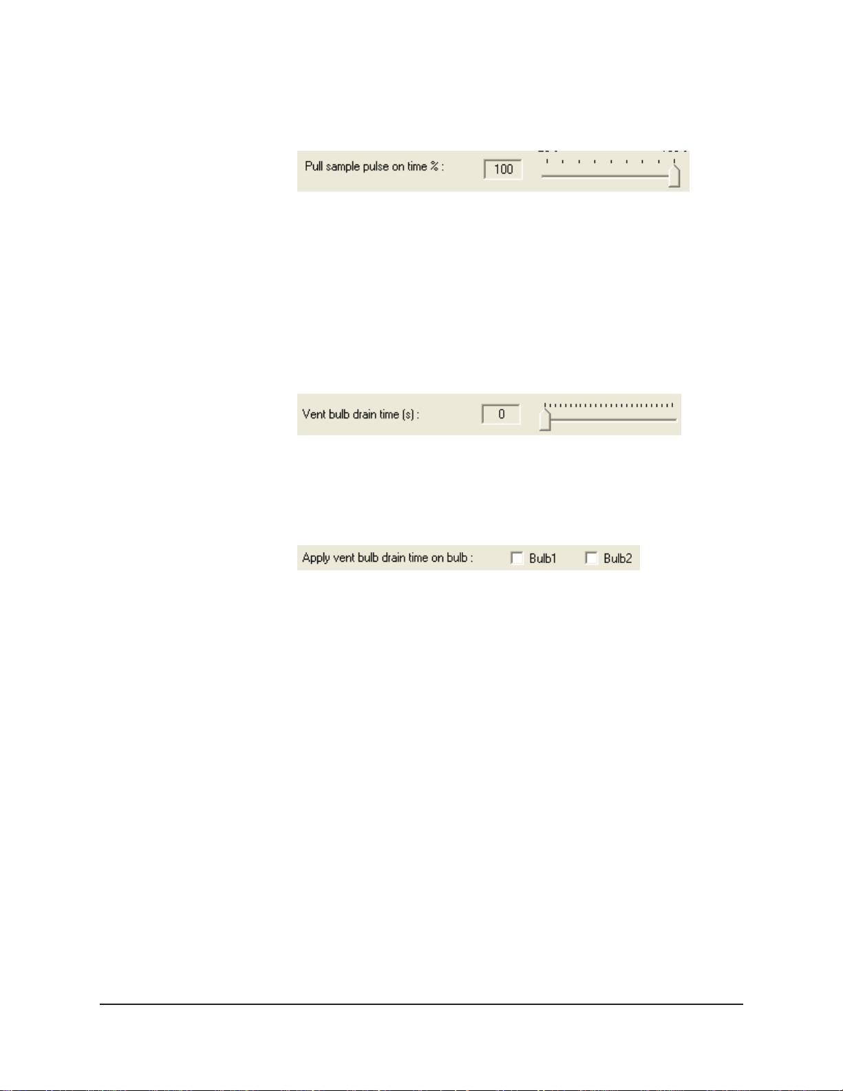
57
Maximum tube empty time %:
Pull Sample Pulse On Time
Vent Bulb Drain Time
Adjust this setting to select the percentage of the drop time between the
bottom sensor and the sensor at the top of bulb 1. The default value is
100%.
Adjust this setting to help eliminate bubbles that can occasionally be
formed as the vacuum draws some types of samples into the viscometer
tube. The pulse value is a percentage of time that the sample will be
drawn up into the tube during each five-second interval of the draw
period. A setting of 100% (default setting) will not pulse the sample. A
setting of 20 would pull the sample for one second in each five-second
interval. Sample pulsing should only be used if it is found to alleviate
bubbling during the sample draw period.
Adjust this setting such that the vent bulb and vent are cleared of sample
before the sample menious drops to the top sensor. Acceptable values are
between 0 and 250 seconds.
Apply Vent Bulb Drain Time
Bulb overdraw
Saving a configuration
CANNON
®
miniPV-Series Automatic Viscometer with VISCPRO® Instruction & Operation Manual
Version 1.a— January, 2011; CANNON
Select which bulb to apply the Vent bulb drain time parameter.
Use the Bulb Overdraw button/window to set the the amount of time in
seconds that the instrument will draw sample AFTER the sample meniscus has covered the target sensor in the viscometer tube. More viscous
materials may require a larger overdraw time to ensure that the sample
meniscus does not dip below the target sensor during temperature
equilibration.
Proper adjustment of the overdraw can maximize efficiency of the test
cycle. Too much overdraw can contaminate vacuum lines and interfere
with pump operation. T oo little overdraw can interfere with the initiation
of sample testing following the temperature equilibration period. Note
that lighter oils will be pulled higher in the bulb.
Whenever you have altered instrument, tray or sample configuration, you
should save the resulting settings as a new or existing configuration. To
save current settings, use the Save Instrument option:
®
Instrument Company
2139 High Tech Road • State College, PA 16803 • USA
Page 64

58
Procedure
Calibration
1. From the VISCPRO
®
primary menu options, click Configure.
2. Select the desired instrument and click Save Instrument & Tray
Settings. The Save Configuration window will appear.
3. Type a name for the new configuration in the Save As: box. Or click
an existing configuration from the configuration list box.
4. Click OK to save the configuration. Or click Cancel to exit the Save
Instrument & Tray Settings window without saving your changes.
The Calibration window provides controls for calibrating each bulb
associated with your instrument. You may need to log onto the system as
a Manager to access these security-protected calibration functions.
Use the bulb spin controls
to display current constants and valid
check standard data available for calibration of each bulb.
Calibration constants are determined individually for each bulb. Data for
automatic calculation of tube calibration constants is derived from check
standards run using that tube.
For information regarding the miniPV Series calibration procedure, see
Chapter 3, Calibrating the miniPV Series.
NOTE
The Calibration window options are described briefly below:
Date selection: The calibration program uses data from previously-run
standards to determine the calibration constants. To select the desired
standard data, use the No older than [x] days spin controls
to set the
date parameters for the database search (if “1” is selected, only the
standards run in the past 24 hours will be used).
Bulb selection: Viscometer bulbs are numbered from the bottom to the
top of the viscometer tube. Use the spin controls to select the correct
bulb for calibration.
Data selection: Test data from standards run with the miniPV Series
within the specified Date parameter will be automatically displayed in the
list box.
To select and deselect the data from the sample runs to be used for the
calibration, press and hold the C key and click on the samples to
highlight those you wish to include in calibration calculations.
Sample run data from at least two different standards for each bulb at
each calibration temperature must be available for calibration calculations
to be performed.
CANNON
After you have selected the desired data, release the C key and click
Calculate new constants to update values for C and E.
®
miniPV-Series Automatic Viscometer with VISCPRO® Instruction & Operation Manual
Version 1.a— January, 2011; CANNON
2139 High Tech Road • State College, PA 16803 • USA
®
Instrument Company
Page 65

You may evaluate the accuracy of the new calibration constants by
comparing the known viscosity for the standard with the calculated
viscosity for each standard selected for the new calibration. This difference is displayed as a percentage in the last column (% Diff) of the
updated sample list box.
59
Show Calibration Data
The Show Calibration Data button is a toggle that will permit you to
compare current and new calibration data and constant information.
Press the Show Calibration Data button once to view the current
calibration information. Note that the button name will change to Display
Sample Data. Press the button again to display the new calibration data.
When/if you are satisfied with calculation results, click on Update Tube
to save calibration values for the current configuration. The new data will
become the current data.
If the difference is still too great, repeat the calibration process until the
difference falls within acceptable limits (refer to the precision statement
in ASTM D445).
The Calibration window
NOTE
CANNON
®
miniPV-Series Automatic Viscometer with VISCPRO® Instruction & Operation Manual
Version 1.a— January, 2011; CANNON
2139 High Tech Road • State College, PA 16803 • USA
You must click Update tube before changing bulbs if you wish to save the
new calibration constants for that bulb. If you close the Calibration window
without updating the tube, the new calibration information will not be
saved.
®
Instrument Company
Page 66

60
Service menu
Bypass .... option
CAUTION
To access the service menu items, click Service from the VISCPRO
®
primary display and select the desired instrument.
The Monitor window permits the user to view current operational values
for the miniPV Series instrument. These settings may be helpful to
CANNON
®
technical personnel when troubleshooting difficulties with
the miniPV Series.
Select Wash viscometer tube to open the Wash viscometer tube
window .
Click Begin W ash to initiate the wash cycle. The Status: indicator will
display and update current actions.
T o begin washing an evacuated sample cup, click the option box to make
certain that the Bypass initial cup evacuation option is selected.
Do not use this option with a filled cup or the cup will overflow.
When the Wash cycle has been completed, click Done to exit the Wash
viscometer tube window.
NOTES
CAUTION
The Wash operation cannot be executed if the tube is currently running a
sample. To terminate the Wash cycle at any time, click Abort Wash.
The Wash viscometer tube function overrides automatic miniPV Series
software operations. Verify that the tubes are clean and dry before initiating computer-controlled sample testing.
CANNON
®
miniPV-Series Automatic Viscometer with VISCPRO® Instruction & Operation Manual
Version 1.a— January, 2011; CANNON
2139 High Tech Road • State College, PA 16803 • USA
®
Instrument Company
Page 67

T o adjust the vacuum/pressure settings for the miniPV Series, click
Service from the VISCPRO menu options and select the desired instrument group and instrument. Then click Adjust V acuum/Pressure to
open the Adjust Vacuum/Pressure window .
Select the desired adjustment (vacuum or pressure) and then follow the
screen prompts to complete the adjustment procedure, using the appropriate controls on the instrument wing panel. The prompts will display
recommended vacuum/pressure settings and will also indicate how
adjustments may be made to alter the settings.
61
To calibrate for temperature, see Chapter 3 for details. Temperature
calibration requires a reference thermometer with an accuracy meeting
the precision specification of ASTM D445.
To zero temperature offsets, click the Service/Clear Temperature
Offsets menu option for the desired instrument. The Zero Temperature
Offsets window will open. Click the check box to select each desired
action. Then click OK to clear the selected settings.
If the Clear Current Offset option is checked, VISCPRO will clear the
calibration point for the current bath temperature.
CANNON
®
miniPV-Series Automatic Viscometer with VISCPRO® Instruction & Operation Manual
Version 1.a— January, 2011; CANNON
2139 High Tech Road • State College, PA 16803 • USA
®
Instrument Company
Page 68

62
the Clear General Offset option is checked, VISCPRO will clear the
(factory-preset) General Offset for all temperatures for the instrument.
This Instrument Setting cannot be restored except from a previouslysaved Configuration. It is not recommended that you exercise this option
without consulting with CANNON Instrument Company personnel.
Prewash option
Trip Point Only option
NOTE
CANNON
To train tube sensors (required for miniPV Series operation at each
desired temperature setting) click the Service/Train T ube Sensors
menu option for the desired instrument. The Train T ube Sensors
window will open. Click the check box to select each desired option.
Then click the Start button to initiate tube sensor training.
Select this option if the tube needs to be cleaned and dried prior to
training. The Prewash option will execute a tube cleaning cycle prior to
beginning the sensor training.
Select this option only if the tube sensor has been previously trained and
requires only a validation/adjustment of the trip point settings (the electrical current level and fluctuations associated with the passing of the
sample meniscus). The Only option will reduce the time required to
accomplish these functions signficantly , but will not check/adjust basic
power levels for instrument operation.
The miniPV Series will not test samples until sensor training has been
performed at the test temperature.
At the conclusion of the sensor training, the “Learned” indicators for the
top, middle and bottom sensors should display in green. If sensor training
has not been successfully accomplished, the “Opened” and “Shorted”
sensor indicators may provide helpful diagnostic information. Consult with
CANNON Instrument Company personnel if problems with sensor
training persist.
®
miniPV-Series Automatic Viscometer with VISCPRO® Instruction & Operation Manual
Version 1.a— January, 2011; CANNON
2139 High Tech Road • State College, PA 16803 • USA
®
Instrument Company
Page 69

63
To set security levels, first log into the VISCPRO software as a Manager. This will permit you to determine Manager or Technician accessibility for the following protected menu-accessible functions:
Configuration:
Instrument Settings
Tray Settings: Tube & Bath
Tray Settings: Test
Tray Settings: Wash
Tray Settings: Advanced
Calibration
Service:
Adjust V acuum
T emperature Calibration (saved as Instrument Settings)
Zero Temperature Offsets (saved as Instrument Settings)
Train T ube Sensors
To make security changes, click Service/Set Security Levels for the
desired instrument. The Service/Set Security Levels window will open.
Current security settings will be displayed. To change the security level
for a protected function, click on the Security Level cell opposite the
function name until the Manager/T echnician drop-down box is displayed.
Then click the desired security level to select it.
CANNON
®
miniPV-Series Automatic Viscometer with VISCPRO® Instruction & Operation Manual
Version 1.a— January, 2011; CANNON
2139 High Tech Road • State College, PA 16803 • USA
®
Instrument Company
Page 70

64
When you have finished updating settings, click the Save button to save
settings and close the Set Security Levels window. Or click Cancel to
close the window without saving changes.
Testing samples—software options
This section of the manual provides information on using the software to
perform common miniPV Series operations. For a step-by-step procedure
detailing both hardware and software operations involved in sample
testing, refer to Chapter 2.
Entering sample ID information
Procedure
NOTE
®
1. From the VISCPRO
primary menu, click on Main.
2. Select View Instrument from the menu .
3. Select the desired instrument group from the list box in the View
Instrument window.
If you do not see the desired instrument listed in the list box, make certain
that the instrument is turned on and is on-line (verify cable connections to
the computer). Then click the Refresh button to scan for additional on-line
instruments.
4. When you are done, click OK. The Sample Input window for the
selected instrument will appear.
5. To input sample identification information for the samples to be run,
first select the correct tray for the test by clicking on the tab corre-
sponding to the tray.
6. After the tray has been selected, click on the sample number in
parentheses (or press 2) to access the sample ID field.
7. Enter the desired sample ID, using up to 21 alphanumeric characters;
then press the T or R key.
Selecting sample actions
8. Whenever a new sample ID is entered, the sample action defaults to
NOTE
CANNON
®
miniPV-Series Automatic Viscometer with VISCPRO® Instruction & Operation Manual
To select more than one sample at a time from the sample list box,
highlight the first sample and the press the S key and click on the
last sample, or just press and hold the C key and click on individual
samples to be selected. When you have completed sample selection,
right-click the mouse on any of the selected samples to select the desired
sample action for all highlighted samples.
9. Select the desired sample action from the window by clicking on it.
Version 1.a— January, 2011; CANNON
2139 High Tech Road • State College, PA 16803 • USA
Measure Sample Viscosity. To access all sample action options,
highlight the desired sample and right-click the mouse or press 5.
The Sample Action popup window will appear.
®
Instrument Company
Page 71

65
Sample actions
The Sample Action popup
Viscosity Action window
No action—clears action column for highlighted samples. No testing
will take place for this tray position.
Measure kinematic viscosity—measures sample viscosity .
Verify Known KV—measures sample viscosity at the conclusion of
the automated test and tags data for possible use in calibrations/
reports.
Configure—Opens the Viscosity Action window (see next section)
to select test actions for selected individual samples/standards. The
Configure options will vary depending on the selected sample action
(Measure Sample Viscosity or Verify Known KV).
Delete—Deletes currently-selected sample data. Samples in suc-
ceeding tray positions will be moved up to fill the empty “slot”.
Insert At—Inserts a sample field at the currently-selected location.
Copy All Selected Samples—copies selected sample IDs
Paste Into Selected Samples—pastes selected sample IDs
Sequential Sample IDs—Numbers selected samples automatically .
Clear All Trays—Clears sample data for all trays.
The Viscosity Action window permits you to set test parameters for
individual samples, overriding the general settings. For information on
general settings, refer to Tray Settings: Test.
CANNON
The Viscosity Action window
®
miniPV-Series Automatic Viscometer with VISCPRO® Instruction & Operation Manual
Version 1.a— January, 2011; CANNON
2139 High Tech Road • State College, PA 16803 • USA
®
Instrument Company
Page 72

66
Sequential Sample IDs—creates a numeric sequence for the
highlighted sample ID(s) in the list box. You have the option of
selecting a standard alphanumeric prefix and/or suffix to accompany
the sequence numbers, and you also can select the starting numeral in
the sequence.
Procedure
1. To use the Sequential Sample IDs feature, highlight the desired
sample tray location(s) in the list box (or skip to the next step to
select all).
2. Right-click any of the desired ID locations and select Sequential
Sample IDs from the Sample Action popup.
3. Enter necessary information in the Assign Sequential Sample IDs
window:
Assign Sequential Sample IDs window
Prefix—Input a character string to be used as an identifier
Suffix—Input a character string to be used as an identifier
Starting ID—Input a number to start the numeric sequence
Number of Samples—Select the number of samples in the high-
lighted block which are to be sequentially numbered
Use as Format—If checked, this feature activates a “wrap-around”
function for sequential numbering like an odometer (if 001 was
input, the sequence would restart at 001 every 100 samples).
4. When done, click OK.
NOTE
The VISCPRO® software “remembers” the last number in the last sequence and will place the next number in the sequence in the St arting ID
field the next time the Sequential Sample IDs option is selected.
Viscosity Action for viscosity standards
The Viscosity Action window for KV verification is identical to the
Viscosity Action window for measurement of kinematic viscosity (see
image, previous section), except that there is an additional field provided
(Check St andard V iscosity) for input of the known viscosity of the
standard.
CANNON
®
miniPV-Series Automatic Viscometer with VISCPRO® Instruction & Operation Manual
Version 1.a— January, 2011; CANNON
2139 High Tech Road • State College, PA 16803 • USA
®
Instrument Company
Page 73

The viscosity of the standard must be entered in the Check Standard
Viscosity field in order that the resultant viscosity determination may be
used for verification and calibration.
Copy & Paste Sample ID data entry options
The VISCPRO® Sample ID data entry screen supports Copy and Paste
options.
67
Copying Sample IDs
Pasting Sample IDs
Copying/pasting multiple IDs
Inserting/deleting a sample ID in the test sequence
T o copy a Sample ID entry , including the configuration information,
highlight the desired line(s) from the Sample List Box and right-click your
mouse to access the Sample Action window. Then select Copy All
Selected Samples from the menu options. OR you can use the C-C
key combination.
T o paste previously copied Sample ID entry information into another tray/
sample location within the same instrument group, highlight the desired
line(s) in the Sample List Box and right-click your mouse to access the
Sample Action window. Then select Paste Into Selected Samples
from the menu options. OR you can use the C-V key combination.
You may copy or paste a block of (multiple) sample ID entries using the
same procedure described above. When pasting multiple entries, make
certain to select the same number of sample locations as were initially
copied. If you select a larger number , only the original copied number of
entries will be pasted. If you select a smaller number, information for the
last sample(s) in the block will not be copied.
T o insert a sample ID into an existing sample run test sequence, highlight
the desired sample location in the sample run sequence and press I.
OR highlight the desired ID number , click the right mouse button, and
select Insert At from the Sample Action options.
CAUTION
CANNON
The existing sample entries will be moved down one position in the
sequence and you can enter the new sample ID information at the cursor.
If the list box already contains a sample ID for every position on the tray ,
the sample data for the final position will be discarded when a position is
cleared for new data.
T o delete one or more sample IDs and move all remaining samples in the
sequence up in position, highlight the sample ID(s) you wish to delete and
press the D key. OR you may right-click in the highlighted block and
select Delete from the sample action options window . The highlighted
sample (or samples) will be deleted and any existing sample entries
following the removed items will be moved up to take their place in the
sample run sequence.
®
miniPV-Series Automatic Viscometer with VISCPRO® Instruction & Operation Manual
Version 1.a— January, 2011; CANNON
2139 High Tech Road • State College, PA 16803 • USA
®
Instrument Company
Page 74

68
Saving Sample ID information
Many users will test the same series of samples on a regular basis for
trend analysis and other quality control objectives. T o save time with
Sample ID data entry, VISCPRO provides an option for saving and
recalling Sample ID information.
Saving Sample IDs
To save Sample IDs, complete your sample ID data entry (see previous
sections) from the Sample Input window , then click the Save IDs
button. The Samples window will open.
Restoring Sample IDs
Input an ID for the saved sample sequence in the Save As: field. Then
select which instrument(s) to associate with the Sample ID sequence.
Then click OK.
T o restore Sample IDs previously saved, click Configuration and select
the desired instrument. Then click Restore Instrument and T ray
Settings from the Configuration options. The Load Instrument and
Tray Settings window will open.
Select which data is to be restored by clicking on the desired Restore
options (Restore Instrument Settings, Restore T ray Settings, and/or
Restore Sample Information). The Load Instrument and Tray
Settings window permits you to restore the following Instrument
Settings: Instrument UserID, check standard prompts, temperature
calibration offsets
The Load Instrument and T ray Settings option permits you to restore
the following Tray Settings: T ube S/N, tube type, wet tube option, bath
temp, and tube calibration constants.
CANNON
®
miniPV-Series Automatic Viscometer with VISCPRO® Instruction & Operation Manual
Version 1.a— January, 2011; CANNON
2139 High Tech Road • State College, PA 16803 • USA
®
Instrument Company
Page 75

Click the name of the desired confiugration to highlight it. Then click OK.
Selected settings will be restored.
69
The Load Instrument and Tray Settings window
miniPV Series analysis modules
The VISCPRO® software is shipped with several analysis modules which
can be used to create reports based on sample test data. For general
instructions on using analyses, see Chapter 6, Analysis Configuration
Options. For information on a specific analysis module included with your
miniPV Series package, see the chapter on the particular analysis.
Configuring the VI Matcher
VI Matching with VISCPRO
®
The VI Matcher is a VISCPRO® software feature that functions in
tandem with the VI analyses to enable Viscosity Index (VI) calculation
from sample data residing in the VISCPRO® database.
Viscosity Index calculations require kinematic viscosity data derived from
samples tested at a high and a low temperature. The VI Matcher permits
the user to define which viscometer tubes are high temperature tubes and
which are low temperature tubes.
After the VI Matcher has been initially configured by the user (this is
ordinarily done during initial instrument setup), the VI Analysis can be
used to automatically scan the VISCPRO
with matching Sample IDs. If samples with an identical Sample ID have
been tested on a low temperature tube and a high temperature tube within
an 8-hour time span, the VI for those samples can be calculated and
®
sample database for samples
CANNON
®
miniPV-Series Automatic Viscometer with VISCPRO® Instruction & Operation Manual
Version 1.a— January, 2011; CANNON
2139 High Tech Road • State College, PA 16803 • USA
®
Instrument Company
Page 76

70
Configuration procedure
NOTE
displayed on the VI analysis. The VI Matching function is always indicated on the VISCPRO
®
status bar, whether or not a VI domain (viscom-
eter tube set) has been defined.
To configure the VI Matcher:
1. Load the VISCPRO
®
software.
2. Log on to the system as a Manager (a password may be required) to
access the VI Matcher function, which is security-protected.
For more information on the security log-in procedure, see Security
Options, this chapter.
3. Select VI Matching—General Configuration from the Configura-
tion menu options. The General Configuration window will appear .
NOTE
CANNON
The VI Matcher General Configuration window
4. Click on the Allow Matching of Invalid Samples box if you wish to
permit VI matching of samples with flow times exceeding the
specified tolerance for repeatability .
The VI Matcher does not match invalid samples UNLESS the Allow
Matching ... box is checked. The VI Matcher never matches unsuccessful
samples (samples with no flow time and a displayed kinematic viscosity of
“0”). If one of the samples ran successfully at one temperature but not at
the other, the good sample can still be used for VI matching if the failed
sample is rerun within the time frame selected for the VI Matching Date
Filter for the analysis.
5. Click on the ADD button to add a new VI configuration.
®
miniPV-Series Automatic Viscometer with VISCPRO® Instruction & Operation Manual
Version 1.a— January, 2011; CANNON
2139 High Tech Road • State College, PA 16803 • USA
®
Instrument Company
Page 77

6. Click on the serial numbers in the Select Low T emperature Tubes
list box which correspond to tubes that should be configured as low
temperature tubes by the VI Matcher. As you do so, the serial
numbers will be added to the Selected Tubes list box.
71
NOTE
Samples must have been previously run in a tube in order for the tubes to
show up in the Select T ubes list boxes
To “de-select” a selected tube, click again on the highlighted tube serial
number
7. Click on the tubes in the Select High T emperature Tubes list box
which correspond to tubes that should be configured as high tempera-
ture tubes by the VI Matcher. As you do so, the serial numbers will
be added to the Selected Tubes list box.
8. When you have finished adding low and high temperature tubes, click
OK to save the configuration and exit the General Configuration
window .
NOTES
T o exit the General Configuration window without saving the configuration,
click Cancel.
For information on creating VI analyses, see the manual chapter corresponding to the desired analysis.
Turning off the VI Matcher
The VI Matcher essentially function as a separate instrument and is
indicated as such on the VISCPRO® Status Bar. If you wish to terminate
VI matching, you will need to delete any VI domain(s) using the Delete
button from the General Configuration window . When no domains are
defined, the VI Matcher does not function.
Handling errors
VISCPRO® errors
CANNON
®
miniPV-Series Automatic Viscometer with VISCPRO® Instruction & Operation Manual
The miniPV Series instrument software returns three types of errors
during operation: bath errors, fatal errors and tray errors. Bath and tray
errors are sample/tray specific, and may affect test results for a given
sample. Such results will be indicated as invalid. Fatal errors may be
hardware-related, and can produce a FAULT condition (see Chapter 5,
Handling fault conditions).
Version 1.a— January, 2011; CANNON
2139 High Tech Road • State College, PA 16803 • USA
®
Instrument Company
Page 78

72
This page intentionally left blank.
CANNON
®
miniPV®-HX Automatic Viscometer with VISCPRO® Instruction & Operation Manual
Version 1.0— January , 2011; CANNON
®
Instrument Company
2139 High Tech Road • State College, PA 16803 • USA
Page 79

CHAPTER
73
5
OPERATING, MAINTAINING
AND SERVICING THE miniPV Series
This chapter of the miniPV Series Instruction & Operation Manual
contains information regarding the operation, service and maintenance of
the miniPV Series instrument. For additional information on required
utilities, instrument installation and setup, refer to Chapter 1.
miniPV Series components
The standard miniPV Series installation includes these primary components:
Bath unit Waste Receiver assembly Power supply
NOTE
Bath Unit
CANNON
The installation also requires user-supplied solvent vessels. CANNON
supplies two G-38 reagent bottle caps (for recommended solvent vessels).
The user must ensure solvent compatibility for dual solvent systems,
since solvent residue will mix in the system. Additionally , any new solvent s
should be compatible with previously-used solvents, since residue from
original solvents may remain in the solvent lines and/or Waste Receiver.
The Bath Unit houses the primary control and operating systems for the
miniPV Series, including modular service components, temperature bath
with viscometer tube, carousel vial holder, and related hardware.
®
miniAV®-HX Automatic Viscometer with VISCPRO® Instruction & Operation Manual
Version 1.0— January, 2011; CANNON
2139 High Tech Road • State College, PA 16803 • USA
®
Instrument Company
Page 80

74
Bath Unit connections
For information regarding Bath Unit connections, refer to the installation
section of Chapter 1.
Solvent Dispensing System
The miniPV Series is equipped with a solvent system used to wash the
viscometer tubes after each sample test. The system consists of the
internal and external solvent and drain lines, the user-supplied solvent
vessel, and the W aste Receiver assembly (including solvent dispensing
unit). Appropriate solvent containers may be acquired from many suppliers, including JustRite
http://www.justritemfg.com/containes.tpl
http://www.nalgenelabware.com/products/productsIndex.asp
Maintaining the solvent system
The miniPV Series requires solvent, which is used to wash the viscometer tube and rinse the sample vial after each sample analysis. The
solvent system consists of the solvent containers, the solvent distribution
and drain lines, and the Waste Receiver.
The user-supplied solvent container(s) provide the solvent necessary to
clean the viscometer tubes before and after samples are tested. The
solvent delivery lines distribute solvent to the viscometer tube(s). The
drain lines collect the waste sample/solvent from the viscometer tubes,
and transfer waste materials from the washing station to the Waste
Receiver.
®
and Nalgene® (see weblinks below).
Solvents
CAUTION
WARNING
The miniPV Series is compatible with aqueous and hydrocarbon-based
(heptane, hexane, toluene and acetone) solvents. Please contact CANNON Instrument Company with any questions regarding solvent compatibility with instrument components. The supplied Waste Receiver is
polypropylene. This material should be suitable for solvents/samples
compatible with the miniPV Series.
When configured for dual solvent operation, the miniPV Series is capable
of using both a washing and a drying solvent for certain applications. The
solvents are selected by the user. Ensure compatibility of dual solvents at
all times. If switching from one solvent to another with potential compatibility problems, make certain to empty the Waste Receiver and flush the
solvent lines several times with a neutral solvent. CANNON® Instrument
Company is not responsible for damage to the solvent system caused by
a combination of user-selected solvents.
Selection, handling and disposal of solvents are the responsibility of the
user. CANNON® Instrument Company does not make specific solvent
recommendations. Refer to the Material Safety Data Sheet (MSDS)
provided with the solvent material, and exercise the necessary safety
precautions. Use extreme care when working with hazardous solvents.
CANNON
®
miniPV-Series Automatic Viscometer with VISCPRO® Instruction & Operation Manual
Version 1.a— January, 2011; CANNON
2139 High Tech Road • State College, PA 16803 • USA
®
Instrument Company
Page 81

75
Application compatibility
Checking solvent levels
Filling the solvent container(s)
Solvent fill procedure
NOTE
WARNING
The solvent used in a particular viscometer tube must be able to dry at
the test temperature of the tube (during the washing cycle). Choose the
appropriate solvent accordingly .
It is the responsibility of the operator to visually monitor the amount of
solvent remaining in the solvent container. Check the solvent container
liquid level frequently . When the solvent level drops to within 2.5-5.0 cm
(1-2") of the bottom of the solvent container, it should be refilled.
Check the volume of the solvent container(s) at the beginning of every
work shift to avoid inadequate washing during testing.
1. Remove the lid from the user-supplied solvent container.
Whenever performing solvent fill procedures, verify secure installation of
the 20-micron filter on the end of the solvent line to the miniPV Series
instrument.
Use appropriate precautions when handling the solvent lines. Avoid spilling
or splashing solvent. Always use appropriate MSDS procedures when
handling samples/solvents.
Emptying the Waste Receiver
Procedure
WARNING
WARNING
2. Refill the solvent container from the solvent source. Do not overfill!
3. Replace the weighted filter end of the miniPV Series solvent line in
the solvent container. Make certain the filter end is at the bottom of
the solvent container.
Waste sample/solvents can present possible environmental and health
hazards. Dispose of all waste materials in accordance with environmental and
safet y regul ations.
Check the volume of the Waste Receiver frequently to avoid spillage/
overflow.
1. Disconnect the Waste Receiver from the cap containing the drain
lines.
Use appropriate precautions when handling the drain tubes. Avoid spilling
or splashing waste material collected in the tubes. Always follow appropriate MSDS procedures when handling samples/solvents.
CANNON
2. Pour the collected solvent/sample mixture out of the Waste Receiver
into a proper waste storage container.
3. Securely reconnect the cap with drain tubes to the Waste Receiver.
®
miniPV-Series Automatic Viscometer with VISCPRO® Instruction & Operation Manual
Version 1.a— January, 2011; CANNON
2139 High Tech Road • State College, PA 16803 • USA
®
Instrument Company
Page 82

76
WARNING
Dual-solvent washing
Dual-solvent action
Viscometer tubes
Waste sample/solvents can present possible environmental and health
hazards. Dispose of all waste materials in accordance with environmental and
safet y regulations.
For testing heavy or hard-to-clean materials, CANNON® Instrument
Company recommends a dual-solvent washing system. The dual-solvent
washing process uses two different solvents. The first wash might
ordinarily use a heavy solvent to clean the sample residue out of the
viscometer tubes. The second wash might use a lighter solvent to remove
any remaining sample/solvent residue and dry the viscometer tube. Test
temperature(s) must be carefully considered when choosing solvents.
To engage the dual-solvent washing, make certain that desired wash
®
options are selected in the VISCPRO
software for Solvent A (washing
solvent) and Solvent B (drying solvent). Follow the instructions in the
Installation section of this manual to correctly configure the instrument for
dual solvent operation.
The miniPV Series is equipped with a borosilicate glass capillary viscometer tube having a wide viscosity range. The upper viscosity limit is up to
100 times the lower viscosity limit, depending on the tube type. Each 100fold viscometer tube contains three thermistors used for sensing the level
of the sample within the tube.
Thermistor operation
The tube thermistor detects the change in thermistor temperature associated with the passing of the sample meniscus, and records the time
accurately to within one-hundredth (0.01) of a second.
Timing bulb determination
As the sample is drawn into the viscometer tube, the VISCPRO® software automatically determines which timing bulb will be used to test the
sample.
The sample will be drawn into the bulb above the upper timing thermistor.
That bulb will serve as the overflow bulb for that particular test run.
NOTE
The numbers listed in this table are approximations, not absolute values.
sretemaraPnoitceleSbluBVAinim
2bluBgnimiT 1bluBgnimiT
timiltScrewolx01-1timiltScrewolx01>
CANNON
®
miniPV-Series Automatic Viscometer with VISCPRO® Instruction & Operation Manual
Version 1.a— January, 2011; CANNON
2139 High Tech Road • State College, PA 16803 • USA
®
Instrument Company
Page 83

Carousel Adjustments
Homing the Carousel
1. From the Service menu in ViscPRO, select miniPV Series Motor
Control.
2. Check Home Motors.
3. Click Start.
4. The carousel will home itself.
NOTE Factory Preset refer to the instructions below only if out of Adjustment.
Adjusting sample tray height
1. Ensure the R208 driver units have been properly adjusted and the
power is off.
2. Open the motor driver housing and connect a multi-meter to GND and
EHOME.
3. Rotate the 7/64 socket cap head screw (located within the exhaust
port) clockwise until it stops.
77
4. Set the multi-meter to the continuity setting.
5. Rotate the socket head cap screw counter clockwise until continuity is
achieved.
6. Once continuity has been achieved rotate the screw an additional turn.
7. Rotating the socket head cap screw in a clockwise manner lowers the
sample tray. Rotating the socket head cap screw in a counter-
clockwise manner raises the sample tray.
Adjusting Sample Tray Force
1. Ensure the stepper motors are disconnected from the R208 units and
power to the instrument is off.
2. Connect the positive probe of the voltmeter through the slot of the
elevate R208 cover and attach it to the lead of the potentiometer.
The elevate driver is located closest to the instrument.
miniAV-X with front cover screw highlighted
CANNON
®
miniPV-Series Automatic Viscometer with VISCPRO® Instruction & Operation Manual
Version 1.a— January, 2011; CANNON
2139 High Tech Road • State College, PA 16803 • USA
of C2).
3. Connect the negative probe of the voltmeter to logic ground (“-” lead
®
Instrument Company
Page 84

78
4. Apply power to the instrument and adjust the potentiometer to get a
reading of 0.50V for the elevate driver.
5. Turn off the power to the instrument.
6. Disconnect the positive probe from the potentiometer lead of the
elevate driver.7. Connect the positive probe to the potentiometer
lead of the rotate driver. The rotate driver is located furthest from
the instrument.
7. Apply power to the instrument and adjust the potentiometer to get a
reading of 0.34V for the rotate driver.
8. Turn off the power to the instrument and remove the voltmeter
probes.
9. Connect the stepper motors to the corresponding drivers.
NOTE
Temperature bath
Bath fluid
Filling the bath
The units are shipped with current cutback enabled i.e. the micro
switch is towards the white dot. This is the correct mode of operation
and should not be changed.
We are using quarter step resolution which means pin 3 and pin 7
are connected and pin 2 and pin 7 are not connected.
The temperature bath is capable of maintaining constant temperatures
between 20°C and 100°C. Silicone bath fluid is circulated via a central
stirring shaft with twin impellers. The bath also contains stainless steel
resistance heating elements. Solid state temperature control circuits
provide proportional control with reset. An over -temperature probe is
installed to protect all heating elements. It protects the bath from over
heating.
The temperature bath is ordinarily filled with Dow Corning 200 10 cSt
silicone fluid, available from CANNON® Instrument Company.
Fill procedure
CANNON
CAUTION
Remove MAINS power from the instrument before beginning the fill
procedure. The fill procedure should be performed when the bath fluid is at
ambient lab temperature.
1. Obtain the (supplied) bottle, Fill Cap Assembly and bath fluid.
2. Remove the top panel of the bath unit to view and access internal
components.
3. Fill the bottle with silicone fluid and screw the Fill Cap Assembly onto
the bottle. Ensure that the breather tube is positioned with the tube
opening at the bottom of the bottle.
®
miniPV-Series Automatic Viscometer with VISCPRO® Instruction & Operation Manual
Version 1.a— January, 2011; CANNON
2139 High Tech Road • State College, PA 16803 • USA
®
Instrument Company
Page 85

4. Insert the end of the fill tube from the Fill Cap Assembly into the slot
in the top of the bath flange.
5. Lift and invert the bottle to begin introducing 900 mL of the appropri-
ate grade of ambient-temperature silicone bath fluid into the bath.
Add a small amount first and check for leaks. Then continue filling to
the cold fill level, marked by a decal cold fill line. The cold fill line is
approximately 3 centimeters (1.25”) below the bottom of the top bath
flange.
CAUTION
Do NOT overfill the miniPV Series bath, as the liquid level will rise with
temperature.
6. When done, lower and invert the bottle to stop the fluid flow, remove
the fill tube from the bath, and detach the Fill Cap Assembly. Store
the bottle and Fill Cap Assembly in a safe place for future use.
7. Replace the bath top cover. Check the bath for leaks to complete the
fill procedure. Tighten fittings if necessary.
79
NOTE
Draining the bath
CAUTION
Periodically check the miniPV Series when the bath fluid is at ambient
temperature to ensure that liquid is being maintained at the specified cold
fill level.
Remove MAINS power from the instrument before beginning the drain
procedure. Ensure that the bath has cooled to ambient temperature before
draining bath fluid. Hot silicone bath fluid can pose a hazard to laboratory
personnel.
1. Open the “ear” panels of the miniPV Series to access screws
securing the front bath cover.
2. Using a Phillips screwdriver, loosen and remove the four screws
securing the front panel to the Bath unit (see photo). Make certain to
hold the cover in place when removing the final screws. When the
screws have been removed, carefully remove the front cover and set
it aside.
3. Attach the drain hose of the appropriate ID to the stainless steel drain
tube adjacent to the viscometer tube tip (see photo). The other end of
the drain hose should be inserted in an appropriate bath fluid con-
tainer (or the supplied 900 mL bottle).
CANNON
4. Loosen the drain plug on the side of the bottom bath flange using the
supplied 3/16” hex driver . Fluid should begin draining from the bath
into the storage container.
®
miniPV-Series Automatic Viscometer with VISCPRO® Instruction & Operation Manual
Version 1.a— January, 2011; CANNON
2139 High Tech Road • State College, PA 16803 • USA
®
Instrument Company
Page 86

80
5. When fluid has drained from the bath, close the drain valve by
tightening the drain plug clockwise to its furthest position. Tighten
securely to prevent leaks.
6. Remove the drain hose from the drain tube.
7. Replace the front panel with the screws previously removed. Then
close the ear panels to complete the drain procedure.
Bath heaters
The miniPV Series Bath Unit is equipped with two heating elements
(control and auxillary).
Bath fluid safety features
The miniPV Series Bath Unit is equipped with a fluid level float sensor
suspended from the top bath flange at the front of the bath. If the bath
fluid level drops to an unacceptable level, a fluid level float warning will
abort bath operations until an acceptable bath fluid level is restored and
the miniPV Series is restarted.
Over-temperature thermistor
Checking solvent levels
Solvent/drain lines
Ventilation
The miniPV Series Bath Unit incorporates a thermal fuse suspended in
the bath fluid from the top bath flange. If the bath fluid temperature rises
above acceptable operating temperatures, the thermal fuse will abort bath
operations. if this occurs contact Cannon Service.
Frequently inspect the user-supplied solvent vessel to ensure a steady
supply of cleaning solvent for the viscometer tubes. When the solvent
level drops to within 2.5-5.0 cm (1-2") of the bottom of the solvent vessel,
it should be refilled.
See the Installation section of the first chapter for information on solvent/
drain lines for the miniPV Series instrument.
The miniPV Series requires installation of the supplied 3” ventilation hose
to the exhaust shroud on the rear panel of the unit. The shroud must be
connected to a customer-supplied exhaust fan/ventilation system. A 3”-4”
hose adapter is shipped from CANNON Instrument Company with each
miniPV Series unit. The air flow rate and design of the exhaust fan must
be suitable to handle the vapors from the customer-supplied solvent and
samples.
Checking bath temperature
After the miniPV Series has been turned on, you may monitor bath
temperature via a reference thermometer in the bath or via the software
temperature display (Sample Input window). Temperature should rise
until the bath has attained the desired test temperature. Consult the
CANNON
®
miniPV®-HX Automatic Viscometer with VISCPRO® Instruction & Operation Manual
Version 1.0— January , 2011; CANNON
2139 High Tech Road • State College, PA 16803 • USA
®
Instrument Company
Page 87

reference thermometer to ensure that the miniPV Series is controlling at
the desired operating temperature. If the computer temperature display
does not agree with the reference thermometer, perform the temperature
calibration procedure per manual instructions.
Dual-solvent washing
For testing heavy oils or hard-to-clean materials, CANNON® Instrument
Company recommends a dual-solvent washing system. The dual-solvent
washing process uses two different solvents. The first wash might
ordinarily use a heavy solvent to clean the sample residue out of the
viscometer tubes. The second wash might use a lighter solvent to clean
the remaining sample and solvent residue from the viscometer tube.
Consult Chapter 1 for information on dual-solvent connections.
Solvent wash by computer
Use the following procedure for computer-controlled solvent washing:
81
Procedure
1. If the desired tube is testing a sample, wait until the test is complete
OR click the Abort button from the Sample Input window and select
the tube/tray to abort from the Select Trays window. Then click
OK.
2. Proceed with the solvent wash by clicking the Wash Tubes button
from the Sample Input or Machine St atus windows. Or you may
click on Service/Wash Viscometer Tube from the VISCPRO
primary menu options.
3. Click on Begin Wash to initiate a solvent wash using current wash
settings. During the wash cycle, the Begin Wash button will change
to Abort Wash. If it is necessary to interrupt the wash cycle, click
Abort Wash.
NOTE
The wash procedure will have to be successfully completed before further
sample testing will be allowed. For information on using the computer to
select wash parameters, see Chapter 4.
4. After the tube has been washed, click Done to close the Wash
Viscometer Tube window.
Preventive maintenance
®
CANNON
The miniPV Series is a precision instrument, durably crafted for years of
trouble-free operation. Because of the desirability of consistent viscosity
measurements over time, preventive maintenance is limited primarily to
cleaning and inspection procedures, rather than regular replacement of
equipment items.
Following is a recommended PM schedule. You may copy the checklists
and use them to track your PM actions. For detailed descriptions of listed
procedures, consult related sections of this manual.
®
miniPV-Series Automatic Viscometer with VISCPRO® Instruction & Operation Manual
Version 1.a— January, 2011; CANNON
2139 High Tech Road • State College, PA 16803 • USA
®
Instrument Company
Page 88

82
?etelpmoC ecnanetniamyliaD
p
etairporppagnisu,yrassecenfiytpmE.revieceRetsaWehtnileveldiuqilkcehC
.selpmas/tnevlosruoyrofsnoituacer
.yrassecenfi)s(lessevtnevlosllifeR.)s(lessevtnevlosehtni)s(leveltnevloskcehC
?etelpmoC ecnanetniamtneuqerF
?etelpmoC
olcpmadahtiwsecafrustnemurtsninaelC
R
.lewotrepaptnabrosbaroht
ehtrofdesuebotblubhcaeroflioecnereferrodradnatskcehcnoitarbilacanu
.stnarrawecnairavtluserfietarbilaC.gnitsets’yad
.snoitcurtsnirepdedeensadiulfddA.htaberutarepmetehtnileveldiulfhtabenocilisehtkcehC
mrepsgnitteserusserpdnamuucavtsujdaro/dnakcehC
.snoitcurtsnilauna
ecnanetniamlaunnaiB
yletairporppadna,eruces,naelceragnibutdnaelbacecafretniehttahterusnE
.detuor
ehtforevocpotehtevomer,fforewopsniamhtiW
.eudiser
diulfroftcepsnidnatinUhtaB
.revocpotecalperdnanaelcsecafrusegnalfhtabpotepiw,yrassecenfI
CANNON
®
miniPV®-HX Automatic Viscometer with VISCPRO® Instruction & Operation Manual
Version 1.0— January , 2011; CANNON
2139 High Tech Road • State College, PA 16803 • USA
®
Instrument Company
Page 89

miniPV Series repair/replacement components
The parts included in the list below are the more common repair/replacement components for the miniPV Series.
When making repairs using these items, make certain to replace obsolete
or worn components with matching components.
83
Installation kit
Spare parts kit
The installation kit contains all parts required for assembly/installation of
the miniPV Series. Kit replacements may be purchased from CAN-
®
NON
(part #P81.2879).
The installation kit contains the following components:
DC Power Cable • AC Power Cord • (12’) 1/8” solvent tubing • (2)
solvent filters • (2) bottle caps • (6’) VAC waste line (6 mm) • (2’) 1/8”
air line • 6 mm tubing for waste b union • Serial cable • 9(F)-24(M) cable
adapter • bath fluid • Bath Fill Cap Assembly • 3”-4” vent coupling
adapter • tubing cutter • wrench
The spare parts kit contains a variety of tools used to accomplish minor
service and replacement procedures. Refer to your packing list for a
description of kit components. Kit replacements may be purchased from
CANNON
®
(part #P81.2417).
The spare parts kit contains the following components:
(4) fuses (8A for 115V, 4A for 230V unit • (2) 6mm SMC fittings • drive
belt • 3/16” hex key for drain • (2’) drain tubing • 7/54 Hex key for
elevate sensor
CANNON
®
miniPV-Series Automatic Viscometer with VISCPRO® Instruction & Operation Manual
Version 1.a— January, 2011; CANNON
2139 High Tech Road • State College, PA 16803 • USA
®
Instrument Company
Page 90

84
7
This page intentionally left blank.
11
CANNON
®
miniPV®-HX Automatic Viscometer with VISCPRO® Instruction & Operation Manual
Version 1.0— January , 2011; CANNON
2139 High Tech Road • State College, PA 16803 • USA
®
Instrument Company
Page 91

CHAPTER
85
6
Data obtained from all instruments during sample testing is stored in the
central VISCPRO
configuration requesting the desired sample information in the desired
format. Analysis configurations can be saved and later restored. The
analysis configuration options provide powerful tools for reporting sample
information. Analyses may be displayed on the computer screen, printed,
or output via the computer RS-232 port.
Creating an analysis
1. Click Analyses from the VISCPRO® primary menu options.
2. Click View Analysis ... from the Analyses menu options. The
ANALYSIS CONFIGURATION
OPTIONS
®
database. To view data, you must create an analysis
Choose Analysis window will appear.
NOTE
3. Highlight the desired analysis from the list of available analyses.
Use the directory tree structure to browse the report options. Click on the
or icons to reveal/hide analyses.
CANNON
4. Click on the Define New Analysis radio button (or verify that the
option is selected).
®
miniAV®-HX Automatic Viscometer with VISCPRO® Instruction & Operation Manual
Version 1.0— January, 2011; CANNON
2139 High Tech Road • State College, PA 16803 • USA
®
Instrument Company
Page 92

86
NOTE
If you have already configured and saved an analysis, its name will appear
in the list box on the right side of the window. If you click on an existing
configuration and click OK, the analysis will be performed using the
selected configuration settings. It will not be necessary to complete the
remaining steps in this procedure.
5. Click OK. The analysis Configuration window will appear . The
Configuration window consists of tabbed pages with filter options
appropriate for the analysis.
6. Click on the tab corresponding to the filter you wish to set and
complete the configuration options. For further information on
selecting Date, Sample and other Report options, see the following
sections of this chapter.
7. When you have completed the configuration, click OK. The program
will prompt you to save the configuration.
8. Click Yes to save the configuration. The Save Configuration
window will appear. Type the name of the new configuration in the
Save As: field. Or double-click the name of a preexisting configuration in the Existing Configurations list box to replace the existing
configuration with the new configuration settings.
9. Click OK. The analysis will be performed and displayed using the
selected configuration settings.
NOTES
You may click Cancel from the Save Configuration window to exit without
saving configuration changes.
You may display several analyses simultaneously by repeating the instructions above. Use the tiling options available from the Window menu to
display multiple analyses in the desired window format (horizontal, vertical
or cascade view options are available).
Sorting analysis data
After you have displayed an analysis, you may sort alphanumerically by
any of the table headings (the default sort for most reports is Time
Stamp). To sort, simply click on the desired column heading. The table
will be displayed with the new sort order.
NOTE
The Sort function is only available for an analysis when the Dynamic
Update mode option is NOT selected. To restore sort functionality for an analysis,
reconfigure the analysis by clicking Configure Analysis from the Analyses menu. Then
access the Date filter options for the analysis and click the Use Fixed Date and Time
radio button
sis.
Set the Date/Time parameters and click OK to create the new analy-
CANNON
®
miniPV-Series Automatic Viscometer with VISCPRO® Instruction & Operation Manual
Version 1.a— January, 2011; CANNON
2139 High Tech Road • State College, PA 16803 • USA
®
Instrument Company
Page 93
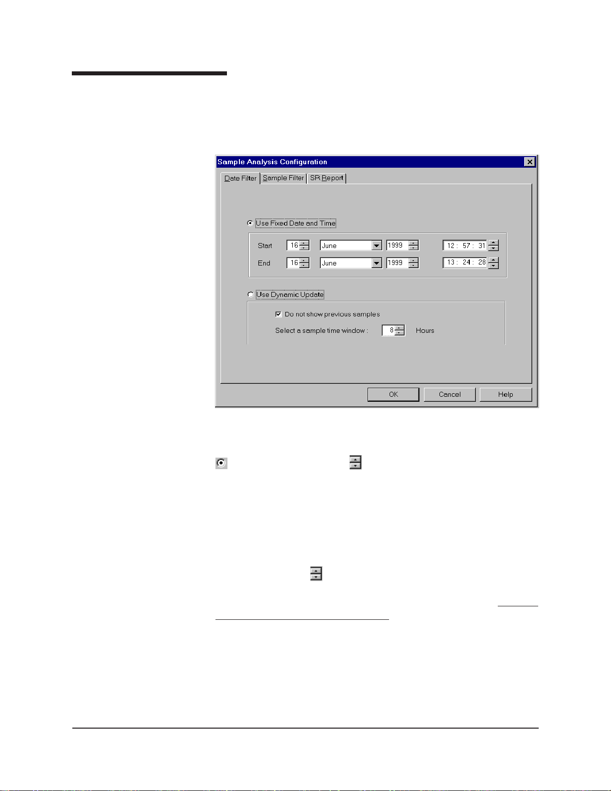
Using the date filter
Use the date filter to select date/time parameters for the analysis. To use
the date filter, click the Date Filter tab from the analysis configuration
window .
87
EXAMPLE
CANNON
®
miniPV-Series Automatic Viscometer with VISCPRO® Instruction & Operation Manual
T o define a Fixed Date and T ime, click the corresponding radio button
. Then use the spin controls and/or list box selection options to set
the appropriate date/time parameters. All samples tested after the start
date/time and before the end date/time, inclusive, will be included.
To automatically update the report with sample data as tests are completed, click the Use Dynamic Update radio button. Click the Do not
show previous samples box if you do not wish to display samples run
prior to the time the analysis is opened.
Use the spin controls
to select the Sample Time Window (the desired
range of recent samples to be included in the analysis). Data from
samples tested within [x] hours will be displayed in the analysis.
the analysis sorting options are disabled if you are using Dynamic
Update.
If the Do not show previous samples box was unchecked and a Sample
Time Window value of 5 hours was selected, the analysis (when opened)
would display data for all samples tested within the last five hours.
Version 1.a— January, 2011; CANNON
2139 High Tech Road • State College, PA 16803 • USA
®
Instrument Company
Note that
Page 94

88
Using the sample filter
Use the sample filter to limit the analysis to samples which have been
tested on certain instruments and tubes, or which have certain Sample ID
characteristics.
T o filter samples by instrument, tube serial number (S/N) or Sample ID,
click the Sample Filter tab from the analysis configuration window.
CANNON
Some (not all) analyses offer an option to display data for samples which
did not complete successfully. Click the Display Unsuccessful
Samples box if you wish to use this data. Unsuccessful samples, which
have no flow time, will be listed with a kinematic viscosity value of “0”.
Then select the desired instruments and tubes from their respective list
boxes. To select a range of tubes/instruments, click on the first desired
item and then hold down the S key while clicking on the last
desired item in the sequence. T o individually select tubes/instruments
from the list boxes and add them to the analysis, hold down the C key
while clicking on each desired tube/instrument.
T o filter by Sample ID characteristics, place the pointer/cursor in the
Sample ID field and type the desired sample IDs, or leave the field blank
to include all sample IDs for the selected instruments/tubes. You may use
wildcards (%,_) to select a range of samples. For example, S% would
®
miniPV®-HX Automatic Viscometer with VISCPRO® Instruction & Operation Manual
Version 1.0— January , 2011; CANNON
2139 High Tech Road • State College, PA 16803 • USA
®
Instrument Company
Page 95

include data from all samples starting with S. %S% would include data
from all samples containing S. The underscore (_) is a single-character
wildcard.
You may use multiple IDs separated by a comma. For example,
AV%,40C% would display all samples beginning with AV or 40C.
89
NOTE
If no instruments/tubes/Sample IDs are selected, the analysis will display
data for ALL instruments/tubes/Sample IDs.
Using the report/port output filter
Use the Report or Port Output filter to determine which data will be
calculated and/or included in the analysis, and/or in what sequence that
data will be displayed. Report/Port Output filter options will vary
depending on the nature of the analysis. For more information on Report/
Port Output filter options, please see the chapter on the specific analysis.
Reconfiguring a displayed analysis
An on-screen analysis may be reconfigured using the same filtering tools
available when creating a new configuration. To access configuration
options for a displayed analysis:
1. Select Analyses from the VISCPRO
2. Select Configure Analysis from the Analyses options.
3. Select the desired analysis from the available analyses. The Sample
Analysis Configuration window will appear .
4. Reconfigure the analysis as desired by clicking the tabs to access the
Date, Sample and Report filtering options (see previous sections).
When done, click OK.
®
primary menu options.
5. You will be prompted to save the new analysis configuration. After
you make your selection(s), the analysis will be performed and
displayed using the new configuration settings.
Resizing table columns
T o resize columns from a displayed analysis for easier viewing/printing,
move your mouse pointer/cursor to the edge of the desired column
heading. The mouse pointer will change to a bi-dimensional arrow .
Click and drag the edge of the heading to the new location and then
release the mouse button. The entire column will be resized as you drag.
User column size settings will be maintained as long as the analysis
window is open.
CANNON
®
miniPV-Series Automatic Viscometer with VISCPRO® Instruction & Operation Manual
Version 1.a— January, 2011; CANNON
2139 High Tech Road • State College, PA 16803 • USA
®
Instrument Company
Page 96

90
Saving a current analysis
T o save a current analysis configuration:
1. Select Analyses from the VISCPRO
2. Select Save Analysis from the Analyses menu options.
3. Select the desired analysis. The Save Configuration window will
appear. Type the name of the new configuration in the Save As:
field. Or double-click the name of a preexisting configuration in the
Existing Configurations list box to replace the existing configuration
with the new configuration settings.
4. Click OK.
®
primary menu options.
NOTE
You may click Cancel from the Save Configuration window to exit without
saving configuration changes.
Deleting an analysis configuration
You can delete an existing analysis configuration from the Choose
Analysis window by highlighting the desired configuration in the list box
and clicking the Delete button or pressing the D key . The configuration will be immediately and permanently deleted.
Printing an analysis
To print the complete analysis, select Print from the VISCPRO® Main
menu while the analysis is being displayed. If multiple VISCPRO
windows are open, click the analysis window for the analysis you want to
print to make it the active window before you select Print. Then choose
print options from the Windows® Print window and click OK to print the
analysis. (Consult your W indows® manual and printer/print driver documentation for more information on print settings).
It is also possible to select individual or multiple samples from an analysis
for printing (see next section).
®
NOTES
CANNON
The font size for printed analyses will be automatically adjusted to fit data
columns to the selected printer paper size. If the font is too small, or if
columns of data are missing or truncated, try using print options to set
your printer to print in landscape instead of portrait orientation.
The Print option from Main will not be accessible unless the analysis
window is the active window.
®
miniPV®-HX Automatic Viscometer with VISCPRO® Instruction & Operation Manual
Version 1.0— January , 2011; CANNON
2139 High Tech Road • State College, PA 16803 • USA
®
Instrument Company
Page 97

Keystrokes for selecting data for printing
You can print data for a selected sample or samples from an on-screen
analysis by highlighting the desired sample data and then using the Print
option from the VISCPRO
To select data for a single sample, click on the line of data associated
with the sample on the screen display . To print a sequential range of
samples, highlight the first sample in the range, then hold down the
S key and click on the last sample in the range. To individually
select test data from the on-screen list box for printing, hold down the
C key while clicking on each desired entry.
When all desired data has been selected, click on Print from the Main
menu. Make certain that the Selection radio button
from the Print range options. Then click OK to print to the selected printer .
Exporting analysis data
The data export analyses included with the VISCPRO® software provide
a convenient method for outputting sample data to laboratory collection
systems or to an ASCII file.
®
Main Menu.
91
has been selected
There are three different data export analyses. For step-by-step instructions on exporting data from the VISCPRO
®
database, consult the
manual chapter on the specific analysis:
Error Data Export—Chapter 11 (export of error information)
Sample Data Export—Chapter 9 (export of sample information)
VI Data Export—Chapter 10 (export of sample/VI information)
Once the data has been exported, it can be manipulated using database/
spreadsheet software packages such as Excel
Pro®. These packages provide additional tools for configuration of report
data for such functions as:
®
, Access® or Quattro
Statistical Process Control
Long-term Monitoring of Daily Check Standards
CANNON
®
miniPV-Series Automatic Viscometer with VISCPRO® Instruction & Operation Manual
Version 1.a— January, 2011; CANNON
2139 High Tech Road • State College, PA 16803 • USA
®
Instrument Company
Page 98

92
This page intentionally left blank.
CANNON
®
miniPV®-HX Automatic Viscometer with VISCPRO® Instruction & Operation Manual
Version 1.0— January , 2011; CANNON
®
Instrument Company
2139 High Tech Road • State College, PA 16803 • USA
Page 99

CHAPTER
93
7
CAV DATA TABLE
The CAV sample analysis is designed to permit convenient viewing of
data collected from samples which have been tested using the Measure
Sample Viscosity sample action option.
The sample analysis displays sample data in a tabular format. In addition
to Sample identification (ID), the following data may be included:
INV—Invalid test indication (flow time out of tolerance)
Tol[erance]—Acceptable difference in multiple test results for the
same sample
Date—Date the sample was measured
Time—Time the sample was measured
Tube S/N—Tube serial number (from Instrument Settings)
Tray [Index]—Position of the sample tray in the numeric sequence
(left to right)
Smple Indx.—Position of the sample in the sample tray
Bulb No.—Bulb number (the bulb in which the sample was run—#1
is the bottom bulb)
Technician—The technician logged on to VISCPRO at the test time
Instrument Type—Instrument type (CAV, CCS, etc.)
Instrument ID—Instrument Identification (from Instrument Settings)
KV—A verage kinematic viscosity (calculated from flow times)
Known KV—Known kinematic viscosity of the viscosity standard
% Diff KV—Percent difference between the measured KV and the
known KV for viscosity standards
Temp[erature]—Average bath temperature
T1-T4—Bath temperature during each sample drop
% Diff —For multi-drop samples: ((maximum drop time - minimum
drop time) / average drop time) * 100
EXAMPLE: Four drop times: 80.3, 80.4, 80.5, 80.5
CANNON
Maximum drop time = 80.5
Minimum drop time = 80.3
((80.5 - 80.3)/80.425) * 100 = 0.2487
Abs. Diff —For multi-drop samples: maximum drop time - minimum
drop time
EXAMPLE: Four drop times: 80.3, 80.4, 80.5, 80.5
Maximum drop time = 80.5
Minimum drop time = 80.3
(80.5 - 80.3) = 0.2
®
miniAV®-HX Automatic Viscometer with VISCPRO® Instruction & Operation Manual
Version 1.0— January, 2011; CANNON
2139 High Tech Road • State College, PA 16803 • USA
®
Instrument Company
Page 100

94
{1,10} Efflux%—For multi-drop samples: displays the first 10 sample
efflux times
{1,20} Efflux%—For multi-drop samples: displays the first 20 sample
efflux times
Avg Efflux%—The average efflux time for efflux values used for
viscosity calculation
C, E—The calibration constants used for this determination
SUS—Saybolt Furol Seconds calculation
% KE—Percent contribution of the kinetic energy correction to the
measured viscosity.
Reporting options
Configuring the CAV Data Table
The CAV Data Table analysis can present all or any of the above data
for samples residing in the database. Several powerful filters may be used
to create useful reports. These filters may be used by making selections
from the tabbed property sheets found in the Sample Analysis Configu-
ration window. Once the appropriate filters have been designated, the
resulting report configuration can be saved for future use.
For general information on using analyses, see Chapter 6. To access and
configure the CAV Data Table, follow the procedure below:
1. Select Analyses from the VISCPRO
®
primary menu options.
2. Select View Analysis ... from the Analyses menu. The Choose
Analysis window will appear.
3. Double-click Basic Package from the list of Available Analysis
Packages.
4. Select CAV Data Table from the Basic Package report options.
The Choose Analysis window
CANNON
®
miniPV®-HX Automatic Viscometer with VISCPRO® Instruction & Operation Manual
Version 1.0— January , 2011; CANNON
2139 High Tech Road • State College, PA 16803 • USA
®
Instrument Company
 Loading...