

Page 1

CONTENTS
i
1
2
3
INTRODUCTION 1
Overview ............................................................................................................................. 1
Specifications ....................................................................................................................... 2
Safety warnings .................................................................................................................... 3
Safety features ...................................................................................................................... 4
Operator safety .................................................................................................................... 4
UNPACKING AND ASSEMBLY 5
Unpacking the CT -500 ......................................................................................................... 5
Assembly ............................................................................................................................. 6
CT -500 Series motor-stirrer installation..................................................................... 8
CT -600 TE cooler and motor-stirrer installation......................................................... 8
Final assembly ........................................................................................................ 11
Inserting viscometer tubes/thermometers.............................................................................. 11
Filling the bath .................................................................................................................... 12
Draining the bath................................................................................................................. 12
CT-500 OPERATION 13
4
Front panel ......................................................................................................................... 13
Turning on the CT -500........................................................................................................ 14
Setting the temperature ....................................................................................................... 14
Pre-set temperature selection .................................................................................. 14
Adjusting the High T emperature Limit Control ......................................................... 15
Custom temperature selection ................................................................................. 15
Adjusting the High T emperature Limit Control ......................................................... 16
V erifying Limit Control operation ......................................................................................... 17
Cleaning ............................................................................................................................. 17
Using the thermoelectric cooling system (CT -600 only) ........................................................ 17
WARRANTY/RETURN INFORMATION 19
Products limited warranty.................................................................................................... 19
Reagent and chemical warranty ........................................................................................... 19
Returning a product to CANNON®.................................................................................... 20
®
CANNONCANNON
CANNON
CANNONCANNON
CT-500/600 Series II CONSTANT TEMPERATURE BATH
Version 3..2—March, 2012;
2139 High Tech Road • State College, PA • 16803 • USA
CANNONCANNON
CANNON
CANNONCANNON
®
Instrument Company
Page 2

ii
A
B
C
D
APPENDIX A — PROBLEM ANALYSIS 21
APPENDIX B — REPLACEMENT PARTS LIST 23
APPENDIX C —THERMOMETRY FOR THE CT-500 25
Kinematic viscosity and temperature.................................................................................... 25
APPENDIX D — CHOOSING A BATH LIQUID 27
®
CANNONCANNON
CANNON
CANNONCANNON
CT-500/600 Series II CONSTANT TEMPERATURE BATH
Version 3..3—March, 2012;
2139 High Tech Road • State College, PA • 16803 • USA
CANNONCANNON
CANNON
CANNONCANNON
®
Instrument Company
Page 3
CHAPTER
1
Overview
1
INTRODUCTION
Manual
CT-500 function
Effective temperature range
Precision
Temperature selection
This manual is intended to provide information on the installation, characteristics and operation of the CANNON
T emperature Baths. CT-500 references in the manual will apply to all
models unless otherwise indicated.
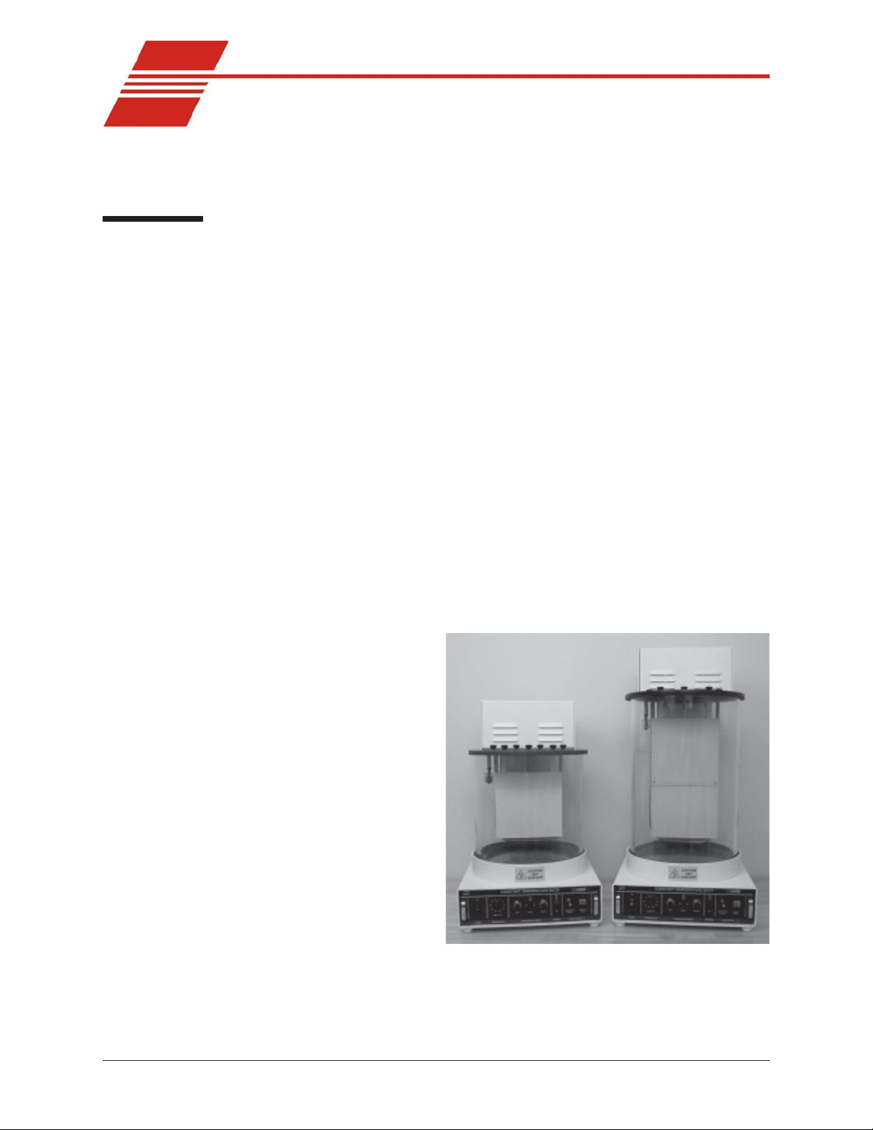
The CANNON® CT-500 series II Constant Temperature Baths are
designed to be used for precise viscosity measurements. Because of its
temperature stability and ease of use, the baths are also suitable for many
other applications where temperatures must be maintained within
± 0.01 °C.
The CANNON® CT-500 will maintain temperatures of 20°C to 100°C
± 0.01°C. The CT-500 includes a built-in cooling coil which, when
connected to tap water or a cooling system, permits operation below or
slightly above ambient temperature. The cooling coil should be used
when controlling temperature within 10°C of ambient.
The precision of kinematic viscosity measurements possible with the CT500 system meets the sensitivity requirements of ASTM D 445.
Ten of the most
commonly-used
temperatures for
kinematic viscosity
measurement can
be set using the
left-hand dial on
the bath front
panel. The bath
will equilibrate
within a fraction of
one degree of the
desired temperature. A fine-tuning
control permits
further temperature adjustments.
By switching to
the variable setting
on the front panel,
the operator can set any temperature within the operating range of the
instrument.
Figure 1: The CT-500/518 Series II instrument
®
CT-500/600 series II Constant
s
®
CANNONCANNON
CANNON
CANNONCANNON
CT-500/600 Series II CONSTANT TEMPERATURE BATH
Version 3..3—March, 2012;
2139 High Tech Road • State College, PA • 16803 • USA
CANNONCANNON
CANNON
CANNONCANNON
®
Instrument Company
Page 4

2
Bath description
Specifications
ledoMtnemurtsnI
snoisnemiD ediwmm704
thgieW .lcni)sbl46(gk1.92
thgieWgnippihS .lcni)sbl19(gk4.14
yticapaChtaB )lag5(L22)lag7(L03)lag9(L83)lag5(L22
egnaR.pmeThtaB C°001-C°02
ytilibatS.pmeThtaB *C°10.0±
snoitidnoCgnitarepO IIyrogetacnoitallatsnI;gnisnednoc-nonHR%09-%01,C°03-C°51
tnemecalpeResuF "¼x"¼1;V052A21M
ecnailpmoC )CEE/32/37(evitceridegatlovwoL;)CEE/633/98(evitceridCME
/rebmuNgolataC
stnemeriuqeRlacirtcelE
The bath chamber is a cylindrical clear Pyrex® vessel 300 mm (12
inches) in diameter and 300 mm (12 inches) high. A stainless steel baffle
coated with white PTFE is located in the center of the bath and provides
a convenient backdrop for viewing viscometers placed in the bath. The
top cover contains seven round holes 51 mm (two inches) in diameter for
insertion of viscometer holders. An additional 10 mm (3/8 inch) hole is
provided for a thermometer.
A solid-state control circuit provides proportional control of the temperature. The sensing element for the control circuit is a stainless steelencased thermistor. The entire electrical control system is located in a
drawer beneath the bath.
SNOITACIFICEPSTNEMURTSNI
005-TC 815-TC 425-TC 006-TC
peedmm263
hgihmm016
)ni42x52.41x61(
rajhtab
rajhtab
005-TC 815-TC 425-TC 006-TC
01A-6279
%01±CAV511
sttaw
sttaw
0001,zH06/05
51A-6279
%01±CAV032
0001,zH06/05
ediwmm704
peedmm263
hgihmm267
)ni03x52.41x61(
rajhtab
rajhtab
71A-6279
91A-6279
retaergrom/V2fodleifFRnafoecneserpehtniC°1.0otesaercedyamytilibatshtaB*
.lcni)sbl07(gk8.13
.lcni)sbl99(gk54
%01±CAV511
sttaw0031,zH06/05
%01±CAV032
sttaw0031,zH06/05
ediwmm704
peedmm263
hgihmm419
)ni63x52.41x61(
rajhtab
rajhtab
2eergednoitulloP
.lcni)sbl67(gk5.43
raj
.lcni)sbl701(gk6.84
raj
).ces06,CDV0091(TOP-IH
%01±CAV511
sttaw0031,zH06/05
%01±CAV032
sttaw0031,zH06/05
hgihmm838
03A-6279
53A-6279
ediwmm704
peedmm914
)ni33x5.61x61(
htab.lcni)sbl87(gk4.53
htab.lcni)sbl801(gk94
%01±CAV511
sttaw0001,zH06/05
%01±CAV032
sttaw0001,zH06/05
®
CANNONCANNON
CANNON
CANNONCANNON
CT-500/600 Series II CONSTANT TEMPERATURE BATH
Version 3..2—March, 2007;
CANNONCANNON
CANNON
CANNONCANNON
®
Instrument Company
2139 High Tech Road • State College, PA • 16803 • USA
Page 5

Safety warnings
Please observe the following safety procedures and notices for proper
operation of your CT-500 series II Constant Temperature Bath:
• Make sure that your unit is operated only by qualified personnel
• Make sure that you read and understand all operating instructions
and safety precautions listed in this manual before installing or
operating your unit. If you have questions regarding instrument
operation or documentation, contact CANNON
®
Instrument Com-
pany.
• Deviation from the installation, operation or maintenance procedures
described in this manual may result in a hazardous situation and may
void the manufacturer's warranty.
• Transport the unit with care. Sudden jolts or drops may cause
damage to components.
• Observe all warning labels.
• Never remove warning labels.
3
General Caution
• Never operate damaged or leaking equipment.
• Never operate the unit without appropriate levels of approved bath
fluid in the bath.
• Do not add bath fluid to the bath unless the bath temperature is
within 10°C of ambient.
• Do not splash liquids on the external surfaces of the CT-500, including the Pyrex
®
bath jar.
• Do not obstruct the cooling vent on the top of the CT-500.
• Always turn off the unit and disconnect the mains cable from the
power source before performing service or maintenance procedures,
or before moving the unit.
• Always empty the bath before moving the unit.
• Never operate the equipment with damaged mains power cables.
• Refer all service and repairs to qualified personnel.
In addition to the warnings listed above, additional cautions are posted
throughout the manual. These warnings may be designated by an appropriate symbol inside an equilateral triangle. General cautions are indicated with an exclamation point (see diagram, left). Read and follow
these important instructions. Failure to observe these instructions can
result in permanent damage to the unit, significant property damage,
personal injury or death.
Hot surface cautions (see diagram, left) may be attached on or near hot
surfaces of the CT-500. Avoid touching these surfaces when running the
bath at temperatures above 50°C.
®
CANNONCANNON
CANNON
CANNONCANNON
CT-500/600 Series II CONSTANT TEMPERATURE BATH
Version 3..2—March, 2007;
2139 High Tech Road • State College, PA • 16803 • USA
CANNONCANNON
CANNON
CANNONCANNON
®
Instrument Company
Page 6

4
Safety features
The CT-500 comes equipped with a number of safety features:
Temperature fault sensor
Thermistor cutoff detection
Bath fluid level cutoff
NOTE
Operator safety
A second thermistor in the temperature bath senses any over-temperature
fault condition. If such a condition occurs, all power is removed from the
bath until an operator corrects the problem and resets the over-temperature limit circuit.
If the control thermistor is disconnected, all power to the bath heaters is
cut off.
The CT-500 will not operate if the liquid level in the bath is too low. If
such a condition occurs, all power is removed from the bath until the
liquid level in the bath is restored to the minimum safe level.
Safety devices may be impaired if equipment is not operated per manual
instructions.
All technicians who use the CT-500 should follow these basic safety
procedures:
• The CT-500 power cord should only be connected to a suitable AC
mains power source (with protective earth ground) matching the
specifications of the S/N label on the CT-500 rear panel.
• The CT-500 should be placed on a stable laboratory table or bench.
• If any liquids are spilled in or around any electronic components of
the CT-500, remove power and contact CANNON
®
Instrument
Company before introducing power to the system again.
• Position power cords so that they are not likely to be walked on or
pinched by items placed on or against them. Keep all connections as
neat as possible.
• To disconnect the power cord, pull it out by the plug. Never pull the
cord itself.
• Do not attempt to service the CT-500 system by removing panels and
trying to effect repairs. Contact CANNON
®
Instrument Company for
all service and repair needs.
• Monitor bath fluid level carefully and use caution when operating at
temperature set points above ambient temperature. Liquid may
expand and overflow the jar.
• Observe appropriate safety precautions when handling bath fluid
(refer to the Material Safety Data Sheet included with the bath fluid
for more details.)
CAUTION
CANNONCANNON
CANNON
CANNONCANNON
Version 3..3—March, 2012;
Never use flammable bath liquids in any CT -500 bath.
®
CT-500/600 Series II CONSTANT TEMPERATURE BATH
2139 High Tech Road • State College, PA • 16803 • USA
CANNONCANNON
CANNON
CANNONCANNON
®
Instrument Company
Page 7
CHAPTER
UNPACKING AND ASSEMBLY
2
Unpacking the CT-500
5
Damaged items
CAUTION
Some CT -500 component s, including the glass jar and the primary
instrument housing, are quite heavy . It is recommended that two people
carry the shipping cartons and the heavier unpacked components.
When lifting the CT-500 bath, do not grasp the handles of the electrical
drawer. Drawer handles are not designed to bear the weight of the
instrument.
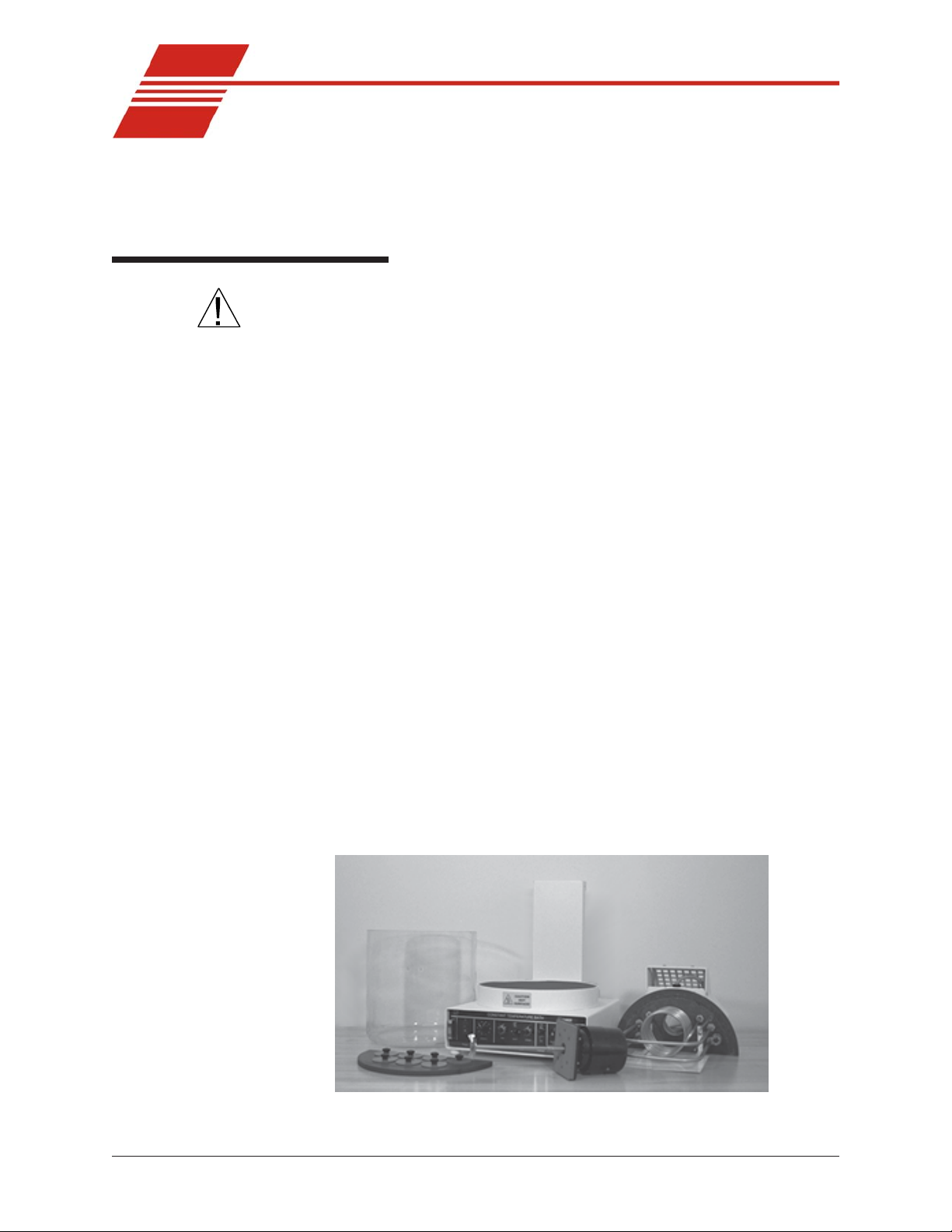
1. Remove all components from the shipping container(s).
2. Remove any and all packing materials (styrofoam, etc.) from the
components.
3. Verify reception of shipped materials by comparing equipment items
with packing/parts list(s). Report missing items to CANNON
Instrument Company immediately.
4. Inspect each component for signs of damage. Report damages to the
shipper and CANNON
Retain all packing materials until the instrument is connected and
functioning properly. If any component(s) must be returned to
CANNON® Instrument Company , the damaged item(s) should be pack-
aged in the original shipping container. Refer to the final chapter of this
manual for instructions on returning defective equipment. Customers
outside the United States should contact the local CANNON® agent for
procedures on returning products to CANNON® .
®
Instrument Company immediately .
®
Figure 2: CT-500 primary components
®
CANNONCANNON
CANNON
CANNONCANNON
CT-500/600 Series II CONSTANT TEMPERATURE BATH
Version 3..3—March, 2012;
2139 High Tech Road • State College, PA • 16803 • USA
CANNONCANNON
CANNON
CANNONCANNON
®
Instrument Company
Page 8
6
Assembly
Instrument placement
CAUTION
Minimum clearance
Support/insulation
Felt pad placement
Bath jar placement
1. Place the bath control housing in the space that it will occupy when
the bath is operable. This should be a sturdy, level tabletop or bench
with a non-flammable surface.
Be careful when lifting the control housing; it is quite heavy .
The CT-500 series II bath requires 25 cm (10") of clearance to the
rear and sides of the unit.
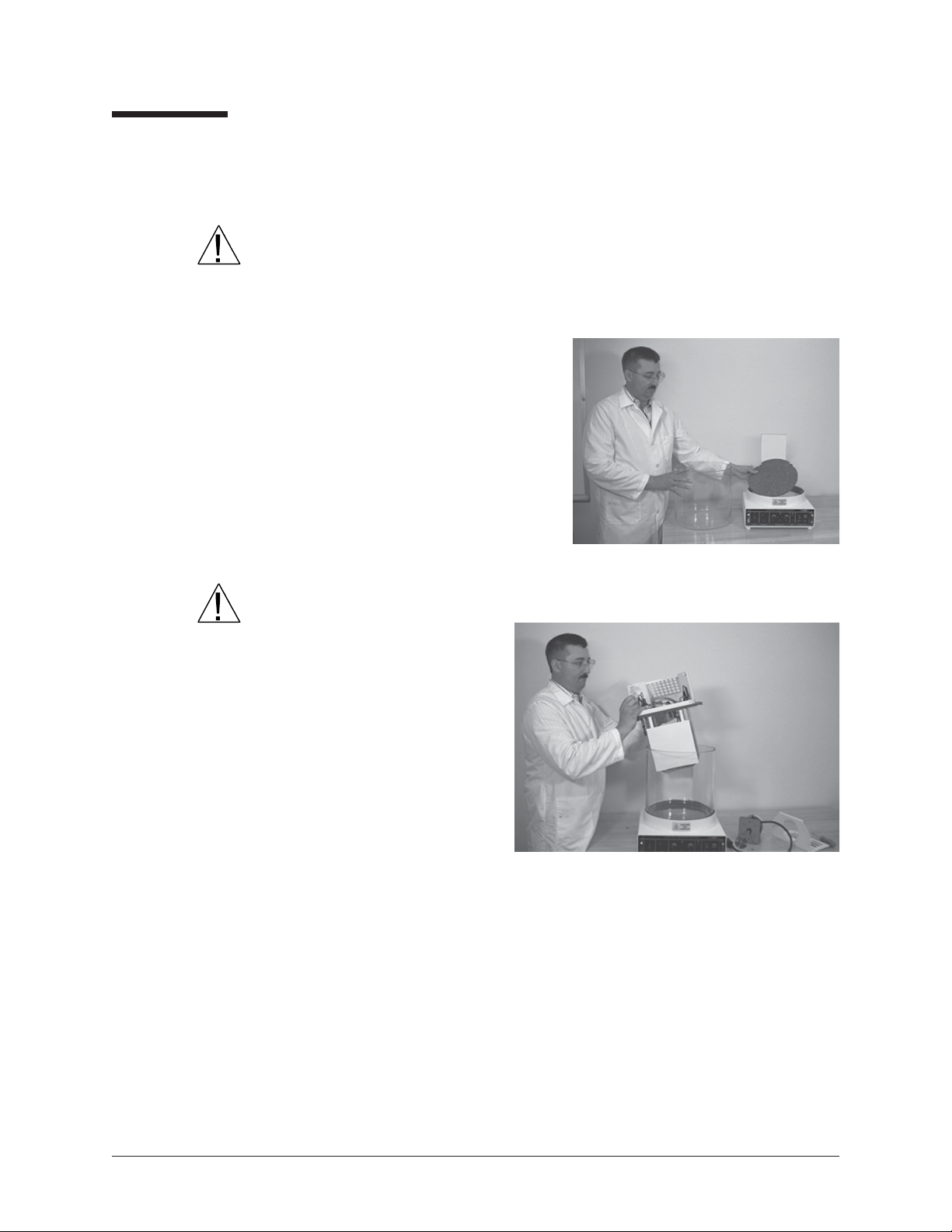
2. The CT -600 will require
two felt pads. The CT-500
will require one felt pad.
3. Place the felt pad(s) on top
of the insulating disk (see
Figure 3).
4. Place the glass bath jar on
top of the felt pad(s).
Figure 3: Placing the felt pad(s)
on the insulating disk
CAUTION
Be careful when lifting
the bath jar; it is quite
heavy .
5. Position the rear
cover containing
the motor housing,
heaters, cooling
coil, and baffle on
top of the jar (see
Figure 4), feeding
all connecting
cables from the
heaters, float
Figure 4: Positioning the rear cover
switch and control/overtemp probes through the vertical wiring
channel in the rear of the housing. The back of the motor housing
should fit over the vertical channel, and the groove on the underside
of the half-round cover should fit over the edge of the jar.
6. Place the front bath cover (with holes for the viscometers) on top of
the front half of the jar.
6b. CT-600 ONLY: Check for alignment of the the tab slots in the rear
housing with the screw holes in the vertical channel. If the alignment
is not correct, adjust the height of the bath vessel per steps 6c-6g.
®
CANNONCANNON
CANNON
CANNONCANNON
CT-500/600 Series II CONSTANT TEMPERATURE BATH
Version 3..2—March, 2007;
2139 High Tech Road • State College, PA • 16803 • USA
CANNONCANNON
CANNON
CANNONCANNON
®
Instrument Company
Page 9
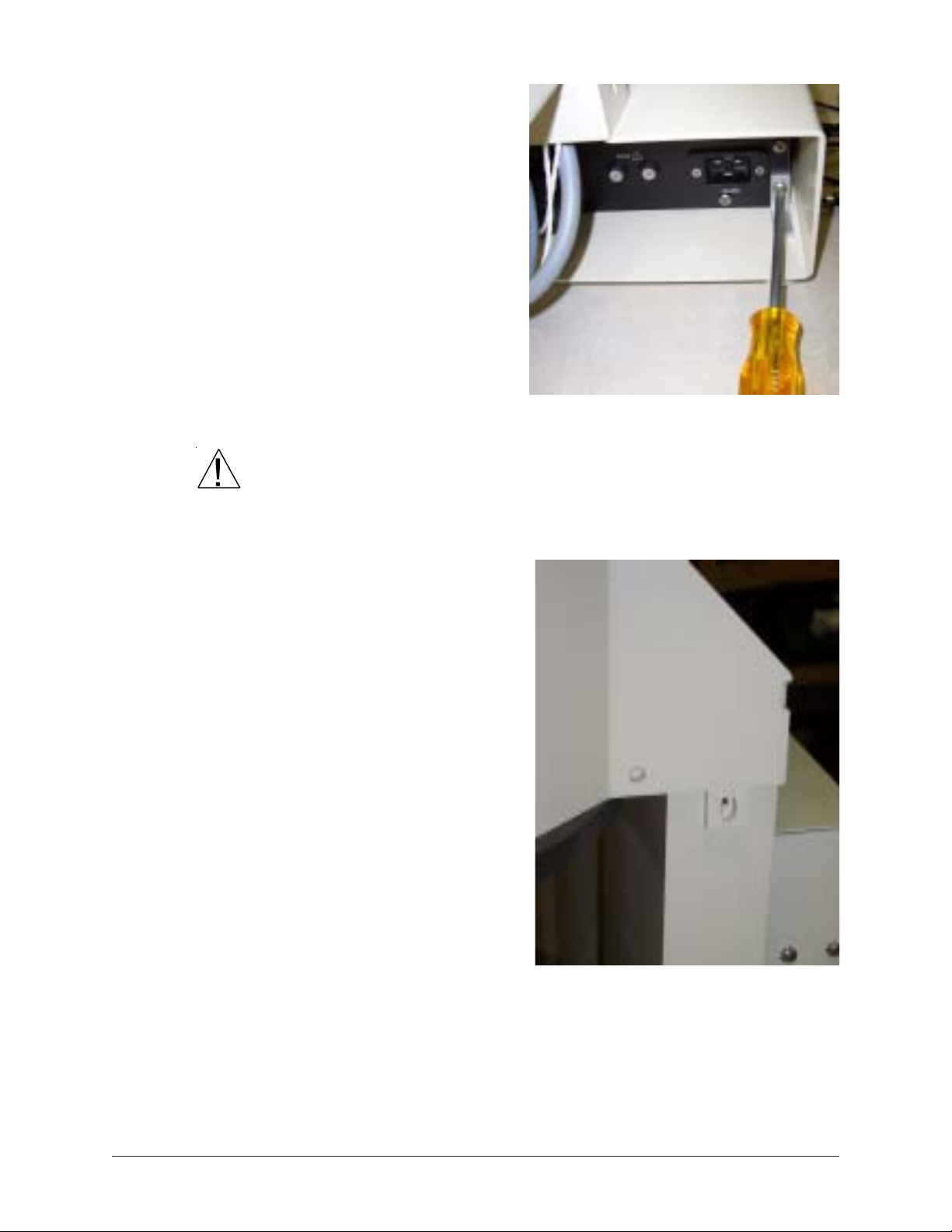
6c. Loosen and remove
the two Phillipshead screws
securing the drawer
unit to the brackets
inside the drawer
housing (see Figure
4b).
6d. Pull out the electri-
cal drawer using the
handles provided,
disconnecting the
two connection
cables as you do so.
7
Figure 4b: Removing drawer screws
CAUTION
If it is plugged in, unplug the AC line (power) cord before you remove the
drawer!
6e. Pull the drawer completely free of the housing and set it aside.
6f. When the drawer is
removed, locate the
four 1/4-20 socket
head cap screws
visible at the top of
the drawer opening
underneath the bath.
6g. Using the Allen
wrench provided,
adjust the cap screws
until the bath top is
level and the tab slots
in the rear housing
are aligned with the
screw holes in the
vertical channel (see
Figure 4c). Then
replace the bath
drawer and secure it
using the Philips-head
screws previously
Figure 4c: tab slots properly aligned with
vertical channel screw holes
removed.
®
CANNONCANNON
CANNON
CANNONCANNON
CT-500/600 Series II CONSTANT TEMPERATURE BATH
Version 3..2—March, 2007;
2139 High Tech Road • State College, PA • 16803 • USA
CANNONCANNON
CANNON
CANNONCANNON
®
Instrument Company
Page 10

8
CT-500 Series motor-stirrer installation
Motor-stirrer installation
NOTE
CAUTION
NOTE
T o install the motor-stirrer , follow the procedure below .
If you have the CT -600 Series instrument, skip to the CT-600 Series
installation section and complete the installation directions in place of this
section.
7. Remove the screws that fasten the top cover to the motor housing
and remove the top cover.
8. Remove the motor-stirrer from its box.
Use care when handling the motor shaft and impeller to prevent damaging
sensitive components. Do NOT hold the motor assembly by the shaft.
Doing so could bend the rotor shaft slightly out of alignment.
T wo standoffs, one on each side of the opening for the motor-stirrer , serve
as locating pins for the motor support pad. The holes in the pad fit loosely
over these standoffs to prevent the motor from vibrating out of position.
9. Carefully slide the motor-stirrer into place on the motor support pad,
impeller shaft down, and align the motor line cord so it points toward
the rear of the bath (see
Figure 5). The motor-stirrer
should now lie flat on the top
of the bath.
10. Lower the motor-stirrer
power cord down through
the vertical channel in the
rear of the unit.
11. Attach the top cover,
making sure that all cords
pass through the rear
opening and down through the
vertical shaft. Secure the front of the cover first. The two longer
screws w/toothed washers from the Accessories Kit are used to
secure the housing to the sides the vertical shaft.
CT-600 TE cooler and motor-stirrer installation
This section of the installation procedure is for the CT -600 bath only.
The CT -600 is shipped with the top housing sections installed, but with the
motor-stirrer and TE cooling unit packaged separately. To complete CT600 installation you will remove the housing sections, install the motorstirrer and TE cooling unit, and reassemble the housing. Follow the
procedure below to install these components.
Figure 5: Positioning motor-stirrer
®
CANNONCANNON
CANNON
CANNONCANNON
CT-500/600 Series II CONSTANT TEMPERATURE BATH
Version 3..2—March, 2007;
2139 High Tech Road • State College, PA • 16803 • USA
CANNONCANNON
CANNON
CANNONCANNON
®
Instrument Company
Page 11

Figure 5a: Removing top rear housing
9
1. Remove the two screws securing the rear housing to
the bath chassis (see Figure 5a). Set the screws
aside.
2. Loosen but DO NOT REMOVE the two top screws
securing the front housing (see Figure 5b). This will
provide play for removal of the rear housing.
3. Remove the rear housing by sliding it backward
away from the bath.
4. Remove the screws securing the front housing to the
bath chassis.
5. Remove the front housing.
6. Uncoil the cables from the heaters, float switch and
control/overtemp probes, then lower the ends of the
cables through the vertical channel at the rear of the
bath.
7. Install the thermoelectric cooler by sliding it through
the circular 2" aperture that will be enclosed by the
housing (see Figure 5c).
Figure 5b: Removing top rear housing
CAUTION
Make certain that the tabs (see Figure 5d, next page) are
oriented so that they will clear the edges of the
aperture during installation.
8. Tighten the two tab screws (one on each side of the
finned tube). During tightening the tabs will orient
and seat against the bottom of the bath cover to
secure the themoelectric cooler to the bath cover
(see Figure 5e).
9. Attach the two matching white power supply
connectors together (see Figure 5f).
10. Attach the two matching black power supply
connectors together (see Figure 5g).
1 1. Carefully slide the motor-stirrer into place on the
motor support pad, impeller shaft down (see Figure
5, previous section) with "cut out" portion corresponding to the location of the TE cooler .
12. Make certain to align the motor line cord so it points
toward the rear of the bath. The motor-stirrer should
now lie flat on the top of the bath.
Figure 5c: Inserting the TE cooler
®
CANNONCANNON
CANNON
CANNONCANNON
CT-500/600 Series II CONSTANT TEMPERATURE BATH
Version 3..2—March, 2007;
2139 High Tech Road • State College, PA • 16803 • USA
13. Lower the motor-stirrer power cord down through
the vertical channel in the rear of the unit.
®
CANNONCANNON
CANNON
CANNONCANNON
Instrument Company
Page 12

10
14. Loosely install the front
housing using the screws
previously removed, but do
not yet tighten the screws.
15. Install the rear housing by
sliding the front flanges
forward under the front
housing until the two pieces
mate. If there is insufficient
play , loosen the front housing
screws until the flanges can
slide into place.
16. Secure the rear housing
using the two screws
previously removed (see
Figure 5h, below).
17. Obtain two additional screws
and toothed washers from
the Accessories Kit. Install
the screws to the tabs at the
rear of the front housing to
secure the housing to the
vertical channel.
Figure 5d: TE cooler mounting tabs
18. Tighten all housing screws to
complete the housing
installation.
Figure 5e: Securing mounting tabs
Figure 5f: Connecting TE power
Figure 5h: Installing rear housing
®
CANNONCANNON
CANNON
CANNONCANNON
CT-500/600 Series II CONSTANT TEMPERATURE BATH
Version 3..2—March, 2007;
2139 High Tech Road • State College, PA • 16803 • USA
CANNONCANNON
CANNON
CANNONCANNON
Figure 5g: Connecting power
®
Instrument Company
Page 13

Final assembly
Connect all remaining plugs and probes to the correspondingly labeled
and/or color-coded sockets at the rear of the CT-500 bath unit.
(see Figure 6)
Figure 6: CT-500 rear panel connections. All connections marked with " " contain potentially
hazardous voltages. These sockets are for connection to CT-500 plugs ONLY (see below).
Rear Panel Connections:
Control Thermistor — Connects main temperature control thermistor to the Control Unit
Float Switch — Connects the fluid-level sensor to the Control Unit
Over-temp. Thermistor — Connects over-temp. thermistor to the Control Unit
Heaters — Supplies AC Mains power to the bath heaters
Stirrer — Supplies AC Mains power to the motor-stirrer
Fuses — Protects against damage or hazard in the event of an internal fault
Mains — Provides AC mains power entry connection
11
CAUTION
The CT -500 power cord must be connected to an AC mains source
matching the specifications of the S/N label on the instrument rear panel.
Inserting viscometer tubes/thermometers
The top cover of the CT-500 contains seven apertures, 51 mm (2") in
diameter, for the insertion of viscometer tube holders. T wo additional
holes are provided for insertion of thermometers.
Inserting viscometer tubes
NOTE
Thermometer immersion
If necessary, remove the viscometer tube hole cover(s) from the top of
the bath and carefully place the viscometer tube(s), with the proper
holder attached, into the bath through the aperture(s) in the top cover.
After filling the bath with fluid, adjust the height of the viscometer tube(s)
to ensure that the liquid under test and/or any timing marks on the tube
are a minimum of 6 mm (¼") below the top level of the liquid.
Proper thermometer immersion is critical for viscosity measurements.
Even a calibrated thermometer will read incorrectly if is it improperly
immersed in the bath. “Total immersion” kinematic viscosity thermometers should be used with the bulb and only the mercury column beneath
the surface of the liquid, but with the emergent stem above the surface at
ambient temperatures.
®
CANNONCANNON
CANNON
CANNONCANNON
CT-500/600 Series II CONSTANT TEMPERATURE BATH
Version 3..2—March, 2007;
2139 High Tech Road • State College, PA • 16803 • USA
CANNONCANNON
CANNON
CANNONCANNON
®
Instrument Company
Page 14

12
NOTE
Filling the bath
Different thermometers have different immersion requirements. Refer to the
information included with the thermometer in use for specific instructions.
Make sure that the bath is placed in its intended final position before
adding bath fluid. The CT -500 should not be moved with bath fluid in the
bath jar. NEVER USE FLAMMABLE BATH LIQUIDS.
1. Make sure that the instrument power is OFF and select a bath liquid
appropriate to your operating temperature range (see APPENDIX D).
2. Fill the jar with bath liquid at ambient temperature to a level sufficient
to engage the float switch. This float permits bath operation when the
minimum amount of fluid has been added to the bath jar.
3. Continue to add fluid until the bath liquid level has risen to approximately 40 mm (1.5") of the top of the jar.
4. Turn the instrument power ON and incrementally heat the bath to
desired control temperature while monitoring the bath liquid level
carefully. The bath level must be 15-20 mm (approximately ½" to
¾") from the top of the jar at the control temperature. If it becomes
apparent that this liquid level will not be achieved, return the bath to
within 10°C of ambient, turn the instrument power OFF and add or
remove liquid as necessary .
CAUTION
WARNING
Draining the bath
5. Repeat step four until you have attained the proper bath liquid level at
the desired control temperature.
Different bath fluids expand at different rates. Do not overfill the bath!
Monitor the level of bath liquid closely when operating the CT-500 at
higher temperatures (80-100°C). The bath liquid will expand as the
temperature increases. The CT-500 bath jar is not designed to contain
liquid under pressure. If the bath is overfilled, liquid may overflow.
If it becomes necessary to drain the liquid from the bath, obtain a suitable
container to hold all of the liquid drained from the bath (approximately 22
liters—4.5 - 5 gallons for the CT -500; approximately 30 liters—7 gallons
for the CT -518, approximately 38 liters—9 gallons for the CT-524).
Make sure that the bath liquid is within 10°C of ambient temperature.
Then insert a tube into the bath chamber from the top opening and siphon
the liquid from the bath into a container positioned lower than the bath.
WARNING
CANNONCANNON
CANNON
CANNONCANNON
Version 3..2—March, 2007;
Always use a rubber bulb or similar device to apply suction to a tube
containing bath liquids.
®
CT-500/600 Series II CONSTANT TEMPERATURE BATH
2139 High Tech Road • State College, PA • 16803 • USA
CANNONCANNON
CANNON
CANNONCANNON
®
Instrument Company
Page 15

CHAPTER
3
Front panel
13
CT-500 OPERATION
The controls for the CT-500 are divided into 5 different “control areas”
on the front panel. Each corresponds with a major function of the bath.
)lenaptnorf(SAERALORTNOC005-TC
hctiwssihT
sedivorp
ehtotrewop
.htab
t
REWOP ERUTAREPMET ERUTAREPMET
Figure 7: CT-500 front panel
laidnoitcelessihT
kciuqstimrep
dradnatsfognittes
htabteserp
.serutarepme
ehtfonoitropsihT
ehtstimreplenap
elggototresu
dexifneewteb
elbairavdna
erutarepmet
.snoitcnuflortnoc
TSUJDA
sihT
na
.retaeh
hctiws
setavitca
lanoitidda
TAEHERP TIMIL
lortnocsihT
ehtstsujda
erutarepmet
sretemarap
efasrof
htab
.noitarepo
LORTNOC
In this manual, the control areas will be abbreviated as follows:
Power = P Temperature = T T emperature Adjust = TA Preheat = PH Limit Control = LC
The commands in those areas will be printed in bold uppercase type,
with the abbreviation preceding. For example, TA - FIXED refers to the
left-hand dial (marked FIXED) in the TEMPERA TURE ADJUST (TA)
section of the control panel.
®
CANNONCANNON
CANNON
CANNONCANNON
CT-500/600 Series II CONSTANT TEMPERATURE BATH
Version 3..3—March, 2012;
2139 High Tech Road • State College, PA • 16803 • USA
CANNONCANNON
CANNON
CANNONCANNON
®
Instrument Company
Page 16

14
Turning on the CT-500
NOTE
Temperature Adjust (TA) dials on the CT-500 are equipped with locks to
prevent accidental changing of dial settings. Push the lock up to release
the dial. When the dial has been set to the proper position, push the lock
down to re-lock the dial.
1. Verify that the CT-500 has been assembled and installed correctly
(Chapter 2, Unpacking and Assembly).
2. Turn the bath Power switch on. Remember that the bath heaters will
not be activated if there is insufficient liquid in the bath.
NOTE
Initially the Limit Control (LC - TEMPERATURE ADJUST) dial must be
turned completely clockwise to enable the bath to heat properly . Af ter the
bath reaches operating temperature, this dial should be reset to prevent
the bath from overheating (see page 1 1).
3. Move the TA - SELECT switch to the left (fixed) position.
4. Release the dial lock on the TA - FIXED dial and reset it to 5.
5. Re-lock the dial.
Setting the temperature
Do not touch hot surfaces of the CT-500 bath when operating the equipment at high temperatures or burns may result.
There are two ways to set the CT-500 bath temperature. The procedure
depends upon whether or not the desired temperature is on the
T - SELECT dial.
Pre-set temperature selection
To set the CT-500 to a preset temperature:
1. Turn the T - SELECT dial to the appropriate temperature. If the
temperature is above the current bath temperature, the CT-500 will
begin heating and the HEAT LED (Light-Emitting Diode) will light.
2. Make sure the TA - SELECT switch is set to the left (FIXED)
position.
NOTE
To heat the bath more rapidly, turn on the PREHEAT (PH) switch. If the
target temperature is below 80°C, turn the PH switch off when the desired
temperature is reached. For temperatures above 80°C, keep the PH
switch ON to maintain temperature control. When the PH switch has been
turned on, the PH - HEA T LED will light.
3. As the bath temperature approaches the selected T -SELECT
setting, the LED above the TA controls will start to blink as the
heater duty cycle is automatically adjusted to stabilize temperature.
®
CANNONCANNON
CANNON
CANNONCANNON
CT-500/600 Series II CONSTANT TEMPERATURE BATH
Version 3..3—March, 2012;
2139 High Tech Road • State College, PA • 16803 • USA
CANNONCANNON
CANNON
CANNONCANNON
®
Instrument Company
Page 17

15
NOTE
If the auxiliary heater was engaged, the PREHEA T light will also blink.
Make sure to turn off the PREHEA T switch if operating at temperatures
below 80°C.
4. Insert the appropriate thermometer for the test temperature (see
APPENDIX C for thermometry information).
5. To adjust the bath temperature to the exact temperature desired, first
unlock the TA - FIXED dial.
6. Read the thermometer to determine the actual temperature of the
bath. Make sure that both the bath temperature and thermometer
have stabilized before taking a reading.
7. Turn the TA - FIXED dial to adjust the temperature. After each
adjustment, allow several minutes for the bath temperature to
stabilize.
8. Turn the dial clockwise to increase the bath temperature or turn the
dial counterclockwise to decrease the bath temperature.
9. When the desired temperature has been reached, re-lock the TA -
FIXED dial.
10. After the bath has reached the desired temperature, set the HIGH
TEMPERATURE LIMIT CONTROL (LC). This will prevent the
bath from overheating if a malfunction occurs.
Adjusting the High Temperature Limit Control
NOTE
During this procedure, the temperature of the bath may change slightly ,
but will quickly recover.
1. Using a screwdriver, slowly turn the LC - TEMPERATURE
ADJUST control counterclockwise until the OVER TEMP message
lights up on the LC - PUSH TO RESET button.
2. Turn the control clockwise approximately ¼ to ½ turn.
3. Push the LC - PUSH TO RESET button. If the bath doesn't recover,
repeat step 2 and try again.
Custom temperature selection
To set the CT-500 to a temperature not indicated on the T-SELECT dial:
1. Turn the T - SELECT dial to the temperature closest to your desired
temperature. If the temperature is above the current bath temperature, the CT-500 will begin heating and the HEAT LED (Light-
Emitting Diode) will light.
2. Move the TA - SELECT switch to the right (the VARIABLE
position).
NOTE
To heat the bath more rapidly, turn on the PREHEAT (PH) switch. If the
target temperature is below 80°C, turn the PH switch off when the desired
temperature is reached. For temperatures above 80°C, keep the PH
®
CANNONCANNON
CANNON
CANNONCANNON
CT-500/600 Series II CONSTANT TEMPERATURE BATH
Version 3..2—March, 2007;
2139 High Tech Road • State College, PA • 16803 • USA
CANNONCANNON
CANNON
CANNONCANNON
®
Instrument Company
Page 18

16
switch ON to maintain temperature control. When the PH switch has been
turned on, the PH - HEA T LED will light.
When the bath temperature is approximately that selected with the T SELECT switch, the LED above the TA controls will start to blink as
the heater duty cycle is automatically adjusted to stabilize temperature.
3. Release the lock on the TA - VARIABLE dial.
4. Read the thermometer in the CT-500 bath to determine the actual
temperature of the bath. Make sure that both the thermometer and the
bath temperature have stabilized before taking a reading.
5. Turn the TA - VARIABLE dial to adjust the temperature. Turn the
dial clockwise to increase the bath temperature. Turn the dial coun-
terclockwise to decrease the bath temperature. After each adjustment, allow several minutes for the bath temperature to stabilize.
6. When the desired temperature has been reached, re-lock the TA -
VARIABLE dial.
Limit Control
Adjusting the High Temperature Limit Control
NOTE During this procedure, the temperature of the bath may change slightly ,
NOTE
After the bath has reached the desired temperature, set the HIGH
TEMPERATURE LIMIT CONTROL (LC). This will prevent the bath
from overheating if a malfunction occurs.
but will quickly recover.
1. Using a screwdriver, slowly turn the LC - TEMPERATURE
ADJUST control counterclockwise until the OVER TEMP message
lights up on the LC - PUSH TO RESET button.
2. Turn the control clockwise approximately ¼ to ½ turn.
3. Push the LC - PUSH TO RESET button. If the bath doesn't recover,
repeat step 2 and try again.
If the desired temperature is within 2 or 3°C of a temperature listed on
the T - SELECT dial, it may be possible to attain the temperature using
the TA - FIXED dial. Because this dial has a finer adjustment than the
TA -VARIABLE dial, the final temperature can be more easily obtained.
To try this alternative method, follow the previous instructions, using the
TA - FIXED dial instead of the TA - VARIABLE dial.
®
CANNONCANNON
CANNON
CANNONCANNON
CT-500/600 Series II CONSTANT TEMPERATURE BATH
Version 3..2—March, 2007;
2139 High Tech Road • State College, PA • 16803 • USA
CANNONCANNON
CANNON
CANNONCANNON
®
Instrument Company
Page 19

Verifying Limit Control operation
The Limit Control should be checked periodically to ensure its functionality. To check the Limit Control, follow the procedure below:
1. Power up the CT-500 and set the instrument to a desired bath temperature. Wait for the temperature to stabilize at the desired temperature.
2. Using a screwdriver, slowly turn the Limit Control counterclockwise
until the Limit Control OVER TEMP warning lights up.
17
Cleaning
WARNING
CAUTION
If the Limit Control warning fails to light up and the Limit Control has been
adjusted counterclockwise to its furthest setting, the unit may need to be
repaired. Call CANNON® for assistance.
3. When the Limit Control OVER TEMP warning lights up, turn the
Limit Control clockwise for ¼ turn and press the OVER TEMP
button to reset the Limit Control for normal operation.
Functionality of the Limit Control has been verified for the current
operational temperature. If it is necessary to reset the bath temperature,
follow the manual instructions (Setting the temperature, pages 10-13) to
reset the Limit Control for the new temperature.
Before cleaning the CT-500, turn off the instrument and unplug the power
cord. Do not clean the instrument unless the bath temperature is within
10°C of ambient.
Periodically clean the outside of the unit with a damp cloth moistened
with water and/or a mild detergent solution.
Using the thermoelectric cooling system (CT-600 only)
The CT-600 thermoelectric cooling system is activated via the front panel
On/Off switch. Thermoelectric cooling is generally recommended when
maintaining a bath temperature within 20 degrees of ambient.
The thermoelectric system should be turned off whenever the bath
temperature exceeds 50°C.
®
CANNONCANNON
CANNON
CANNONCANNON
CT-500/600 Series II CONSTANT TEMPERATURE BATH
Version 3..2—March, 2007;
2139 High Tech Road • State College, PA • 16803 • USA
CANNONCANNON
CANNON
CANNONCANNON
®
Instrument Company
Page 20

18
This page intentionally left blank.
®
CANNONCANNON
CANNON
CANNONCANNON
CT-500/600 Series II CONSTANT TEMPERATURE BATH
Version 3..2—March, 2007;
CANNONCANNON
CANNON
CANNONCANNON
®
Instrument Company
2139 High Tech Road • State College, PA • 16803 • USA
Page 21

CHAPTER
4
Products limited warranty
In addition to other manufacturers’ warrantees, CANNON® Instrument
Company (“the Company”) warrants all products (other than reagents
and chemicals) delivered to and retained by their original purchasers to
be free from defect in material and workmanship for one year from the
date of the Company’s invoice to the purchaser. For a period of one year
from the date of such invoice, the Company will correct, either by repair
or replacement at the Company’s sole election, any defect in material or
workmanship (not including defects due to misuse, abuse, abnormal
conditions or operation, accident or acts of God, or to service or modification of the product without prior authorization of the Company)
without charge for parts and labor. The determination of whether any
product has been subject to misuse or abuse will be made solely by the
Company.
19
WARRANTY/RETURN
INFORMATION
The Company shall not be liable for any special, incidental, or consequential damages, or any damage to plant, personnel, equipment or
products, directly or indirectly resulting from the use or misuse of any
product sold by the Company except as set forth in and limited by the
foregoing warranties. Representations and warranties made by any
person, including dealers and representatives of the Company, which are
inconsistent, in conflict with, or in excess of the terms of this warranty
shall not be binding upon the Company unless placed in writing and
approved by an officer of the Company.
Reagent and chemical warranty
CANNON® Instrument Company (“the Company”) warrants all reagents
and chemicals sold by the Company and delivered to and retained by
their original purchasers to conform to the weight, specifications and
standards stated on the package. The Company will, at its sole option,
either replace or refund the price (net of freight, handling charges and
taxes), of any reagent or chemical sold by the Company which does not
conform to such weight, specifications and standards upon the prompt
return of the unused portion. Except for replacement or refund of the net
price, the Company shall not be liable for any damages occurring as a
consequence of the failure of any reagent or chemical sold by the Company to conform to the weight, specifications and standards stated on the
package.
®
CANNONCANNON
CANNON
CANNONCANNON
CT-500/600 Series II CONSTANT TEMPERATURE BATH
Version 3..3—March, 2012;
2139 High Tech Road • State College, PA • 16803 • USA
CANNONCANNON
CANNON
CANNONCANNON
®
Instrument Company
Page 22

20
Returning a product to
Procedure
Before returning a CANNON® product for repair or service, make every
attempt to identify the problem. If, after careful checking, the problem
remains unidentified or unsolved, telephone CANNON
Company (or the local service agent) to consult with a product specialist. If the specialist cannot recommend a simple solution or repair,
CANNON
of a Return Authorization number (RA).
CANNON
814-353-8000
CANNON
814-353-8007
Products returned to CANNON
to the following address:
CANNON Instrument Company
ATTN: Return Authorization # __________
2139 High Tech Road
zState College, PA 16803 USA
CANNON
®
will authorize the return of the product through the issuance
®
Telephone Number
®
Fax Number
®
®
Instrument
®
must be carefully packed. Ship prepaid
Required information
Hazardous materials
Shipping notification
Please include the following:
• The Return Authorization number (RA).
• The name and telephone number of the person at your company to
contact regarding the product.
• Shipping and billing instructions for the return of the product to
your location.
• A detailed explanation of the reason for the return.
If the product is not covered by warranty, the customer will be provided
with an estimate of the repair costs and asked for approval before any
repairs are made. The customer will be required to issue a purchase order
for the cost of the repairs.
Stringent government regulations restrict the shipment of mercury.
Please contact CANNON® before returning a product that could possibly
contain mercury.
Products returned without prior notification (by either telephone or fax),
or without Cannon’s authorization, will not be accepted.
The customer may be billed a testing fee if a product is returned to
CANNON® and found to be working properly.
®
CANNONCANNON
CANNON
CANNONCANNON
CT-500/600 Series II CONSTANT TEMPERATURE BATH
Version 3..3—March, 2012;
2139 High Tech Road • State College, PA • 16803 • USA
CANNONCANNON
CANNON
CANNONCANNON
®
Instrument Company
Page 23

CHAPTER
21
A
APPENDIX A
—
PROBLEM
ANALYSIS
melborP esuaCelbaborP
tonseodhtaB
evahotraeppa
.rewop
tondiuqilhtaB
.detatiga
tubrewopsahhtaB
.taehtonseod
hC•
.rewardlacirtcele
cerutarepmet-revO•
.tuorewopcirtcelE•
decalperebotdeenyamesuF•
.wolootteslortno
.rotorottnemhcattarellepmikcehC•
foraerroteltuootdetcennoctonelbacrewoP•
.lenapraernorotomgnirritsfonoitcennockcehC•
.lenapraernosrosnesrofsnoitcennockcehC•
evobaebtsumti—gnitteserutarepmetkce
.deilppaebottaehroferutarepmethtabgnitsixe
.wolootebyamleveldiulfhtaB•
lortnoCtimiL•
.)nottubTESEROTHSUP
edistuolortnochtaB
.stimilcificepsfo
kcehC•
.noitcnuf
ac( NONNAC
ll
htabniselbbubriA
.diulf
®
.noitatneiro
derisedehttasuocsivoot
.)lortnocroopnignitluser,etauqedanieblliw
.)erutarepmethtabtaecnatsiser
.wolootebyamdiulffoleveL•
tesebyamlaidtsujdAerutarepmeT
sserpneht,esiwkcolcyletelpmocnrut(woloot
sidiulfehtfi(hgihootebyamytisocsivdiulfhtaB•
gnirritsehterutarepmet
lamronrofrellepmirotomdnarotomgnirrits
rotsimrehtevomeR.melborprotsimrehtelbissoP•
retemmhonahtiwecnatsiserkcehcdnagulpeborp
rofseulavtcerrocnonoitamrofnirof
gnorwehthtiwtfahsnoebyamrellepmignirritS•
.erutarepmet
®
CANNONCANNON
CANNON
CANNONCANNON
CT-500/600 Series II CONSTANT TEMPERATURE BATH
Version 3..3—March, 2012;
2139 High Tech Road • State College, PA • 16803 • USA
CANNONCANNON
CANNON
CANNONCANNON
®
Instrument Company
ihttanoitareporofsuocsivootebyamdiulfhtaB•
s
Page 24

22
This page intentionally left blank.
®
CANNONCANNON
CANNON
CANNONCANNON
CT-500/600 Series II CONSTANT TEMPERATURE BATH
Version 3..3—March, 2012;
CANNONCANNON
CANNON
CANNONCANNON
®
Instrument Company
2139 High Tech Road • State College, PA • 16803 • USA
Page 25

CHAPTER
23
B
APPENDIX B
REPLACEMENT PARTS LIST
Following is a list of parts for the CT-500/600 series instruments. Parts
may be reordered from CANNON
CANNON®-authorized replacement parts for service.
ALL INSTRUMENTS
P ART # DESCRIPTION
P20.22 THERMOMETER HOLDER
P20.40 IMPELLER STIRRER LOWER CT500 & CT518 & CT524
P22.39 HOLE COVERS & THERM HOLDER SET
P25.2455 FUSE 12A 250V MEDIUM BLOW QTY (2)
P25.3111 FRONT BATH COVER
P25.3180 PROBE ASSY CONTROL
P25.3190 PROBE ASSY OVER-TEMP
P27.2230.1 LAMP RESET SWITCH 12V
P27.3700 SCREWDRIVER TRIMPOT (OVER-TEMP ADJUST)
P27.6121 SUPPORT PAD SPONGE
P50.82 10-TURN DIAL
®
Instrument Company. Only use
—
CT-500 ONLY
P ART # DESCRIPTION
P20.1 PYREX JAR 12 X 12 CT500
P25.4005 MOTOR STIRRER ASSY 115V CT500
P25.4006 MOTOR STIRRER ASSY 230V CT500
P27.5250 PTFE COA TED BAFFLE WHITE CT500
CT-518/524
P ART # DESCRIPTION
P20.1A PYREX JAR 12 X 18 (CT-518 ONLY)
P20.1B PYREX JAR 12 X 24 (CT-524 ONLY)
P25.6010 IMPELLER STIRRER UPPER
P25.6027 MOTOR STIRRER ASSY
P25.6028 MOTOR STIRRER ASSY
P25.6006 PTFE COA TED BAFFLE WHITE
CT -600 ONL Y
PART # DESCRIPTION
P30.1048 MOTOR STIRRER ASSY 115V
P30.1051 MOTOR STIRRER ASSY 230V
®
CANNONCANNON
CANNON
CANNONCANNON
CT-500/600 Series II CONSTANT TEMPERATURE BATH
Version 3..3—March, 2012;
2139 High Tech Road • State College, PA • 16803 • USA
CANNONCANNON
CANNON
CANNONCANNON
®
Instrument Company
Page 26

24
This page intentionally left blank.
®
CANNONCANNON
CANNON
CANNONCANNON
CT-500/600 Series II CONSTANT TEMPERATURE BATH
Version 3..3—March, 2012;
CANNONCANNON
CANNON
CANNONCANNON
®
Instrument Company
2139 High Tech Road • State College, PA • 16803 • USA
Page 27

CHAPTER
25
APPENDIX C
—
C
Kinematic viscosity and temperature
Kinematic viscosity is an extremely temperature-sensitive measurement a change of 1°C can sometimes lead to a viscosity change of 10 percent
or more. Therefore, it is not surprising that temperature measurement and
control are the most common problems encountered by laboratories
performing accurate kinematic viscosity measurements.
Although capillary viscometers typically measure kinematic viscosity
with a precision of several tenths of one percent, measurements accurate
to within one tenth of one percent (0.1%) are possible. To achieve this,
temperatures must be measured with an accuracy of 0.01°C, and be
maintained within a range of ± 0.01°C.
Thermometers
All measurements should be made with the viscometer properly immersed in a liquid constant temperature bath. Ideally, a high-quality
standard platinum resistance thermometer with a precision bridge should
be used to determine the temperature of the bath. Because many laboratories cannot justify the cost of such a thermometer, CANNON® Instrument Company recommends the use of a calibrated ASTM kinematic
viscosity thermometer.
THERMOMETRY
FOR THE CT-500
ASTM Thermometers
Thermometer Calibration
Thermometer Immersion
Each ASTM kinematic viscosity thermometer measures only 3 degrees on a
scale subdivided into 0.05°C units (equivalent thermometers are available
with Fahrenheit scales). These thermometers contain an ice-point scale
which allows recalibration by determining the ice-point temperature.
Calibration of the thermometer is very important. Often the true temperature of a liquid differs markedly from that shown on the thermometer
scale. It is not uncommon for kinematic viscosity thermometers to give
readings varying as much as 0.1°C from the actual temperature. The true
liquid temperature is obtained by applying the proper correction (as
noted on the original calibration certificate) to the reading showing on
the thermometer scale and including any difference obtained in a recent
ice-point measurement of your thermometer.
Proper thermometer immersion is critical for viscosity measurements.
Even a calibrated thermometer will read incorrectly if it is improperly
immersed in the bath. “Total immersion” kinematic viscosity thermometers should be used with the bulb and entire mercury column beneath
the surface of the liquid, but with the emergent stem above the surface at
ambient temperatures.
®
CANNONCANNON
CANNON
CANNONCANNON
CT-500/600 Series II CONSTANT TEMPERATURE BATH
Version 3..3—March, 2012;
2139 High Tech Road • State College, PA • 16803 • USA
CANNONCANNON
CANNON
CANNONCANNON
®
Instrument Company
Page 28

26
Viscosity standards
CANNON® Instrument Company recommends that laboratories check
their kinematic viscosity measurements with viscosity standards. If the
laboratory is using CANNON® calibrated viscometers and has developed
a good measuring technique, kinematic viscosity determination using a
standard will often point to temperature errors.
Viscosity standards should not be used to establish the correct temperature of the bath, however. Bath temperature should be checked and
corrected by applying the reliable thermometric techniques outlined
above.
®
CANNONCANNON
CANNON
CANNONCANNON
CT-500/600 Series II CONSTANT TEMPERATURE BATH
Version 3..2—March, 2007;
2139 High Tech Road • State College, PA • 16803 • USA
CANNONCANNON
CANNON
CANNONCANNON
®
Instrument Company
Page 29

CHAPTER
27
D
Viscosity:
Heat Capacity:
APPENDIX D
—
CHOOSING A
BATH LIQUID
The ideal bath liquid would possess low viscosity, high heat capacity,
and low vapor pressure over a wide range of temperatures. In addition,
the liquid should have a very high flash point and be relatively low in
cost. If the fluid is to be used in a kinematic viscosity bath where it is
necessary to view the instruments through the bath liquid, then it is
important for the liquid to be clear and without color. Unfortunately, no
single fluid meets all these requirements. When selecting a fluid, keep
the following guidelines in mind.
Viscosity should be very low so that moderate stirring can effectively
eliminate temperature gradients in the bath.
Temperature changes in the bath are less rapid with a high heat capacity.
With the exception of water, most choices for bath fluids will have about
the same heat capacity.
Volatility:
Silicone fluids
CAUTION
A liquid which is relatively volatile will require more frequent replenishment. Furthermore, rapid evaporation at the bath surface produces a
cooling effect, making control more difficult.
Because no single fluid can be used at all possible bath temperatures, the
choice of a suitable fluid must begin by establishing the temperature
range over which the bath will be operated. The following is a list of
temperature ranges and bath liquids suitable for use in these ranges:
Temperature Range (°C) Suitable Bath Liquids
+5 to +60 Water, Low Viscosity Oils
Silicones (Dow 200 fluid, 1 cSt)
+60 to +135 White Oils with oxidation inhibitor
Silicones (Dow 200 fluid, 20 cSt)
NEVER USE FLAMMABLE BA TH LIQUIDS.
Silicone fluids are available in a wide range of viscosities and can be
used over a wide range of temperatures if the proper selection of viscosity is made for the temperature range of interest. However, silicones are
relatively expensive, and a bath containing silicones requires extra care
when used for capillary viscometry. If silicones are inadvertently introduced into a viscometer capillary, its calibration factor will be altered by
a significant amount.
®
CANNONCANNON
CANNON
CANNONCANNON
CT-500/600 Series II CONSTANT TEMPERATURE BATH
Version 3..3—March, 2012;
2139 High Tech Road • State College, PA • 16803 • USA
CANNONCANNON
CANNON
CANNONCANNON
®
Instrument Company
Page 30

28
Water
Refined white oils
Water is almost the ideal fluid in the temperature range in which it can be
used. Due to the possibility of algae formation, some type of water
treatment may be necessary. Water can be used at temperatures close to
the boiling point, but water replenishment to offset evaporation becomes
a nuisance and the hot vapor can make working above the bath uncomfortable. It may be difficult to establish optimum temperature stability at
elevated temperatures because of the rapid cooling resulting from surface
evaporation.
Refined white oils (paraffin oils) of relatively low viscosity can be used
at temperatures above the level at which water becomes unsatisfactory.
Because these oils will turn faintly yellow and continue to darken with
prolonged exposure to heat, we recommend adding an oxidation inhibitor
to retard discoloration. The addition of an inhibitor will prolong the oil's
useful life, but the oil will eventually become as dark as untreated oil.
The search for more suitable bath oils is unending. Hydrogenated
vegetable oils, coconut oil, synthetic oils, and certain chemical compounds have been used with some success at various temperatures.
®
CANNONCANNON
CANNON
CANNONCANNON
CT-500/600 Series II CONSTANT TEMPERATURE BATH
Version 3..3—March, 2012;
2139 High Tech Road • State College, PA • 16803 • USA
CANNONCANNON
CANNON
CANNONCANNON
®
Instrument Company
 Loading...