

Page 1

CONTENTS
i
1
2
3
INTRODUCTION 1
Overview ............................................................................................................................ 1
Safety features .................................................................................................................... 2
Operator safety ................................................................................................................... 3
Specifications ..................................................................................................................... 4
UNPACKING AND ASSEMBLY 5
Unpacking the CT-1000HT ................................................................................................ 5
Assembly procedure ........................................................................................................... 6
Glass jar installation ........................................................................................................... 6
Inserting viscometer tubes/thermometers........................................................................... 9
Power/probe connections.................................................................................................... 9
Attaching the vent hose .................................................................................................... 10
Filling the bath.................................................................................................................. 10
Draining the Bath ............................................................................................................. 11
BATH OPERATION 13
4
Front panel........................................................................................................................ 13
Inserting viscometer tubes/thermometers......................................................................... 13
Applying power ................................................................................................................ 14
Setting the bath temperature............................................................................................. 15
Fixed temperature adjustments............................................................................. 15
Variable temperature adjustments......................................................................... 15
Attaining lower temperatures ............................................................................... 16
Adjusting the High Temperature Limit Control ................................................... 16
WARRANTY/RETURN INFORMATION 17
Products limited warranty................................................................................................. 17
Reagent and chemical warranty........................................................................................ 17
Returning a product to CANNON®.................................................................................. 18
CANNON
Revision 1.1b—June, 2011; CANNON
2139 High Tech Road • State College, PA 16803 • USA
®
CT-1000HT Constant Temperature Bath
®
Instrument Company
Page 2

ii
A
B
C
APPENDIX A — CT-1000HT PROBLEM ANALYSIS 19
APPENDIX B — CHOOSING A TEMPERATURE BATH
LIQUID 21
APPENDIX C — CT-1000HT SPARE PARTS LIST 23
CANNON
Revision 1.1b—June, 2011; CANNON
2139 High Tech Road • State College, PA 16803 • USA
®
CT-1000HT Constant Temperature Bath
®
Instrument Company
Page 3
CHAPTER
1
1
Overview
CT-1000HT function
Temperature range/stability
INTRODUCTION
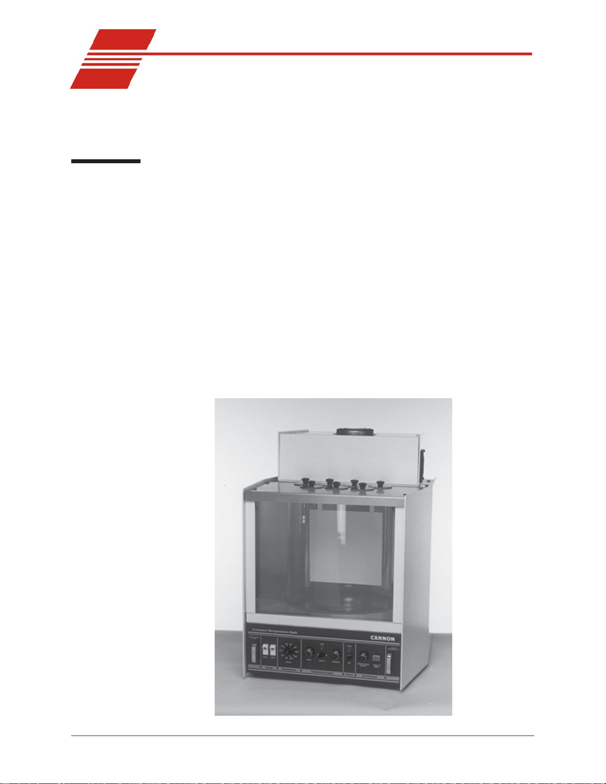
The CANNON
maintain precise temperatures at a wide range of settings for accurate
viscosity measurements. Because of its temperature stability and ease of
use, it is also suitable for any other application where temperatures must
be maintained within close tolerances.
The CANNON® CT-1000HT will maintain temperatures of 25°C to
100°C within 0.01°C, and temperatures of 101°C to 200°C within
0.03°C. The temperature stability of the CT-1000HT meets the accuracy
requirements of ASTM D 445 for kinematic viscosity measurements.
A built-in cooling coil, when connected to tap water or a cooling system,
permits operation below or slightly above ambient temperature. (T emperature stability at or below ambient may vary depending on the quality
of the external cooling unit.)
®
CT-1000HT Constant Temperature Bath is designed to
Figure 1: The CT-1000
CANNON
Revision 1.1b—June, 2011; CANNON
2139 High Tech Road • State College, PA 16803 • USA
®
CT-1000HT Constant Temperature Bath
®
Instrument Company
Page 4

2
Manual
NOTE
Temperature selection
Bath description
This manual is intended to provide information on the installation,
®
characteristics and operation of the CANNON
CT-1000HT Constant
T emperature Bath.
The CT-1000 video does not contain information regarding temperature
selection options above 150°C.
T en of the most commonly-used temperatures for kinematic viscosity
measurement can be set by using a switch on the bath front panel. The
bath will equilibrate within a fraction of one degree of the desired
temperature. A fine-tuning control permits further temperature adjustments. By using the variable temperature adjustment procedure, nearly
any temperature within the operating range of the instrument may be
obtained.
The bath chamber is a cylindrical clear vessel 300 mm (12 inches) in
diameter and 300 mm (12 inches) high. A stainless steel baffle is located
in the center of the bath and provides a convenient backdrop for viewing
viscometers placed in the bath. The top cover contains seven round holes
51 mm (two inches) in diameter for insertion of viscometer holders. Two
additional holes are provided for thermometers. T win fluorescent lamps
provide glare-free illumination of the bath.
Safety features
Overheat thermistor
Thermistor detection/cutoff
Liquid-level control float
A solid-state control circuit equipped with a stainless steel-encased
thermistor provides proportional temperature control. A motor-driven
stirrer ensures that a uniform temperature is maintained throughout the
bath.
The bath housing is fabricated from heavy aluminum and coated with a
corrosion-resistant epoxy . The top cover consists of three layers; a
stainless steel top surface, an insulating layer, and a bottom stainless steel
heat reflector.
A thermistor in the bath senses any over -temperature fault condition. If
such a condition occurs, all power is removed from the bath until an
operator resets the over-temperature limit circuit.
If the control thermistor is disconnected, all power to the bath heaters is
cut off.
Operation of the bath is not possible unless it is filled with liquid to a safe
operating level. A liquid-level control float prevents the control circuit
from heating the bath until the safe operating level is attained. The bath
heaters are automatically turned off if the bath liquid drops below the
minimum safe level.
CANNON
Revision 1.1b—June, 2011; CANNON
2139 High Tech Road • State College, PA 16803 • USA
®
CT-1000HT Constant Temperature Bath
®
Instrument Company
Page 5

Operator safety
Please observe the following safety procedures and notices for proper
operation of your CT-1000HT bath. Deviation from the installation,
operation or maintenance procedures described in this manual may result
in a hazardous situation and may void the manufacturer's warranty .
• Make sure that your unit is operated only by qualified personnel
• Make sure that you read and understand all operating instructions
and safety precautions listed in this manual before installing or
operating your unit. If you have questions regarding instrument
operation or documentation, contact CANNON
®
Instrument Com-
pany.
• Transport the unit with care. Sudden jolts or drops may cause damage to components.
• Observe all warning labels.
• Never remove warning labels.
• Never operate damaged or leaking equipment.
• Never operate the equipment with damaged mains power cables.
• The instrument power cord should only be connected to a suitable
AC mains power source (with protective earth ground) matching the
specifications of the S/N label.
• Position power cords so that they are not likely to be walked on or
pinched by items placed on or against them. Keep all connections as
neat as possible.
• To disconnect the power cord, pull it out by the plug. Never pull the
cord itself.
• Never operate the unit without appropriate levels of approved bath
fluid in the bath.
• Do not add bath fluid to the bath unless the bath temperature is
within 10°C of ambient.
• Do not splash liquids on the external surfaces of the bath, including
the Pyrex® bath jar.
• Do not obstruct the cooling vent on the top of the bath.
• Always turn off the unit and disconnect the mains cable from the
power source before performing approved service or maintenance
procedures, or before moving the unit.
• Always empty the bath before moving the unit.
• Refer all service and repairs to qualified personnel.
• Do not attempt to service the unit beyond the service and/or repair
procedures detailed in this manual. Contact CANNON® Instrument
Company for all additional service/repair needs.
3
General Caution
In addition to the warnings listed above, additional cautions are posted
throughout the manual. These warnings may be designated by an appropriate symbol inside an equilateral triangle. General cautions are indicated with an exclamation point (see diagram, left). Read and follow
these important instructions. Failure to observe these instructions can
result in permanent damage to the unit, significant property damage, and
personal injury.
CANNON
Revision 1.1b—June, 2011; CANNON
2139 High Tech Road • State College, PA 16803 • USA
®
CT-1000HT Constant Temperature Bath
®
Instrument Company
Page 6
4
Hot surface cautions (see diagram, left) may be attached on or near hot
surfaces of the instrument. Avoid touching these surfaces during instrument operation above 50°C.
Hot Surface Caution
The Protective Conductor Terminal symbol is used to indicate required
ground connections for your instrument electrical supply .
Protective Conductor
WARNING
MAINS
AC Power Input Symbol
( O )
Supply OFF Symbol
Specifications
When supplying power to this instrument, connect the protective ground
(earth) terminals of the instrument to the protective conductor of the
(supplied) line (MAINS) power cord. The main plug for the power cord
should only be inserted in a socket outlet (receptacle) provided with a
protective ground (earth) contact.
Do not use an extension cord (power
cable) without a protective conductor (grounding).
The ~MAINS symbol indicates instructions or connections for the AC
power supply . The AC Power input must match the electrical specifications listed on the label on the rear panel of the instrument. The supplied
AC Mains power cord must be attached to the connector labelled
~MAINS. This connection serves as a means of disconnect and should be
readily accessible.
The (O) symbol indicates the OFF position for the electrical switches for
your unit (AC Mains or accessories).
SNOITACIFICEPSTH0001-TC
snoisnemiD )ni52x02x52.71(hgihmm536xpeedmm805xediwmm834
thgieW diulfhtabtuohtiw)sbl801(gk94
erutarepmeT
yticapaChtaB )lag5.4(L71
gnitarepO
snoitidnoC
esuF
tnemecalpeR
lacirtcelE *]leballenapraertnemurtsninostnemeriuqerotegatlovenilhctaM[
ecnailpmoC )CEE/32/37(evitceridegatlovwoL;)CEE/633/98(evitceridCME
thgieWgnippihS rajhtab.lcni)sbl031(gk95
noisicerP/egnaR
rebmuNgolataC
C°10.0±C°001otC°52
C°30.0±C°002otC°101
IIyrogetacnoitallatsnI;gnisnednoc-nonHR%09-%01,C°03-C°51
2eergednoitulloP
"¼x"¼-1;A51V052M
).ces06,CDV0091(TOP-IH
--72A-6279
--92A-6279
tinuehthtiwdedivorpdrocrewopdevorppaehtylnoesU*
sttaw0051,zH06/05;%01±CAV511
sttaw0051,zH06/05;%01±CAV032
CANNON
Revision 1.1b—June, 2011; CANNON
2139 High Tech Road • State College, PA 16803 • USA
®
CT-1000HT Constant Temperature Bath
®
Instrument Company
Page 7
CHAPTER
5
2
CAUTION
UNPACKING AND ASSEMBLY
This chapter of the manual provides assistance in unpacking and assembling the CT-1000HT Constant T emperature Bath. For additional assistance, consult the instructional video.
CT-1000HT components are heavy. Obtain necessary assistance before
moving heavier packed and unpacked items.
Unpacking the CT-1000HT
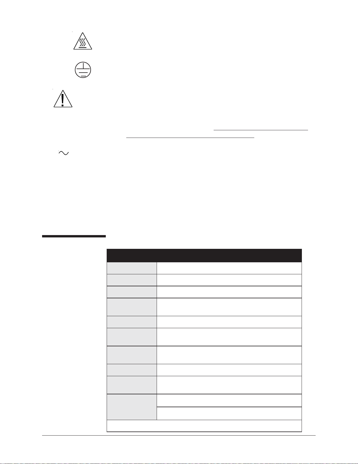
The CANNON® CT-1000HT Constant Temperature Bath is shipped in
two boxes:
Box 1 contains the glass jar, front glass panel pieces, jar gasket top,
trimpot adjust screwdriver, Allen wrench, seven hole covers, rubber
thermometer holder and instruction manual.
Box 2 contains the bath housing, including the electronics drawer.
Box 2 also contains a smaller box with the motor and stirrer, including the impellers (2) and mounting plate.
The bath unit housing is shipped completely assembled. However, the
glass jar, the glass panels, and the motor and stirrer must be installed in it.
T o allow this, some disassembly of the bath unit housing is required. The
tools required are a utility knife, Phillips screwdriver, and a 1/8" Allen
wrench. The Allen wrench is included with the bath.
Figure 2: Primary bath components after unpacking
CANNON
Revision 1.1b—June, 2011; CANNON
2139 High Tech Road • State College, PA 16803 • USA
®
CT-1000HT Constant Temperature Bath
®
Instrument Company
Page 8
6
Assembly procedure
1. Unpack the bath unit housing.
2. Move the bath unit housing to its
permanent location on the
laboratory bench.
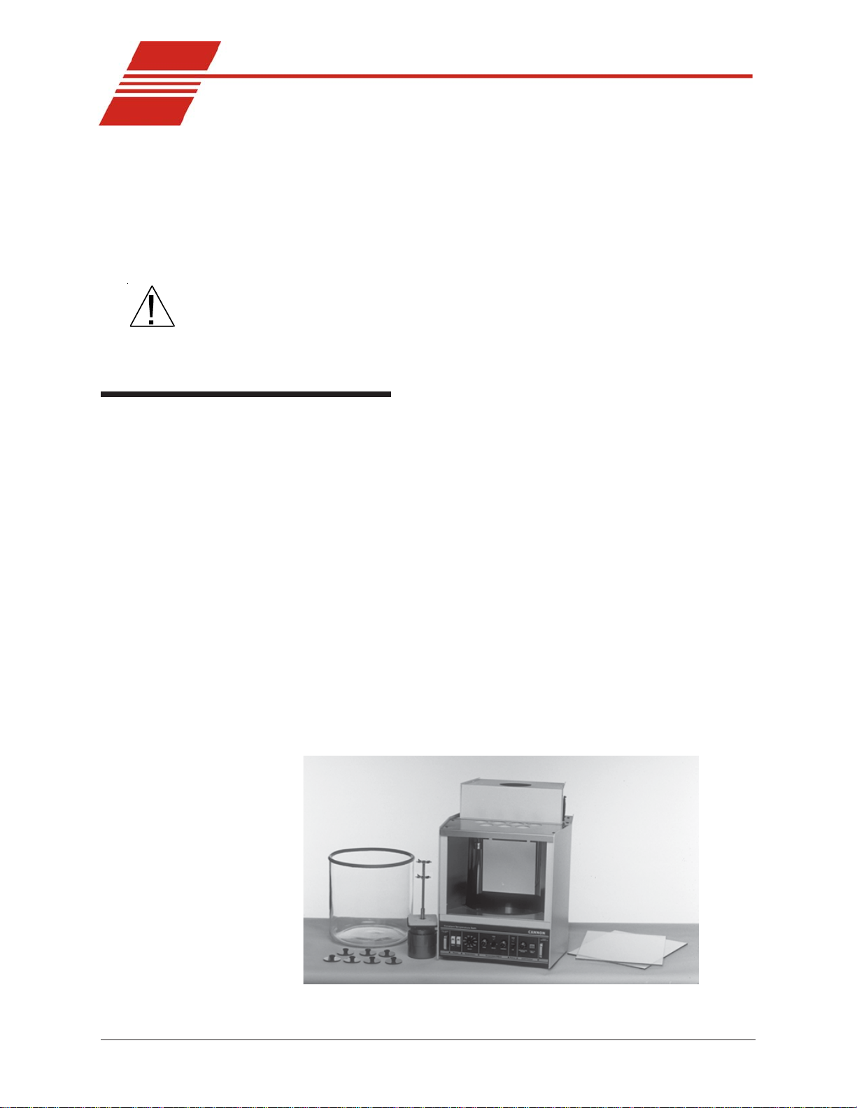
3. Remove all eight screws from the
stainless steel top covers (see
Figure 3).
4. Disconnect all probes, heaters,
and float switch from the rear
panel.
Figure 3: Removing screws
from top cover
5. Remove the front top cover and rear top cover (see Figure 4 and 5).
Use caution when removing the rear top cover because the temperature control probes and heating elements are attached to it.
Figure 4:
Removing front cover
Figure 5:
Removing rear cover
Glass jar installation
1. Remove the glass jar from its
CAUTION
The glass jar is heavy. Use caution
when lifting it.
2. Make sure the Viton® support
3. Place the Viton
CANNON
Revision 1.1b—June, 2011; CANNON
2139 High Tech Road • State College, PA 16803 • USA
box.
ring is seated properly around
the bottom jar opening in the
bath unit (see Figure 6).
®
rubber gasket around the top rim of the jar (see
Figure 6: Checking support ring
Figure 7, next page). The ends of the gasket should meet with no gap
when placed around the rim. If necessary , trim one end of the gasket
to achieve a snug fit.
®
CT-1000HT Constant Temperature Bath
®
Instrument Company
Page 9

4. Remove the large piece of foam
packing from the inside of the
cabinet. Also remove the small
piece of foam from the float level,
located on the upper left-hand
corner of the inside of the cabinet.
5. Lower the glass jar into the cabinet
so it seats evenly on the rubber
support ring (see Figure 8).
7
6. Unwrap the two glass panels. Place
the thinner of the two piece of
glass in the slot closest to the jar
(see Figure 9).
7. Place the wider piece of glass in
the front slot furthest away from
the jar. The middle slot is left
empty for air circulation/cooling.
8. Replace the rear top cover. Align
the four holes, then insert and
tighten the screws.
9. Replace the front top cover.
Line up the four holes, then
insert and tighten the screws.
10. To ensure that the gasket forms
a tight seal with the top covers
of the bath, proceed as follows:
Figure 7: Placing gasket
Figure 8: Installing bath jar
CAUTION
11. Pull out the drawer using the
handles provided, disconnecting the two connection cables
as you do so.
Figure 9: Placing inner glass plate
You will need to pull the AC line (power) cord through the rear panel
opening as you remove the drawer—you should not try to remove the
cord until you loosen the screw securing the power cord to its connection
on the back of the drawer).
12. Press down or pull up on the plastic release bars on either side of the
drawer track to release the drawer, then pull the drawer completely
free of the unit and set it aside.
13. When the drawer is removed, locate the four 1/4-20 set screws
visible at the top of the drawer opening underneath the bath.
14. Turn the set screws clockwise with the Allen wrench (included with
CANNON
Revision 1.1b—June, 2011; CANNON
2139 High Tech Road • State College, PA 16803 • USA
®
CT-1000HT Constant Temperature Bath
®
Instrument Company
Page 10

8
the bath) until the top of the jar forms a tight seal with the covers
(see Figure 10). Make sure you tighten the set screws uniformly so
the jar remains level.
15. Run the AC cord
through the rear panel
opening
16. Replace the drawer in
the slide tracks and push
the drawer back into its
opening. Insert the two
plugs into the rear of the
drawer assembly .
Figure 10: Adjusting set screws
Motor-stirrer
Complete the assembly of the bath, including the motor-stirrer installation, per the instructions below:
1. Take the motor/stirrer from its box. Remove the two screws on the
top heater housing and lift off the housing (see Figure 11).
2. After checking the impeller blades to make sure that the flat sections
all lie in the same plane, insert the motor stirrer in the opening
provided (see Figure 12).
Figure 11: Removing housing Figure 12: Installing motor-stirrer
CAUTION
To keep from accidentally bending the motor shaft, do not hold the motor
assembly by the shaft. Use care when inserting the motor shaft and
impeller to prevent damage to delicate components.
NOTE Two standoffs located on either side of the opening for the motor stirrer
serve as locating pins for the motor support pad. The holes in the pad fit
loosely over their heads. The motor line cord should point toward the
rear of the bath (offset slightly to the right or left). The motor stirrer should
now lie flat on the top of the bath.
3. Reattach the top heater housing, making sure that the heater, motor,
and fan cords pass through the left-hand opening (as viewed from the
rear) and that the control probe, over-temperature probe, and level
CANNON
Revision 1.1b—June, 2011; CANNON
2139 High Tech Road • State College, PA 16803 • USA
®
CT-1000HT Constant Temperature Bath
®
Instrument Company
Page 11

switch cords exit from the right opening (as viewed from the rear).
The back lip on the rear top cover fits into the slot on the top heater
housing. Line up the holes, insert screws, and tighten.
4. Connect all plugs and probes to the correspondingly labeled sockets
at the rear of the CT-1000HT bath unit.
5. Adjust the four feet on the bottom of the bath housing to level the
bath. This should be done before filling the bath with fluid.
Inserting viscometer tubes/thermometers
The top cover of the CT-1000HT contains seven apertures, 51 mm (2") in
diameter, for the insertion of viscometer tube holders. Two additional
holes are provided for insertion of thermometers.
9
Inserting viscometer tubes
If necessary , remove the viscometer tube hole cover(s) from the top of
the bath and carefully place the viscometer tube(s), with the proper
holder attached, into the bath through the aperture(s) in the top cover .
NOTE
Thermometer immersion
After filling the bath with fluid, adjust the height of the viscometer tube(s)
to ensure that the liquid under test and/or any timing marks on the tube
are a minimum of 6 mm (¼") below the top level of the liquid.
Proper thermometer immersion is critical for viscosity measurements.
Even a calibrated thermometer will read incorrectly if is it improperly
immersed in the bath. “T otal immersion” kinematic viscosity thermometers should be used with the bulb and only the mercury column beneath
the surface of the liquid, but with the emergent stem above the surface at
ambient temperatures.
NOTE
Different thermometers have different immersion requirements. Refer to the
information included with the thermometer in use for specific instructions.
Power/probe connections
Bath connections
T o complete electronic connections between CT-1000HT bath components, attach the 9-pin thermistor connector from the bath to the THER-
MISTORS connection on the controller rear panel. Connect the bath
power connector from the bath to the BATH POWER female connection
on the controller rear panel.
Thermistor Controller-bath power MAINS
CANNON
Revision 1.1b—June, 2011; CANNON
2139 High Tech Road • State College, PA 16803 • USA
®
CT-1000HT Constant Temperature Bath
®
Instrument Company
Page 12

10
MAINS power connections
To provide power from your MAINS supply, verify line voltage compatibility by checking the label on the rear panel of the CT-1000HT. Then
MA INS
locate the approved power cord (provided) and plug it into the connector
on the CT-1000HT rear panel.
Verify that the power switch for the CT-1000HT is in the OFF position.
Then plug the other end of the power cord into the MAINS power source.
Attaching the vent hose
The CT-1000HT design includes a rear vent for channeling vapors from
the bath to a user's venting system.
T o complete CT-1000HT assembly, attach the length of vent hose included with the instrument to the rear of the CT-1000HT unit and secure
the connection with a hose clamp.
Vent the other end of the hose to your exhaust system, using procedures
and precautions appropriate for your facility and bath fluid.
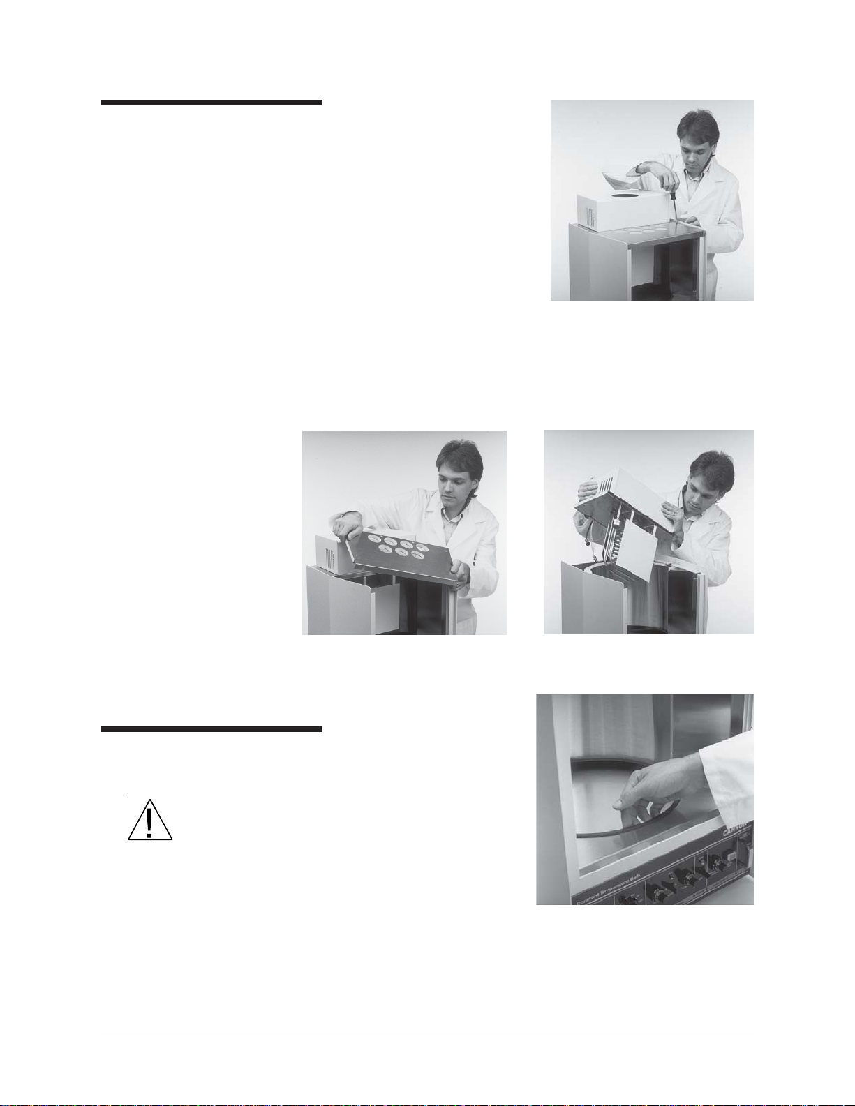
Filling the bath
CAUTION
After CT-1000HT assembly is
complete, you are ready to fill
the bath (see Figure 13).
You should select a bath
liquid appropriate to your
operating temperature range
(see APPENDIX B).
Make sure that the bath is
placed in its intended final
position with the vent hose in
place before adding bath
fluid. The CT-1000HT should
not be moved with bath fluid
in the bath jar. NEVER USE
FLAMMABLE BATH LIQUIDS.
Figure 13: Filling the CT-1000HT bath
1. Make sure that the instrument power is OFF and select a bath liquid
appropriate to your operating temperature range (see APPENDIX B).
2. Fill the jar with bath liquid at ambient temperature to a level sufficient to engage the float switch. This float permits bath operation
when the minimum amount of fluid has been added to the bath jar.
3. Continue to add fluid until the bath liquid level has risen to approximately 40 mm (1.5") of the top of the jar.
CANNON
Revision 1.1b—June, 2011; CANNON
2139 High Tech Road • State College, PA 16803 • USA
®
CT-1000HT Constant Temperature Bath
®
Instrument Company
Page 13

4. Turn the instrument power ON and incrementally heat the bath to
desired control temperature while monitoring the bath liquid level
carefully . The bath level must be 15-20 mm (approximately ½" to
¾") from the top of the jar at the control temperature. If it becomes
apparent that this liquid level will not be achieved, return the bath to
within 10°C of ambient, turn the instrument power OFF and add or
remove liquid as necessary .
5. Repeat step four until you have attained the proper bath liquid level
at the desired control temperature.
11
CAUTION
WARNING
Draining the Bath
Different bath fluids expand at different rates. Do not overfill the bath!
Monitor the level of bath liquid closely when operating the CT-1000HT at
higher temperatures (135-200°C). The bath liquid will expand as the
temperature increases. The CT-1000HT bath jar is not designed to
contain liquid under pressure. If the bath is overfilled, liquid may overflow.
If it becomes necessary to drain the liquid from the bath:
• Obtain a suitable container to hold all of the liquid drained from the
bath (approximately 20-22 liters (4.5 - 5 gallons)).
• Check the bath temperature. The bath liquid should be at or near
ambient temperature.
• Insert a tube into the bath chamber from the top opening and siphon
the liquid from the bath into a container positioned lower than the
bath.
WARNING
Always use a rubber bulb or similar device to apply suction to a tube
containing bath liquids.
CANNON
Revision 1.1b—June, 2011; CANNON
2139 High Tech Road • State College, PA 16803 • USA
®
CT-1000HT Constant Temperature Bath
®
Instrument Company
Page 14

12
This page intentionally left blank.
CANNON
Revision 1.1b—June, 2011; CANNON
®
CT-1000HT Constant Temperature Bath
®
Instrument Company
2139 High Tech Road • State College, PA 16803 • USA
Page 15

CHAPTER
13
3
NOTE
Applying power
CAUTION
BATH OPERATION
The various functions controlling the bath are printed at the bottom of the
front panel of the CT -1000. These functions, reading from lef t to right, are:
1) Power, 2) Temperature, 3) T emperature Adjust, 4) Preheat, and 5)
Limit Control. In this manual the five functions are printed in boldface
upper- and lowercase letters (to match their typeface on the panel). The
switches and dials controlling each function are also printed in boldface
type, but in capital letters (to match their typeface on the panel).
Do not power up the CT -1000HT without completing the installation requirements. Make sure that the mains voltage specified on the rear identification label matches your mains voltage.
NOTE
NOTE
1. Turn the Power BATH switch on.
The bath heaters will not be activated if there is no liquid in the bath.
2. Set the Limit Control TEMPERA TURE ADJUST turn the dial
clockwise to its furthest setting to enable the bath to heat properly .
Proper technique for resetting the dial after the bath reaches operating temperature is described in the following section of the manual.
3. Turn on the Power LIGHT switch to illuminate the interior of the
bath.
4. Move the Temperature Adjust SELECT switch to the left.
5. After releasing its lock, move the Temperatur e Adjust FIXED dial
to 50. Relock the dial.
All the dials except Temperature SELECT are equipped with a dial lock
to prevent accidental changing of dial settings. Push the lock upward to
release the dial. When the dial has been set to the proper position, push
the lock downward to relock the dial.
CANNON
Revision 1.1b—June, 2011; CANNON
2139 High Tech Road • State College, PA 16803 • USA
®
CT-1000HT Constant Temperature Bath
®
Instrument Company
Page 16

14
Setting the bath temperature
There are two ways to set the bath temperature, depending on whether or
not the desired temperature is on the Temperature SELECT dial.
Fixed temperature adjustments
To set the bath to a temperature on the Temperature SELECT switch:
1. Choose a temperature using the Temperature SELECT switch.
NOTE
NOTE
The Preheat switch activates an auxiliary heater for the CT-1000HT. You
may turn it ON to heat up the bath more rapidly. You should turn the
Preheat switch OFF when the desired temperature is reached if the
operational temperature is under 120°C. For bath temperatures in
excess of 120°C, the Preheat switch must remain ON to maintain
temperature control. After the Preheat switch has been turned ON, the
Preheat HEAT light will glow continuously until the bath temperature is
approximately that selected with the Temperature SELECT switch. Then
the light will begin to blink.
The light above the T emperature Adjust control will glow steadily when
the bath is heating. The light will start to blink when the bath temperature
is approximately that selected with the Temperature SELECT switch.
2. To adjust the bath to the exact temperature, read from the kinematic
viscosity thermometer (see Appendix D), then release the dial lock on
the T emperature Adjust FIXED dial and turn the dial to incrementally adjust the temperature. To decrease the temperature, turn the
dial counterclockwise; to increase the temperature, turn the dial
clockwise. Relock the T emperature Adjust FIXED dial after each
adjustment and allow several minutes for the bath to equilibrate.
If the desired temperature cannot be obtained by turning the Temperature Adjust FIXED dial, the small trimpots on the circuit board in the
electronics drawer may require adjustment. Consult CANNON® service.
Variable temperature adjustments
T o set the bath to a temperature that is not on the Temperature SELECT
switch you should use the following procedure:
1. Turn the T emperatur e SELECT switch to the temperature closest to
that desired.
2. Move the Temperature Adjust SELECT switch to the right.
NOTE
The Preheat switch activates an auxiliary heater for the CT-1000HT. You
may turn it ON to heat up the bath more rapidly. You should turn the
Preheat switch OFF when the desired temperature is reached if the
operational temperature is under 120°C. For bath temperatures in
excess of 120°C, the Preheat switch must remain ON to maintain
temperature control. After the Preheat switch has been turned ON, the
CANNON
Revision 1.1b—June, 2011; CANNON
2139 High Tech Road • State College, PA 16803 • USA
®
CT-1000HT Constant Temperature Bath
®
Instrument Company
Page 17

Preheat HEA T light will glow continuously until the bath temperature is
approximately that selected with the Temperature SELECT switch. Then
the light will begin to blink.
The light above the T emperature Adjust control will start to blink when
the bath temperature has approximated the setting on the Temperature
SELECT switch.
3. To adjust the bath to the exact temperature, read from the kinematic
viscosity thermometer (see Appendix D), then release the dial lock on
the T emperatur e Adjust V ARIABLE dial and turn it. To incrementally decrease the temperature, turn the dial counterclockwise; to
increase the temperature, turn the dial clockwise. Relock the Tem-
perature Adjust V ARIABLE dial after each adjustment and allow
several minutes for the bath to equilibrate.
15
NOTE
If a desired bath temperature is within two or three degrees of one on the
Temperature SELECT dial, it is sometimes possible to attain the temperature by using the Temperature Adjust FIXED dial. Because this dial
has a finer adjustment than the Temperature Adjust VARIABLE dial,
the final temperature may be reached more quickly. If you wish to try this
alternate method, follow the procedure for fixed temperature adjustments
given on the previous page.
Attaining lower temperatures
T o attain temperatures below ambient temperature (20-25°C), a coolant
must be pumped through the bath’s cooling coil. The coil is accessed
through the rear of the bath. Coolant temperature should be approximately 3°C below the desired bath temperature. Temperature stability
below ambient temperature may be limited by the flow rate of the coolant.
Adjusting the High Temperature Limit Control
The Limit Control is designed to prevent the bath from overheating if a
malfunction occurs. You should set the Limit Control only after the CT1000HT bath has reached the desired temperature.
NOTE
During this procedure, the temperature of the bath may change slightly ,
but will quickly recover.
1. Using a screwdriver, slowly turn the LC - TEMPERATURE
ADJUST control counterclockwise until the OVER TEMP message
lights up on the LC - PUSH TO RESET button.
2. Turn the control clockwise approximately ¼ to ½ turn.
CANNON
Revision 1.1b—June, 2011; CANNON
2139 High Tech Road • State College, PA 16803 • USA
®
CT-1000HT Constant Temperature Bath
®
Instrument Company
Page 18

16
3. Push the LC - PUSH TO RESET button. If the bath doesn't
recover, repeat step 2 and try again.
CANNON
Revision 1.1b—June, 2011; CANNON
®
CT-1000HT Constant Temperature Bath
®
Instrument Company
2139 High Tech Road • State College, PA 16803 • USA
Page 19

CHAPTER
17
4
Products limited warranty
In addition to other manufacturers’ warrantees, CANNON® Instrument
Company (“the Company”) warrants all products (other than reagents
and chemicals) delivered to and retained by their original purchasers to
be free from defect in material and workmanship for one year from the
date of the Company’s invoice to the purchaser. For a period of one year
from the date of such invoice, the Company will correct, either by repair
or replacement at the Company’s sole election, any defect in material or
workmanship (not including defects due to misuse, abuse, abnormal
conditions or operation, accident or acts of God, or to service or modification of the product without prior authorization of the Company)
without charge for parts and labor. The determination of whether any
product has been subject to misuse or abuse will be made solely by the
Company.
WARRANTY/RETURN
INFORMATION
The Company shall not be liable for any special, incidental, or consequential damages, or any damage to plant, personnel, equipment or
products, directly or indirectly resulting from the use or misuse of any
product. Representations and warranties made by any person, including
dealers and representatives of the Company , which are inconsistent, in
conflict with, or in excess of the terms of this warranty shall not be
binding upon the Company unless placed in writing and approved by an
officer of the Company.
Reagent and chemical warranty
CANNON® Instrument Company (“the Company”) warrants all reagents
and chemicals sold by the Company and delivered to and retained by
their original purchasers to conform to the weight, specifications and
standards stated on the package. The Company will, at its sole option,
either replace or refund the price (net of freight, handling charges and
taxes), of any reagent or chemical sold by the Company which does not
conform to such weight, specifications and standards upon the prompt
return of the unused portion. Except for replacement or refund of the net
price, the Company shall not be liable for any damages occurring as a
consequence of the failure of any reagent or chemical sold by the Company to conform to the weight, specifications and standards stated on the
package.
CANNON
Revision 1.1b—June, 2011; CANNON
2139 High Tech Road • State College, PA 16803 • USA
®
CT-1000HT Constant Temperature Bath
®
Instrument Company
Page 20

18
Returning a product to CANNON
Procedure
Before returning a CANNON
attempt to identify the problem. If, after careful checking, the problem
remains unidentified or unsolved, telephone CANNON® Instrument
Company (or the local service agent) to consult with a product specialist.
If the specialist cannot recommend a simple solution or repair, CAN-
NON® will authorize the return of the product through the issuance of a
Receiving Authorization number (RA).
CANNON® Telephone Number 814-353-8000
CANNON® Fax Number 814-353-8007
Products returned to CANNON
to the following address:
CANNON Instrument Company
A TTN: Return Authorization # __________
2139 High Tech Road
State College, P A 16803 USA
Please include the following:
®
®
product for repair or service, make every
®
must be carefully packed. Ship prepaid
Required information
Hazardous materials
Shipping notification
• The Receiving Authorization number (RA).
• The name and telephone number of the person at your company to
contact regarding the product.
• Shipping and billing instructions for the return of the product to your
location.
• A detailed explanation of the reason for the return.
If the product is not covered by warranty, the customer will be provided
with an estimate of the repair costs and asked for approval before any
repairs are made. The customer will be required to issue a purchase
order for the cost of the repairs.
Stringent government regulations restrict the shipment of mercury. Please
contact CANNON
®
before returning a product that could possibly
contain mercury.
Products returned without prior notification (by either telephone or fax),
or without Cannon’s authorization, will not be accepted.
The customer may be billed a testing fee if a product is returned to
CANNON® and found to be working properly.
CANNON
Revision 1.1b—June, 2011; CANNON
2139 High Tech Road • State College, PA 16803 • USA
®
CT-1000HT Constant Temperature Bath
®
Instrument Company
Page 21

CHAPTER
19
A
Problem
Bath does not appear to
have power.
Bath illumination not
functioning.
APPENDIX A — CT-1000HT
PROBLEM ANALYSIS
Probable Cause/Solution
• Power cable not connected to outlet or rear of electrical drawer.
Reconnect cable.
• Over-temperature control set too low. Reset per manual instructions.
• Power out on mains. Restore mains power.
• Separate switch for LIGHT must be on.
• fluorescent lamps may be defective. Replace.
• Lamps may be out of sockets. Tighten lamps.
• Lamp ballast may be defective.
• Power supply to ballast may not be working properly. Replace faulty
compontents.
Bath liquid not agitated.
Bath does not heat.
Bath control outside of
specific limits.
Bath top surface
temperature too high.
• Check connection of stirring motor on rear panel.
• Check for working motor by connecting to outlet with the proper
voltage (see motor label for correct voltage).
• Check connections for sensors on rear panel.
• Check temperature setting — it must be above existing bath
temperature for heat to go on. Adjust if necessary.
• Bath fluid level may be too low. Add fluid per manual instructions.
• Limit Control Temperature Adjust dial may be set too low. Turn the
dial completely clockwise to 999, then press PUSH TO RESET
button. If bath starts, reset the dial per manual instructions.
• Bath fluid viscosity may be too high (if the fluid is too viscous at the
desired temperature the stirring will be inadequate, resulting in
poor control). Select a more appropriate bath fluid.
• Check for normal function of stirring motor and motor impeller. Adjust
and/or replace components if necessary.
• Remove control thermistor probe plug and check resistance with an
ohmmeter (call
temperature).
• Check cooling fan on rear panel.
• Check cooling fan in top assembly.
CANNON
®
for proper resistance at bath
Air bubbles in bath fluid.
• Level of fluid may be too low. Add fluid per manual instructions.
• Stirring impeller may be on shaft with the wrong orientation. Adjust.
• Bath fluid may be too viscous for operation at this temperature.
Select a more appropriate bath fluid.
CANNON
Revision 1.1a—June, 2007; CANNON
2139 High Tech Road • State College, PA 16803 • USA
®
CT-1000HT Constant Temperature Bath
®
Instrument Company
Page 22

24
This page intentionally left blank.
CANNON
Revision 1.1a—June, 2007; CANNON
®
CT-1000HT Constant Temperature Bath
®
Instrument Company
2139 High Tech Road • State College, PA 16803 • USA
Page 23

CHAPTER
21
B
APPENDIX B — CHOOSING A
TEMPERATURE BATH LIQUID
The ideal bath liquid would possess low viscosity , high heat capacity, and
low vapor pressure over a wide range of temperatures. In addition, the
liquid should have a very high flash point and be relatively low in cost. If
the fluid is to be used in a kinematic viscosity bath where it is necessary
to view the instruments through the bath liquid, then it is important for
the liquid to be clear and without color. Unfortunately, no single fluid
meets all these requirements. When selecting a fluid, keep the following
guidelines in mind.
DIUQILHTABLAEDIEHT
ytisocsiV
ytisocsiV
nacgnirritsetaredomtahtoswolyrevebdluohs
.htabehtnistneidargerutarepmetetanimileylevitceffe
taeH
yticapaC
ytilitaloV
Because no single fluid can be used at all possible bath temperatures, the
choice of a suitable fluid must begin by establishing the temperature
range over which the bath will be operated. The following is a list of
operating temperature ranges and some liquids suitable for use in these
ranges:
yticapac
.yticapactaehemasehttuobaevahlliw
taehhgihahtiwdiparsselerahtabehtnisegnahcerutarepmeT
sdiulfhtabrofseciohctsom,retawfonoitpecxeehthtiW.
tneuqerferomeriuqerlliwelitalovylevitalersihcihwdiuqilA
ecafrushtabehttanoitaropavedipar,eromrehtruF.tnemhsinelper
.tluciffideromlortnocgnikam,tceffegniloocasecudorp
CANNON
Revision 1.1a—June, 2007; CANNON
2139 High Tech Road • State College, PA 16803 • USA
®
CT-1000HT Constant Temperature Bath
®
Instrument Company
Page 24

22
)C°002+otC°52(SNOITPODIULFHTAB
Silicone fluids
erutarepmeT
sdiuqiLhtaBelbatiuS
)C°(egnaR
C°06+otC°5+ senociliS,sliOytisocsiVwoL,retaW
)tSc1,diulf002woD(
C°001+otC°06+ senocili
S,rotibihnInoitadixOhtiwsliOetihW
)tSc01,diulf002woD(
C°531+otC°001+ )tSc02,diulf002woD(senociliS
C°002+otC°531+ )tSc05,diulf002woD(senociliS
Silicone fluids are available in a wide range of viscosities and can be
used over a wide range of temperatures if the proper selection of viscosity is made for the temperature range of interest. Silicones are also
relatively expensive liquids. However, a bath containing silicones
requires extra care when used for capillary viscometry . If silicones are
introduced into a viscometer capillary , its calibration factor will be
altered by a significant amount.
Water
Refined white oils
Water is almost the ideal fluid in the temperature range in which it can be
used. Because in some cases there is a tendency for algae formation,
some degree of water treatment may be necessary . Water can be used at
temperatures close to the boiling point, but water replenishment to offset
evaporation becomes a nuisance and the hot vapor can make working
above the bath uncomfortable. Also, it may be dif ficult to establish
optimum control at elevated temperatures because of the rapid cooling
resulting from surface evaporation.
Refined white oils (paraffin oils) of relatively low viscosity can be used
at temperatures above the level at which water becomes unsatisfactory .
Because these oils will turn faintly yellow and continue to darken with
prolonged exposure to heat, we recommend adding an oxidation inhibitor
to retard discoloration. The addition of an inhibitor will prolong the
useful life of the oil, but it will eventually become as dark as untreated
oil.
The search for more suitable bath oils is unending. Hydrogenated vegetable oils, coconut oil, synthetic oils, and certain chemical compounds
have been used with some success at various temperatures.
CANNON
Revision 1.1a—June, 2007; CANNON
2139 High Tech Road • State College, PA 16803 • USA
®
CT-1000HT Constant Temperature Bath
®
Instrument Company
Page 25

Page 26

24
This page intentionally left blank.
CANNON
Revision 1.1a—June, 2007; CANNON
®
CT-1000HT Constant Temperature Bath
®
Instrument Company
2139 High Tech Road • State College, PA 16803 • USA
 Loading...