

Page 1

CONTENTS
i
1
2
3
INTRODUCTION 1
Overview ............................................................................................................................. 1
Safety features ...................................................................................................................... 3
Operator Safety .................................................................................................................. 3
UNPACKING AND ASSEMBLY 5
Unpacking the CT -1000 ....................................................................................................... 5
Assembly procedure ............................................................................................................. 5
Glass jar installation .............................................................................................................. 6
Motor-stirrer ............................................................................................................ 8
Inserting viscometer tubes/thermometers................................................................................ 9
Filling the bath .................................................................................................................... 10
Draining the Bath ................................................................................................................ 11
BATH OPERATION 13
Turning on the CT -1000...................................................................................................... 13
Setting the bath temperature ................................................................................................ 14
Fixed temperature adjustments ................................................................................ 14
V ariable temperature adjustments ............................................................................ 14
Setting the Limit Control ..................................................................................................... 15
A
B
C
D
APPENDIX A — CT-1000 PROBLEM ANALYSIS 17
APPENDIX B — CORRECTING SHAFT & IMPELLER MISALIGNMENT 19
Shaft run-out correction ...................................................................................................... 19
APPENDIX C — CHOOSING A TEMPERATURE BATH LIQUID 21
APPENDIX D — ADJUSTING TRIMPOTS (POTENTIOMETERS) 23
CANNON
®
CT-1000 Constant Temperature Bath Instruction & Operation Manual
Revision 3.1e—June, 2011; CANNON® Instrument Company
2139 High Tech Road • State College, PA • USA 16803
Page 2

ii
E
F
APPENDIX E — CT-1000 SPARE PARTS LIST 25
WARRANTY/RETURN INFORMATION 27
Products limited warranty.................................................................................................... 27
Reagent and chemical warranty ........................................................................................... 27
Returning a product to CANNON®.................................................................................... 28
CANNON
®
CT-1000 Constant Temperature Bath Instruction & Operation Manual
Revision 3.1e—June, 2011; CANNON® Instrument Company
2139 High Tech Road • State College, PA • USA 16803
Page 3
1
1
Overview
CT-1000 function
Temperature range
Manual/video
INTRODUCTION
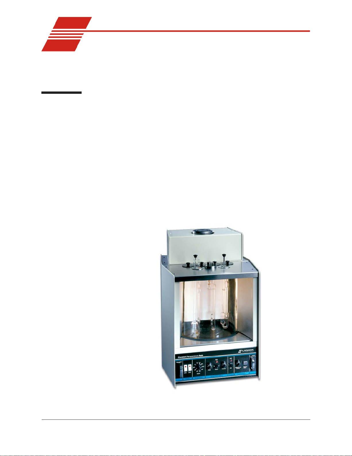
The CANNON® CT-1000 Constant Temperature Bath is designed to
maintain precise temperatures at a wide range of settings for accurate
viscosity measurements. Because of its temperature stability and ease of
use, it is also suitable for any other application where temperatures must
be maintained within close tolerances.
The CANNON® CT-1000 will maintain temperatures of 20°C to 100°C
within 0.01°C and temperatures of 101°C to 150°C within 0.03°C.
This manual is intended to provide information on the installation,
characteristics and operation of the CANNON® CT-1000 Constant
T emperature Bath. The manual materials are supplemented and enhanced
CANNON
Figure 1: The CT-1000
®
CT-1000 Constant Temperature Bath Instruction & Operation Manual
Revision 3.1e—June, 2011; CANNON® Instrument Company
2139 High Tech Road • State College, PA • USA 16803
Page 4

2
by an instructional video shipped with the bath.
Temperature selection
Bath description
T en of the most commonly-used temperatures for kinematic viscosity
measurement can be set by using a switch on the bath front panel. The
bath will equilibrate within a fraction of one degree of the desired
temperature. A fine-tuning control permits further temperature adjustments. By switching to the variable setting on the front panel, the operator can set any temperature within the operating range of the instrument.
The bath chamber is a cylindrical clear Pyrex® vessel 300 mm (12 inches)
in diameter and 300 mm (12 inches) high. A stainless steel baf fle is
located in the center of the bath and provides a convenient backdrop for
viewing viscometers placed in the bath. The top cover contains seven
round holes 51 mm (two inches) in diameter for insertion of viscometer
holders. T wo additional holes are provided for thermometers. Twin
fluorescent lamps provide glare-free illumination of the bath.
A solid-state control circuit equipped with a stainless steel-encased
thermistor provides proportional temperature control. A motor-driven
stirrer ensures that a uniform temperature is maintained throughout the
bath.
The bath housing is fabricated from heavy aluminum and coated with a
corrosion-resistant epoxy . The top cover consists of three layers; a
stainless steel top surface, an insulating layer, and a bottom stainless steel
heat reflector.
Temperature stability
The temperature control of ± 0.01°C below 100°C, and ± 0.03°C from
100 to 150°C, provides the sensitivity required by ASTM D 445 for
kinematic viscosity measurements. A built-in cooling coil, when connected to tap water or a cooling system, permits operation below or
slightly above ambient temperature.
snoitacificepS0001-TC
snoisnemiD
)sehcni32x52.81x52.71(
hgihmm485xpeedmm464xediwmm834
yticapaC )lag5.4(L71
thgieW )bl59(gk34
thgieWgnippihS )bl321(gk8.55
sttaw0041,zH06/05,CA)ledomtlov-021(02A-6279
rebmuNgolataC
sttaw0041,zH06/05,CA)ledomtlov-042(52A-6279
CANNON
®
CT-1000 Constant Temperature Bath Instruction & Operation Manual
Revision 3.1e—June, 2011; CANNON® Instrument Company
2139 High Tech Road • State College, PA • USA 16803
Page 5

Safety features
3
Overheat thermistor
Thermistor detection/cutoff
Liquid-level control float
Operator Safety
A thermistor in the bath senses any over-temperature fault condition. If
such a condition occurs, all power is removed from the bath until an
operator resets the over-temperature limit circuit.
If the control thermistor is disconnected, all power to the bath heaters is
cut off.
Operation of the bath is not possible unless it is filled with liquid to a safe
operating level. A liquid-level control float prevents the control circuit
from heating the bath until the safe operating level is attained. The bath
heaters are automatically turned off if the bath liquid drops below the
minimum safe level.
All technicians who use the CT-1000 should follow these basic safety
procedures:
Do not place the CT-1000 system on an unstable cart or stand. The
CT-1000 should be placed on a stable laboratory table or bench.
If any liquids are spilled into the electronic components of the CT-
1000, contact CANNON
®
Instrument Company immediately .
Do not position power cords so that they are likely to be walked on
or pinched by items placed on or against them. Keep all connections
as neat as possible.
If the CT-1000 will not be used for an extended period of time,
unplug the power cord from the wall outlet. To disconnect the power
cord, pull it out by the plug. Never pull the cord itself.
CAUTION
Do not attempt to service the CT-1000 system by removing panels and
trying to effect repairs. Contact CANNON® Instrument Company regarding service and repair needs.
CAUTION The bath fluid used with the CT-1000 may be dangerous. Use the proper
safety precautions when handling the bath fluid in use (refer to the
Material Safety Data Sheet included with the bath fluid for more detail.)
CANNON
®
CT-1000 Constant Temperature Bath Instruction & Operation Manual
Revision 3.1e—June, 2011; CANNON® Instrument Company
2139 High Tech Road • State College, PA • USA 16803
Page 6

4
This page intentionally left blank.
CANNON
®
CT-1000 Constant Temperature Bath Instruction & Operation Manual
Revision 3.1e—June, 2011; CANNON® Instrument Company
2139 High Tech Road • State College, PA • USA 16803
Page 7
5
2
UNPACKING AND ASSEMBLY
This chapter of the manual provides assistance in unpacking and assembling the CT-1000 Constant Temperature Bath. For additional assistance,
consult the instructional video.
Unpacking the CT-1000
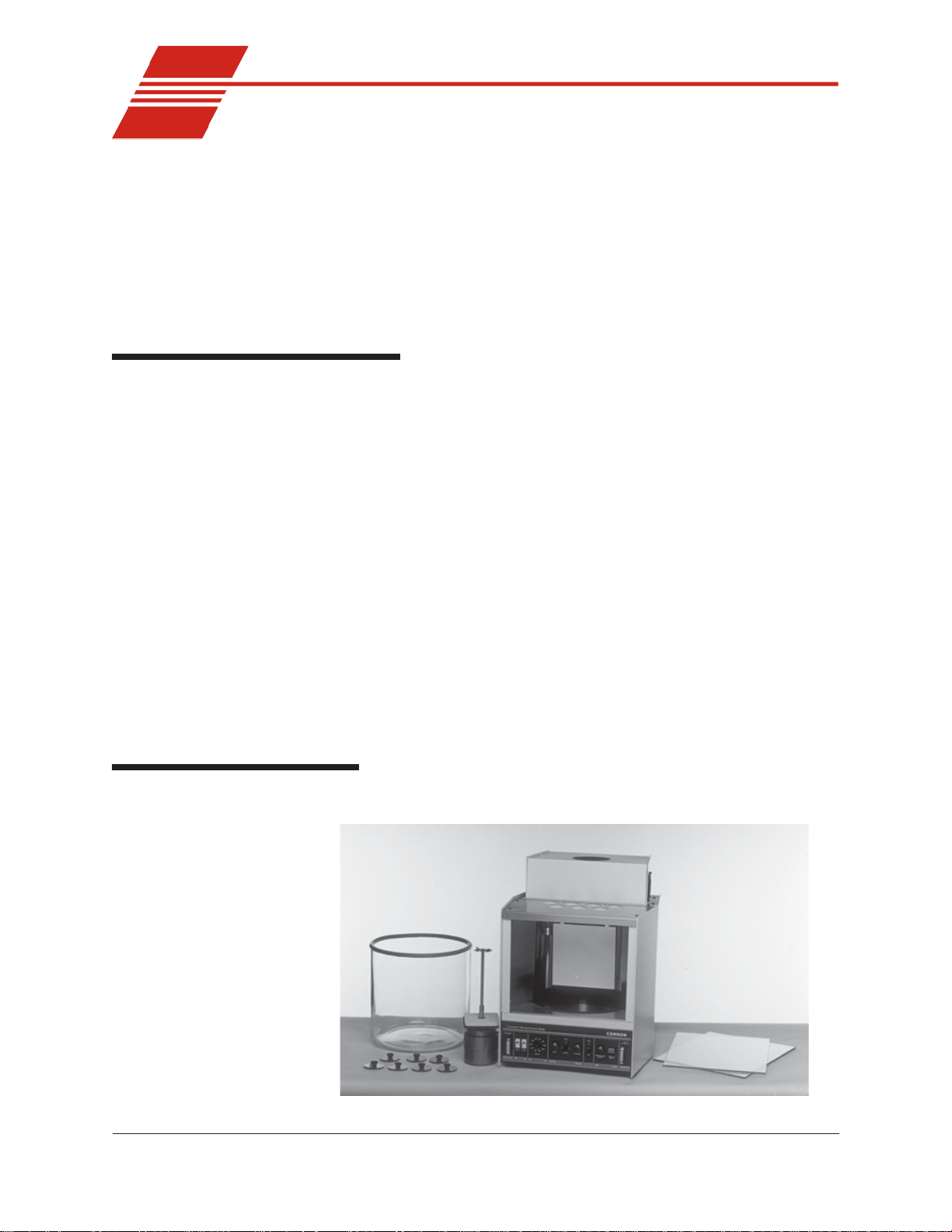
The CANNON® CT-1000 Constant Temperature Bath is shipped in two
boxes:
Box 1 contains the glass jar, front glass panel pieces, jar gasket top,
trimpot adjust screwdriver, Allen wrench, seven hole covers, rubber
thermometer holder and instruction manual.
Box 2 contains the bath housing, including the electronics drawer.
Box 2 also contains a smaller box with the motor and stirrer, including the impeller and mounting plate.
The bath unit housing is shipped completely assembled. However, the
glass jar, the glass panels, and the motor and stirrer must be installed in it.
T o allow this, some disassembly of the bath unit housing is required. The
tools required are a utility knife, phillips screwdriver, and a 1/8" Allen
wrench. The Allen wrench is included with the bath.
Assembly procedure
1. Unpack the bath unit housing.
CANNON
Figure 2: Primary bath components after unpacking
®
CT-1000 Constant Temperature Bath Instruction & Operation Manual
Revision 3.1e—June, 2011; CANNON® Instrument Company
2139 High Tech Road • State College, PA • USA 16803
Page 8
6
2. Move the bath
unit housing to its
permanent location on the
laboratory bench.
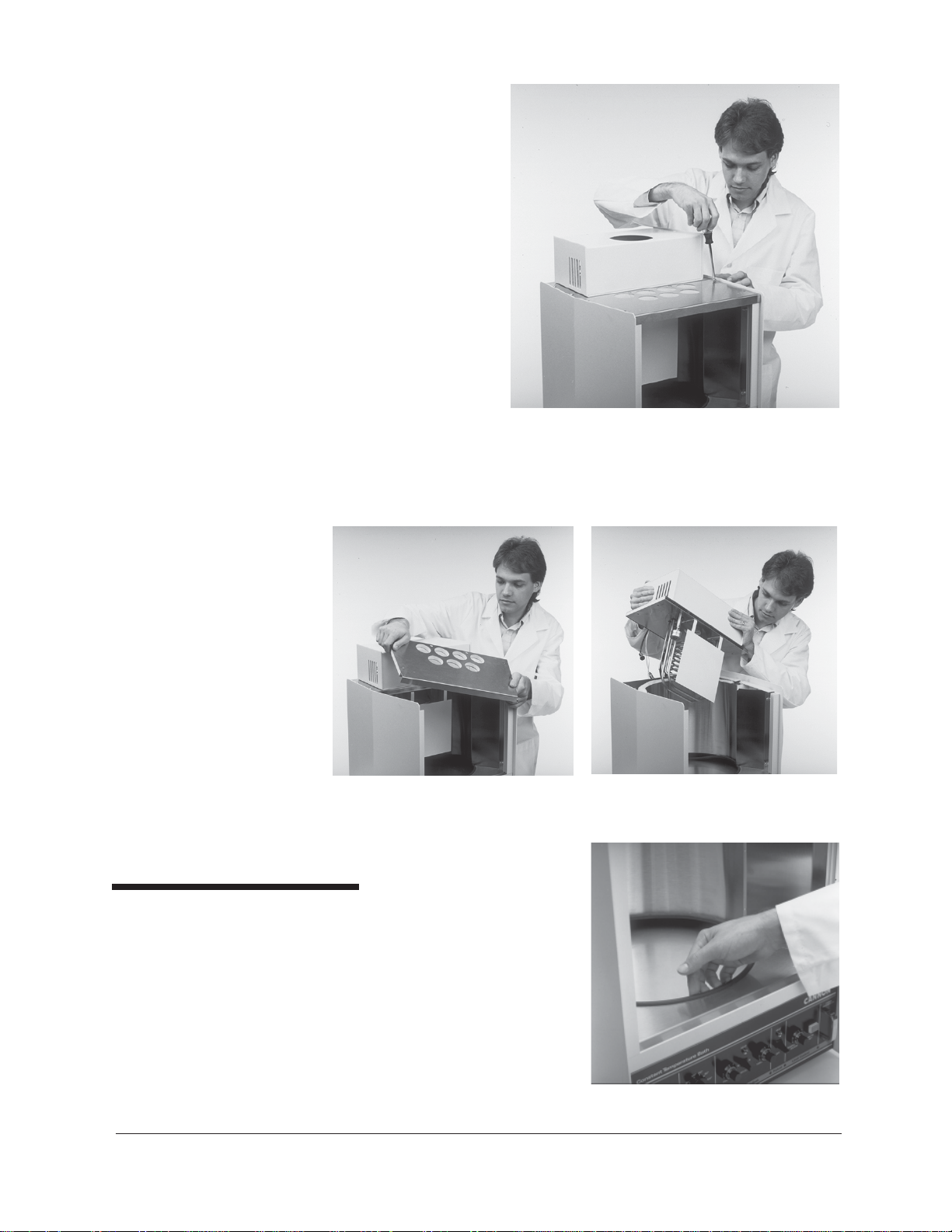
3. Remove all eight
screws from the
stainless steel top
covers (see Figure
3).
4. Disconnect all
probes, heaters,
and float switch
from the rear
panel.
5. Remove the front top cover and rear top cover (see Figure 4 and 5).
Use caution when removing the rear top cover because the temperature control probes and heating elements are attached to it.
Figure 3: Removing screws from top cover
Figure 4:
Removing front top cover
Glass jar installation
1. Remove the glass jar from its
WARNING
CANNON
The glass jar is heavy. Use
caution when lifting it.
2. Make sure the rubber support
®
CT-1000 Constant Temperature Bath Instruction & Operation Manual
Revision 3.1e—June, 2011; CANNON® Instrument Company
2139 High Tech Road • State College, PA • USA 16803
box.
ring is seated properly around
the bottom jar opening in the
bath unit (see Figure 6).
Figure 5:
Removing rear top cover
Figure 6: Checking support ring
Page 9
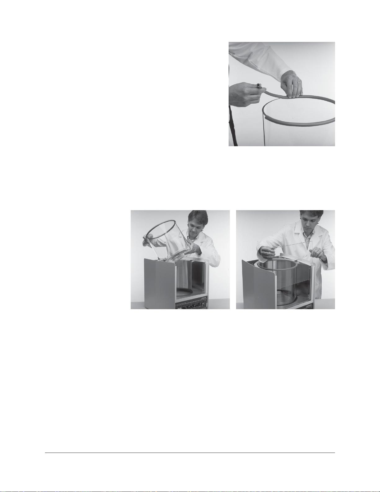
3. Place the rubber gasket
around the top rim of the
jar (see Figure 7). The
rubber may have to be
trimmed slightly to allow
the ends of the rubber
gasket to meet with no gap
when placed around the
rim.
4. Remove the large piece of
foam packing from the
inside of the cabinet. Also
remove the small piece of
foam from the float level,
Figure 7: Placing gasket
located on the upper lefthand corner of the inside of the cabinet.
5. Lower the glass jar into the cabinet so it seats evenly on the rubber
support ring (see Figure 8).
7
CANNON
Figure 8: Installing bath jar Figure 9: Placing inner glass plate
6. Unwrap the two glass panels. Place the thinner of the two piece of
glass in the slot closest to the jar (see Figure 9).
7. Place the wider (tempered) piece of glass in the front slot furthest
away from the jar. The middle slot is left empty as a vapor barrier.
8. Replace the rear top cover. Align the four holes, then insert and
tighten the screws.
9. Replace the front top cover. Line up the four holes, then insert and
tighten the screws.
10. T o ensure that the gasket forms a tight seal with the top covers of the
bath, proceed as follows:
®
CT-1000 Constant Temperature Bath Instruction & Operation Manual
Revision 3.1e—June, 2011; CANNON® Instrument Company
2139 High Tech Road • State College, PA • USA 16803
Page 10

8
11. Pull out the drawer using the handles provided, disconnecting the
two connection cables as you do so.
CAUTION
You will need to pull the AC line (power) cord through the rear panel
opening as you remove the drawer—you should not try to remove the
cord until you loosen the screw securing the power cord to its connection
on the back of the drawer).
12. Press down or pull up on the plastic release bars on either side of the
drawer track to release the drawer, then pull the drawer completely
free of the unit and set it aside.
13. When the drawer is removed, locate the four 1/4-20 set screws
visible at the top of the drawer opening underneath the bath.
14. Turn the set screws
clockwise with the
Allen wrench (included with the bath)
until the top of the jar
forms a tight seal
with the covers (see
Figure 10). Make
sure you tighten the
set screws uniformly
so the jar remains
level.
FIgure 10: Adjusting seal with set screws
Motor-stirrer
NOTE
15. Run the AC cord through the rear panel opening
16. Replace the drawer in the slide tracks and push the drawer back into
its opening. Insert the two plugs into the rear of the drawer assembly .
Complete the assembly of the bath, including the motor-stirrer installation, per the instructions below:
1. T ake the motor/stirrer from its
box. Remove the two screws on
the top heater housing and lift off
the housing (see Figure 11).
2. After checking the impeller blades
to make sure that the flat sections
all lie in the same plane (see
Appendix B), insert the motor
stirrer in the opening provided (see
Figure 12, next page).
To keep from accidentally bending the motor shaft, do not hold the motor
assembly by the shaft. Use care when inserting the motor shaft and
impeller to prevent damage to delicate components.
Figure 11: Removing housing
CANNON
®
CT-1000 Constant Temperature Bath Instruction & Operation Manual
Revision 3.1e—June, 2011; CANNON® Instrument Company
2139 High Tech Road • State College, PA • USA 16803
Page 11

9
NOTE
Two screws located on either side
of the opening for the motor stirrer
serve as locating pins for the
motor support pad. Do not
remove these screws; the holes in
the pad fit loosely over their
heads. The motor line cord should
point toward the rear of the bath
(offset slightly to the right or left).
The motor stirrer should now lie flat
on the top of the bath.
3. Reattach the top heater
Figure 12: Installing the motor
housing , making sure that the heater, motor, and fan cords pass
through the left-hand opening (as viewed from the rear) and that the
control probe, over-temperature probe, and level switch cords exit
from the right opening (as viewed from the rear). The back lip on the
rear top cover fits into the slot on the top heater housing. Line up the
holes, insert screws, and tighten.
4. Connect all plugs and probes to the correspondingly labeled sockets
at the rear of the CT-1000 bath unit.
5. Adjust the four feet on the bottom of the bath housing to level the
bath. This should be done before filling the bath with fluid.
Inserting viscometer tubes/thermometers
The top cover of the CT-1000 contains seven apertures, 51 mm (2”)
in diameter, for the insertion of viscometer tube holders. Two additional
holes are provided for insertion of thermometers.
Inserting viscometer tubes
NOTE
Thermometer immersion
If necessary , remove the viscometer tube hole cover(s) from the top of
the bath and carefully place the viscometer tube(s), with the proper
holder attached, into the bath through the aperture(s) in the top cover .
After filling the bath with fluid, adjust the height of the viscometer tube(s)
to ensure that the liquid under test and/or any timing marks on the tube
are a minimum of 6 mm (¼") below the top level of the liquid.
Proper thermometer immersion is critical for viscosity measurements.
Even a calibrated thermometer will read incorrectly if is it improperly
immersed in the bath. “T otal immersion” kinematic viscosity thermometers should be used with the bulb and only the mercury column beneath
the surface of the liquid, but with the emergent stem above the surface at
ambient temperatures.
NOTE
CANNON
Different thermometers have different immersion requirements. Refer to
the information included with the thermometer in use for specific instructions.
®
CT-1000 Constant Temperature Bath Instruction & Operation Manual
Revision 3.1e—June, 2011; CANNON® Instrument Company
2139 High Tech Road • State College, PA • USA 16803
Page 12

10
Filling the bath
After CT-1000 assembly
is complete, you are
ready to fill the bath.
CAUTION
Make sure that the bath
is placed in its intended
final position before
adding bath fluid. The
CT-1000 should not be
moved with bath fluid in
the bath jar. NEVER USE
FLAMMABLE BATH
LIQUIDS.
1. Make sure that the
instrument power is
OFF and select a
bath liquid appropri-
Figure 13: Filling the CT-1000 bath
ate to your operating
temperature range (see APPENDIX C).
2. Fill the jar with bath liquid at ambient temperature to a level sufficient to engage the float switch. This float permits bath operation
when the minimum amount of fluid has been added to the bath jar.
3. Continue to add fluid until the bath liquid level has risen to approximately 40 mm (1.5") of the top of the jar.
4. Turn the instrument power ON and incrementally heat the bath to
desired control temperature while monitoring the bath liquid level
carefully . The bath level must be 15-20 mm (approximately ½" to
¾") from the top of the jar at the control temperature. If it becomes
apparent that this liquid level will not be achieved, return the bath to
within 10°C of ambient, turn the instrument power OFF and add or
remove liquid as necessary .
5. Repeat step four until you have attained the proper bath liquid level
at the desired control temperature.
CAUTION
Different bath fluids expand at different rates. Do not overfill the bath!
WARNING Monitor the level of bath liquid closely when operating the CT-1000 at
higher temperatures (100-150°C). The bath liquid will expand as the
temperature increases. The CT-1000 bath jar is not designed to contain
liquid under pressure. If the bath is overfilled, liquid may overflow.
CANNON
®
CT-1000 Constant Temperature Bath Instruction & Operation Manual
Revision 3.1e—June, 2011; CANNON® Instrument Company
2139 High Tech Road • State College, PA • USA 16803
Page 13

Draining the Bath
11
If it becomes necessary to drain the liquid from the bath:
Obtain a suitable container to hold all of the liquid drained from the bath
(approximately 20-22 liters or 4.5 - 5 gallons). Make sure that the bath
liquid is within 10°C of ambient temperature. Then insert a tube into the
bath chamber from the top opening and siphon the liquid from the bath
into a container positioned lower than the bath.
WARNING
Always use a rubber bulb or similar device to apply suction to a tube
containing bath liquids.
CANNON
®
CT-1000 Constant Temperature Bath Instruction & Operation Manual
Revision 3.1e—June, 2011; CANNON® Instrument Company
2139 High Tech Road • State College, PA • USA 16803
Page 14

12
This page intentionally left blank.
CANNON
®
CT-1000 Constant Temperature Bath Instruction & Operation Manual
Revision 3.1e—June, 2011; CANNON® Instrument Company
2139 High Tech Road • State College, PA • USA 16803
Page 15

13
3
NOTE
Turning on the CT-1000
The various functions controlling the bath are printed at the bottom of the
front panel of the CT-1000. These functions, reading from left to right,
are: 1) Power, 2) Temperature, 3) Temperature Adjust, 4) Preheat,
and 5) Limit Control. In this manual the five functions are printed in
boldface upper- and lowercase letters (to match their typeface on the
panel). The switches and dials controlling each function are also printed
in boldface type, but in capital letters (to match their typeface on the
panel).
1. Turn the Power BATH switch on.
BATH OPERATION
NOTE
The bath heaters will not be activated if there is no liquid in the bath.
2. Set the Limit Control TEMPERATURE ADJUST turn the dial
clockwise to its furthest setting to enable the bath to heat properly .
Proper technique for resetting the dial after the bath reaches operating temperature is described in the instructional video and in the
following section of the manual
3. Turn on the Power LIGHT switch to illuminate the interior of the
bath.
4. Move the Temperature Adjust SELECT switch to the left.
5. After releasing its lock, move the T emperatur e Adjust FIXED dial
to 50. Relock the dial.
CANNON
®
CT-1000 Constant Temperature Bath Instruction & Operation Manual
Revision 3.1e—June, 2011; CANNON® Instrument Company
2139 High Tech Road • State College, PA • USA 16803
Page 16

14
NOTE
All the dials except Temperature SELECT are equipped with a dial lock
to prevent accidental changing of dial settings. Push the lock upward to
release the dial. When the dial has been set to the proper position, push
the lock downward to relock the dial.
Setting the bath temperature
There are two ways to set the bath temperature, depending on whether or
not the desired temperature is on the Temperature SELECT dial.
Fixed temperature adjustments
T o set the bath to a temperature on the Temperature SELECT switch:
1. Choose a temperature using the Temperature SELECT switch.
NOTE
The Preheat switch activates an auxiliary heater for the CT-1000. You
may turn it ON to heat up the bath more rapidly. You should turn the
Preheat switch OFF when the desired temperature is reached if the
operational temperature is under 120°C. For bath temperatures in
excess of 120°C, the Preheat switch must remain ON to maintain
temperature control. After the Preheat switch has been turned ON, the
Preheat HEAT light will glow continuously until the bath temperature is
approximately that selected with the Temperature SELECT switch,
when the light will begin to blink.
The light above the T emperature Adjust control will glow steadily when
the bath is heating. The light will start to blink when the bath temperature
is approximately that selected with the Temperature SELECT switch.
2. T o adjust the bath to the exact temperature, read from the kinematic
viscosity thermometer (see Appendix F), then release the dial lock on
the T emperature Adjust FIXED dial and turn the dial to incrementally adjust the temperature. To decrease the temperature, turn the
dial counterclockwise; to increase the temperature, turn the dial
clockwise. Relock the T emperature Adjust FIXED dial after each
adjustment and allow several minutes for the bath to equilibrate.
NOTE
If the desired temperature cannot be obtained by turning the Temperature Adjust FIXED dial, it may be necessary to adjust the small trimpots
on the circuit board in the electronics drawer (see Appendix D).
Variable temperature adjustments
T o set the bath to a temperature that is not on the Temperature SELECT
switch you should use the following procedure:
1. Turn the Temperature SELECT switch to the temperature closest to
that desired.
CANNON
2. Move the Temperature Adjust SELECT switch to the right.
®
CT-1000 Constant Temperature Bath Instruction & Operation Manual
Revision 3.1e—June, 2011; CANNON® Instrument Company
2139 High Tech Road • State College, PA • USA 16803
Page 17

15
NOTE
NOTE
The Preheat switch activates an auxiliary heater for the CT-1000. You
may turn it ON to heat up the bath more rapidly. You should turn the
Preheat switch OFF when the desired temperature is reached if the
operational temperature is under 120°C. For bath temperatures in
excess of 120°C, the Preheat switch must remain ON to maintain
temperature control. After the Preheat switch has been turned ON, the
Preheat HEAT light will glow continuously until the bath temperature is
approximately that selected with the Temperature SELECT switch,
when the light will begin to blink.
The light above the T emperature Adjust control will start to blink when
the bath temperature has approximated the setting on the Temperature
SELECT switch.
3. T o adjust the bath to the exact temperature, read from the kinematic
viscosity thermometer (see Appendix F), then release the dial lock on
the T emperatur e Adjust V ARIABLE dial and turn it. To incrementally decrease the temperature, turn the dial counterclockwise; to
increase the temperature, turn the dial clockwise. Relock the Tem-
perature Adjust V ARIABLE dial after each adjustment and allow
several minutes for the bath to equilibrate.
If a desired bath temperature is within two or three degrees of one on the
Temperature SELECT dial, it is sometimes possible to attain the temperature by using the Temperature Adjust FIXED dial. Because this dial
has a finer adjustment than the Temperature Adjust VARIABLE dial,
the final temperature may be reached more quickly. If you wish to try this
alternate method, follow the procedure for fixed temperature adjustments
given on the previous page.
NOTE
To attain temperatures below ambient temperature (20-25°C), a coolant
must be pumped through the bath’s cooling coil. The coil is accessed
through the rear of the bath. Coolant temperature should be approximately 3°C below the desired bath temperature. Temperature stability
below ambient temperature may be limited by the flow rate of the coolant.
Adjusting the High Temperature Limit Control
Using a screwdriver, slowly turn the LC- TEMPERA TURE ADJUST
control counterclockwise until the OVERTEMP message lights up on the
LC PUSH TO RESET button.
Turn the control clockwise approximately 1/4 to 1/2 turn.
Push the LC- PUSH TO RESET button. If the bath doesn’t recover,
repeat step 2 and try again.
NOTE
The temperature may change slightly when you set the Limit Control, but
the bath temperature will quickly stabilize.
CANNON
®
CT-1000 Constant Temperature Bath Instruction & Operation Manual
Revision 3.1e—June, 2011; CANNON® Instrument Company
2139 High Tech Road • State College, PA • USA 16803
Page 18

16
This page intentionally left blank.
CANNON
®
CT-1000 Constant Temperature Bath Instruction & Operation Manual
Revision 3.1e—June, 2011; CANNON® Instrument Company
2139 High Tech Road • State College, PA • USA 16803
Page 19

17
A
Problem
Bath does not appear to
have power.
Bath illumination not
functioning.
Bath liquid not agitated.
APPENDIX A — CT-1000
PROBLEM ANALYSIS
Probable Cause
• Power cable not connected to outlet or rear of electrical drawer.
• Over-temperature control set too low.
• Power out on mains.
• Separate switch for LIGHT must be on.
• fluorescent lamps may be defective.
• Lamps may be out of sockets.
• Lamp ballast may be defective.
• Power supply to ballast may not be working properly.
• Check connection of stirring motor on rear panel.
• Check for working motor by connecting to outlet with the proper
voltage (see motor label for correct voltage).
Bath does not heat.
Bath control outside of
specific limits.
Bath top surface
temperature too high.
Air bubbles in bath fluid.
• Check connections for sensors on rear panel.
• Check temperature setting — it must be above existing bath
temperature for heat to go on.
• Bath fluid level may be too low.
• Limit Control Temperature Adjust dial may be set too low (turn
completely clockwise to 999, then press PUSH TO RESET
button).
• Bath fluid viscosity may be too high (if the fluid is too viscous at the
desired temperature the stirring will be inadequate, resulting in
poor control).
• Check for normal function of stirring motor and motor impeller.
• Remove control thermistor probe plug and check resistance with an
ohmmeter (call CANNON
temperature).
• Check cooling fan on rear panel.
• Check cooling fan in top assembly.
• Level of fluid may be too low.
• Stirring impeller may be on shaft with the wrong orientation.
• Bath fluid may be too viscous for operation at this temperature.
®
for proper resistance at bath
CANNON
®
CT-1000 Constant Temperature Bath Instruction & Operation Manual
Revision 3.1e—June, 2011; CANNON® Instrument Company
2139 High Tech Road • State College, PA • USA 16803
Page 20

18
This page intentionally left blank.
CANNON
®
CT-1000 Constant Temperature Bath Instruction & Operation Manual
Revision 3.1e—June, 2011; CANNON® Instrument Company
2139 High Tech Road • State College, PA • USA 16803
Page 21

19
B
NOTE
Set Screw Alignment
APPENDIX B — CORRECTING
SHAFT & IMPELLER
MISALIGNMENT
Motor-stirrer units supplied by CANNON® Instrument Company are
checked after assembly to ensure minimum run-out (deviation from
concentric rotation) at the impeller end of the shaft. The following
instructions are intended to assist those who may be experiencing excessive vibration in the motor-stirrer because of shaft run-out or misalignment of the impeller blades.
See the instructional video on the CT-1000 for a detailed description of
the procedure described below.
The motor shaft contains a flat area. The coupling should be oriented in
such a way that the set screw is aligned with the flat. The stirrer shaft and
motor shaft should be inserted to approximately the same length in the
coupling.
You can test for shaft run-out and impeller blade alignment by placing
the motor on a soft surface with impeller facing up. Connect the motor to
the appropriate AC power source and observe the impeller and shaft. If
run-out is severe, the motor will vibrate and the shaft will flutter noticeably . The impeller will appear blurred if the impeller blades are not in the
same plane.
If necessary you can adjust the impeller blades by bending the large
horizontal sections of each of the four segments so that they lie in the
same plane. Since these segments are easily bent, check alignment
whenever the impeller is bumped, or if there is any suspicion that the
blade segments may have become misaligned.
Shaft run-out correction
The following procedure is suggested to correct shaft run-out:
Grasp the motor firmly with the left hand and touch the tip of a soft
crayon (a glass marking pencil, for example) momentarily to the side of
the shaft near the impeller end while the motor is running. It is advisable
to remove the impeller while carrying out this procedure. The mark
produced by the crayon will be evident as a line part way around the
shaft.
CANNON
®
CT-1000 Constant Temperature Bath Instruction & Operation Manual
Revision 3.1e—June, 2011; CANNON® Instrument Company
2139 High Tech Road • State College, PA • USA 16803
Page 22

20
Disconnect the motor, hold the motor tightly against the body, and grasp
the shaft in the right hand. Bend the shaft away from the line segment on
the shaft.
Repeat the test procedure, marking the shaft at a location slightly removed from the first crayon mark.
If the mark appears at the same side of a shaft as the first mark and is
about the same length, the bending was not great enough to alter the
condition and should be repeated with more force applied. If the mark
has shifted to the opposite side, the force was too great and the shaft must
be bent back with less force to correct the situation.
This is a trial-and-error process which usually must be repeated several
times. When the crayon makes a line at least two-thirds of the way
around the shaft, the run-out has diminished to an acceptable level. A
uniform line completely around the shaft would indicate no run-out
detectable by this procedure.
CANNON
®
CT-1000 Constant Temperature Bath Instruction & Operation Manual
Revision 3.1e—June, 2011; CANNON® Instrument Company
2139 High Tech Road • State College, PA • USA 16803
Page 23

21
C
APPENDIX C — CHOOSING A
TEMPERATURE BATH LIQUID
The ideal bath liquid would possess low viscosity , high heat capacity, and
low vapor pressure over a wide range of temperatures. In addition, the
liquid should have a very high flash point and be relatively low in cost. If
the fluid is to be used in a kinematic viscosity bath where it is necessary
to view the instruments through the bath liquid, then it is important for
the liquid to be clear and without color. Unfortunately, no single fluid
meets all these requirements.
Because no single fluid can be used at all possible bath temperatures, the
choice of a suitable fluid must begin by establishing the temperature
range over which the bath will be operated. The following table provides
a list of operating temperature ranges and some liquids suitable for use in
these ranges:
Methyl alcohol
)C°002+otC°001-(SNOITPODIULFHTAB
erutarepmeT
)C°(egnaR
C°01+otC°001-lohoclAlyhteM
C°02+otC°01-senociliSytisocsiV-woL,lohoclAlyporposI
C°5+
Methyl alcohol is relatively volatile, has a low flash point, and has a
degree of toxicity . The only reason for using it is that there seems to be
no reasonable substitute. There are some very expensive halogen-based
fluids which might be considered, but these also have a high volatility
and may be somewhat toxic.
C°06+ot
C°001+otC°06+
C°531+otC°001+)tSc02,diulf002woD(senociliS
C°002+otC°531+)tSc05,diulf002woD(se
)tSc1,diulf002woD(
)tSc01,diulf002woD(
nociliS
sdiuqiLhtaBelbatiuS
senociliS,sliOytisocsiVwoL,retaW
senociliS,rotibihnInoitadixOhtiwsliOetihW
CANNON
®
CT-1000 Constant Temperature Bath Instruction & Operation Manual
Revision 3.1e—June, 2011; CANNON® Instrument Company
2139 High Tech Road • State College, PA • USA 16803
Page 24

22
Isopropyl alcohol
Silicone fluids
Water
Refined white oils
Isopropyl alcohol is less toxic than methyl alcohol and somewhat less
volatile. However, it becomes very viscous at low temperatures and is
therefore unsuitable for use at very low temperatures.
Silicone fluids are available in a wide range of viscosities and can be
used over a wide range of temperatures if the proper selection of viscosity is made for the temperature range of interest. Silicones are also
relatively expensive liquids. However, a bath containing silicones
requires extra care when used for capillary viscometry . If silicones are
introduced into a viscometer capillary , its calibration factor will be
altered by a significant amount.
Water is almost the ideal fluid in the temperature range in which it can be
used. Because in some cases there is a tendency for algae formation,
some degree of water treatment may be necessary . Water can be used at
temperatures close to the boiling point, but water replenishment to offset
evaporation becomes a nuisance and the hot vapor can make working
above the bath uncomfortable. Also, it may be dif ficult to establish
optimum control at elevated temperatures because of the rapid cooling
resulting from surface evaporation.
Refined white oils (paraffin oils) of relatively low viscosity can be used
at temperatures above the level at which water becomes unsatisfactory .
Because these oils will turn faintly yellow and continue to darken with
prolonged exposure to heat, we recommend adding an oxidation inhibitor
to retard discoloration. The addition of an inhibitor will prolong the
useful life of the oil, but it will eventually become as dark as untreated
oil.
The search for more suitable bath oils is unending. Hydrogenated vegetable oils, coconut oil, synthetic oils, and certain chemical compounds
have been used with some success at various temperatures.
CANNON
®
CT-1000 Constant Temperature Bath Instruction & Operation Manual
Revision 3.1e—June, 2011; CANNON® Instrument Company
2139 High Tech Road • State College, PA • USA 16803
Page 25

23
D
APPENDIX D — ADJUSTING
TRIMPOTS (POTENTIOMETERS)
The ten trimpots located immediately behind the front control panel can
be accessed by pulling the drawer forward a few inches. An opening in
the drawer cover allows direct
access without the necessity of
removing the cover. The
trimpots are adjusted with a
small screwdriver (see Figure
15).
There is one trimpot corresponding to each of the set
temperatures on the dial. These
are normally set so that the
T emperature Adjust FIXED
dial will be at the midpoint
(500 on the ten-turn dial) of
range when at the control
temperature. Setting the
T emperature Adjust FIXED dial at the midpoint ensures maximum
adjustment in either direction to establish the desired temperature if
additional adjustment is necessary .
Figure 15: Adjusting potentiometers
CANNON
If a temperature other than one that is available on the T emperatur e SELECT switch is to be accessed frequently , it may be possible to obtain this
temperature by adjusting the trimpot that coincides with the Temperature
SELECT temperature that is close to the desired temperature.
For example, if 100°F is a temperature that is often needed, and 40°C is
not used, set the Temperature SELECT switch to 40°C and adjust the
trimpot until the kinematic viscosity thermometer indicates the bath is
controlling at 100°F. It is necessary to note for future reference that the
40°C position on the select dial is now 100°F. In some cases it may also
be necessary to set the T emperature Adjust FIXED dial to a position
other than the midpoint in order to obtain the desired temperature.
While the method described above will permit the Temperature SE-
LECT setting to be altered, it may not be possible to obtain settings for
temperatures that are widely different from those on the Temperature
SELECT dial. In this case, use the T emperature Adjust V ARIABLE
dial to obtain the desired temperature.
®
CT-1000 Constant Temperature Bath Instruction & Operation Manual
Revision 3.1e—June, 2011; CANNON® Instrument Company
2139 High Tech Road • State College, PA • USA 16803
Page 26

24
This page intentionally left blank.
CANNON
®
CT-1000 Constant Temperature Bath Instruction & Operation Manual
Revision 3.1e—June, 2011; CANNON® Instrument Company
2139 High Tech Road • State College, PA • USA 16803
Page 27

25
E
APPENDIX E — CT-1000 SPARE
PARTS LIST
Following is a list of parts for the CT-1000 which may be reordered from
CANNON® Instrument Company .
Part Number Description
P20.1 PYREX JAR 12 X 12
P20.22 THERMOMETER HOLDER (RUBBER)
P22.26 JAR TOP GASKET
P22.39 HOLE COVERS & THERM HOLDER SET
P22.40 JAR SUPPORT GASKET
P27.1260 SOCKET LAMP
P27.1300 FLOURESCENT LAMP
P27.1310 LAMINA TED SAFETY GLASS
P27.1320 PLATE GLASS
P27.2190 LIGHTED SWITCH ROCKER 120V
P27.2220 P ANEL MOUNT LED
P27.2230 TEMPERA TURE RESET SWITCH
P27.2230.11 LAMP RESET SWITCH
P27.2250 SOLID ST A TE RELA Y 25A
P27.2280 BALLAST SOILD ST A TE
P27.2330 15 AMP CIRCUIT BREAKER 120V
P27.2331 8 AMP CIRCUIT BREAKER 240V
P27.3700 SCREWDRIVER TRIMPOT ADJ
P27.5110 FRONT BA TH COVER W/ROUND HOLES
P27.5250 BAFFLE, WHITE
P27.5260 COOLING COIL (SS)
P27.5270 HEATER 700W 120V
P27.5290 HEATER 400W 120V
P27.5291 HEATER 400W 240V
P27.5320 TEMPERA TURE CONTROL PROBE
P27.5330 TEMPERA TURE PROBE OVER
P27.5410.1 LEVEL SWITCH
P27.6100 CT1000 MOTOR STIRRER 120V
P27.6101 CT1000 MOTOR STIRRER 240V
P27.6121 SPONGE SUPPORT PA D
P50.82 10 TURN DIAL
CANNON
®
CT-1000 Constant Temperature Bath Instruction & Operation Manual
Revision 3.1e—June, 2011; CANNON® Instrument Company
2139 High Tech Road • State College, PA • USA 16803
Page 28

This page intentionally left blank.
Page 29

F
Products limited warranty
In addition to other manufacturers’ warranties, CANNON® Instrument
Company (“the Company”) warrants all products (other than reagents
and chemicals) delivered to and retained by their original purchasers to be
free from defect in material and workmanship for one year from the date
of the Company’s invoice to the purchaser. For a period of one year from
the date of such invoice, the Company will correct, either by repair or
replacement at the Company’s sole election, any defect in material or
workmanship (not including defects due to misuse, abuse, abnormal
conditions or operation, accident or acts of God, or to service or modification of the product without prior authorization of the Company) without
charge for parts and labor. The determination of whether any product has
been subject to misuse or abuse will be made solely by the Company .
WARRANTY/RETURN
INFORMATION
The Company shall not be liable for any special, incidental, or consequential damages, or any damage to plant, personnel, equipment or products,
directly or indirectly resulting from the use or misuse of any product sold
by the Company except as set forth in and limited by the foregoing
warranties. Representations and warranties made by any person, including dealers and representatives of the Company , which are inconsistent, in
conflict with, or in excess of the terms of this warranty shall not be
binding upon the Company unless placed in writing and approved by an
officer of the Company.
Reagent and chemical warranty
CANNON® Instrument Company (“the Company”) warrants all reagents and chemicals sold by the Company and delivered to and retained
by their original purchasers to conform to the weight, specifications and
standards stated on the package. The Company will, at its sole option,
either replace or refund the price (net of freight, handling charges and
taxes), of any reagent or chemical sold by the Company which does not
conform to such weight, specifications and standards upon the prompt
return of the unused portion. Except for replacement or refund of the net
price, the Company shall not be liable for any damages occurring as a
consequence of the failure of any reagent or chemical sold by the Company to conform to the weight, specifications and standards stated on the
package.
Page 30

28
Returning a product to
Procedure
Before returning a CANNON® product for repair or service, make every
attempt to identify the problem. If, after careful checking, the problem
remains unidentified or unsolved, telephone CANNON® Instrument
Company (or the local service agent) to consult with a product specialist.
If the specialist cannot recommend a simple solution or repair, CAN-
NON® will authorize the return of the product through the issuance of a
Return Authorization number (RA).
Products returned to CANNON
to the following address:
Please include the following:
CANNON
CANNON
®
®
Telephone Number 814-353-8000
CANNON® Fax Number 814-353-8007
®
must be carefully packed. Ship prepaid
CANNON Instrument Company
A TTN: Return Authorization # __________
2139 High Tech Road
State College, P A 16803 USA
Required information
Hazardous materials
Shipping notification
• The Return Authorization number (RA).
• The name and telephone number of the person at your company to
contact regarding the product.
• Shipping and billing instructions for the return of the product to your
location.
• A detailed explanation of the reason for the return.
If the product is not covered by warranty, the customer will be provided
with an estimate of the repair costs and asked for approval before any
repairs are made. The customer will be required to issue a purchase
order for the cost of the repairs.
Stringent government regulations restrict the shipment of mercury. Please
contact CANNON® before returning a product that could possibly
contain mercury.
Products returned without prior notification (by either telephone or fax),
or without Cannon’s authorization, will not be accepted.
The customer may be billed a testing fee if a product is returned to
CANNON® and found to be working properly.
CANNON
®
CT-1000 Constant Temperature Bath Instruction & Operation Manual
Revision 3.1e—June, 2011; CANNON® Instrument Company
2139 High Tech Road • State College, PA • USA 16803
 Loading...