

Page 1
CCS-2100/
2100LT
Automatic
Cold-Cranking
Simulator
Instruction
& Operation
Manual
Page 2

CONTENTS
i
1
INTRODUCTION/INSTALLATION 1
Overview ............................................................................................................................ 1
Equipment........................................................................................................................... 2
Required accessories .......................................................................................................... 3
Utilities ............................................................................................................................... 4
Safety cautions.................................................................................................................... 4
Unpacking........................................................................................................................... 5
Positioning CCS components ............................................................................................. 6
Computer connections ........................................................................................................ 6
Controller power distribution ............................................................................................. 7
Optional connections for non-thermoelectric operation......................................... 8
Simulator Mechanism/Controller cable connections.......................................................... 9
Tubing connections............................................................................................................. 9
Waste system connections ...................................................................................... 9
Coolant connections ............................................................................................. 10
Filling the refrigerated chiller........................................................................................... 11
Installing VISCPRO® software......................................................................................... 12
Windows® installation .......................................................................................... 12
Installation actions................................................................................................ 12
Specifications ................................................................................................................... 13
2
Configuring the CCS 15
Checking/editing configuration settings in VISCPRO..................................................... 15
Running the software............................................................................................ 15
Logging in ............................................................................................................ 15
Checking/editing Instrument Settings .................................................................. 16
Viewing/editing other setup information .............................................................. 17
VISCPRO software interface elements ............................................................................ 18
Initial Stepper Motor Service (CCS-2100 only)............................................................... 20
Setting the CCS Set Motor Current .................................................................................. 21
CANNON
Version 2.0a — November, 2010; CANNON
®
CCS-2100 with VISCPRO® Instruction & Operation Manual
2139 High Tech Road • State College, PA 16803 • USA
®
Instrument Company
Page 3

ii
3
4
CALIBRATING THE CCS 23
Calibration procedure ....................................................................................................... 23
Preparing/updating the list of calibration standards ............................................. 23
Testing calibration standards ................................................................................ 25
Performing the calibration .................................................................................... 27
Checking calibration accuracy ......................................................................................... 28
Viewing current calibration constants .................................................................. 30
Saving a calibration .............................................................................................. 30
TESTING SAMPLES WITH THE CCS 31
Preparing the CCS and samples ....................................................................................... 31
Test options....................................................................................................................... 35
Running a test ....................................................................................................... 35
Pausing a test ........................................................................................................ 35
Resuming a test..................................................................................................... 35
Aborting a test ...................................................................................................... 35
Concluding a test .................................................................................................. 35
Viewing results .................................................................................................................36
Creating an analysis.......................................................................................................... 36
5
USING THE CCS SOFTWARE 39
VISCPRO® generic instrument interface.......................................................................... 39
Main options......................................................................................................... 39
Security options .................................................................................................... 42
Initial security setup ............................................................................................. 43
Print/Print setup options ....................................................................................... 44
Analyses options............................................................................................................... 44
Analysis types....................................................................................................... 45
Analyses menu options......................................................................................... 45
Window options................................................................................................................ 46
CCS module menu options ............................................................................................... 47
Configure options ................................................................................................. 47
Print Instrument and Tray (Test) Settings............................................................. 48
Instrument Settings ............................................................................................... 48
Probe constants..................................................................................................... 48
Tray (Test) Settings............................................................................................... 49
Saving a configuration.......................................................................................... 50
Restoring instrument settings from a saved configuration ................................... 51
Calibration ............................................................................................................ 51
CCS Calibration Standards................................................................................... 53
CANNON
Version 2.0a — November, 2010; CANNON
®
CCS-2100 with VISCPRO® Instruction & Operation Manual
2139 High Tech Road • State College, PA 16803 • USA
®
Instrument Company
Page 4

CCS Choose Calibration Standards...................................................................... 54
Current Cell Calibration Standards ...................................................................... 55
CCS Setup ............................................................................................................ 56
Service menu options ....................................................................................................... 56
Testing samples—software options .................................................................................. 57
Entering sample ID information ........................................................................... 57
Selecting sample actions....................................................................................... 58
Copy & Paste Sample ID data entry options ........................................................ 61
Inserting/deleting a sample ID in the test sequence ............................................. 61
Analysis modules.................................................................................................. 62
Status bar CCS error tracking........................................................................................... 62
iii
6
7
MAINTAINING AND SERVICING THE CCS 63
CCS components .............................................................................................................. 63
CCS Unit .............................................................................................................. 63
Waste system ........................................................................................................ 64
Emptying the waste container .......................................................................................... 64
Repairs/diagnostics........................................................................................................... 64
Rotor/stator assembly ........................................................................................... 65
Checking/reseating the thermistor probe.............................................................. 65
Replacing the vacuum pump diaphragm .............................................................. 66
Gapping the rotor in the stator well...................................................................... 67
Preventive maintenance................................................................................................... 68
Biannual maintenance .......................................................................................... 68
Cleaning the instrument housing ...................................................................................... 68
ANALYSIS CONFIGURATION OPTIONS 69
Creating an analysis.......................................................................................................... 69
Sorting analysis data......................................................................................................... 71
Using the date filter .......................................................................................................... 71
Using the sample/error filter............................................................................................. 72
Using the report/port output filter..................................................................................... 73
Reconfiguring a displayed analysis .................................................................................. 73
Resizing table columns..................................................................................................... 74
Saving a current analysis .................................................................................................. 74
Deleting an analysis configuration ................................................................................... 75
Printing an analysis........................................................................................................... 75
Keystrokes for selecting data for printing ............................................................ 75
Exporting analysis data..................................................................................................... 76
8
CCS DATA TABLE 77
Configuring the CCS Data Table.......................................................................... 78
CANNON
Version 2.0a — November, 2010; CANNON
®
CCS-2100 with VISCPRO® Instruction & Operation Manual
2139 High Tech Road • State College, PA 16803 • USA
®
Instrument Company
Page 5

iv
9
10
11
12
ERROR LOG TABLE ANALYSIS 81
Configuring the Error Log analysis ...................................................................... 81
EXPORT ANALYSES 85
Configuring the Port Export analyses................................................................... 86
USING THE DATABASE MANAGER 91
Archiving old data ................................................................................................ 91
Changing the database directory .......................................................................... 92
Importing archived data........................................................................................ 92
Repairing/compacting the database...................................................................... 93
Exit ....................................................................................................................... 93
REPLACEMENT PARTS LIST 95
13
A
B
I
WARRANTY/RETURN INFORMATION 97
Products limited warranty................................................................................................. 97
Reagent and chemical warranty........................................................................................ 97
Returning a product to CANNON®.................................................................................. 98
APPENDIX A—WEISSENBERG EFFECT 99
APPENDIX B—SAE VISCOSITY CLASSIFICATIONS
FROM -10°C to -35°C101
INDEX 103
CANNON
Version 2.0a — November, 2010; CANNON
®
CCS-2100 with VISCPRO® Instruction & Operation Manual
2139 High Tech Road • State College, PA 16803 • USA
®
Instrument Company
Page 6
CHAPTER
1
Overview
1
INTRODUCTION/INSTALLATION
Manual
The CCS instruments
This manual is intended for use with both the CCS-2100 and the CCS2100L T Cold-Cranking Simulator (CCS) models from CANNON
Instrument Company . It provides information about:
®
Installation and operation of the CCS-2100 instruments
Standard ASTM testing and methods related to the CCS
Calibration of the CCS for the customer’s specific needs
Use of the CCS computer software
Maintenance and repair of the CCS
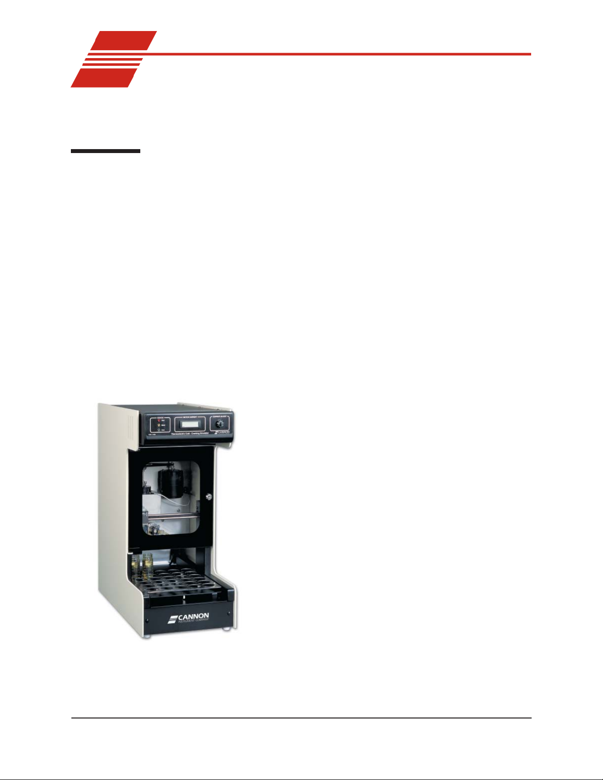
The CANNON® Cold-Cranking Simulator (CCS-2100) is a solid-state,
thermoelectrically-cooled, fully-automatic test instrument for the determination of cold-cranking viscosity of engine lubricants. The CCS-2100
operator initially loads oil samples into the Sample Tray and enters sample
identification via the computer keyboard or with a simple software
procedure restores a previously saved test configuration.
Without further operator intervention, the CCS-2100 tests and
determines the apparent viscosity for up to 30 test samples at
specified sub-ambient test temperatures, and records the
results.
New features
The CCS 2000 Series instruments offer several advantages
over previous CCS models, including improved temperature
management and elimination of the required warm-up sample
at the beginning of the test cycle. The thermoelectric system
also enhances cell cleaning with a warming cycle, improving
measurement precision. An attractive cabinet combines the
simulator mechanism and the modular CCS Series II Controller.
Applications
The CCS-2100 is used to determine the apparent viscosity of
engine oils at low temperatures at shear rates similar to those
at starting conditions of cold engines. CCS instruments are
found in quality control oil testing laboratories, major oil
corporation laboratories, independent test facilities, blending
facilities, and automotive corporation laboratories.
CANNON
Version 2.0a— November, 2010; CANNON
®
CCS-2100 with VISCPRO® Instruction & Operation Manual
2139 High Tech Road • State College, PA 16803 • USA
®
Instrument Company
Page 7

2
Precision
Temperature range
Viscosity range
Calibration constants
Equipment
The CCS-2100 is designed to produce measurements that meet or exceed
the accuracy and precision dictated in ASTM test method D 5293.
The CCS-2100/2100LT is capable of measuring the apparent viscosity of
oils at test temperatures ranging from -5°C to -40°C in increments of
5°C. The refrigerated water chiller must be set to +5°C to facilitate
operation of the thermoelectric cooling system.
The CCS-2100 is capable of calculating viscosity values ranging from 900
to 25,000 cP at test temperatures. Alternative ranges are possible.
Contact CANNON® technical services for more information.
The CCS-2100 will automatically calculate the appropriate calibration
constants (refer to Chapter 3 for more information). After calibration, the
CCS-2100 will use those constants for future tests without the necessity
of operator intervention.
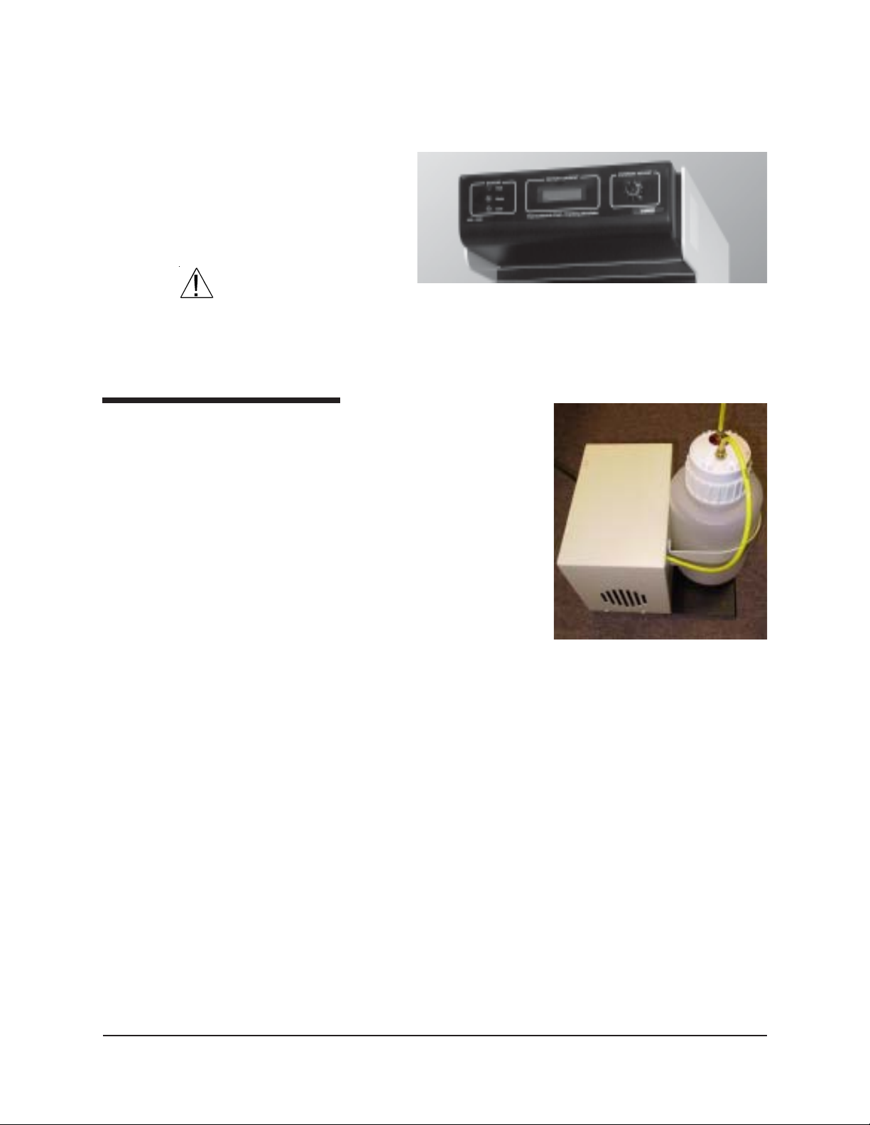
The CCS instrument includes a Simulator Mechanism and the integral
CCS Series II Controller. The peripheral waste system includes a vacuum
pump (for evacuation of the sample) and a waste container.
Simulator Mechanism
CCS Series II Controller
Waste system
The Simulator Mechanism contains a temperature-controlled rotor/stator
test mechanism and a constant metering, positive displacement piston
pump which transfers the oil samples from the sample bottles to the rotor/
stator assembly via an injection tube. The Simulator Mechanism also
includes a 30-position automatic X-Y Sample Table. The Sample Table
can process up to 30 sequential samples. The CCS-2100 automatically
accesses a new sample when the previous test is complete.
The CCS Series II
Controller translates
input from the CCS
sensors and transfers
the data to the computer for analysis. The
CCS Series II Controller also provides
power and relays
computer commands
to the Simulator
Mechanism.
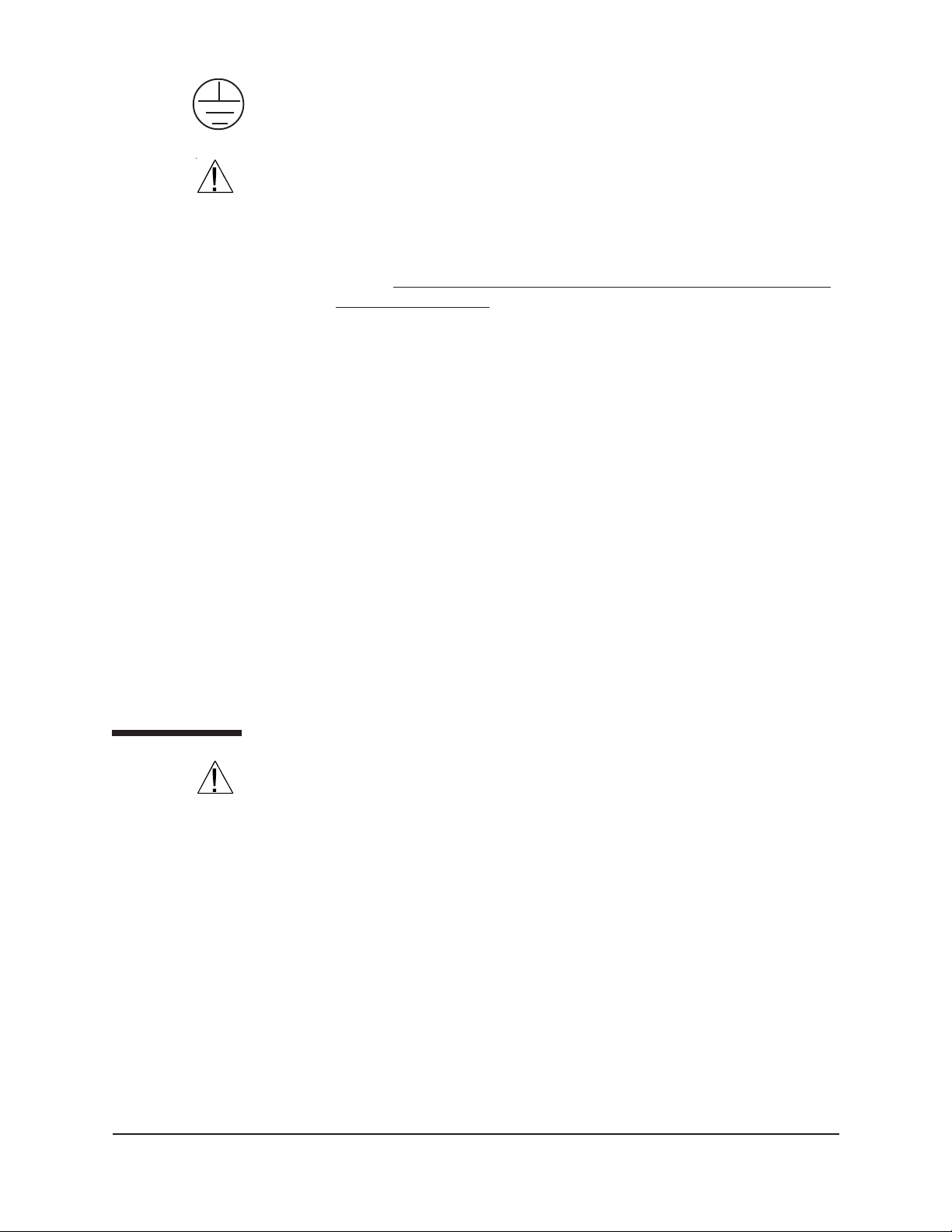
The waste system is
designed to eliminate
the need for solvent
cleaning. Used sample
is flushed from the
CCS rotor/stator assembly
rotor/stator with a
CANNON
Version 2.0a — November, 2010; CANNON
®
CCS-2100 with VISCPRO® Instruction & Operation Manual
2139 High Tech Road • State College, PA 16803 • USA
®
Instrument Company
Page 8
portion of the sample to be tested. The waste system includes the tubing
and connections from the CCS to the waste container and vacuum pump.
The pump is encased in a protective housing that includes a mounting
bracket for the large polypropylene waste container. The container is
capable of
holding waste
from approximately 45
sample tests.
3
CAUTION
The liquid level
in the waste
container should be checked frequently and the container should be
emptied prior to multi-sample tests.
Required accessories
The CCS requires a refrigerated
chiller capable of circulating a
distilled water mixture with 10
percent antifreeze to the CCS
thermoelectric system at a controlled
temperature of +5°C at a rate of at
least 1-2 liters/minute (see refrigerated chiller specifications, this
chapter). CANNON® recommends
and supplies a Julabo chiller for this
purpose. The CCS also requires an
IBM or IBM-compatible computer
and printer (request current specifications from CANNON) to run the
CCS software and produce printouts of the data collected by the CCS.
The CCS-2100 Series II Controller
The CCS waste system
CANNON
Version 2.0a — November 2010; CANNON
®
CCS-2100 with VISCPRO® Instruction & Operation Manual
2139 High Tech Road • State College, PA 16803 • USA
®
Instrument Company
Page 9

4
Utilities
The customer must be able to provide the appropriate power and grounding for the CCS.
AC power input
CAUTION
Grounding
Safety cautions
Specifications of the voltage and frequency of the AC power source for
the CCS are provided by the customer when placing an order. If you have
any questions regarding the correct voltage for your CCS model, call
®
CANNON
Only attach the power cord from the rear of the CCS Series II Controller
to an AC mains with the power requirements specified on the label on
the rear of the Controller.
for assistance.
It is very important that the power source for the CCS has an electrical
ground. The CCS is equipped with an IEC 320 socket which must be
plugged into a grounded outlet.
Please observe the following safety procedures and notices for proper
operation of the CCS:
Make sure that your unit is operated only by qualified personnel.
Make sure that you read and understand all operating instructions
and safety precautions listed in this manual before installing or
operating your unit. If you have questions regarding instrument
operation or documentation, contact CANNON
®
Instrument Company .
Do not deviate from the installation, operation or maintenance
procedures described in this manual. Improper use of the CCS
instrument may result in a hazardous situation and may void the
manufacturer’s warranty.
Handle and transport the unit with care. Sudden jolts or impacts may
cause damage to components.
Observe all warning labels.
Never remove warning labels.
Never operate damaged or leaking equipment.
Unless procedures specify otherwise, always turn off the unit and
disconnect the mains cable from the power source before performing
service or maintenance procedures, or before moving the unit.
Never operate the equipment with damaged mains power cables.
Refer all service and repairs to qualified personnel.
General Caution
In addition to the cautionary statements listed previously , additional
cautions may be posted throughout this manual. These cautions, identified by the caution symbol (see left) indicate important operational
procedures. Read and follow these important instructions. Failure to
observe these instructions may void warranties, compromise operator
safety , and/or result in damage to the CCS unit.
CANNON
Version 2.0a — November, 2010; CANNON
®
CCS-2100 with VISCPRO® Instruction & Operation Manual
2139 High Tech Road • State College, PA 16803 • USA
®
Instrument Company
Page 10
Protective Conductor
5
The Protective Conductor T erminal symbol is used to indicate required
ground connections for your instrument electrical supply .
WARNING
MAINS
~
AC Power Input Symbol
( O )
Supply OFF Symbol
Hazardous materials
When supplying power to this instrument, ensure that the protective
ground (earth) terminals of the instrument are connected to the protective
conductor of the (supplied) line (MAINS) power cord. Use only the
manufacturer-supplied power cord, which should be inserted in a socket
outlet (receptacle) which is also provided with a protective ground (earth)
contact.
Do not use an extension cord (power cable) without a protective
conductor (grounding).
The ~MAINS symbol indicates instructions or connections for the AC
power supply . The AC Power input must match the electrical specifications listed on the label on the rear panel of the instrument. The supplied
AC Mains power cord must be attached to the connector labelled
~MAINS. This connection serves as a means of disconnect and should be
readily accessible.
The (O) symbol indicates the OFF position for the electrical switches for
your unit (AC Mains or accessories).
Routine CCS operation may require the use and handling of hazardous
chemicals and solutions. CANNON® Instrument Company strongly
urges the operators and technicians working with the CCS to take proper
safety precautions when working with these materials. These safety
procedures can be found in the Material Safety Data Sheets which
accompany the solutions.
Unpacking
NOTE
CAUTION
CANNON
Version 2.0a — November 2010; CANNON
Some CCS components are quite heavy. To avoid injury, obtain necessary assistance when lifting and moving shipping cartons and heavier
unpacked components.
1. Carefully remove all components from their shipping cartons.
2. Consult the packing list to ensure that all items listed have been
received. The CCS is usually shipped in three packing crates (including the refrigerated chiller unit, if it is ordered from CANNON
3. Notify CANNON
®
Instrument Company if any items are missing.
4. Inspect all components for damage. Report any damage to the
shipping company and to CANNON
®
Instrument Company immediately . Remove any visible packing materials (packing foam, etc.)
from the components.
You should retain all packing materials until the CCS is connected and
functioning properly. If any component is returned to CANNON® Instru-
®
CCS-2100 with VISCPRO® Instruction & Operation Manual
2139 High Tech Road • State College, PA 16803 • USA
®
Instrument Company
®
).
Page 11

6
ment Company , it should be packed in it s original shipping container . You
must call CANNON® prior to returning any products (see warranty and
return information at the conclusion of this manual).
Positioning CCS components
1. Place the CCS on a stable laboratory bench or table.
2. Place the computer adjacent to the CCS.
3. Use the key provided to open the hinged door protecting the Simulator Mechanism.
4. Remove any pieces of foam packing that may have been included to
prevent shipping damage
to internal moveable
components.
5. Close the hinged door.
Sample Tray
6. Place the CCS-2100
Sample Tray on the
Simulator Mechanism
Sample Table so that the
arrow on the tray is
aligned with the arrow on
the left guide of the
Sample T able (see
photo). The gear on the underside of the Sample T ray must engage
the gear in the center of the base of the instrument. When the alignment is correct, the CCS sampler mechanism at its default position
(farthest left) will be centered over sample #1 on the Sample Tray.
Computer connections
Ensure that the computer specifications meet the minimum requirements
for your CCS instrument. These requirements are listed on the Computer
Specifications sheet provided with your Instruction & Operation Manual.
RS-232 serial connections
Locate the RS-232 (25-pin) CCS Control Cable. Connect one end to the
COM port on the rear of the computer . Connect the other end of this
cable to the socket on the rear of the CCS Series II Controller (note that
the connectors are “D” shaped, and fit only one way).
Sample Tray (top view) correctly
aligned on Sample Table (guides
CANNON
Version 2.0a — November, 2010; CANNON
®
CCS-2100 with VISCPRO® Instruction & Operation Manual
2139 High Tech Road • State College, PA 16803 • USA
®
Instrument Company
Page 12
Controller power distribution
7
Receptacle connections
2 3 4 6 7 8
1
9 10
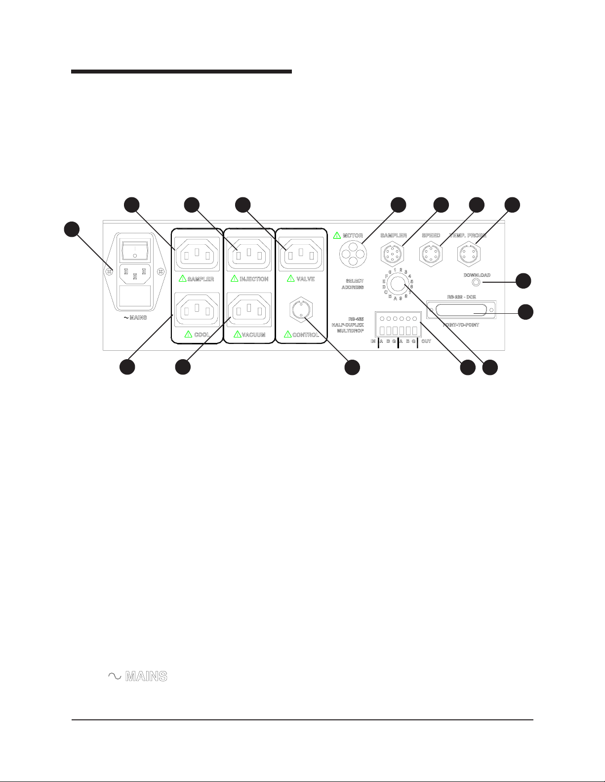
There are five AC power receptacles and one DC receptacle on the rear
of the CCS Series II Controller. The AC receptacles provide AC power
matching the AC mains input for the various CCS AC devices. The
Motor receptacle supplies regulated DC voltage for the rotor motor .
Power for the CCS Simulator Mechanism is supplied via the CCS Series
II Controller. AC Power cords from the CCS are labelled to match their
receptacles. Connect the power cords as follows:
5
15
14
1211 13
CCS Series II Controller rear panel with connections marked (see list below)
1. Mains power (to AC power source), ON/OFF switch and fuses
2. CCS sampler mechanism power connection
3. Injection pump power connection
4. Coolant valve power connection (unused)
5. CCS rotor motor power connection
6. CCS sampler control
7. Rotor speed sensor connection
8. CCS temperature probe connection
9. Thermoelectric cooling power connection to internal power
supply
10. Vacuum pump power connection
11. Thermoelectric cooling control (from stator assembly)
12. RS-485 connection (for multiple CCS instruments)
13. Address select (unused)
14. RS-232 serial connection (to computer COM port]
15. Download button (for future firmware upgrades—not used for
installation)
Mains
Make certain that the instrument power switch on the Controller rear
panel above the Mains power cord connection is turned off. Then attach
the Mains power cord from the Mains receptacle to the power supply
matching the label on the rear of the CCS unit.
CANNON
Version 2.0a — November 2010; CANNON
®
CCS-2100 with VISCPRO® Instruction & Operation Manual
2139 High Tech Road • State College, PA 16803 • USA
®
Instrument Company
Page 13

8
NOTES
Sampler
Injection pump
Cool
Vacuum pump
NOTE
Motor
Use only the CANNON®-approved supplied power cables for the CCS unit.
Do not use serial or power cables exceeding 3 meters in length. Do not
turn on the CCS power switch unless the chiller is attached and operating.
Connect the Sampler power cord from the Simulator Mechanism to the
SAMPLER receptacle on the CCS Series II Controller.
Connect the power cord from the INJECTION pump receptacle to the
Simulator Mechanism, at the receptacle labeled INJECTION.
Connect the power cord from the thermoelectric power supply to the
receptacle labelled COOL on the rear panel of the CCS Series II Control-
ler. This receptacle is energized whenever the controller power is ON.
Connect the power cord from the waste container vacuum pump to the
VACUUM pump receptacle on the Controller.
If an in-house vacuum is to be used to remove oil from the CCS, you
may omit the use of the waste container vacuum pump connection.
Connect the Simulator rotor motor power cord to the MOTOR recep-
tacle.
Control
RS-232
Valve
CAUTION
Do not connect any other cable to the MOTOR receptacle. The power
draw will damage the motor control circuit.
If it is not already attached, connect the control cable from the stator
thermoelectric cooling assembly to the CONTROL receptacle.
Connect the RS-232 serial cable from the computer COM port to the RS232 connector.
Optional connections for non-thermoelectric operation
The Valve connection (see photo image, page 7) is for optional nonthermoelectric cooling only—it is not used for normal thermoelectric
operation. The non-thermoelectric version CCS (earlier version) required
a custom-built rotor/stator assembly. If using a non-thermoelectric (older)
instrument, connect the power cord from the optional external solenoid
valve to the VALVE receptacle on the CCS Series II Controller. The
solenoid valve regulates coolant flow from the optional non-thermoelectric cooling device through the CCS cooling system.
CAUTION
Valve (or pump) voltage must match the CCS mains input voltage and
frequency. Use only CANNON®-approved supplied accessories in the
VALVE outlet. Do not circulate methanol refrigerants in thermoelectric
instruments!
CANNON
Version 2.0a — November, 2010; CANNON
®
CCS-2100 with VISCPRO® Instruction & Operation Manual
2139 High Tech Road • State College, PA 16803 • USA
®
Instrument Company
Page 14

9
NOTES
The solenoid valve may be obtained from CANNON® and must be
installed to the coolant return line by the customer. (In some cases, a
solenoid valve may already be included in the customer-supplied chiller.)
If the refrigerated chiller has a constant-running internal pump, it may not
be necessary to connect the pump to the CCS Controller.
Simulator Mechanism/Controller cable connections
Three cables from the Simulator Mechanism must be connected to the
matching receptacle on the rear panel of the CCS Series II Controller:
1. Connect the grey cable from the Simulator Mechanism speed sensor
to the SPEED jack on the CCS Series II Controller.
2. Connect the white temperature probe cable with the metal LEMO
plug to the matching TEMP PROBE jack on the Controller.
3. Attach the seven-pin connector cable to the seven-pin SAMPLER
jack on the Controller (see diagram, page 10). Connect the other end
of this seven-pin cable to the corresponding jack in the lower left
corner of the Simulator Mechanism rear panel.
4. Attach the four-pin connector cable from the thermoelectric cooling
unit to the CONTROL jack on the Controller (see diagram).
5. Set the Instrument Address on the rear panel of the CCS instru-
Tubing connections
Waste system connections
A short 1/4" yellow plastic tube links the sample/solvent waste container
with the waste container vacuum pump. This tube is taped to the vacuum
pump housing for shipping. Remove the tape and make certain that there
are no kinks in the vacuum hose. The longer tube should be attached
from the waste container to the CCS (see instructions below).
CAUTION
NOTE
The
severely damage the vacuum pump.
If an in-house vacuum is to be used to remove oil from the CCS, you
may omit the use of the waste container vacuum pump.
ment. Ordinarily the address should be set to "0". If other CANNON
instruments are to be controlled from the same computer, each
instrument must have a unique address. Each CCS requires a dedicated COM port.
waste container
must be connected properly or waste liquid may
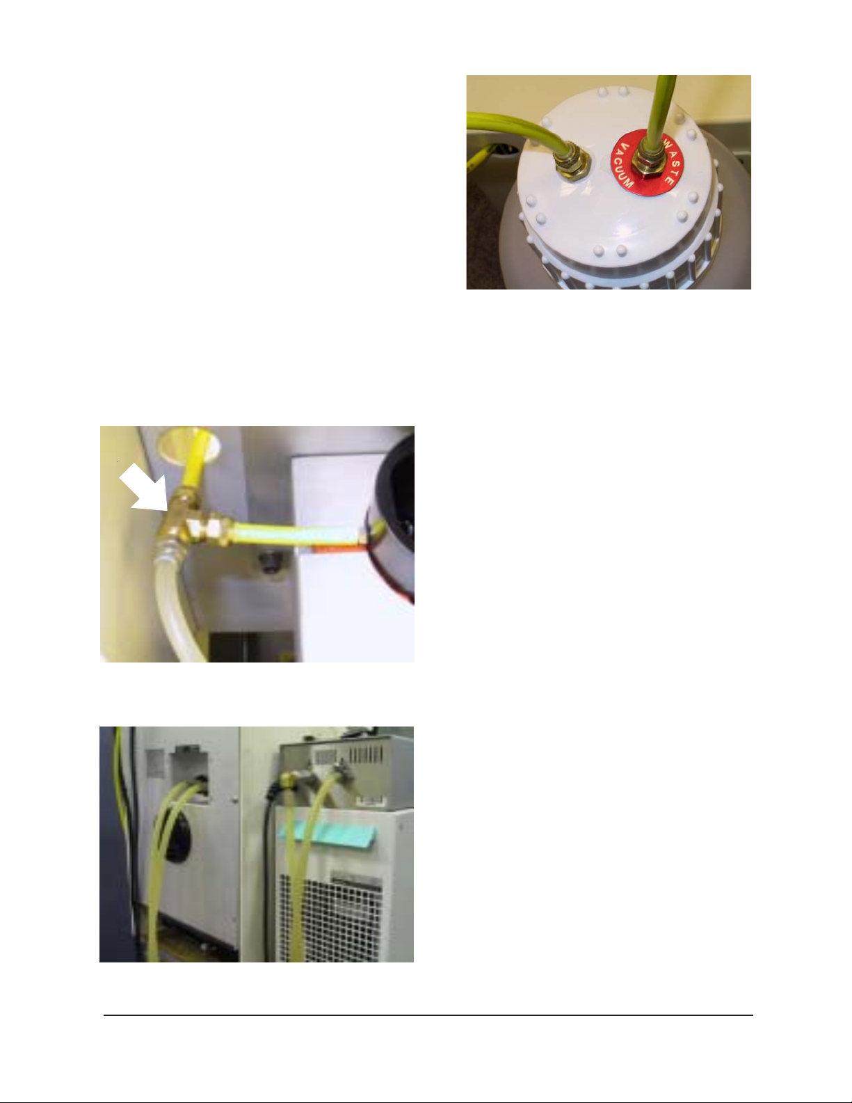
Connection procedure
1. If the shorter length of yellow tubing is not already attached to the
vacuum pump, it will be necessary to access the pump to attach it to
the Waste Vacuum connector by removing the six screws securing the
pump housing to the waste system assembly . After the housing has
CANNON
Version 2.0a — November 2010; CANNON
®
CCS-2100 with VISCPRO® Instruction & Operation Manual
2139 High Tech Road • State College, PA 16803 • USA
®
Instrument Company
Page 15
10
been removed,
connect one end of
the yellow tubing to
the fitting on the
vacuum pump.
Attach the other
end to the remaining fitting on the
waste container
(see photo, above).
2. Connect the longer
length of 1/4"
yellow plastic
tubing to the other fitting on the lid (this fitting includes a hose
extension which projects into the bottle).
3. Connect the other end of this longer tube to the vacuum fitting
mounted on the right rear panel of the Simulator Mechanism. This
"T" connection from viscometric cell to rear
panel waste container fitting
to
vacuum
pump
to
CCS unit
Waste container lid
fitting completes the vacuum connection to the CCS
viscometric cell (see photo).
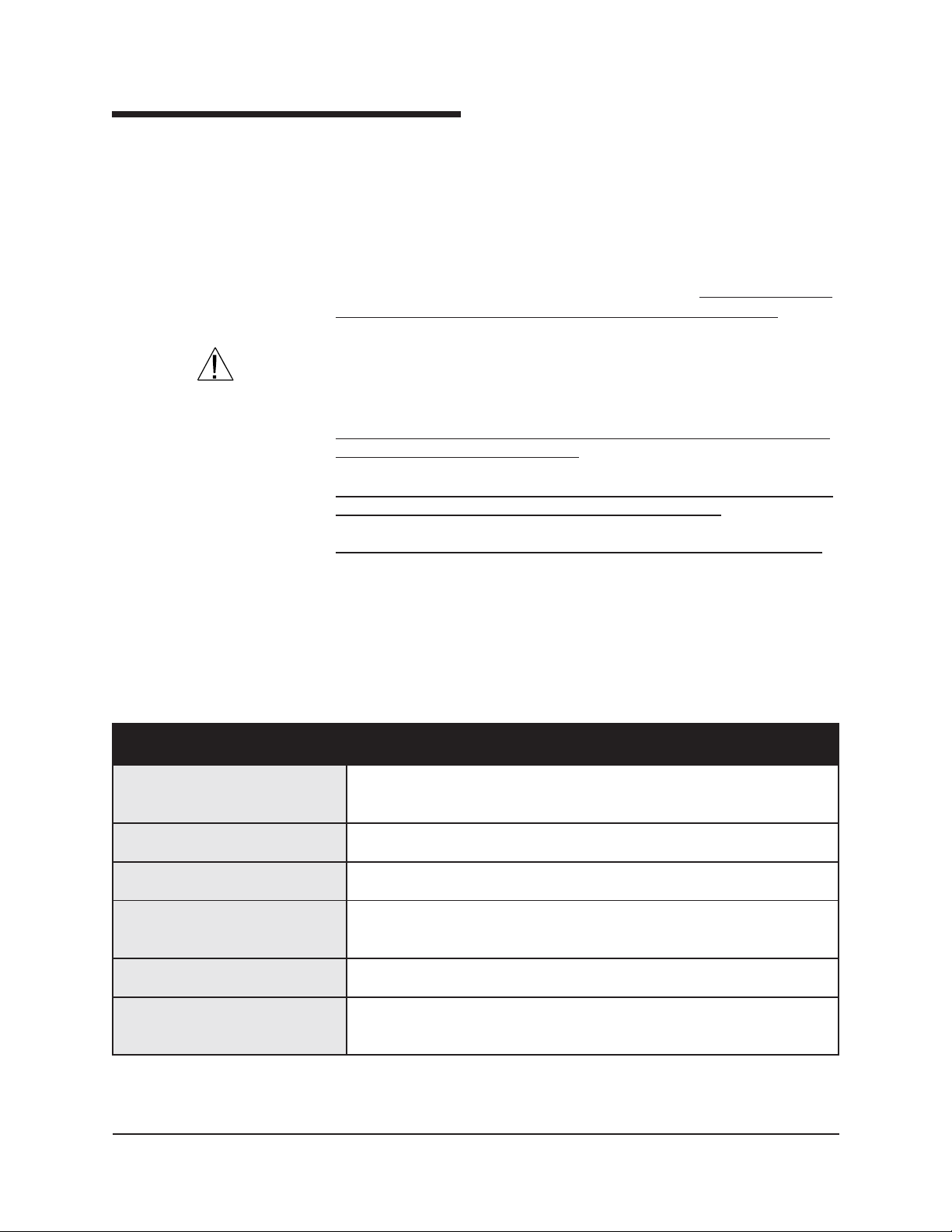
Coolant connections
There are two tubing connections on the rear of the
CCS housing. The fitting on the left is the coolant
INLET (for introducing the water/antifreeze mixture from the refrigerated chiller to the CCS) and
the fitting on the right of the rear panel is the
coolant OUTLET (for returning coolant to the
refrigerated chiller). Secure the ends of both hoses
to these fittings, then secure both hoses to the
appropriate bulkhead fittings on the refrigerated
chiller (see photo) using any connection hardware
provided with the tubing (if applicable). Route the
hose from the CCS OUTLET to the refrigerated
chiller INLET, and the hose from the CCS INLET
to the refrigerated chiller OUTLET.
Refrigerated chiller coolant connections
CANNON
Version 2.0a — November, 2010; CANNON
®
CCS-2100 with VISCPRO® Instruction & Operation Manual
2139 High Tech Road • State College, PA 16803 • USA
®
Instrument Company
Page 16
Filling the refrigerated chiller
Check the operations manual for the refrigerated chiller to determine its
capacity . Then obtain the necessary volume of water and high-quality
automotive antifreeze (ethylene glycol) necessary to provide a mix with a
ratio of 10 percent antifreeze to 90 percent water. After you have secured
the refrigerated chiller tubing connections to the CCS instrument (see
previous section) add the necessary quantity of water/antifreeze mixture
to the refrigerated chiller. The modified Julabo refrigerated chiller
includes a sight glass for monitoring the liquid level.
the temperature for the circulating coolant should be set at +5°C.
11
For CCS operation,
CAUTION
NOTE
Ethylene glycol is a toxic substance. Use proper safety precautions
when handling. Follow appropriate MSDS procedures.
Ensure that the chiller is connected to the CCS and functioning properly
before providing power to the CCS.
The water-antifreeze mix should be replaced annually for reliable performance and to prevent corrosion of internal components.
Do not set the chiller temperature below the freezing point of water (0°C).
Depending on the amount of fluid displacement in the coolant lines, it
may be necessary to add additional antifreeze/water mixture to the
refrigerated chiller when the unit commences operation. Monitor the
liquid level in the refrigerated chiller during normal operation. If air
bubbles are consistently visible in the coolant lines, add additional
mixture until the refrigerated chiller is full.
EPYT obaluJA.erusserpcirehpsomtaotnepo,)delaestontub(riovreserdesolC
SNOITACIFICEPSRELLIHCDETAREGIRFERDERIUQER
sirellihcdeifidom
.NONNACmorfelbaliavadnadednemmocer
MUIDEMGNILOOC ezeerfitnatnecrep01htiwretawdellitsidfoerutxiM
YTICAPAC
ETARWOLFPMUP 1ta.nim/)strauq1.2-1(sretil2-1tsaeltAdaehfo)sehcni93(retem
SENILGNILOOC ni)sehcni5.-52.0(mm21-6,htgnelni)sehcni93(retem1yletamixorppA
YTICAPACLAVOMERTAEH C°5+tasttaw002tsaeltA
ERUTAREPMETWOL
C°5+taniatniamdnalortnoC
retemaid
CANNON
Version 2.0a — November 2010; CANNON
®
CCS-2100 with VISCPRO® Instruction & Operation Manual
2139 High Tech Road • State College, PA 16803 • USA
®
Instrument Company
Page 17

12
Installing VISCPRO® software
VISCPRO® is a powerful new software product providing a generic
instrument interface for controlling and operating your CANNON
instrument via computer. VISCPRO® also includes reporting/analysis
modules for processing and displaying sample data.
T o install the VISCPRO
sequence presented. Make certain that you complete the sections on
checking instrument settings and calibration data. If you encounter
difficulties at any stage in the installation process, call CANNON
T echnical Services at 814-353-8000.
Windows® installation
1. Turn on your computer. Wait for the Windows® software to load.
2. From the Windows
3. Double-click the Add/Remove Programs icon and follow the
Installation actions
The installation program will:
create a directory for your data files. The default directory is
write SETUP information to the Windows
copy the software executable file and other necessary files to the
update other files in your Windows
place a shortcut icon for the VISCPRO
®
®
software, follow the instructions below in the
®
®
Start Bar click Settings/Control Panel. Insert
the first VISCPRO® installation disk or CD-ROM into the disk drive.
Windows prompts to complete the installation procedure. The
executable file for VISCPRO
®
software installation is SETUP.EXE.
C:\Program Files\Cannon Instrument\VISCPRO).
®
registry.
directory you specify.
®
directories to versions fully
compatible with the current VISCPRO® software.
®
executable file on your
Windows
®
desktop.
CANNON
Version 2.0a — November, 2010; CANNON
®
CCS-2100 with VISCPRO® Instruction & Operation Manual
2139 High Tech Road • State College, PA 16803 • USA
®
Instrument Company
Page 18

Specifications
SNOISNEMID mm001tsaeltadda(peed)"62(mm066×ediw)"8/1-31(mm333×hgih)"82(mm117
THGIEW fi(tinugniloocobaluJrof).sbl09(gk14/tinuyramirp0012-SCCrof).sbl531(gk16
THGIEWGNIPPIHS 521(gk75;seirosseccadnatinuyramirp0012-SCCrof).sbl462(gk021yletamixorppA
morfdesahcrup NONNAC
)noitallatsnirofhtpedot)"4(
®
(tinugniloocobaluJrof).sbl NONNAC
morfdesahcrupfi
13
SNOITACIFICEPS0012-SCC
seirosseccarof).sbl56(gk03;)
®
)
LACIRTCELE W0001,zH06/05,%01±CAstlov511/001:0012-SCC#ledoM
GNITAREPO
SNOITIDNOC
GNITARESUF mm02x5,A4V052M:tinutlov032;mm02x5,A8V052M:tinutlov511/001:rellortnoC
ECNAILPMOC ,CDV0091(TOP-IH,)CEE/32/37(evitceridegatlovwoL;)CEE/633/98(evitceridCME
W0001,zH06/05,%01±CAstlov032:F0012-SCC#ledoM
2eergednoitulloP,IIyrogetaCnoitallatsnI,gnisnednoc-nonHR%09-%01,C°03-°51
).ces06
.tinuruoyhtiwdeilppusdrocrewopdevorppaehtylnoesU
CANNON
Version 2.0a — November 2010; CANNON
®
CCS-2100 with VISCPRO® Instruction & Operation Manual
2139 High Tech Road • State College, PA 16803 • USA
®
Instrument Company
Page 19

14
This page intentionally left blank.
CANNON
®
CCS-2100 with VISCPRO® Instruction & Operation Manual
Version 2.0a — November, 2010; CANNON
2139 High Tech Road • State College, PA 16803 • USA
®
Instrument Company
Page 20

CHAPTER
Configuring the CCS
2
This chapter contains information on configuring the CCS instrument for
successful operation. Additional configuration information may be found
in a separate document, CCS Installation Notes, provided with your CCS
instrument or software upgrade.
Checking/editing configuration settings in VISCPRO
15
Original installation
CAUTION
Configuration protection
Your original software installation package may have included preset
instrument configuration data on an accompanying floppy disk. This
information should be copied to the VISCPRO® directory on your
computer immediately following initial installation of the VISCPRO
software. Consult the CCS Installation Notes for further information.
Copying or recopying floppy disk information to your VISCPRO® directory will overwrite existing sample data. If you wish to retain a record of
previously-saved configurations, make certain to archive your existing
sample data before doing so (see Chapter 11 for information on using
the Database Manager software).
Follow the procedures in this chapter and the chapter on CCS calibration
to verify/edit the instrument and calibration settings to ensure that they
conform to the actual characteristics of your CANNON® instrument.
T o check the configuration settings for your instrument(s), you must log
in to the security system as a manager. The software is installed with a
default Manager account. This account has no password, allowing any
operator access to manager-level software functions as long as the
password is not activated/changed. If you would like to engage the fullrelease security options, see Security Options in Chapter 5 for instructions.
®
Running the software
Logging in
CANNON
Version 2.0a— November, 2010; CANNON
2139 High Tech Road • State College, PA 16803 • USA
T o start the VISCPRO® software program, double-click the VISCPRO
icon on your Windows® desktop (Windows® NT® users can click Start/
Programs/VISCPRO/VISCPRO.EXE).
1. Use your mouse to click Main from the VISCPRO® menu bar.
2. Click Log In from the Main menu options.
3. Click on the
to display the list of registered users.
4. Click Manager. It is not necessary to enter a password.
®
CCS-2100 with VISCPRO® Instruction & Operation Manual
(arrow) on the right side of the User Name: list box
®
Instrument Company
®
Page 21

16
5. Click OK to complete the Log In procedure.
NOTE
For more information on VISCPRO security options, see page 40.
Checking/editing Instrument Settings
1. Use your mouse to click (select) Configure from the VISCPRO
menu bar (see graphic, next section).
2. Select your instrument from the list of available instruments (there
may be only one instrument in the list).
3. Select option 2, Instrument Settings, from the list of configuration
options. The Instrument Settings window will appear.
You will use the Instrument Settings window (see below) to describe
and control CCS instrument operational features. These settings affect the
instrument as a whole. Check the instrument settings for your CCS per
the instructions below , and make any necessary changes:
®
The Instrument Settings window
CANNON
Version 2.0a — November, 2010; CANNON
®
CCS-2100 with VISCPRO® Instruction & Operation Manual
2139 High Tech Road • State College, PA 16803 • USA
®
Instrument Company
Page 22
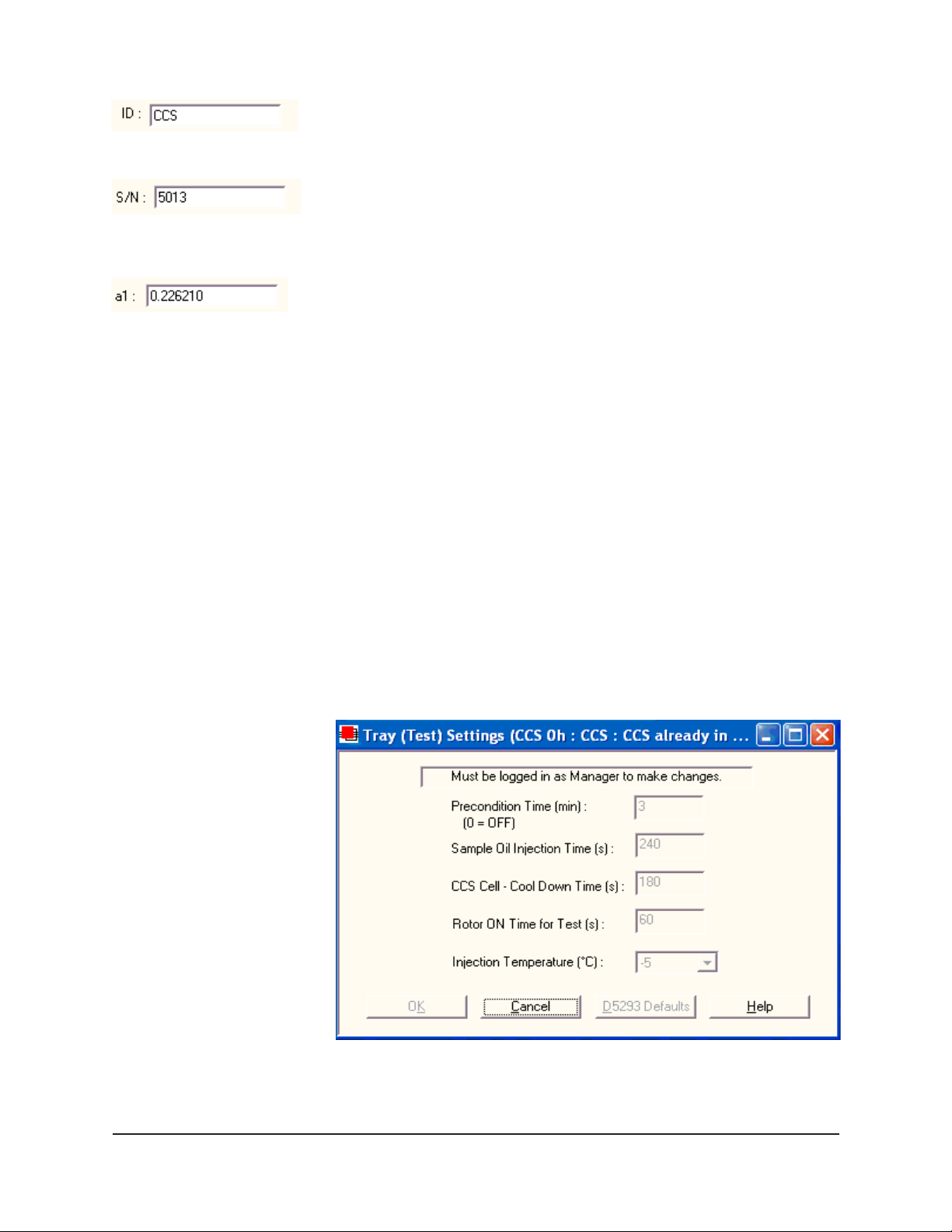
Use the ID field to input instrument identification information using up to
30 alphanumeric characters.
The S/N: field should correspond to the four-digit serial number from the
label on the CCS rear service panel.
The probe constant values (a0, a1, and a2) must be identical to the values
on the calibration certificate provided with your temperature probe.
Verify that the values correspond.
Note that firmware and communication port settings are automatically
determined. These values cannot be altered from this window.
When you have verified all settings for all editable fields, click OK.
Viewing/editing other setup information
If your instrument has already been set up by a technician, you can use
the instructions in this section of the manual to check or, if necessary,
change the instrument settings.
17
1. Click Configure from the VISCPRO® menu bar .
2. Select your instrument from the list of available instruments.
3. Select Tray (Test) Settings from the list of configuration options.
The Tray (Test) Settings window will appear.
The Tray (Test) Settings window
CANNON
Version 2.0a — November 2010; CANNON
®
CCS-2100 with VISCPRO® Instruction & Operation Manual
2139 High Tech Road • State College, PA 16803 • USA
®
Instrument Company
Page 23
18
The T ray (Test) Settings window contains setup information for your
instrument. Default test settings (which may be restored at any time by
clicking the Defaults button) are specified in ASTM D 5293. In certain
circumstances, the user may wish to alter these settings. For more information, see Tray (Test) Settings in Chapter 5.
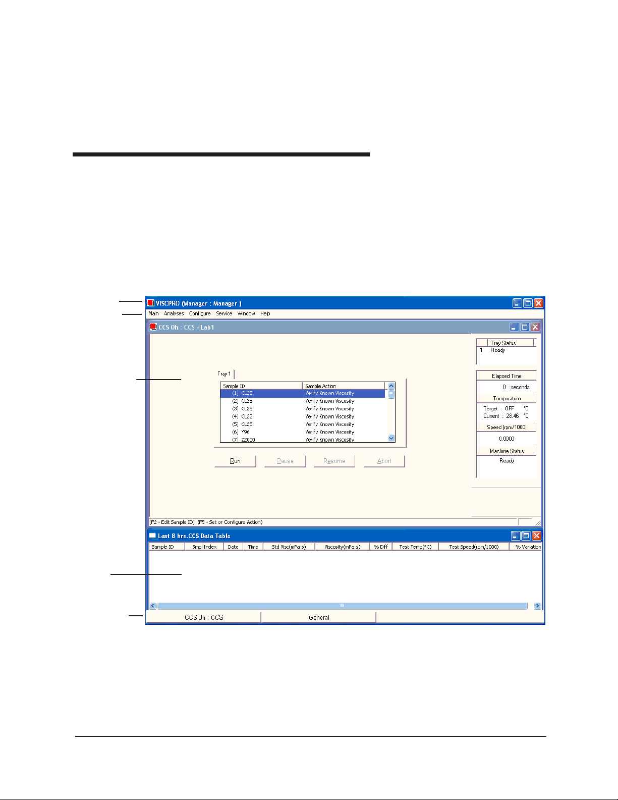
VISCPRO software interface elements
Title Bar
Menu Bar
Instrument
View window
The VISCPRO® primary display window is framed on the top by the
VISCPRO
®
title bar and menu bar, and on the bottom by the VISCPRO
status bar. The application window is usually preconfigured to include
two child windows. The first is an Instrument View window, which
®
describes your CANNON
instrument and provides controls for CCS
testing, and the second is an analysis window that displays data from
CCS tests.
®
Analysis
window
Status bar
The VISCPRO® primary display
CANNON
Version 2.0a — November, 2010; CANNON
®
CCS-2100 with VISCPRO® Instruction & Operation Manual
2139 High Tech Road • State College, PA 16803 • USA
®
Instrument Company
Page 24
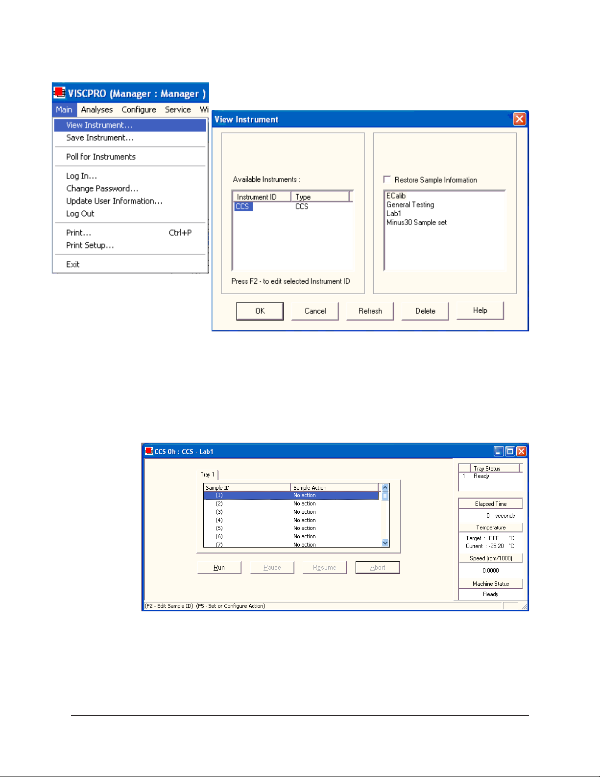
19
NOTE
If the Instrument View window does not appear, click View Instrument
from the Main menu:
The View Instrument window
Then click the desired instrument from the list of available instruments
and click OK. If the Available Instruments list box is blank, your CCS
instrument may not be on-line. Check cable connections and make
certain the instrument is ON.
The Instrument View window
CANNON
Version 2.0a — November 2010; CANNON
®
CCS-2100 with VISCPRO® Instruction & Operation Manual
2139 High Tech Road • State College, PA 16803 • USA
®
Instrument Company
Page 25
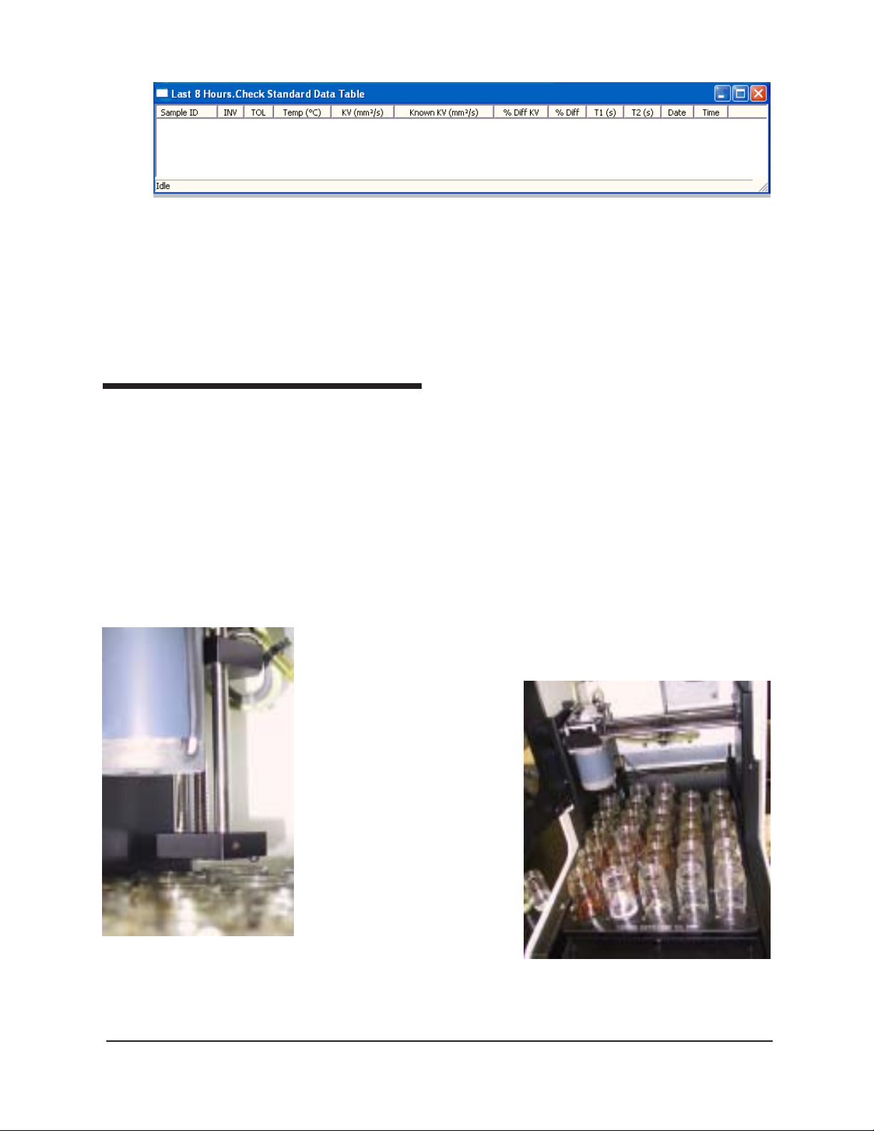
20
The CCS Data Table window
NOTE
To change the Tray (Test) Settings for your instrument(s), you must log in
to the security system as a manager.
4. Edit the values for Tray (Test) Settings as necessary. When done,
click OK to save current values and exit the Tray (Test) Settings
window.
Initial Stepper Motor Service
Prior to performing instrument actions with the CCS-2100 Automatic
Cold-Cranking Simulator, you must first home the Sample Tray mechanism as follows:
1. Make certain that the chiller is connected and operating properly .
Then turn the CCS instrument is ON.
2. Load the VISCPRO software by double-clicking the VISCPRO
on your W indows® desktop (Windows® NT® users can click Start/
Programs/VISCPRO/VISCPRO.EXE).
3. Click Service from the menu bar and select your CCS instrument
from the list.
4. Select Stepper Motor Service from the Service options.
®
icon
CCS sampler mechanism
with tube in home position
(raised)
CANNON
Version 2.0a — November, 2010; CANNON
5. Click on the Tube Up
button until the tube has
reached the top of its
travel.
6. Ensure that the arrow on
the Sample Tray is aligned
with the arrow on the
Sample T able (Table
Forward/Table Back
buttons).
7. Click on the Trolley Left
button until the sampler
has reached the limit of its
travel. If the Sample Tray
has been aligned properly ,
the sampler should now be
CCS-2100 with tray in home posi-
centered over the #1
sample position.
®
CCS-2100 with VISCPRO® Instruction & Operation Manual
2139 High Tech Road • State College, PA 16803 • USA
®
Instrument Company
Page 26

8. Click the Set Home Flag button. Note that the button will disappear
when the home flag has been set successfully . Then click
close the window .
Setting the CCS Set Motor Current
The CCS Motor Current window in VISCPRO® provides the software
interface for adjustment of the CCS motor current. To set the CCS motor
current:
1. Select the Set Motor Current option from the Service menu. The
Set Motor Current Service window will appear.
2. Prepare a 60 ml bottle of CANNON
place it in position 1 of the Sample Table. Then press the Start
button. The CCS will begin the current adjustment procedure.
3. When the rotor/stator has reached the correct temperature, the
software will prompt you to adjust the CCS motor current using the
dial on the front panel of the Control Unit. Adjust the current until
the value in the Speed: field of the Motor Current Service window
indicates a rotor speed of 240 rpm.
to
®
CL25 viscosity standard and
21
The Set Motor Current Service window will continue to display cell
temperature and cell motor speed. When you have completed the rotor
speed adjustment procedure, press the Close button to exit the Set
Motor Current Service window. To terminate the Set Motor Current
Service process at any time, click Finished.
CANNON
Version 2.0a — November 2010; CANNON
®
CCS-2100 with VISCPRO® Instruction & Operation Manual
2139 High Tech Road • State College, PA 16803 • USA
®
Instrument Company
Page 27

22
This page intentionally left blank.
CANNON
®
CCS-2100 with VISCPRO® Instruction & Operation Manual
Version 2.0a — November, 2010; CANNON
2139 High Tech Road • State College, PA 16803 • USA
®
Instrument Company
Page 28

CHAPTER
3
Calibration is essential for the proper operation of the CCS. The CCS is
calibrated before it is shipped to the customer; however, the CCS should
be recalibrated after installation. Frequency of recalibration is at the
discretion of the user.
The CCS calibration procedure ensures that the mathematical constants
used in calculation of viscosity from CCS measurements accurately
reflect the unique properties of the CCS rotor/stator mechanism.
Calibration procedure
During calibration, the software uses calibration standard data from CCS
tests of viscosity standards to perform the mathematical calculations
necessary to derive three calibration constants– b0, b1 and b2. Then the
program displays the new constants and recomputes a viscosity (in cSt)
for each of the calibration standards. The resulting viscosity calculation is
compared with the known viscosity of the standard and displayed on the
computer screen.
23
CALIBRATING THE CCS
NOTES
The software allows the operator to manually change the constants if
necessary to more closely match actual and calculated viscosities.
A calibration must be performed for each temperature at which samples
will be tested.
Preparing/updating the list of calibration standards
During installation of your VISCPRO® software package, a list of current
CANNON CL standards (see table, next page) is automatically loaded
into the VISCPRO® database. Before testing calibration standards, it will
be necessary for you to enter the viscosity data from the standard bottles
into the VISCPRO® program using the following procedure:
1. Click Configure from the VISCPRO® primary display and select
your CCS instrument.
2. Click CCS Calibration Standards from the Configure menu
options. The CCS Calibration Standards window will appear (see
graphic, following).
3. Assemble your calibration standards and input the viscosity data (in
mPa·s) from the standard bottles for each CL standard and temperature in the appropriate fields. If you have additional standards,
including user-defined standards, you can enter these by right-
CANNON
Version 2.0a— November, 2010; CANNON
®
CCS-2100 with VISCPRO® Instruction & Operation Manual
2139 High Tech Road • State College, PA 16803 • USA
®
Instrument Company
Page 29

24
clicking your mouse in the Sample ID field and selecting the Insert
New option . To delete an unused standard, right-click your mouse in
the Sample ID field and select Delete.
®
NONNAC
-itarbilaC
liOno
C°5- C°01- C°51- C°02- C°52- C°03- C°53-
080LC 009
090LC 0021
001LC 0090071
011LC 05510052
021LC 00800610023
031LC 005100920584
041LC 008006105230007
051LC 0071007200640508
061LC 0052005500011
071LC 054105220073003600311
091LC 00810053004700071
002LC 776105620034055700731
022LC 00310052001500111
042LC 0522006300060070100891
052LC 00810053004700271
062LC 057100720044005700431
082LC 0031005200050039
003LC 0042057300160050100391
023LC 00810053003700951
043LC 00720024000749121
083LC 0092008500031
024LC 0025005850441
084LC 00320054005900012
035LC 0006348918861
006LC 0073003700651
086LC 0559
047LC 000600021
erutarepmeT
SDRADNATSNOITARBILAC
detacidnItaytisocsiVlanimoNetamixorppA
NOTE
A minimum of five oils are required for calibration at each temperature in
accordance with ASTM D 5293- 08.
CANNON
Version 2.0a — November, 2010; CANNON
®
CCS-2100 with VISCPRO® Instruction & Operation Manual
2139 High Tech Road • State College, PA 16803 • USA
®
Instrument Company
Page 30
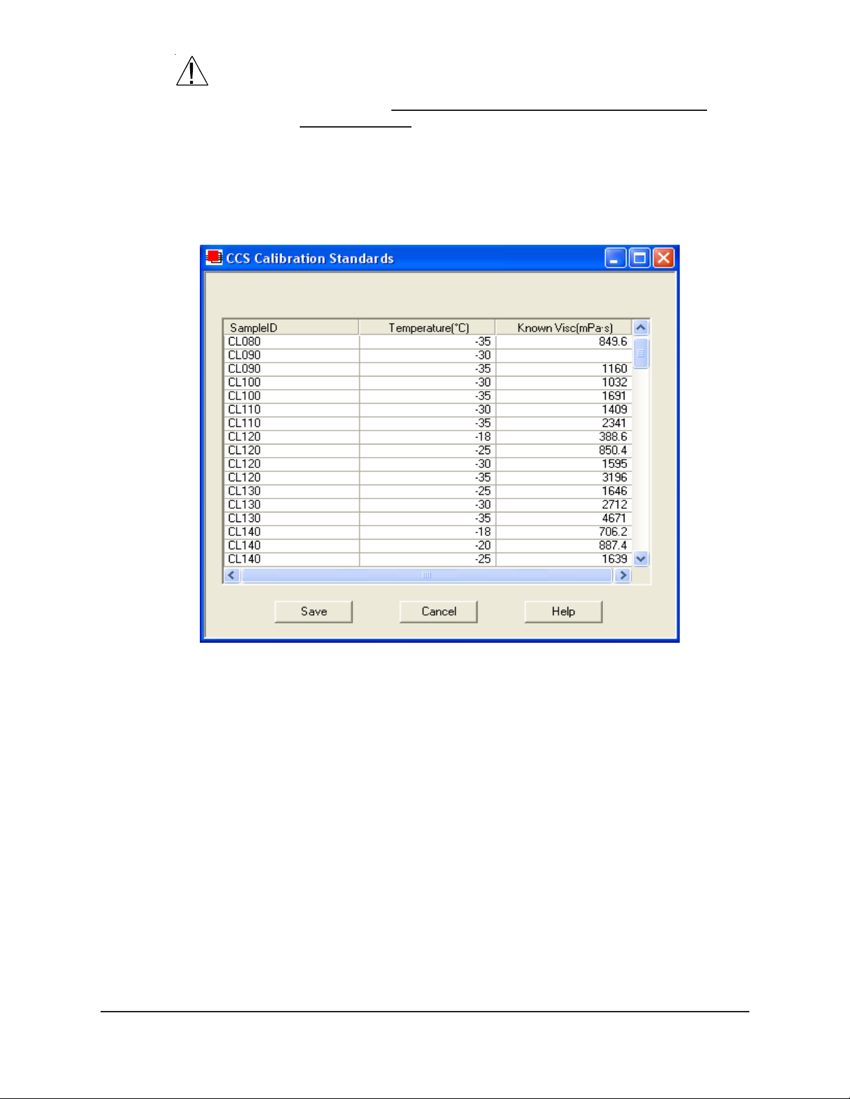
25
CAUTION
Make certain to verify the Known Viscosity (calibration standard viscosity
in mPa·s) in the calibration list BEFORE testing selected standards (see
next sections). Incorrect or outdated viscosity data may skew future
calibration results.
4. After you have entered all ID, temperature and viscosity information
into the CCS Calibration Standards list (see graphic), click the
SAVE button to save the data and exit the window.
Testing calibration standards
Selecting standards
The CCS Calibration Standards list window
T o calibrate the CCS instrument, it is first necessary to test samples of
known viscosity at the desired calibration temperatures.
1. Assemble a group of CANNON® standard oils with known viscosi-
ties for calibration. Refer to the table on the previous page when
choosing the appropriate CL standards.
2. Click Configure from the VISCPRO
your CCS instrument.
3. Click CCS Choose Calibration Standards from the Configure
menu options. The CCS Choose Calibration Standards window
(see graphic, next page) will appear.
4. Click the desired standards to select them for calibration. A check
mark indicates that the standard has been selected.
CANNON
Version 2.0a — November 2010; CANNON
®
CCS-2100 with VISCPRO® Instruction & Operation Manual
2139 High Tech Road • State College, PA 16803 • USA
®
®
primary display and select
Instrument Company
Page 31

26
NOTE
NOTE
The Choose Calibration Standards window
5. After the desired standards have been selected, click the desired
temperatures for calibration. Then click Generate List. The
VISCPRO software will automatically create a calibration test
sequence using the standards you selected and display the test
sequence in the Instrument View window .
To open a window displaying the complete list of samples to be tested,
along with the test temperatures for each sample, click CCS Sample List
Service from the Service menu.
6. Prepare the instrument and calibration standards in the same manner
as you would prepare samples for viscosity testing (see next chapter).
CCS-2100 users should place the standards in the sample table in the
test sequence indicated, and (if necessary) execute the Stepper Motor
Service (see page 19) to home the sampler mechanism.
7. T o initiate the calibration test sequence, click Run from the Instru-
ment View window. The instrument will begin testing with the first
sample in the test sequence. At the conclusion of testing, the sampler
mechanism for the CCS-2100 will return to the home position.
CANNON
Version 2.0a — November, 2010; CANNON
®
CCS-2100 with VISCPRO® Instruction & Operation Manual
2139 High Tech Road • State College, PA 16803 • USA
®
Instrument Company
Page 32

Performing the calibration
After valid calibration data has been obtained by testing calibration
standards, the CCS instrument may be calibrated using the following
procedure:
1. Use the VISCPRO
in order to access the calibration menu.
2. Click Configure from the VISCPRO
your CCS instrument.
3. Click Calibration. The Calibration window will appear.
®
software to log on as a Manager (Main/Log In)
®
primary display and select
27
CCS Calibration window
4. Select the desired calibration Test T emperature. If calibration
constants are known, they may be input manually in the appropriate
fields and saved by clicking Save New Constants. If test data from
calibration standards is to be used, select the desired date range for
CANNON
Version 2.0a — November 2010; CANNON
®
CCS-2100 with VISCPRO® Instruction & Operation Manual
2139 High Tech Road • State College, PA 16803 • USA
®
Instrument Company
Page 33

28
acceptable calibration data by using the No older than [x] hours spin
controls to set the date search parameters. Any calibration
standards successfully tested during the time frame you specified will
appear in the window list box.
NOTE
Selecting samples
NOTE
Saving new constants
Standards which were not within 0.05°C of the desired test temperature
during the test, according to temperature probe readings, will not be
displayed in the calibration window.
5. Select (or deselect) the specific sample entries you desire to use for
calibration from the displayed list by clicking on them to highlight
them. To select a range of samples, click on the first sample, then
press and hold the S key while clicking the last sample. To
select several individual samples for calculation, hold down the C
key while clicking the desired samples to select (or deselect) them.
You must select at least four sample entries or the software will not
recalculate the constants.
6. When the desired samples have been selected, click on Calculate
New Constants. The new constant(s) b0, b1 and b2 will be dis-
played in their respective fields in the window .
7. If the new calibration constants are acceptable (see next section),
click on Save New Constants to save the constants for the current
instrument. If the difference is not within acceptable limits, review
the calibration information more closely and select a different range
of standards for inclusion in the calibration routine.
8. Repeat steps 4-7 until a satisfactory calibration result is obtained for
each calibration temperature. If you are unable to calibrate successfully , refer to Chapter 6 for CCS maintenance/service information.
9. Click Close to exit the Calibration window. Test several standards
to verify a successful calibration.
Checking calibration accuracy
It is very important to check the accuracy of the calibration procedures
since any small errors in calibration could result in faulty viscosity
readings and erroneous data. The calibration window (see previous page)
provides vital calibration data including:
Test Visc[osity]: The viscosity of the standard (from the bottle label)
Calc Visc[osity]: The CCS-calculated viscosity for the standard
using the current calibration constants.
ReCalc Visc[osity]: The CCS-calculated viscosity for the standard
as calculated using the calibration constants derived from currentlyselected calibration data in the calibration window.
CANNON
Version 2.0a — November, 2010; CANNON
®
CCS-2100 with VISCPRO® Instruction & Operation Manual
2139 High Tech Road • State College, PA 16803 • USA
®
Instrument Company
Page 34

% Diff[erence]: The percentage difference between the Known
Visc[osity] and the Recalc[ulated] Visc[osity] as determined by the
formula:
%Diff =
Recalc Viscosity
(
[
Test Viscosity
) - 1
100
*
]
%Var: An indicator of rotor speed variation during the last 5 seconds
of each sample/standard run. This value is determined by the equation:
22
x5x
−∑
29
*100Var%
=
5
x
Where: x = { set of the last 5 seconds of speed readings}
You may evaluate the accuracy of the new calibration constants by
comparing the Known Visc[osity] for the standard with the
Recalc[ulated] Visc[osity] for each standard selected for the new
calibration. This difference is displayed as a percentage in the last
column (% Diff) of the updated sample list box.
_
x = mean of x
2
Σx
= sum of x
2
R: The displayed value is an indicator of how well the raw data fits
the calibration equation using the newest calibration constants. A
“perfect fit” value is 1.0000. CANNON recommends an “R” value in
excess of 0.9. Acceptable values will vary depending on the user’s
application.
Std. Dev (visc. * speed): The displayed value indicates viscosity
times rotor speed in the quadratic equation:
N * n = b0 + (b1*N) + (b2*N
Where N = rotor speed and n = viscosity
2
)
Recalc with constants
Saving new constants
NOTES
The Recalc with constants option will recalculate the %Diff[erence]
value using constants input manually by the user. To use this option,
input the desired constants in the appropriate fields and then press the
Recalc with constants button.
When you are satisfied with the calibration, click the Save New Con-
stants button. Then click Close to exit the Calibration window.
Once the Save New Constants button is pressed, the updated calibration
constants are associated with the selected instrument, and will remain
the same regardless of the instrument configuration defined for that
instrument.
You must click Save New Constants if you wish to save the new calibra-
tion constants.
T est several standards to verify a successful calibration.
CANNON
Version 2.0a — November 2010; CANNON
®
CCS-2100 with VISCPRO® Instruction & Operation Manual
2139 High Tech Road • State College, PA 16803 • USA
®
Instrument Company
Page 35

30
Viewing current calibration constants
T o view current calibration constants for your instrument, click Current
Cell Calibration Constants from the Configure menu.
The Current Cell Calibration Constants window will be displayed.
The Current Cell Calibration Constants window
Saving a calibration
When calibration is complete, the calibration information is only saved to
the current instrument configuration. This calibration information will
remain in effect until the instrument is recalibrated at that same temperature, or until instrument and tray settings from a previously-saved
instrument configuration are restored.
T o avoid losing valid calibration data, CANNON® recommends saving
the instrument configuration settings immediately after completing a new
calibration (see Saving a configuration). The name for the instrument
configuration should identify the specific instrument, the calibration
time, and the temperature(s):
EXAMPLE:
1-10-02 at -20 for CCS
After the instrument configuration has been saved, calibration data may
be restored at any time using the View Instrument option from the Main
menu. Note that the Restore Instrument Settings must be selected to
restore calibration data.
NOTE
The Restore Instrument Settings option is security-protected at the
Manager level (see manual instructions regarding security).
CANNON
Version 2.0a — November, 2010; CANNON
®
CCS-2100 with VISCPRO® Instruction & Operation Manual
2139 High Tech Road • State College, PA 16803 • USA
®
Instrument Company
Page 36

CHAPTER
4
31
TESTING SAMPLES WITH THE
CCS
This chapter of the manual will provide information on testing samples
using the CCS instrument.
®
controlling software offers the advantage of multi-
NOTE
The VISCPRO
sample testing for up to 30 samples. Sample data is automatically stored
to the VISCPRO® database for reporting and data collection. Additionally, several reports (analyses) may be used to calculate and display
viscosity values. All analyses provide a dynamic operation mode which
can immediately display and transmit test results to your computer
screen, printer, and/or serial port for in-house (LIMS) data collection.
Observe the safety cautions noted in the introductory chapter when
operating equipment. The CCS should only be operated by qualified
personnel.
The CCS instrument must be calibrated before it will be possible to test
samples and achieve accurate results. Complete all calibration procedures in Chapter 3 prior to testing samples with the CCS instrument.
Frequency of recalibration is at the discretion of the user.
Preparing the CCS and samples
Turning on the CCS
1. Verify that the water chiller is on and is operating at +5°C. If CCS
power is off, turn on the CCS by pressing the power switch on the
rear panel of the instrument. The (O) symbol indicates the OFF
position for the electrical switch for your unit (AC Mains).
CAUTION
CAUTION
CANNON
Version 2.0a— November, 2010; CANNON
2. Pour approximately 60 ml of each oil to be tested into clean 60 ml
sample jars.
NEVER test used oil samples in the CCS unless the samples are filtered
with a 5-micron filter. Particulate from unfiltered samples will severely
damage the copper stator, requiring the replacement of both the rotor
and the stator.
Oils with an anticipated test viscosity of less than 1200
mPa·s (cP) or greater than 30,000 mPa·s (cP) should NOT be tested in
the CCS. Damage to the motor or rotor/stator mechanism may result.
®
CCS-2100 with VISCPRO® Instruction & Operation Manual
2139 High Tech Road • State College, PA 16803 • USA
®
Instrument Company
Page 37

32
3. Prepare samples for
testing by pouring
approximately 55 ml of
sample material into the
60-ml sample jars. CCS2100 users should
position up to 30 sample
jars in the Sample Tray
(see photo) in the desired
order for testing.
Placing sample jars on the Sample
Sample Tray
NOTES
NOTES
You may wish to test calibration standards per your established laboratory procedures prior to sample testing. Recalibrate the CCS (see
Chapter 3, Calibration) if result variance warrants.
4. Turn on the computer and start the CCS software by double-clicking
the VISCPRO® icon on the Desktop. CCS-2100 users must execute
the Stepper Motor Service (see page 19) to home the sampler mechanism.
If you start the VISCPRO software before turning on your CCS instrument, use your computer mouse to click Main from the menu bar and
click Poll for Instruments from the Main menu options. This will establish
communications between the computer and the on-line instrument.
5. Orient the Sample Tray on the Simulator Mechanism Sample Table so
that the arrow on the tray is aligned with the arrow on the left guide
of the Sample Table (see photo). The gear on the underside of the
Sample Tray must engage
the gear in the center of
the base of the instrument.
When the alignment is
correct, the CCS sampler
mechanism at its default
position (farthest back and
left) will be centered over
sample #1 on the Sample
Tray.
CCS-2100 Sample Tray (top view)
correctly aligned on Sample Table
6. Ensure that the current
instrument is displayed in the VISCPRO
®
Instrument View window.
If it is not, click View Instrument from the Main menu and select the
desired instrument configuration from the list box on the left. Then
further define/select the desired instrument characteristics using the
check box option(s)
(see Chapter 5 for more information).
CANNON
Version 2.0a — November, 2010; CANNON
®
CCS-2100 with VISCPRO® Instruction & Operation Manual
2139 High Tech Road • State College, PA 16803 • USA
®
Instrument Company
Page 38

33
The
View Instrument
window
7. Click OK to display the Instrument View for the desired instrument:
The Instrument View window
8. T o enter sample information, double-click on Sample ID (1) with the
left mouse button to access the sample ID data entry field (or press
2).
9. Enter sample ID information in the sample list box using your
computer keyboard. After you have typed the sample ID, press the
T key to save the entry and move the cursor to the next Sample
ID field. Or press R to save the entry .
CANNON
Version 2.0a — November 2010; CANNON
®
CCS-2100 with VISCPRO® Instruction & Operation Manual
2139 High Tech Road • State College, PA 16803 • USA
®
Instrument Company
Page 39

34
NOTES
Once sample information is entered, the software automatically assigns
a sample action, Measure Sample Viscosity, for the sample. If the
Measure Sample Viscosity action is unavailable, the CCS has not been
calibrated for testing at that temperature.
If you do not enter a sample ID, the sample is automatically labeled
Unknown.
For information on saving and restoring sample ID information, see
Chapter 5.
T o select or change a sample action, highlight the appropriate Sample
ID(s) using the mouse or arrow keys, then click the RIGHT mouse
button (or press 5) to access sample action options:
NOTE
Testing calibration standards
NOTE
Sample action options
Then select the desired action by highlighting it with your mouse
cursor and clicking the left mouse button.
For additional information on software data entry features, including
multiple sample selection and cut & paste options, see Testing
samples—software options in Chapter 5.
If Verify Known V iscosity is selected as the test option for a sample,
the Select a Calibration S tandard window will open automatically.
Click on the desired standard and test temperature from the list of
available standards. Then click OK to close the window and complete data entry . To change your selection, right-click on the desired
sample ID from the list box and select Configure from the popup
menu choices.
For additional information on Calibration Standard Options, refer to
Chapter 3.
10. Continue entering sample information. When sample ID data entry is
complete, check the Tray Status window to verify that the instru-
ment is ready for testing.
CANNON
Version 2.0a — November, 2010; CANNON
®
CCS-2100 with VISCPRO® Instruction & Operation Manual
2139 High Tech Road • State College, PA 16803 • USA
®
Instrument Company
Page 40

Test options
Running a test
35
Click on the RUN button in the Instrument View window to begin the
CCS test(s).
Introducing sample
CAUTION
Test details
Calculating viscosity
During testing the oil sample is introduced to the viscometric cell, which
contains a rotor/stator assembly . There is a very small clearance (gap)
between the rotor and the sides of the stator. The sample oil fills the
space below the rotor, the small gap between the rotor and the stator, and
the remaining space above the rotor and below the top of the stator.
Do NOT test used oil samples in the CCS unless the samples are filtered
with a 5-micron filter. Particulate from unfiltered samples will damage the
rotor and the stator walls!
Oils with a Known Test Viscosity less than 1200 mPa·s (cP) or greater
than 30,000 mPa·s (cP) should NOT be run in the CCS.
It takes approximately eight minutes to process each oil sample.
Initially , small amounts of the sample oil are used to flush the previous
sample from the rotor/stator and tubing lines. The CCS uses a vacuum to
draw the waste oil into the large glass bottle.
During testing, the stator temperature is being constantly monitored and
regulated and data is being stored in computer memory . Near the conclusion of the test the rotor speed is measured and averaged via the computer and an apparent viscosity is calculated incorporating that average
and the temperature and calibration constants in the viscosity equation.
Removing waste oil
CAUTION
At the conclusion of each test, the CCS removes the sample oil using a
constant metering, positive displacement piston pump designed to
eliminate solvent cleaning. Waste oil is flushed from the viscometric cell
with the next oil sample to be tested and waste oil is pumped into the
large glass bottle.
The Waste Receiver should be emptied after every 30 samples tested
(more frequently if desired).
If the Waste Receiver bottle is overfilled, oil may damage the vacuum
pump.
CANNON
Version 2.0a — November 2010; CANNON
®
CCS-2100 with VISCPRO® Instruction & Operation Manual
2139 High Tech Road • State College, PA 16803 • USA
®
Instrument Company
Page 41

36
Sampler/sample tray position
Injection tube damage
Pausing a test
NOTE
Resuming a test
Aborting a test
The Sampler should always begins a run from position #1 on the Sample
Tray. The order of testing is always sequential. When placing the Sample
Tray on the Sample Table, always align the arrow at the front of the left
side of the Sample Table with the arrow on the frame of the Simulator
Mechanism.
If the injection tube becomes bent, it can be realigned by hand, or replaced with the spare tube supplied with the CCS unit.
T o temporarily halt testing for a given sample, click the Pause button
from the Instrument View window .
If a test is paused immediately (Pause Now), the Resume option (see
below) will restart the test cycle for the current sample. If the Pause After
Sample is Complete option is selected, the current sample test will be
completed before CCS operation will be paused. Then the Resume
option will initiate sample testing with the next sample in the sequence.
T o resume test actions when testing has been paused (see note above),
click the Resume button from the Instrument View window.
T o permanently and immediately halt testing, click the Abort button from
the Instrument View window and click Yes from the Abort window to
confirm your selection.
NOTE
CAUTION
Concluding a test
Aborting a test clears all sample test information.
Aborting a CCS function halts all instrument operations. It is the responsibility of the user to restore the instrument to a safe state prior to
resuming testing. In the event that a sample has spilled, clean affected
instrument components thoroughly. Reenter or restore test parameters.
If necessary use CCS Stepper Motor controls to reposition the injection
tube and/or sampler mechanism.
After automatic testing has been completed, make certain that the tray
status, as indicated in the VISCPRO® Instrument View Tray Status
window, is READY. At the conclusion of testing, the sampler mechanism
for the CCS-2100 will return to the home position. CCS-2100 users may
then remove the Sample Tray from the Sample Table.
Empty any remaining oil from used sample vials into the appropriate
container(s) for use/disposal, and clean glass vials per approved laboratory procedures.
Wipe any excess oil from the Sample Table and Sample Tray using an
absorbent paper towel. If necessary, clean these items by wiping with a
paper towel wetted with appropriate solvent.
CANNON
Version 2.0a — November, 2010; CANNON
®
CCS-2100 with VISCPRO® Instruction & Operation Manual
2139 High Tech Road • State College, PA 16803 • USA
®
Instrument Company
Page 42

Viewing results
Data obtained from all instruments during sample testing is stored in the
central VISCPRO® database. To view data, you must create an analysis
requesting the desired sample information.
The following analyses are shipped with the software:
Sample Data Table–displays test information of your choosing.
Error Log Table–lists error messages and related data.
Error Data and Sample Data Export Analyses–configures data for
Creating an analysis
The following procedure creates a typical Sample Data Table which will
be updated as samples are tested. For additional information on analyses,
consult Chapter 7, Analysis Configuration Options, as well as the manual
chapter corresponding to the specific analysis.
37
output to a file, parallel port, or serial port.
1. Select Analyses from the VISCPRO® primary menu options.
2. Select View Analysis ... from the Analyses menu. The Choose
Analysis window will appear.
3. Click the “ ” for the Basic Package to reveal available analyses.
4. Click CCS Data Table. Previously-saved analyses (if any) will be
displayed in the list box on the right side of the window.
5. Click on the Define and Open New Configuration radio button
(or verify that the option is selected).
The CCS Choose Analysis window
CANNON
Version 2.0a — November 2010; CANNON
®
CCS-2100 with VISCPRO® Instruction & Operation Manual
2139 High Tech Road • State College, PA 16803 • USA
®
Instrument Company
Page 43

38
6. Click OK. The Sample Analysis Configuration window will
appear. The Sample Analysis Configuration window consists of
tabbed pages with filter options appropriate for the analysis.
7. Click on Date Filter and then click the Use Dynamic Update check
box
.
NOTE
For additional information on analysis filter options, consult the manual
chapter corresponding to the desired analysis.
8. Click on the spin controls to select a value for the sample time
window (the time parameter you desire for the report of recent test
data) and click OK. The program will prompt you to save the analysis configuration.
9. Click Yes. (OR click NO to display the analysis without saving it.)
10. If Yes was selected, use your keyboard to type the name you wish to
use for the analysis in the text box.
11. Click OK. The analysis will be saved and data obtained during the
selected time window will be displayed (see graphic, next page).
The CCS Data Table
CANNON
Version 2.0a — November, 2010; CANNON
®
CCS-2100 with VISCPRO® Instruction & Operation Manual
2139 High Tech Road • State College, PA 16803 • USA
®
Instrument Company
Page 44

CHAPTER
USING THE CCS SOFTWARE
5
VISCPRO® generic instrument interface
39
Your software for Windows® is comprised of a generic instrument
interface (VISCPRO
modules. This chapter of the manual will explain the software options for
the VISCPRO
instrument software. Additional software modules, customized software,
and any documentation for add-on software options, are provided separately.
VISCPRO
®
primary display with menu options
®
) and a collection of instrument/analysis-specific
®
program and other modules commonly bundled with the
HELP system
NOTE
Main options
Your software supports a complete HELP system. To access HELP for
the software, click the HELP option from the VISCPRO
display . For context-sensitive HELP support for your interface, press 1
or click on the HELP buttons provided.
Because the VISCPRO
mented menu options may not be visible to technician-operators.
The View Instrument option opens the View Instrument window which
permits you to view existing instruments and configurations. You may
also select and restore elements from saved configurations for on-line
instruments.
CANNON
Version 2.0a— November, 2010; CANNON
®
CCS-2100 with VISCPRO® Instruction & Operation Manual
2139 High Tech Road • State College, PA 16803 • USA
®
software is security-protected, some docu-
®
Instrument Company
®
primary
Page 45

40
The View Instrument window
The View Instrument window is comprised of:
T wo list boxes (Available Instruments and Saved Configurations)
Restore ... check boxes (the Restore Instrument Settings and
Restore Service Settings options are password-protected managerial/service functions)
Five button options (OK, Cancel, Refresh (screen refresh), Delete
and Help).
Available Instrument s: The A vailable Instrument s list box in the
View Instrument window displays a list of all on-line instruments for
configuration. To view and/or select saved configuration options for an
on-line instrument, you must first click on the desired instrument from
the list of available instruments.
NOTE
To access the Instrument View window to enter sample information for
the selected instrument WITHOUT restoring elements of a saved configuration, click on the desired instrument, then click OK without checking
any of the Restore options. The last-used configuration for that instrument will be retrieved.
Saved Configurations: The Saved Configurations list box (located
directly under the Restore . . . check boxes) allows you to make changes
to the current configuration for any networked CANNON® instrument by
restoring any or all elements (Instrument, Tray or Sample) of a saved
configuration. To restore saved configuration settings, select the instru-
CANNON
Version 2.0a — November, 2010; CANNON
®
CCS-2100 with VISCPRO® Instruction & Operation Manual
2139 High Tech Road • State College, PA 16803 • USA
®
Instrument Company
Page 46

ment from the Available Instruments window and then click on the
desired configuration from the list of saved configurations. Then click on
the desired Restore ... options (see below) and click OK.
41
NOTE
If you wish to permanently delete a saved Configuration, highlight it and
click the DELETE button or press the D key. Click Yes at the Confirm
Delete prompt to immediately and permanently delete the configuration.
Restore ... : The Restore check boxes allow you to restore Instru-
ment, Tray or Sample information from the saved configuration for the
selected instrument.
Click the Restore Instrument Settings check box if you want to restore
all Instrument Settings for the highlighted saved configuration (see
Instrument Settings section in this chapter). Instrument settings apply to
the instrument as a whole.
Click the Restore Tray Settings check box if you want to restore all
tray settings for the highlighted saved configuration (see Tray (Test)
Settings: ... sections in this chapter). Tray configuration settings apply to
the individual Sample Trays of an instrument and act as default settings
for individual sample tests.
Click the Restore Sample Information check box if you want to restore
all sample information for the highlighted saved configuration. Sample
information includes individual sample IDs and actions.
View Instrument window button options:
Opens the Instrument V iew window for the selected
instrument and restores any selected configuration
settings.
Closes the View Instrument window.
Updates the Available Instruments list box to include
instruments which may have come on-line since the
software was loaded.
Permanently and immediately deletes the highlighted
instrument configuration (functions only when a configuration is selected).
Accesses context-sensitive help.
CANNON
Version 2.0a — November 2010; CANNON
®
CCS-2100 with VISCPRO® Instruction & Operation Manual
2139 High Tech Road • State College, PA 16803 • USA
®
Instrument Company
Page 47

42
The Save Instrument option opens the Save Instrument window. The
Save Instrument window permits you to save all current instrument
information for any selected instrument, including Instrument Settings,
Tray (Test) Settings and Sample settings, to the database. Once saved,
the instrument information may be restored at any time using the Restore options from the View Instrument window .
T o use the Save Instrument window, select the desired instrument by
clicking on the instrument name in the Available Instruments list box.
Then enter a name for the configuration in the Save As: field.
NOTE
Security options
If you wish, you may choose to overwrite an existing configuration with
current settings by clicking on the name of the existing configuration in
the Configuration list box. The Configuration name will be transferred to
the Save As: field.
Click OK to store the new configuration. To exit the Save Instrument
window without saving the configuration, click Cancel.
The Poll for Instruments option queries the hardware interface to
establish communications with CANNON® instruments attached to the
host computer.
Use the Poll for Instruments option to establish a computer connection
with instruments which may have come “on line” after the software has
been in operation. When the connection has been verified by the controlling software via the hardware interface, the instrument name will be
added to the status bar at the bottom of the VISCPRO
®
window.
The VISCPRO® application offers a level-based security system with a
log in procedure. This system ensures that available software functions
are appropriate for the security level of the user.
Initial security settings may be completed during CCS installation. Following installation, security options may be accessed and changed from the
VISCPRO® Main menu by individuals who have the manager password.
Each user can be assigned a security level, which is used to determine
permitted operations. Three security levels are defined by the software:
Technician (least privileged), Manager (intermediate privilege), and
Service (maximum privilege–reserved for CANNON® Instrument
Company service personnel).
Users log in when using the software by typing their name and (optional)
password in the Log In window . Dif ferent security levels offer different
CCS use options. Technicians are permitted to access operational features
required for testing samples and performing other routine operations.
Managers may access advanced configuration and reporting options. The
Service level permits access to all instrument and security parameters.
CANNON
Version 2.0a — November, 2010; CANNON
®
CCS-2100 with VISCPRO® Instruction & Operation Manual
2139 High Tech Road • State College, PA 16803 • USA
®
Instrument Company
Page 48

Initial security setup
43
The VISCPRO® software installation creates a security account for one
manager with a blank password. After VISCPRO® installation, a password should be assigned for the manager using the Change Password
menu option from Main. Managers may add or change accounts for
technician status personnel.
Use the Log In feature to identify the CCS operator and/or access
security functions.
Procedure
Procedure
NOTE
Once an operator is logged in, that operator’s name is associated with
any sample data obtained during that VISCPRO session. The operator
name may be included in analyses.
1. Click Log In from Main.
2. Select the desired name from the drop-down list box.
3. T ype the desired password in the Password field for the individual
selected.
4. Click OK.
Use the Change Password feature to change the current user password.
1. Log in to the VISCPRO® software using the Log In command from
Main.
2. Select Change Password from the Main menu options.
3. Type in the new password in the Password field.
4. Retype the password in the Confirm Your New Password field.
5. Click OK to save the new password and close the Change Pass-
word window.
Procedure
Use the Update User Information feature to update the security list of
authorized CCS technicians and managers. User information can only be
updated by an individual logged in with a higher security clearance than
the user for which information is to be altered. Manager status is necessary to change Technician information. Service status is necessary to
change Manager information. To obtain Service status, it is necessary
to select user CANNON Instrument Company from the Log In window
and to type in the current CANNON® password. For the current password (updated daily), call CANNON® at (814) 353-8000.
1. Click Log In from Main.
2. Select your Manager or Service level user name from the User
Name list box. Input the correct password in the appropriate field.
CANNON
Version 2.0a — November 2010; CANNON
®
CCS-2100 with VISCPRO® Instruction & Operation Manual
2139 High Tech Road • State College, PA 16803 • USA
®
Instrument Company
Page 49

44
3. Click OK.
4. Click Update User Information from Main.
5. Select the desired user from the User Name list box.
NOTE
To delete a user, just click Remove User after selecting the user name.
The account will be immediately and permanently removed.
6. Enter and verify the desired password, and select user security status
using the appropriate list boxes.
7. Retype the password in the Confirm Password field.
8. Click Add or Update User to save your changes.
9. Click Done to exit the Change User List window.
T o use the Log Out feature, click Log Out from Main. The current user
will be logged out of the security list of authorized CCS technicians and
managers. The software will automatically reset to the lowest security
level. Any ongoing test operations will continue.
Print/Print setup options
Select this standard Windows® print option to access the Windows® print
window. Then select print options for the currently-active analysis/report
(see Analysis options).
Select this standard Windows® print option to access the print setup
window. Check your printer driver documentation for additional information on print setup options.
CAUTION
Analyses options
CANNON
Version 2.0a — November, 2010; CANNON
Select the Exit option to exit the instrument software. Or you may click
on the application title bar.
Exiting the application aborts current tests. It is the responsibility of the
user to restore the CCS to a safe state before resuming CCS testing.
The Analyses options are used to create, revise and restore reports based
on CCS test data. Data obtained from all instruments during sample
testing is stored in the central VISCPRO® database. To view data, you
must create an analysis configuration requesting the desired sample
information in the desired format. Analysis configurations can be saved
and later restored. The analysis configuration options provide powerful
tools for reporting sample information. Refer to Chapter 7 of the manual
for general information on using the analysis options. For specific
information regarding the individual analysis packages shipped with your
software, consult the manual chapter describing that particular analysis.
®
CCS-2100 with VISCPRO® Instruction & Operation Manual
2139 High Tech Road • State College, PA 16803 • USA
®
Instrument Company
Page 50

45
Each analysis generates a report based on instrument data in the
VISCPRO
software:
Analysis types
CCS Data Table—displays test data.
Error Log Table—lists error messages and related data.
Export analyses—configures data for output to a file, parallel port,
Analyses menu options
The following VISCPRO® menu options are used to create and manage
analyses:
View Analysis—opens the Choose Analysis window. See View
Report Title—opens the Designate Report Title window. Permits
Configure Analysis—Accesses Configuration options. For informa-
Save Configuration—Opens the Save Configuration window.
®
database. The following analyses are shipped with the
or serial port.
Analysis, below , for more details.
data entry of up to three lines of text for the report title.
tion on configuring analyses, consult Chapter 7 and the manual
chapter corresponding to the particular analysis.
T ype the desired file name in the Save As: field and click OK to
save the configuration.
NOTE
Displaying an existing analysis
NOTE
The Configure Analysis and Save Analysis options are only available
from the Analyses menu when an analysis window is open.
Select Analyses from the VISCPRO® primary display to select an
analysis from a list of available analyses or define a new analysis.
T o display an existing analysis, click the View Analysis option from the
Analyses menu. The Choose Analysis window will appear. The
Choose Analysis window provides a list of available analyses in a list
box on the left side of the window . The analyses are organized into
similar groups using a directory tree structure.
“Unopened” report directories identified with the symbol contain one
or more analysis packages. Click on the to reveal or conceal the list.
Select the desired analysis from the directory tree (see graphic, next
page). After an analysis has been selected, you can configure the analysis
to display the information you want from the central VISCPRO® database. The Choose Analysis window provides three options for doing
this.
CANNON
Version 2.0a — November 2010; CANNON
®
CCS-2100 with VISCPRO® Instruction & Operation Manual
2139 High Tech Road • State College, PA 16803 • USA
®
Instrument Company
Page 51

46
The Choose Analysis window
Select Open Selected Analysis Configuration if you wish to
create and display the selected analysis using the saved configuration
highlighted in the list box on the right side of the Choose Analysis
window.
NOTE
Window options
Select View and Open Existing Configuration if you wish to open
the configuration window for the analysis configuration highlighted
in the list box on the right side of the Choose Analysis window.
Select Define and Open New Configuration if you wish to open
the configuration window using default settings for the selected
analysis.
Click the appropriate radio button
option. Then select the desired saved configuration (if any) and click OK.
For more information on defining and using configurations, see Chapter 7.
The Window menu provides options for scaling and arranging multiple
windows/icons for screen display. In VISCPRO® you can also save and
restore a specific window configuration.
Select this standard Windows® display option to arrange any minimized
analysis/report or instrument windows at the bottom of the primary
application window .
corresponding to the desired
Select this W indows® display option to resize and regroup all open
windows to view multiple on-screen reports/instruments. You may select
horizontal or vertical tiling for more convenient viewing of data.
CANNON
Version 2.0a — November, 2010; CANNON
®
CCS-2100 with VISCPRO® Instruction & Operation Manual
2139 High Tech Road • State College, PA 16803 • USA
®
Instrument Company
Page 52

Select this standard W indows® display option to resize and regroup all
open windows in an overlapping format which provides more space for
the active window .
47
Select this security-protected Manager-level function to save the current
®
VISCPRO
screen configuration, including any currently-open analyses
and Instrument View windows. To restore the saved configuration to the
VISCPRO
®
display, click Restore W indow Layout (see below).
This function restores the saved VISCPRO® screen configuration. Any
currently-open analysis windows will be closed before the saved configuration is loaded. Restoring a saved window configuration does not affect
current CCS sample testing operations.
Also note that currently-open windows may be obscured by the restored
configuration. To view these obscured windows, click Window from the
VISCPRO® primary display and select the desired window .
CCS module menu options
In addition to the VISCPRO
tion modules for each type of CANNON® instrument generate additional
interface options. The modules determine the characteristics, function
and appearance of VISCPRO® software menus and windows. The CCS
software module generates menu choices from the VISCPRO
display . These menu choices (under the Configure and Service headings) access important CCS configuration and operation options.
®
menu functions, unique software applica-
®
primary
Configure options
CANNON
Version 2.0a — November 2010; CANNON
The Configure menu provides the user with a powerful tool for description of CCS instrument capabilities, and for customizing CCS test
procedures. Once configuration settings have been determined for
optimum performance, the settings can be saved and restored using the
Main menu Save Instrument and View Instrument functions.
A variety of configurations may be created to enhance test performance
with different types of samples.
Configuration settings will need to be updated when instrument specifications or components change (instrument type, temperature probe, etc.).
Each of the configuration menus is explained in detail in the following
sections. To access the configuration options, click Configure from the
VISCPRO
®
CCS-2100 with VISCPRO® Instruction & Operation Manual
2139 High Tech Road • State College, PA 16803 • USA
®
primary display and select the desired instrument.
®
Instrument Company
Page 53

48
Print Instrument and Tray (Test) Settings
Instrument Settings
The Print Instrument and Tray (Test) Settings option prints instru-
ment and tray settings. When you select this option, a Windows
®
Print
window is opened. Select the desired print settings and click OK to print
out a hard copy of the instrument and tray settings. You may wish to
retain the printout for diagnostics, verification and record-keeping
purposes.
Select Instrument Settings to open the Instrument Settings window,
which provides features for describing the CCS and storing the temperature probe constants for the instrument.
Use the ID field to input instrument identification information using up to
30 alphanumeric characters.
The S/N: field displays the instrument serial number stored by the
operational firmware of the CCS.
Probe constants
CANNON
Version 2.0a — November, 2010; CANNON
The CCS Instrument Settings window
Constants a0, a1 and a2 for the temperature probe are entered here
whenever the temperature probe is replaced. Values should be obtained
from the calibration certificate accompanying the probe.
See Checking/editing instrument settings in Chapter 1 for additional
information.
®
CCS-2100 with VISCPRO® Instruction & Operation Manual
2139 High Tech Road • State College, PA 16803 • USA
®
Instrument Company
Page 54

Tray (Test) Settings
Instrument Settings window button options:
saves the current instrument settings and exits the
Instrument Settings window
.
closes the Instrument Settings window without saving
any configuration changes.
Use the Tray (Test) Settings window to set default test parameters for
individual sample tests. Alter the settings using the instructions below.
When you have achieved the desired configuration, save the current
instrument settings by clicking OK. To exit the configuration screen
without saving your changes, click Cancel. To restore software defaults,
click Defaults.
49
NOTE
To change the Tray (Test) Settings for your instrument(s), you must log in
to the security system as a manager.
The Precondition Time (min) is the initial warmup period immedi-
ately prior to testing the first sample. This warmup period permits
thermal stabilization of the CCS motor and power supply. It supersedes the optional protocol of running two or three "throwaway"
samples prior to sample testing. The default Precondition Time
(recommended) is 3 minutes. Acceptable values are 0-9 minutes.
The Sample Oil Injection Time (s) is the amount of time (in
seconds) required to complete injection of 50-55 ml of oil sample
into the rotor/stator mechanism. It is not usually necessary to adjust
this parameter. However, setting the injection time to “0” will permit
CANNON
Version 2.0a — November 2010; CANNON
®
CCS-2100 with VISCPRO® Instruction & Operation Manual
2139 High Tech Road • State College, PA 16803 • USA
®
Instrument Company
Page 55

50
the user to run a test with the sample previously injected in the rotor/
stator (no further injection will occur). The default Sample Oil
Injection Time is 240 seconds.
The CCS Cell Cool Down Time (s) is the amount of time (in
seconds) allotted to cool the sample to the test temperature and
stabilize the sample temperature. The default CCS Cell Cool Down
Time is 180 seconds. Smaller values may enhance throughput for
multiple samples but may result in greater imprecision in viscosity
measurement. Use of smaller values is not in conformity with the
ASTM D 5293 test protocol. Larger values may enhance precision in
circumstances where the ambient temperature is unstable or unusually high. Use of values above 180 seconds is in conformity with the
language of ASTM D 5293.
The Rotor ON Time for Test is the total amount of time (in seconds)
that the rotor is spinning during the CCS test protocol. Viscosity
readings are taken during the final five seconds of the Rotor ON
Time. The default Rotor ON Time of 60 seconds is specified in
ASTM D 5293 and should only be changed for research purposes.
Sample test protocols using spin times other than 60 seconds are not
in conformity with ASTM D 5293.
The Injection Temperature is the temperature at which sample
injection will be initiated. Available temperatures are +25°C ... -25°C
in 5° increments. Select a temperature high enough that injected
sample will adequately displace the oil remaining in the stator block
from the previous sample test. The default setting is +25°C. This
temperature may be reduced in unusual situations, including conditions where ambient temperatures make it more difficult for the
thermoelectric unit to attain 25°. Using a lower temperature setting
with non-thermoelectric CCS units may enhance throughput.
Saving a configuration
Procedure
Whenever you have altered instrument or test configuration, you may
wish to save the resulting settings as a new or existing configuration. To
save current settings, use the Save Instrument option:
1. From the VISCPRO® primary menu options, select Main.
2. Click on Save Instrument. The Save Instrument window will appear.
3. Select an instrument to apply the current Instrument/Tray/Sample
settings to.
4. Type a name for the new configuration in the Save As: box. Or
double-click an existing configuration from the configuration list box.
5. Click OK to save the configuration. Or click Cancel to exit the
Save Instrument window without saving your changes.
CANNON
Version 2.0a — November, 2010; CANNON
®
CCS-2100 with VISCPRO® Instruction & Operation Manual
2139 High Tech Road • State College, PA 16803 • USA
®
Instrument Company
Page 56

Restoring instrument settings from a saved configuration
There are three options for restoring instrument settings from a saved
configuration. These restore options are individually selectable from the
View Instrument window.
51
NOTE
Restore procedure
The Restore Instrument Settings and Restore Tray Settings options are
only available if you are logged in as a manager.
T o restore instrument settings from a saved configuration:
1. Click on View Instrument from the Main menu options.
2. Select the desired instrument from the left list box.
3. Select the desired saved configuration from the right list box.
4. Use the check boxes to select the desired configuration elements to
be restored.
Restore Instrument Settings restores instrument properties from
the saved configuration.
Restore Tray Settings restores default test settings from the saved
configuration.
Restore Sample Information restores all sample ID setup informa-
tion for the Instrument View window from the saved configuration.
5. Click OK. If you clicked the check box to restore instrument, tray or
sample settings, the current instrument will be updated with the
selected settings.
NOTE
Calibration
If you have updated the settings, you may wish to save the current
instrument/tray/sample configuration by selecting Save Instrument from
the Main menu, inputting the configuration name in the Save As: text
box, and clicking OK.
The Calibration window provides controls for calibrating your instrument. You must be logged onto the system as a manager to access some
security-protected calibration functions.
For detailed information regarding the CCS calibration procedure, see
Chapter 3, Calibrating the CCS.
CANNON
Version 2.0a — November 2010; CANNON
®
CCS-2100 with VISCPRO® Instruction & Operation Manual
2139 High Tech Road • State College, PA 16803 • USA
®
Instrument Company
Page 57

52
The Calibration window
NOTE
The Calibration window options are described briefly below:
Test Temperature: Use the spin controls
to select the desired
calibration temperature.
No older than: Use the spin controls to select the time frame from
which calibration test data is to be obtained.
Data selection: Test data from standards run with the CCS within the
specified Date parameter will be automatically displayed in the list box.
T o select and deselect the data from the sample runs to be used for the
calibration, press and hold the C key and click on the samples to
highlight those you wish to include in calibration calculations (the default
is all selected). After you have selected the desired data, release the C
key.
Calculate new constants: After selecting desired data for calibration,
click Calculate new constants to derive new values for b0, b1 and b2.
Sample test data from at least three different standards for each calibration temperature must be available for calibration calculations to be
performed.
Click on Calculate new constants to display
new calibration values.
CANNON
Version 2.0a — November, 2010; CANNON
®
CCS-2100 with VISCPRO® Instruction & Operation Manual
2139 High Tech Road • State College, PA 16803 • USA
®
Instrument Company
Page 58

You may evaluate the accuracy of the new calibration constants by
comparing the known viscosity for the standard with the calculated
viscosity for each standard selected for the new calibration. This difference is displayed as a percentage in the last column (% Diff) of the
updated sample list box.
If the difference is too great, repeat the calibration process until the
difference falls within acceptable limits (refer to the precision statement
in ASTM D 5293).
Recalc with constants: When initial
calibration results are unsatisfactory , you may use the Recalc with
constants option to compare various calibration options, including
manual data entry of calibration constant data. See Chapter 3 for more
information.
Save New Constants: When you are
satisfied with calculation results, click on Save New Constants to save
calibration values.
53
NOTES
Once the Save New Constants button is pressed, the updated calibration
constants are associated with the selected instrument, and will remain
the same regardless of the instrument configuration defined for that
instrument.
You must click Save New Constants if you wish to save the new calibra-
tion constants.
CCS Calibration Standards
The CCS Calibration Standards window provides controls for modifying, adding, and deleting a list of calibration standards maintained in
your laboratory . You must be logged onto the system as a manager to
make changes to all data except standard viscosity .
T o access the CCS Calibration Standards window , click Configure and
select your CCS instrument. Then click CCS Calibration S t andards.
CANNON
Version 2.0a — November 2010; CANNON
®
CCS-2100 with VISCPRO® Instruction & Operation Manual
2139 High Tech Road • State College, PA 16803 • USA
®
Instrument Company
Page 59

54
The CCS software is installed with a standard set of CANNON® CL
calibration standards and temperatures:
T o edit the list of calibration standards, triple-click on the desired cell.
Then input your information. To save your changes, click Save. T o exit
the Calibration S tandards window without making changes, click Cancel.
For additional information regarding the CCS calibration procedure, see
Chapter 3, Calibrating the CCS.
CCS Choose Calibration Standards
The CCS Choose Calibration St andards window is used to initiate an
automated calibration procedure using standards available in your
laboratory . The CCS calibration involves testing standards of known
viscosity and comparing the results with the known values for viscosity .
T o open the window, click Configure and select your CCS instrument.
Then click CCS Choose Calibration Standards.
Standards available from the calibration list (see previous section) will be
displayed in the CCS Choose Calibration Standards window.
Click the desired standards to select them for inclusion in a calibration
test run. If necessary , click again to de-select a standard from the test
sequence.
CANNON
Version 2.0a — November, 2010; CANNON
®
CCS-2100 with VISCPRO® Instruction & Operation Manual
2139 High Tech Road • State College, PA 16803 • USA
®
Instrument Company
Page 60

55
The CCS Choose Calibration Standards window
When you have selected at least three standards with the same valid
calibration temperature, valid temperatures for calibration will appear in
the Tag temperatures ... list box.
After all desired standards have been selected, select the desired calibration temperatures from the list box by clicking on the check box in front
of them. Then click Generate List to create a sample test sequence for
the calibration standards. To exit the Choose Calibration Standards
window without making changes, click Cancel.
For additional information regarding the CCS calibration procedure, see
Chapter 3, Calibrating the CCS.
Current Cell Calibration Standards
The CCS Current Cell Calibration Standards window displays a list
of temperatures and cell calibration constants for each temperature.
For additional information regarding the CCS calibration procedure, see
Chapter 3, Calibrating the CCS.
CANNON
Version 2.0a — November 2010; CANNON
®
CCS-2100 with VISCPRO® Instruction & Operation Manual
2139 High Tech Road • State College, PA 16803 • USA
®
Instrument Company
Page 61

56
CCS Setup
The CCS Setup window provides controls for defining your instrument
serial number and instrument type. These settings should not ordinarily
be changed.
Service menu options
Monitor
Sample List Service
CCS Set Motor Current ...
T o access the service options, click Service from the VISCPRO
®
pri-
mary display and select the desired instrument.
The Monitor window permits the user to view diagnostic values for the
CCS instrument. These settings may be helpful to CANNON
®
technical
personnel when troubleshooting difficulties with the CCS.
The CCS Sample List Service window displays a sequential list of
current samples and the temperature(s) at which each will be tested.
The CCS Motor Current window provides the software interface for
adjustment of the CCS motor current. To set the CCS motor current:
1. Select the Set Motor Current option from the Service menu. The
Set Motor Current Service window will appear.
®
2. Prepare a 60 ml bottle of CANNON
CL25 viscosity standard and
place it in position 1 of the Sample Table. Then press the Start
button. The CCS will begin the current adjustment procedure.
3. When the rotor/stator has reached the correct temperature, the
software will prompt you to adjust the CCS motor current using the
dial on the front panel of the Control Unit. Adjust the current until
the value in the Speed: field of the Motor Current Service window
indicates a rotor speed of 240 rpm.
Stepper Motor Service
The Set Motor Current Service window will continue to display cell
temperature and cell motor speed. When you have completed the rotor
speed adjustment procedure, press the Close button to exit the Set
Motor Current Service window. To terminate the Set Motor Current
Service process at any time, click Finished.
The CCS Stepper Motor Service window provides an interface for
initial orientation of the CCS-2100 sampler mechanism. The Stepper
Motor Service window also provides convenient controls for relocating
the sampler during troubleshooting or diagnostic procedures. The CCS
Stepper Motor Service window controls are described below:
CANNON
Version 2.0a — November, 2010; CANNON
®
CCS-2100 with VISCPRO® Instruction & Operation Manual
2139 High Tech Road • State College, PA 16803 • USA
®
Instrument Company
Page 62

Initial orientation of
Sampler Mechanism
(CCS-2100 only):
Use Tube Up, Table Back
and Trolley Left buttons to
orient the sampler mechanism over Sample #1 with
tube in raised position. Then
click Set Home Flag.
Tube Up and Tube Down
buttons raise/lower tube.
Other buttons move sampler
mechanism forward/backward and left/right.
Use buttons only when
setting home flag or executing diagnostics or troubleshooting procedures.
57
NOTE: Stepper Motor
Service actions are not
functional during CCS
The CCS Stepper Motor Service window
testing.
Testing samples—software options
This section of the manual provides information on using the software to
perform common CCS operations. For a step-by-step procedure detailing
both hardware and software operations involved in sample testing, refer
to Chapter 2.
Entering sample ID information
®
primary menu options, click on Main.
NOTE
1. From the VISCPRO
2. Select View Instrument from the menu options.
3. Select the desired instrument from the list box on the left side of the
View Instrument window and (if necessary) select a preset instrument configuration from the list box on the right side of the window .
If you do not see the desired instrument listed in the left list box, make
certain that the instrument is turned on and is on-line (verify cable
connections to the computer). Then click the Refresh button to scan for
on-line instruments.
NOTE
If you are restoring a saved configuration, select the elements of the
configuration that you wish to apply to the current instrument (Instrument
CANNON
Version 2.0a — November 2010; CANNON
®
CCS-2100 with VISCPRO® Instruction & Operation Manual
2139 High Tech Road • State College, PA 16803 • USA
®
Instrument Company
Page 63

58
Settings, Tray Settings or Sample Information) by clicking on the check
box to the left of the element. If no boxes are checked, no preset configuration information will be restored (the current configuration will be
used).
4. When you are done, click OK. The Instrument View window for the
selected instrument will appear.
5. T o input sample identification information for the samples to be
tested, click on the sample number in parentheses (or press 2) to
access the sample ID field.
NOTE
Selecting sample actions
Sample actions
To select more than one sample at a time from the list box, highlight the
first sample and the press the S key and click on the last sample, or
just press and hold the C key and click on individual samples to be
selected. When you have completed sample selection, right-click the
mouse on any of the selected samples to select the desired sample
action for the highlighted samples.
6. Enter the desired sample ID, using up to 21 alphanumeric characters;
then press the T or R key.
7. Whenever a new sample ID is
entered, the sample action defaults
to Measure Sample Viscosity. To
access all sample action options,
highlight the desired sample and
right-click the mouse or press 5.
The Sample Action popup window will appear.
8. Select the desired sample action
from the window by clicking on it.
The Sample Action popup
Sample actions are listed and described briefly below and in greater
detail in succeeding sections.
No action—clears Sample ID and action columns for highlighted
samples. No testing will take place for this tray position.
Measure Viscosity—measures sample viscosity .
Verify Known V iscosity—measures calibration standard viscosity
and tags data for possible use in CCS calibrations.
Configure—permits adjustment of sample test specifications for
selected individual samples/standards. The Configure options will
vary depending on the selected sample action (Measure Sample
Viscosity or Verify Known Viscosity).
Delete—Deletes currently-selected sample data. Samples in suc-
ceeding tray positions will be moved up to fill the empty “slot”.
Insert At—Inserts a sample field at the currently-selected location.
Copy All Selected Samples—copies selected sample IDs
Paste Into Selected Samples—pastes selected sample IDs
Sequential Sample IDs—Numbers selected samples automatically .
CANNON
Version 2.0a — November, 2010; CANNON
®
CCS-2100 with VISCPRO® Instruction & Operation Manual
2139 High Tech Road • State College, PA 16803 • USA
®
Instrument Company
Page 64

Clear All Trays—Deletes all sample testing information from the
Instrument View window .
59
Measure Viscosity
When the Measure Viscosity action is selected, the Action Parameters
window (see graphic) permits users to alter important test parameters:
The Temperature field allows you to
select the desired test temperature from a
list of temperatures at which the CCS has
been calibrated.
The Test Time option permits you to input
a value (in seconds) for the duration of the
test. The default test time of 60 seconds is
analogous to the manual CCS procedure
described in ASTM D 5293. This default
manager-level security setting should
normally remain unchanged.
The Sample Oil Injection Time is the
amount of time prior to testing during
which the sample is injected into the test
cell. The default manager-level security
setting of 240 seconds should normally
remain unchanged.
Action Parameters window
Verify known viscosity
Inserting a new standard
NOTE
The CCS Cell -- Cool Down Time is the
amount of time prior to testing during
which the sample is first cooled to the test temperature and then maintained at that temperature prior to testing. Longer times will help ensure
that the temperature has stabilized prior to testing. Shorter times will
enhance throughput. This is also a security-protected function accessible
only to Manager-level personnel. The default setting, 180 seconds, is
described in ASTM D 5293.
When the Verify Known V iscosity action is selected, the Select a
Calibration Standard window opens (see graphic, next page) and
prompts you to select the desired calibration standard and test temperature from the previously-saved list of calibration standards. Select the
standard by clicking on it. Then click OK to exit the Select a Calibra-
tion Standard window.
You can also input an unlisted standard by clicking the Other button to
open the Action Parameters window . Enter the temperature and known
viscosity in the appropriate fields and click OK.
The unlisted standard will not be added to the list of calibration standards. If you would like the unlisted standard to appear in future calibrations, add it to the calibration list (Configure/CCS Calibration Standards).
CANNON
Version 2.0a — November 2010; CANNON
®
CCS-2100 with VISCPRO® Instruction & Operation Manual
2139 High Tech Road • State College, PA 16803 • USA
®
Instrument Company
Page 65

60
Select a Calibration Standard window
Sequential sample IDs
Sequential Sample IDs—creates a numeric sequence for the highlighted sample ID(s) in the list box. You have the option of selecting a
standard alphanumeric prefix and/or suffix to accompany the sequence
numbers, and you also can select the starting numeral in the sequence.
1. To use the Sequential Sample IDs feature, highlight the desired
Sample Tray location(s) in the list box.
2. Right-click any of the highlighted locations and select Sequential
Sample IDs from the Sample Action popup.
3. Enter necessary information in the Assign Sequential Sample IDs
window:
Prefix—Input a character string to be used as an identifier
Suffix—Input a character string to be used as an identifier
Starting ID—Input a number to start the numeric sequence
Number of Samples—Select the number of samples in the high-
lighted block which are to be sequentially numbered
Use as Format—If checked, this feature activates a “wrap-around”
function for sequential numbering like an odometer (if 001 was
input, the sequence would restart at 001 every 100 samples).
4. When done, click OK.
NOTE
The VISCPRO® software “remembers” the last number in the last sequence and will place the next number in the sequence in the Starting ID
field the next time the Sequential Sample IDs option is selected.
CANNON
Version 2.0a — November, 2010; CANNON
®
CCS-2100 with VISCPRO® Instruction & Operation Manual
2139 High Tech Road • State College, PA 16803 • USA
®
Instrument Company
Page 66

Assign Sequential Sample IDs window
61
Clear All Trays
NOTE If you have stored sample information in a saved configuration, you can
Copy & Paste Sample ID data entry options
Copying Sample IDs
Pasting Sample IDs
Clear All Trays—Deletes all sample ID and test information from the
View Instrument window.
restore sample information by clicking on View Instrument from the Main
menu options, selecting the desired configuration from the list box in the
View Instrument window, clicking on the Restore Sample Information
check box, and then clicking OK.
The VISCPRO® Sample ID data entry screen supports W indows® Copy
and Paste options.
T o copy a Sample ID entry, including the configuration information,
highlight the desired line(s) from the Sample List Box and right-click
your mouse to access the Sample Action window. Then select Copy All
Selected Samples from the menu options. OR you can use the C-C
key combination.
T o paste Sample ID entry information into another tray/sample location,
highlight the desired line(s) in the Sample List Box and right-click your
mouse to access the Sample Action window. Then select Paste Into
Selected Samples from the menu options. OR you can use the C-V
key combination.
Copying/pasting multiple IDs
Inserting/deleting a sample ID in the test sequence
CANNON
Version 2.0a — November 2010; CANNON
You may copy or paste a block of (multiple) sample ID entries using the
same procedure described above. When pasting multiple entries, make
certain to select the same number of sample locations as were initially
copied. If you select a larger number , only the original copied number of
entries will be pasted. If you select a smaller number, information for the
last sample(s) in the block will not be copied.
T o insert a sample ID into an existing sample test sequence, highlight the
desired sample location in the sequence and press I. OR highlight the
desired ID number, click the right mouse button, and select Insert At
from the Sample Action options.
®
CCS-2100 with VISCPRO® Instruction & Operation Manual
2139 High Tech Road • State College, PA 16803 • USA
®
Instrument Company
Page 67

62
The existing sample entries will be moved down one position in the
sequence and you can enter the new sample ID information at the cursor.
CAUTION
Analysis modules
If the list box already contains a sample ID for every position on the tray,
the sample data for the final position will be discarded when a position is
cleared for new data.
T o delete one or more sample IDs and move all remaining samples in the
sequence up in position, highlight the sample ID(s) you wish to delete
and press the D key. OR you may right-click in the highlighted block
and select Delete from the sample action options window. The highlighted sample (or samples) will be deleted and any existing sample
entries following the removed items will be moved up to take their place
in the sample sequence.
The VISCPRO® software is shipped with several analysis modules which
can be used to create reports based on sample test data. For general
instructions on using analyses, see Chapter 7, Analysis Configuration
Options. For information on a specific analysis module included with
your CCS package, see the chapter on the particular analysis.
Custom analysis modules may be purchased from CANNON® Instrument
Company.
Status bar CCS error tracking
VISCPRO® errors
NOTE
The VISCPRO status bar at the bottom of the primary display window
includes two buttons. One is labelled with the name of the CCS instrument (usually CCS:OH) and the other is titled General.
When the VISCPRO software generates an error message, one of these
buttons will blink steadily and repeatedly to provide a visual clue to the
occurrence of the error and the nature of the error.
To display a report of current errors, click on the desired button on the
status bar. This analysis may be useful in diagnostics and troubleshooting
by CANNON® service personnel.
When you close the error window, the current errors will be deleted from
the display. Error data will remain in the VISCPRO database in the event
that an analysis of error data is to be prepared.
T o generate a report of past errors, follow the instructions in the chapter
on the Error Log Table analysis.
CANNON
Version 2.0a — November, 2010; CANNON
®
CCS-2100 with VISCPRO® Instruction & Operation Manual
2139 High Tech Road • State College, PA 16803 • USA
®
Instrument Company
Page 68

CHAPTER
6
SERVICING THE CCS
This chapter of the CCS Instruction & Operation Manual contains
information regarding maintenance and service of the CCS instrument.
CCS components
The standard CCS installation includes two primary components:
CCS Unit Waste system
63
MAINTAINING AND
CCS Unit
The CCS Unit includes the Control Chassis, the rotor/stator mechanism
comprising the test cell, the sample table and Sample Tray. The Control
Chassis houses the primary control and operating systems for the CCS,
including the onboard microprocessor .
CANNON
Version 2.0a— November, 2010; CANNON
®
CCS-2100 with VISCPRO® Instruction & Operation Manual
2139 High Tech Road • State College, PA 16803 • USA
®
Instrument Company
Page 69

64
Waste system
The Waste System includes the external waste container, enclosed
vacuum pump, and assorted tubing for conveying waste sample from the
instrument to the waste container.
Emptying the waste container
Procedure
CAUTION
CAUTION
CAUTION
WARNING
Always check the volume of the waste container prior to beginning CCS
testing, to avoid waste spillage or overflow .
The waste container collects sample residue drained from the rotor/stator
mechanism during the cleaning/flushing process. The drain system
operates with a vacuum pump.
The vacuum lines should be kept short and neat (no loops or knots).
1. Disconnect the waste container from the drain tube(s).
Be careful when handling the drain tube, to avoid spilling or splashing
waste sample collected in the tube.
2. Pour the collected waste from the waste container into a proper waste
storage container.
3. Replace the drain tube(s) in the waste container.
Waste oils can present possible environmental and health hazards.
Dispose of all waste according to environmental safety regulations.
Waste container connections
For information regarding waste container connections, refer to Chapter 1.
Repairs/diagnostics
The CCS is designed for long-lasting service with a minimum amount of
maintenance on equipment and replacement of supplies. However, certain
components may need special attention and/or periodic replacement.
These parts/supplies and various troubleshooting procedures are described below:
CAUTION
CANNON
Version 2.0a — November, 2010; CANNON
Turn off CCS power and remove power cord before performing maintenance and/or cleaning procedures. Do not clean the instrument unless
the cell temperature is within 10°C of ambient.
2139 High Tech Road • State College, PA 16803 • USA
®
CCS-2100 with VISCPRO® Instruction & Operation Manual
®
Instrument Company
Page 70

Rotor/stator assembly
It may be necessary to return the rotor/stator assembly to CANNON
Instrument Company for service for one of the following reasons:
1. A foreign particle has become lodged between the rotor and the
2. The rotor and stator are damaged as a result of operating with dirt
3. The flexible shaft on the rotor has broken or become detached.
4. Preventive maintenance (CANNON
®
stator, and is preventing rotation.
particles present in the sample, or as a result of starting the motor
without oil having been charged in the unit.
®
recommends replacement of
the rotor/stator mechanism every 4,000 hours of operation or every
two years, whichever comes first.)
65
Removing the assembly
Checking/reseating the thermistor probe
Reseating thermistor probe
Before attempting to remove and/or replace the rotor/stator assembly ,
obtain the most current procedural documentation by calling the service
department at CANNON
®
.
The thermistor probe may develop an electrical short, or a lead may
break, producing an open circuit. Use an ohmmeter to determine the
probe resistance (it should be approximately 5,000 ohms at room temperature). A short may occur between the two terminals on the plug or
between one of the leads and the metal sheath. The resistance between
the plug and sheath should exceed 50,000 ohms.
More often, poor temperature control can be caused by poor contact
between the thermistor probe and the stator block.
If poor thermistor contact is suspected, the thermistor probe should be
removed from the stator well and the contact points cleaned and prepped
per the following procedure:
1. Remove the thumbscrew which attaches the thermistor clamp to the
stator block cover.
2. Remove the thermistor probe from the well hole in the stator block.
3. Clean the thermistor well by hand with a sharp, #31 twist drill
(approximately 3.05 mm (0.120") in diameter) until surface impurities at the bottom have been scraped away . Remove the accumulated
debris by vacuum from an air jet.
4. Locate the small vial of thermal compound (or other suitable thermal
joint compound) contact solution shipped with the CCS. Stir the
thermal compound thoroughly with a small screwdriver or similar
tool, then apply the material to the tip of the thermistor probe.
5. Replace the thermistor probe in the well hole.
CANNON
Version 2.0a — November 2010; CANNON
®
CCS-2100 with VISCPRO® Instruction & Operation Manual
2139 High Tech Road • State College, PA 16803 • USA
®
Instrument Company
Page 71

66
6. Replace the foam insulation above the probe.
7. Replace the thermistor clamp and thumbscrew.
Thermoelectric modules
Replacing the vacuum pump diaphragm
CAUTION
NOTE It is not necessary to remove the vacuum pump from the waste container
Replacement procedure
The water/antifreeze mixture removes excess heat from the thermoelectric modules during CCS testing. If the unit is not cooling properly , check
the temperature of the liquid coolant. It should be maintained by the
chiller at approximately +5°C. If the water chiller temperature is set too
high, or if the chiller is not operating, the hot side of the heat sink on the
thermoelectric modules will overheat, tripping a protective thermostat.
No further cooling will take place until the temperature drops sufficiently
to avoid damage to the thermoelectric modules.
Turn off CCS power and remove power cord before performing maintenance and/or cleaning procedures.
for the diaphragm replacement. The pump has been isolated from the
waste container to enhance clarity of photography.
1. Turn the CCS instrument OFF.
2. Locate the vacuum pump in the waste container.
3. On the vacuum pump, locate four symmetrical Allen-head screws on
the top housing. Use a 5/32" Allen wrench to remove the four screws
(see photo).
4. Remove the top housing of
the vacuum pump (see photo).
5. Remove the screw from the
center of the diaphragm (see
photo).
6. Pull the old diaphragm off of
the vacuum pump (see photo).
7. Place the new diaphragm into
Removing screws securing pump
housing
position. Make sure to line up
the hole in the center of the diaphragm with the hole in the vacuum
pump.
8. Replace the screw in the middle of the diaphragm.
9. Replace the top housing, lining up the holes for the four symmetrical
Allen-head screws.
10. Replace the screws and tighten securely.
CANNON
Version 2.0a — November, 2010; CANNON
®
CCS-2100 with VISCPRO® Instruction & Operation Manual
2139 High Tech Road • State College, PA 16803 • USA
®
Instrument Company
Page 72

Removing pump housing Releasing pump diaphragm Removing diaphragm from
pump
Gapping the rotor in the stator well
The rotor should be suspended 1/16" above the bottom of the stator well.
T o achieve this, follow the procedure below:
1. Loosen the 1/16” Allen set screws securing top and bottom ring
collars to the flats of the rotor and make certain that the rotor is
resting on the bottom of the stator well.
67
2. Place one of two 1/16" Allen wrenches (or a 1/16”gage–see photo)
between the shaft-bearing hanger assembly and the bottom collar (see
photo). Then pinch the bottom collar against the wrench/gage and
tighten the set screw to secure the collar against the flats of the rotor .
3. Remove the gage and slide the bottom collar up against the shaftbearing hanger assembly. The rotor will be raised 1/16” from the
bottom of the stator well.
4. Make certain that the bottom collar is resting against the bottom
shaft-bearing hanger assembly and use a 1/16" Allen wrench to
tighten the top collar set screw against the flat of the rotor to lock the
collar in place.
NOTE
To check the gap, loosen the top collar set screw and allow the rotor to
drop to the bottom of the stator well. Then measure the space between
the bottom collar and the shaft-bearing hanger assembly. The distance
should be 1/16". If it is not, repeat the gap procedure. To restore the
gap, repeat steps 3 & 4 above.
CANNON
Version 2.0a — November 2010; CANNON
®
CCS-2100 with VISCPRO® Instruction & Operation Manual
2139 High Tech Road • State College, PA 16803 • USA
®
Instrument Company
Page 73

68
Preventive maintenance
The following checklists provide guidelines for properly maintaining
your CCS instrument:
Biannual maintenance
Replace coolant antifreeze/water mixture annually .
Clean Sample Table and painted surfaces of the instrument with a
damp cloth and mild detergent solution.
Check for loose parts/connections and secure if necessary .
Check motor drive belt for signs of wear (cracks, fraying) and
replace if necessary.
Check thermistor probe connections. If necessary, clean the thermal
well and reorient the probe per instructions in this chapter.
Check clearance between the bottom of the rotor and the bottom of
the cup (should be 1.0-1.5 mm). Gap rotor if necessary (see preceding section).
Check refrigerated chiller temperature setting and temperature.
Adjust if necessary .
Check coolant fluid level. Add additional fluid if necessary.
Check coolant lines between the tank and the CCS instrument for
cracks, leaks, kinks, and integrity of insulation.
Check integrity of the vacuum pump diaphragm. Replace if neces-
sary (see previous section for procedure).
Clean the fan in the RA box. (It will be necessary to remove the
interface box housing to clean the fan. Remove the four screws and
lift the housing to access the fan.)
Calibrate the CCS instrument. Check accuracy with CANNON
standards.
®
Cleaning the instrument housing
CAUTION
CANNON
Version 2.0a — November, 2010; CANNON
Before cleaning the CCS, turn off the instrument and unplug the power
cord. Do not clean the instrument unless the cell temperature is within
10°C of ambient.
Periodically clean the outside of the unit with a damp cloth moistened
with water and/or a mild detergent solution.
®
CCS-2100 with VISCPRO® Instruction & Operation Manual
2139 High Tech Road • State College, PA 16803 • USA
®
Instrument Company
Page 74

CHAPTER
7
69
ANALYSIS CONFIGURATION
OPTIONS
Data obtained from all instruments during sample testing is stored in the
central VISCPRO
configuration requesting the desired sample information in the desired
format. Analysis configurations can be saved and later restored. The
analysis configuration options provide powerful tools for reporting
sample information. Analyses may be displayed on the computer screen,
printed, or output via the computer RS-232 port.
Creating an analysis
1. Click Analyses from the VISCPRO® primary menu options.
2. Click View Analysis ... from the Analyses menu options. The
3. Highlight the desired analysis from the list of available analyses.
®
database. To view data, you must create an analysis
Choose Analysis window will appear.
NOTE
Use the directory tree structure to browse the report options. Click on the
or icons to reveal/hide analyses.
CANNON
Version 2.0a— November, 2010; CANNON
®
CCS-2100 with VISCPRO® Instruction & Operation Manual
2139 High Tech Road • State College, PA 16803 • USA
®
Instrument Company
Page 75

70
4. Click on the radio button corresponding to the desired analysis
action:
The Open selected Analysis
option will open the selected
analysis without providing an
opportunity for modification of
the analysis.
Radio button options for analysis
configuration
The View and Open Existing Configuration option will permit the
user to view/modify an existing analysis (see notes and procedure
following).
The Define New Analysis option will create a new analysis (see
notes and procedure following).
NOTES
If no analyses have been created, none will appear in the text box on the
right side of the window, and only the Define New Analysis option will be
available. If you have already configured and saved an analysis, its
name will appear in the list box. If you select an existing configuration
and click OK, the analysis will be performed using the selected configuration settings. It will not be necessary to complete the remaining steps
in this procedure.
5. Click OK. If the Open Selected Analysis option was selected, the
analysis will be immediately displayed. If the View and Open
Existing Configuration or Define New Analysis options were
selected, the Analysis Configuration window will appear. The
Analysis Configuration window consists of tabbed pages with filter
options appropriate for the analysis.
6. Click on the tab corresponding to the filter you wish to set and
complete the configuration options. For further information on
selecting filter options, see the following sections of this chapter, as
well as the chapter corresponding to the specific analysis.
7. When you have completed the configuration, click OK. The program
will prompt you to save the configuration.
8. Click Yes to save the configuration. The Save Configuration
window will appear. Type the name of the new configuration in the
Save As: field.
NOTES
Or click the name of a preexisting configuration in the Existing
Configurations list box (If you select this option, you will replace
the existing configuration with the new configuration settings).
9. Click OK. The analysis will be performed and displayed using the
selected configuration settings.
You may click Cancel from the Save Configuration window to exit without
saving configuration changes.
CANNON
Version 2.0a — November, 2010; CANNON
®
CCS-2100 with VISCPRO® Instruction & Operation Manual
2139 High Tech Road • State College, PA 16803 • USA
®
Instrument Company
Page 76

You may display several analyses simult aneously by repeating the instructions above. Use the tiling options available from the Window menu to
display multiple analyses in the desired window format (horizontal, vertical
or cascade view options are available).
Sorting analysis data
After you have displayed an analysis, you may sort alphanumerically by
any of the table headings (the default sort for most reports is Time
Stamp). To sort, simply click on the desired column heading. The table
will be displayed with the new sort order.
71
NOTE
The Sort function is only available for an analysis when the Dynamic
Update mode option is NOT selected. To restore sort functionality for an
analysis, reconfigure the analysis by clicking Configure Analysis from the
Analyses menu. Then access the Date filter options for the analysis and
click the Use Fixed Date and Time radio button
parameters and click OK to create the new analysis.
Using the date filter
Use the date filter to select date/time parameters for the analysis. To use
the date filter, click the Date Filter tab from the analysis configuration
window.
. Set the Date/Time
CANNON
Version 2.0a — November 2010; CANNON
®
CCS-2100 with VISCPRO® Instruction & Operation Manual
2139 High Tech Road • State College, PA 16803 • USA
®
Instrument Company
Page 77

72
T o define a Fixed Date and T ime, click the corresponding radio button
. Then use the spin controls and/or list box selection options to set
the appropriate date/time parameters. All samples tested after the start
date/time and before the end date/time, inclusive, will be included.
To automatically update the report with sample data as tests are completed, click the Use Dynamic Update radio button. Click the Do not
show previous samples box if you do not wish to display samples
tested prior to the time the analysis is opened.
Use the spin controls
range of recent samples to be included in the analysis). Data from
samples tested within [x] hours will be displayed in the analysis.
that the analysis sorting options are disabled if you are using Dynamic
Update.
EXAMPLE
If the Do not show previous samples box was unchecked and a Sample
Time Window value of 5 hours was selected, the analysis (when opened)
would display data for all samples tested within the last five hours.
Using the sample/error filter
Use the sample filter to limit the analysis to samples which have been
tested with certain instruments, temperature probes, by certain technicians, or which have certain Sample ID characteristics. To filter samples
using these variables, click the Sample Filter tab from the analysis
configuration window.
NOTE
For the error analysis, this tab is labelled Error Filter and the filter options
are limited to instrument and technician).
Some (not all) analyses offer an option to display data for samples which
did not complete successfully. Click the Display Unsuccessful
Samples box if you wish to include this data. Unsuccessful samples,
which have no flow time, will be listed with a viscosity value of “0”.
to select the Sample Time Window (the desired
Note
Then select the desired instruments and probes from their respective list
boxes. To select a range of probes/instruments, click on the first desired
item and then hold down the S key while clicking on the last
desired item in the sequence. To individually select probes/instruments
from the list boxes and add them to the analysis, hold down the C key
while clicking on each desired probe/instrument.
T o filter by Sample ID characteristics, place the pointer/cursor in the
Sample ID field and type the desired sample IDs, or leave the field blank
to include all sample IDs for the selected instruments. You may use
wildcards (%,_) to select a range of samples. For example, S% would
include data from all samples starting with S. %S% would include data
from all samples containing S. The underscore (_) is a single-character
CANNON
Version 2.0a — November, 2010; CANNON
®
CCS-2100 with VISCPRO® Instruction & Operation Manual
2139 High Tech Road • State College, PA 16803 • USA
®
Instrument Company
Page 78

wildcard. You may use multiple IDs separated by a comma. For example,
CL%,CCS% would display all samples beginning with CL or CCS.
73
NOTE
If no instruments/probes/Sample IDs are selected, the analysis will
display data for ALL instruments/probes/Sample IDs.
Using the report/port output filter
Use the Report or Port Output filter to determine which data will be
calculated and/or included in the analysis, and/or in what sequence that
data will be displayed. Report/Port Output filter options will vary depending on the nature of the analysis. For more information on Report/Port
Output filter options, please see the chapter on the specific analysis.
Reconfiguring a displayed analysis
An on-screen analysis may be reconfigured using the same filtering tools
available when creating a new configuration. To access configuration
options for a displayed analysis:
1. Select Analyses from the VISCPRO
2. Select Configure Analysis from the Analyses options.
®
primary menu options.
CANNON
Version 2.0a — November 2010; CANNON
®
CCS-2100 with VISCPRO® Instruction & Operation Manual
2139 High Tech Road • State College, PA 16803 • USA
®
Instrument Company
Page 79

74
3. Select the desired analysis from the available analyses. The Sample
Analysis Configuration window will appear.
4. Reconfigure the analysis as desired by clicking the tabs to access the
Date, Sample and Report filtering options (see previous sections).
When done, click OK.
5. You will be prompted to save the new analysis configuration. After
you make your selection(s), the analysis will be performed and
displayed using the new configuration settings.
Resizing table columns
T o resize columns from a displayed analysis for easier viewing/printing,
move your mouse pointer/cursor to the edge of the desired column
heading. The mouse pointer will change to a bi-dimensional arrow.
Click and drag the edge of the heading to the new location and then
release the mouse button. The entire column will be resized as you drag.
User column size settings will be maintained as long as the analysis
window is open.
Saving a current analysis
T o save a current analysis configuration:
1. Select Analyses from the VISCPRO® primary menu options.
2. Select Save Analysis from the Analyses menu options.
3. Select the desired analysis. The Save Configuration window will
appear. Type the name of the new configuration in the Save As:
field. Or double-click the name of a preexisting configuration in the
Existing Configurations list box to replace the existing configuration
with the new configuration settings.
NOTE
4. Click OK.
You may click Cancel from the Save Configuration window to exit without
saving configuration changes.
CANNON
Version 2.0a — November, 2010; CANNON
®
CCS-2100 with VISCPRO® Instruction & Operation Manual
2139 High Tech Road • State College, PA 16803 • USA
®
Instrument Company
Page 80

Deleting an analysis configuration
You can delete an existing analysis configuration from the Choose
Analysis window by highlighting the desired configuration in the list
box and clicking the Delete button or pressing the D key. The
configuration will be immediately and permanently deleted.
Printing an analysis
75
T o print the complete analysis, select Print from the VISCPRO® Main
menu while the analysis is being displayed. If multiple VISCPRO
windows are open, click the analysis window for the analysis you want to
print to make it the active window before you select Print. Then choose
print options from the Windows
analysis. (Consult your W indows® manual and printer/print driver
documentation for more information on print settings).
It is also possible to select individual or multiple samples from an
analysis for printing (see next section).
NOTES
The font size for printed analyses will be automatically adjusted to fit
data columns to the selected printer paper size. If the font is too small, or
if columns of data are missing or truncated, try using print options to set
your printer to print in landscape instead of portrait orientation.
The Print option from Main will not be accessible unless the analysis
window is the active window.
Keystrokes for selecting data for printing
You can print data for a selected sample or samples from an on-screen
analysis by highlighting the desired sample data and then using the Print
option from the VISCPRO® Main Menu.
®
®
Print window and click OK to print the
T o select data for a single sample, click on the line of data associated
with the sample on the screen display . To print a sequential range of
samples, highlight the first sample in the range, then hold down the
S key and click on the last sample in the range. To individually
select test data from the on-screen list box for printing, hold down the
C key while clicking on each desired entry.
When all desired data has been selected, click on Print from the Main
menu. Make certain that the Selection radio button has been selected
from the Print range options. Then click OK to print to the selected
printer.
CANNON
Version 2.0a — November 2010; CANNON
®
CCS-2100 with VISCPRO® Instruction & Operation Manual
2139 High Tech Road • State College, PA 16803 • USA
®
Instrument Company
Page 81

76
Exporting analysis data
The data export analyses included with the VISCPRO® software provide
a convenient method for outputting data to laboratory collection systems
or to an ASCII file.
There are two different data export analyses. For step-by-step instructions on exporting data from the VISCPRO® database, consult Chapter
10:
Error Data Export—(export of error information)
Sample Data Export—(export of sample information)
Once the data has been exported, it can be manipulated using database/
spreadsheet software packages such as Excel
®
, Access® or Quattro Pro®.
These packages provide additional tools for configuration of report data
for such functions as:
Statistical Process Control
Long-term Monitoring of Daily Calibration Standards
CANNON
Version 2.0a — November, 2010; CANNON
®
CCS-2100 with VISCPRO® Instruction & Operation Manual
2139 High Tech Road • State College, PA 16803 • USA
®
Instrument Company
Page 82

CHAPTER
8
77
CCS DATA TABLE
The CCS Data Table analysis is designed to permit convenient viewing
of data collected from samples which have been tested using the Mea-
sure Sample Viscosity and Verify Known Viscosity sample action
options.
The sample analysis displays sample data in a tabular format. In addition
to Sample identification (ID), the following data may be included:
Sample ID—Sample identification information
Date—Date the sample was measured
Time—T ime the sample was measured
Probe ID—Probe identification information
Sample Index—Position of the sample in the numeric test sequence
(Sample T able position)
Technician—T echnician name (the individual logged in at the time
the test was completed)
Instrument T ype—The instrument model identification
Instrument ID—The unique instrument identification information
Rotor ON Time (s) — Time for test (in seconds)
Std Viscosity—Viscosity of calibration standard
Viscosity—V iscosity of sample
% Diff—Percentage difference between calculated and known
viscosities
Targ Temp—Desired target temperature for the test
Test Temp—Cell temperature as calculated during testing
{1,5}Speed %d—Variation in rotor speed during viscosity measure-
ment
Test speed—Rotor speed during viscosity measurement
% V ariation—The coefficient of variation for the compared values
{0,2}Cell Constant b%d—The cell constants at the time of the test
Reporting options
The CCS Data Table analysis can present data for samples residing in the
database. Several powerful filters may be used to create useful reports.
These filters may be used by making selections from the tabbed property
sheets found in the CCS Analysis Configuration window. Once the
appropriate filters have been designated, the resulting report configuration can be saved for future use.
CANNON
Version 2.0a— November, 2010; CANNON
®
CCS-2100 with VISCPRO® Instruction & Operation Manual
2139 High Tech Road • State College, PA 16803 • USA
®
Instrument Company
Page 83

78
Configuring the CCS Data Table
For general information on using analyses, see Chapter 7. To access and
configure the CCS Data Table, follow the procedure below:
1. Select Analyses from the VISCPRO
®
primary menu options.
2. Select View Analysis ... from the Analyses menu. The Choose
Analysis window will appear.
3. Double-click Basic Package (or click the adjacent “
”sign) from
the list of Available Analysis Packages.
4. Select CCS Data Table from the Basic Package report options.
The Choose Analysis window
5. Click on the Define and Open New Configuration radio button
(or verify that the option is selected).
NOTE
If you have already configured and saved an analysis, its name will
appear in the list box on the right side of the window. If you click on an
existing configuration and click OK, the analysis will be performed using
the selected configuration settings. It will not be necessary to complete
the remaining steps in this procedure.
6. Click OK. The CCS Analysis Configuration window will appear.
The Sample Analysis Configuration window consists of three
tabbed pages:
CANNON
Version 2.0a — November, 2010; CANNON
®
CCS-2100 with VISCPRO® Instruction & Operation Manual
2139 High Tech Road • State College, PA 16803 • USA
®
Instrument Company
Page 84

Date Filter—allows you to select date/time parameters for the
analysis (see Chapter 7 for additional details).
Sample Filter—allows you to select which tests will be included in
the analysis (see Chapter 7 for additional details).
CCS Report—allows you to select what sample data will appear in
the Sample Data Table and how the data will be displayed
7. Click on the tab corresponding to the filter you wish to set and
complete configuration options per the instructions below:
79
Date/Sample filters
CCS Report filter
Complete selection of Date and Sample Filter options per the
instructions in Chapter 7.
T o select specific data for the analysis, click CCS Report. Then
click in the Column Name field to select desired data. You can also
click the right mouse button in the Column Name field to delete or
to insert additional columns of data. To change precision values for
data, triple-click in the Precision field and type the number desired.
After individual options have been selected, use the related spin
controls
to determine the appearance of data (precision/rounding,
unit of measure, etc.) for viscosity, temperature and other selected
items. Use the check boxes
to filter by data type (sample data,
calibration data or both).
CCS Report data filter options
CANNON
Version 2.0a — November 2010; CANNON
®
CCS-2100 with VISCPRO® Instruction & Operation Manual
2139 High Tech Road • State College, PA 16803 • USA
®
Instrument Company
Page 85

80
8. When you have completed the configuration, click OK. The program
will prompt you to save the configuration.
9. Click Yes to save the configuration. The Save Configuration
window will appear.
NOTES
The Save Configuration window
10. Type the name of the new configuration in the Save As: field. Or
click the name of a preexisting configuration in the Existing Con-
figurations list box to replace the existing configuration with the
new configuration settings.
11. Click OK. The analysis will be performed and displayed using the
selected configuration settings.
You may click Cancel from the Save Configuration window to exit without
saving configuration changes.
You may display several analyses simultaneously by repeating the
instructions above. Use the tiling options available from the Window
menu to display multiple analyses in the desired window format (horizontal, vertical or cascade view options are available).
CANNON
Version 2.0a — November, 2010; CANNON
®
CCS-2100 with VISCPRO® Instruction & Operation Manual
2139 High Tech Road • State College, PA 16803 • USA
®
Instrument Company
Page 86

CHAPTER
9
81
ERROR LOG TABLE ANALYSIS
The Error Log Table is designed as a troubleshooting tool to display error
messages generated by the software during automatic processing of
sample data.
The Error Log Table displays data in a tabular format. In addition to an
error description, the following data may be included:
Time—T ime at which the error occurred
Date—Date at which the error occurred
Error Source—Source of error
Instrument ID—Instrument identification (if applicable)
Sample ID—Sample identification
Tray Index—Identifies the Sample Tray number (always “1” for the
CCS instrument)
Smpl Index—Indicates the position of the sample in the numeric test
sequence (Sample Table position)
Smpl Index—This VISCPRO reporting option is not applicable to
CCS analyses
Technician—Technician logged on at the time of the error
Reporting options
Configuring the Error Log analysis
The Error Log analysis can present data for any errors encountered
during sample runs for which data resides in the database. Several
powerful filters may be used to create useful Error Log reports. These
filters may be used by making selections from the tabbed property sheets
found in the Error Log Configuration window . Once the appropriate
filters have been designated, the resulting report configuration can be
saved for future use.
For general information on using analyses, see Chapter 7. To access and
configure the Error Log Table, follow the procedure below:
1. Select Analyses from the VISCPRO
2. Select View Analysis ... from the Analyses menu. The Choose
Analysis window will appear.
3. Select the Error Log Table from the list of analyses included in the
Basic Package.
®
primary menu options.
CANNON
Version 2.0a— November, 2010; CANNON
®
CCS-2100 with VISCPRO® Instruction & Operation Manual
2139 High Tech Road • State College, PA 16803 • USA
®
Instrument Company
Page 87

82
Choosing the Error Log Table analysis
4. Click on the Define and Open New Configuration radio button
(or verify that the option is selected).
NOTE
If you have already configured and saved an analysis, its name will
appear in the list box on the right side of the window. If you click on an
existing configuration and click OK, the analysis will be performed using
the selected configuration settings. It will not be necessary to complete
the remaining steps in this procedure.
5. Click OK. The Error Log Configuration window will appear.
The Error Log Configuration window consists of tabbed pages with
filter options.
Date Filter—allows you to select date/time parameters for the
analysis (see Chapter 7 for additional details).
Error Filter—allows you to select which probes/technicians/tests
will be included in the analysis (see Chapter 7 for additional details).
Error Report—allows you to select what sample data will appear in
the Error Log Table and how the data will be displayed.
CANNON
Version 2.0a — November, 2010; CANNON
®
CCS-2100 with VISCPRO® Instruction & Operation Manual
2139 High Tech Road • State College, PA 16803 • USA
®
Instrument Company
Page 88

6. Click on the tab corresponding to the filter you wish to set and
complete configuration options. Use the check boxes to select which
data to include in the report.
7. When you have completed the configuration, click OK. The program
will prompt you to save the configuration.
8. Click Yes to save the configuration. The Save Configuration
window will appear.
83
The Save Configuration window
9. T ype the name of the new configuration in the Save As: field. Or
double-click the name of a preexisting configuration in the Existing
Configurations list box to replace the existing configuration with the
new configuration settings.
10. Click OK. The analysis will be performed and displayed using the
selected configuration settings.
CANNON
Version 2.0a — November 2010; CANNON
®
CCS-2100 with VISCPRO® Instruction & Operation Manual
2139 High Tech Road • State College, PA 16803 • USA
®
Instrument Company
Page 89

84
NOTES
You may click Cancel from the Save Configuration window to exit without
saving configuration changes.
You may display several analyses simultaneously by repeating the
instructions above. Use the tiling options available from the Window
menu to display multiple analyses in the desired window format (horizontal, vertical or cascade view options are available).
CANNON
Version 2.0a — November, 2010; CANNON
®
CCS-2100 with VISCPRO® Instruction & Operation Manual
2139 High Tech Road • State College, PA 16803 • USA
®
Instrument Company
Page 90

CHAPTER
10
85
EXPORT ANALYSES
The VISCPRO® Export analyses (CCS Data Export and Error Data
Export) provide a convenient operator interface for configuring sample
or error information from the sample database for serial output and
exporting it in ASCII text format. The three port output filters ( Date
Filter, Sample Filter/Error Page and Port Output Format) permit the
user to select and output desired data to a file, LPT port or serial port.
NOTE
Analysis descriptions
Available data for analysis
Once the analysis has been exported, it cannot be reconfigured like
other VISCPRO® analyses. This prevents duplicate data from being
resent to network collection systems your lab may have in place. To resend data, close the analysis window (you may save the configured
analysis if you desire) and then recreate the analysis.
The CCS Data Export analysis replicates the reporting options of the
CCS Sample Data Table, making it possible to export any data associ-
ated with sample tests. The Error Data Export analysis provides a means
of exporting error and instrument status information in a report that may
be useful for troubleshooting instrument performance.
In addition to exporting the selected data, the VISCPRO data export
analyses display it on the computer screen in a tabular format. The
following data is included in the Sample Data Export Analysis:
Sample ID—Sample identification information
Viscosity—Measured viscosity of the sample
Speed—Average speed of the rotor at the time of the test
Date—Date the sample was measured
Probe ID—Probe identification information
Std Viscosity—Viscosity of the calibration standard (if applicable)
Smpl Index—Position of the sample in the numeric test sequence
(Sample T able position)
Test Time—The time when test data was saved to the database
Temp °C—The test temperature (in °C)
Targ Temp—The target (desired) temperature for the test
Technician—T echnician name (the individual logged in at the time
the test was completed)
Instr Type—The instrument model identification
Instrument ID—The unique instrument identification information
Test Time (s)—Time for test (in seconds)
{0,2}Cell Constant b%d—The cell constants at the time of the test
Space—Inserts a space in the report
CR—Carriage Return (returns to the beginning of the line)
LF—Line Feed (starts a new line in the report)
CANNON
Version 2.0a— November, 2010; CANNON
®
CCS-2100 with VISCPRO® Instruction & Operation Manual
2139 High Tech Road • State College, PA 16803 • USA
®
Instrument Company
Page 91

86
Delay—Delay time before transmittal of serial data
ASCIII Code—An ASCII character as defined by its byte code
The following data is included in the Error Data Export analysis:
Error—Displays text associated with the error
Source—Identifies the source of the error (machine, software, etc.)
Instr. ID—Identifies the specific instrument associated with the error
Technician—T echnician name (the individual logged in at the time
the test was completed)
Tray Index—Identifies the Sample Tray number (always “1” for the
CCS instrument)
Smpl Index—Indicates the position of the sample in the numeric test
sequence (Sample Table position)
Bulb—Not Applicable for CCS instrument
Sample ID—Sample identification information
Date—Date the sample was measured
Time—T ime the sample was measured
Delay—Delay time before transmittal of serial data
ASCIII Code—An ASCII character as defined by its byte code
Space—Inserts a space in the report
CR—Carriage Return (returns to the beginning of the line)
LF—Line Feed (starts a new line in the report)
Configuring the Port Export analyses
1. Select Analyses from the VISCPRO® menu options.
2. Select View Analysis from the Analyses menu options
3. Double-click Data Export Package from the list of available
analysis types.
Choosing an analysis
4. Select the desired Data Export analysis option. The CCS Ports
Output Configuration window will open.
CANNON
Version 2.0a — November, 2010; CANNON
®
CCS-2100 with VISCPRO® Instruction & Operation Manual
2139 High Tech Road • State College, PA 16803 • USA
®
Instrument Company
Page 92

5. Click the Define and Open New Configuration radio button to
define a new analysis configuration.
87
NOTE
If you have already configured and saved an analysis, its name will
appear in the list box on the right side of the window. If you click on an
existing configuration and click OK, the analysis will be performed using
the selected configuration settings. It will not be necessary to complete
the remaining steps in this procedure.
6. Click OK. The ASCII Ports Output Configuration window will
appear.
The ASCII Ports Output Configuration window consists of three
tabbed pages:
Date Filter—allows you to select date/time parameters for the
analysis (see Chapter 7 for additional details).
Sample Filter/Error Page—allows you to select which tempera-
ture probes/errors/technicians/instruments will be included in the
analysis (see Chapter 7 for additional details).
Port Output Format—allows you to select the output port(s), what
sample data will appear in the output analyses, and how the data will
be displayed/sent.
Filters
Ports
NOTE
7. Click on the tab corresponding to the filter you wish to set and
complete configuration options per the following instructions:
a. Complete selection of Date and Sample/Error filter options per
the instructions in Chapter 7.
b. Click the Port Output Format tab and click Add Port from the
button options to open the Select Port window. Select the desired
serial port(s) and/or files for output and verify the configuration
settings for each. Then Click OK. Added ports will be displayed in
the port list box.
If you select NEW FILE for output, click the button to open
the Windows Save As: box. Select the desired directory and type the
desired file name in the File Name: text box. If you select an existing file,
ASCII port analysis data will be appended to the file.
Make certain that you have selected the desired port for configuration by
clicking on the port name in the Add Port list box prior to selecting output
data and formatting options for that port. OUTPUT FOR EACH ADDED
PORT MUST BE CONFIGURED SEPARATELY (see note below).
CANNON
Version 2.0a — November 2010; CANNON
®
CCS-2100 with VISCPRO® Instruction & Operation Manual
2139 High Tech Road • State College, PA 16803 • USA
®
Instrument Company
Page 93

88
Configuring output
Delaying serial output
Selecting output data
d. Select the desired port/file for configuration by clicking the name
of the port/file in the port list box. Then click the radio button
corresponding to the desired locale format (U.S. or local). Your
choice will determine the formatting of numeric data, dates and
choice of decimals or commas as placeholders.
e. You may delay data transmission of serial output for a time
parameter you specify by clicking the Delay button to insert the
delay code into the Configure list box, Header or Footer. The
Delay Configuration window will appear. To set the time of the
Delay , type a numeric value in the appropriate field, and click on
one of the radio buttons to select the correct unit of time. Then
click OK.
f. Click the buttons corresponding to the data types you wish to
output on the report. As you do so, the appropriate coding for the
output analysis will be automatically inserted in the text box.
The Port Output tab
NOTE For some data output options, you will need to select the desired output
field length using the spin controls provided in the Format Data Output
CANNON
Version 2.0a — November, 2010; CANNON
®
CCS-2100 with VISCPRO® Instruction & Operation Manual
2139 High Tech Road • State College, PA 16803 • USA
®
Instrument Company
Page 94

window. Experienced users may type code directly into the text box by
clicking in the text box to place the cursor at the appropriate point. The
text box information may also be manipulated using the mouse click-anddrag technique to highlight data and then using standard Windows® cut
CC
(
C-X), copy (
CC
way , formatting data can easily be copied from one port configuration to
another.
CC
C-C), and paste (
CC
CC
C-V) keyboard combinations. In this
CC
89
Adding a header
Adding a footer
NOTE
g. If you would like to include a header at the beginning of the
analysis, click the Header button and add the desired text string
via the keyboard. Format the entry as desired using the Carriage
Return (CR) and Line Feed (LF) options as necessary to indicate
line breaks. Then click OK.
h. If you would like to include a footer at the end of the analysis,
click the Footer button and add the desired text string via the
keyboard. Format the entry as desired using the Space, Carriage
Return (CR) and Line Feed (LF) options. Then click OK.
(Space—Inserts a blank space, CR—Inserts a carriage return
code, and LF—Inserts a line feed code)
If you have selected the Dynamic Update option using the Date tab
options, the footer will not be sent until the analysis window is closed.
8. When you have completed the configuration, click OK. Serial data
will be routed to the appropriate ports/files and you will be prompted
to save the configuration.
9. If you do not wish to save the configuration, click No. The analysis
will be displayed and the data will be sent to the selected ports. If
you wish to save the configuration, click Yes. The Save Configura-
tion window will appear. Type the name of the new configuration in
the Save As: field. Or double-click the name of a preexisting
configuration in the Existing Configurations list box to replace the
existing configuration with the new configuration settings. Then
click OK. The saved analysis will be displayed using the selected
configuration settings, and the data will be sent to the selected ports.
For additional information on creating analyses, see the chapter corresponding to the specific analysis.
CANNON
Version 2.0a — November 2010; CANNON
®
CCS-2100 with VISCPRO® Instruction & Operation Manual
2139 High Tech Road • State College, PA 16803 • USA
®
Instrument Company
Page 95

90
NOTES
Re-sending export data
Exporting specific sample data
Port selection
You may click Cancel from the Save Configuration window to exit without
saving configuration changes.
The Port Output Analysis cannot be reconfigured. This avoids duplication
of output data for collection devices your facility may have in place. You
may still view configuration options for a displayed analysis by selecting
Configure Analysis from the Analyses menu and choosing the correct
analysis.
To re-send Port Output Analysis data for a displayed analysis, first save
the analysis by clicking Analyses/Save Configuration, selecting the
desired analysis, typing the analysis name in the Save As: list box and
clicking OK. Then close the Port Output Analysis window and re-select
Port Output Analysis by clicking Analyses/V iew Analysis from the primary
menu options. Then click on the desired configuration from the list of
saved configurations and click OK.
To re-send data from specific samples, use Sample Filter options,
including wildcard characters if desired, to reconfigure the analysis to
send only the necessary data. See Chapter 7 for more information on
using sample filter options.
Make certain that you have selected the desired port for configuration by
clicking on the port name in the Add Port list box prior to selecting output
data and formatting options for that port. OUTPUT FOR EACH ADDED
PORT MUST BE CONFIGURED SEPARATELY.
CANNON
Version 2.0a — November, 2010; CANNON
®
CCS-2100 with VISCPRO® Instruction & Operation Manual
2139 High Tech Road • State College, PA 16803 • USA
®
Instrument Company
Page 96

CHAPTER
11
USING THE DATABASE
MANAGER
The Database Manager is a separate software program which is automatically installed in the same directory as your VISCPRO® software. The
Database Manager provides options for managing the VISCPRO
database, including functions for:
archiving old data
importing archived data to the working database
changing the database directory
repairing/compacting the database
®
91
The Database Manager interface
CANNON
Version 2.0a— November, 2010; CANNON
®
CCS-2100 with VISCPRO® Instruction & Operation Manual
2139 High Tech Road • State College, PA 16803 • USA
®
Instrument Company
Page 97

92
Starting the program
Archiving old data
When to archive
Archive procedure
T o start the Database Manager software:
®
1. Exit the VISCPRO
application. Then click on the Windows® Start
bar.
2. Select Programs/VISCPRO/VISCPRO Database Manager from
the list of options.
Data from the VISCPRO® database should be regularly archived in order
to maintain the size and utility of the database file and to provide an
additional level of security for your test data. The archive program allows
you to back up existing data and/or remove it from the working database.
One recommended archive strategy would be to archive data older than
60 days at the end of each month, removing it from the working database.
This will result in a working database of manageable size and a series of
archive files, each containing a month of data. If necessary , archive
materials could be temporarily imported into the working database for
historical reporting.
1. Select Archive Old Data from the button options. A Windows
®
Save As … window will appear.
2. Use the Windows
®
controls to select the drive and directory (folder)
you wish to use for the archive file.
3. Enter the name of the archive file into the File name text box.
4. Use the spin controls
runs completed prior to that date will be copied to the archive file.
NOTE
If you would like to remove archive data from the working database, click
the Remove Archived Data check box.
5. Click Save to copy archive information to the selected archive file.
Or click Cancel to exit the Save As archive window without saving
data to the archive file.
Changing the database directory
Changing the database location can facilitate its use by multiple networked computers. As the database grows, it may be desirable to relocate
it to a different directory or hard drive. The Change Database Direc-
tory option does not physically transfer the database files from one
location to another. Rather, it allows the user to select the location for the
working database. The database must first be archived (see previous
page) or copied to the desired location BEFORE using Change Data-
base Directory.
to select the desired date. Data from sample
CANNON
Version 2.0a — November, 2010; CANNON
®
CCS-2100 with VISCPRO® Instruction & Operation Manual
2139 High Tech Road • State College, PA 16803 • USA
®
Instrument Company
Page 98

93
Change . . . procedure
NOTE
NOTES
Importing archived data
1. Select Change Database Directory from the button options. A
Browse … window will permit you to select the correct location for
the database (SAMPLES.mdb) file.
The current database directory is indicated at the top of the window.
2. Select the correct drive and use the W indows® controls to select the
directory (folder) you wish to identify as the database location.
3. Click on OK to confirm database directory selection. Or click
Cancel to close the window without selecting a directory.
You may only select a directory which contains a valid working database
(SAMPLES.mdb) file.
Click Network to access network map options. See your Windows
documentation for additional information.
®
1. Select Import Archived Data from the button options. An import
window will appear.
2. Use the Windows
®
controls to select the directory (folder) of the
archive file to be restored to the working database.
3. Enter the name of the archive file into the File name text box.
4. Click Open to copy information from the selected file to the working
database. Or click Cancel to exit the import window without importing archive data.
Repairing/compacting the database
Select Repair and Compact Database from the button options. The
database will be automatically updated.
NOTE
CANNON® recommends that the Repair and Compact Database utility
be run at least once a week if possible to provide additional stability for
the database.
Exit
When you have completed database management procedures, click Exit
to exit from the Database Manager program. Or just close the Database
Manager window
.
CANNON
Version 2.0a — November 2010; CANNON
®
CCS-2100 with VISCPRO® Instruction & Operation Manual
2139 High Tech Road • State College, PA 16803 • USA
®
Instrument Company
Page 99

94
This page intentionally left blank.
CANNON
®
CCS-2100 with VISCPRO® Instruction & Operation Manual
Version 2.0a — November, 2010; CANNON
2139 High Tech Road • State College, PA 16803 • USA
®
Instrument Company
Page 100

CHAPTER
12
95
REPLACEMENT PARTS LIST
Following is a list of CCS replacement parts included with the service
kits provided by CANNON
Item CIC Part Number
KIT , SP ARE P ARTS (CCS-2100) P75.7000
The following parts are included in both kits:
TUBING, 1/8 SUPERTHANE P74.1182.2
TUBING, 1/16 MARPRENE P74.1181.1
FELT PAD P75.2555
CLAMP HOSE PLASTIC P75.5070
O-RING VITON SIZE 016 P74.1240
WRENCH 1/16” ALLEN P74.1410
WRENCH 5/64” ALLEN P74.1420
WRENCH 5/32” ALLEN P74.1430
WRENCH 9/64” ALLEN P75.5062
THERMAL COMPOUND PASTE, VIAL P73.1.31
WRENCH 3/32” ALLEN P75.7010
®
Instrument Company.
CANNON
Version 2.0a— November, 2010; CANNON
®
CCS-2100 with VISCPRO® Instruction & Operation Manual
2139 High Tech Road • State College, PA 16803 • USA
®
Instrument Company
 Loading...