

Page 1

CONTENTS
i
1
INTRODUCTION/SOFTWARE INSTALLATION 1
The CANNON® Automatic Viscometer (CAV 2000 Series) .............................................. 1
Measuring kinematic viscosity ........................................................................................... 2
Safety cautions.................................................................................................................... 2
Specifications ..................................................................................................................... 4
VISCPRO
Installing VISCPRO
Running the software.......................................................................................................... 6
Checking configuration ...................................................................................................... 8
Manually changing tube calibration constants ................................................................. 11
®
for Windows®.................................................................................................. 5
®
software........................................................................................... 5
Computer requirements .......................................................................................... 5
Windows
Installation actions.................................................................................................. 5
Configuration diskette (First-time installation only!) ............................................ 5
Configuration disk .................................................................................................. 8
Logging in .............................................................................................................. 8
Checking Instrument Settings................................................................................. 9
Viewing/editing setup information ....................................................................... 10
®
XP® installation.................................................................................... 5
2
TESTING SAMPLES
WITH THE CANNON AUTOMATIC VISCOMETER 15
Preparing the CAV............................................................................................................ 15
Preparing sample trays ......................................................................................... 15
Inserting/removing the CAV reference thermometer ........................................... 16
Local mode operation ....................................................................................................... 17
Setting temperature............................................................................................... 17
Preparing the bath................................................................................................. 18
Testing samples..................................................................................................... 18
Aborting a test ...................................................................................................... 18
Concluding a test .................................................................................................. 19
Obtaining kinematic viscosity (KV) readings in Local mode .............................. 19
Other Local mode keypad options........................................................................ 19
Remote operation (computer-controlled) ......................................................................... 20
Setting temperature............................................................................................... 20
Testing samples..................................................................................................... 22
Pausing a test ........................................................................................................ 24
Resuming a test..................................................................................................... 25
Aborting a test ...................................................................................................... 25
CANNON
®
Automatic Viscometer Models CAV-2100 and CAV-2200 with VISCPRO® Instruction & Operation Manual
Version 2g — May 2009; CANNON
2139 High Tech Road • State College, PA 16803 • USA
®
Instrument Company
Page 2

ii
Concluding a test .................................................................................................. 25
Working with Instrument Groups ..................................................................................... 25
Group configuration ............................................................................................. 27
Configuring the Machine Status window to correspond with physical instrument
placement.............................................................................................................. 27
Viewing test results........................................................................................................... 27
Creating an analysis.......................................................................................................... 28
3
4
CALIBRATING THE CAV 29
Calibrating temperature .................................................................................................... 29
Calibration procedure ........................................................................................... 29
Training sensors................................................................................................................30
Standard tube calibration.................................................................................................. 30
Calibration procedure ........................................................................................... 31
Saving a calibration .............................................................................................. 33
CAV calibration equations.................................................................................... 34
USING THE CAV SOFTWARE 35
VISCPRO® generic instrument interface ........................................................................ 35
Main options......................................................................................................... 36
Security options .................................................................................................... 37
Initial security setup ............................................................................................. 37
Adjusting Security Settings .................................................................................. 39
Print/Print setup options ....................................................................................... 39
Analyses options............................................................................................................... 40
Analysis types....................................................................................................... 40
Analyses menu options......................................................................................... 40
Window options................................................................................................................ 42
CAV module menu options............................................................................................... 43
Configure options ................................................................................................. 43
Print Instrument and Tray Settings....................................................................... 43
Instrument Settings ............................................................................................... 45
Tray Settings: Tube and Bath ............................................................................... 46
Tray Settings: Test ................................................................................................ 48
Tray Settings: Wash .............................................................................................. 50
Tray Settings: Advanced....................................................................................... 52
Saving a configuration.......................................................................................... 54
Restoring instrument settings from a saved configuration ................................... 54
Calibration ............................................................................................................ 55
Service menu options ....................................................................................................... 57
Testing samples—software options .................................................................................. 58
Entering sample ID information ........................................................................... 58
CANNON
®
Automatic Viscometer Models CAV-2100 and CAV-2200 with VISCPRO® Instruction & Operation Manual
Version 2g — May, 2009; CANNON
2139 High Tech Road • State College, PA 16803 • USA
®
Instrument Company
Page 3

Selecting sample actions....................................................................................... 59
Viscosity Action for viscosity standards .............................................................. 61
Copy & Paste Sample ID data entry options ........................................................ 61
Inserting/deleting a sample ID in the test sequence ............................................. 62
CAV analysis modules.......................................................................................... 62
Configuring the VI Matcher ............................................................................................. 62
Turning off the VI Matcher .................................................................................. 64
Handling errors .................................................................................................................64
Configuring the Energy Saver .......................................................................................... 65
iii
5
OPERATING, MAINTAINING AND SERVICING THE CAV 69
CAV components .............................................................................................................. 69
Bath Unit .............................................................................................................. 69
SDU-200 Solvent Dispensing System.................................................................. 70
CSU-200 Service Unit .......................................................................................... 70
Emptying the waste can.................................................................................................... 70
Viscometer tubes .............................................................................................................. 71
Tube thermistors ................................................................................................... 71
Fast-run viscometer tubes..................................................................................... 72
Temperature bath .............................................................................................................. 72
Expansion vessel (CAV-2100 only)...................................................................... 72
Filling the bath...................................................................................................... 73
Draining the bath .................................................................................................. 74
Bath heaters .......................................................................................................... 74
Heat shield (optional) ........................................................................................... 74
Bath fluid safety features...................................................................................... 75
Temperature probes .............................................................................................. 75
Sample trays/drains .......................................................................................................... 75
Splash guards........................................................................................................ 76
Solvent system..................................................................................................................76
Solvent Dispensing Unit....................................................................................... 77
Checking solvent levels........................................................................................ 77
Solvent/drain lines ................................................................................................ 77
Waste can .............................................................................................................. 78
Drip pan ................................................................................................................ 78
Ventilation......................................................................................................................... 78
Checking bath temperature............................................................................................... 79
Setting bath temperature................................................................................................... 79
Service Unit operational settings...................................................................................... 79
Regulating pneumatic pressure............................................................................. 80
Regulating solvent flow........................................................................................ 80
Regulating vacuum ............................................................................................... 80
Adjusting pneumatic controls........................................................................................... 80
Dual-solvent washing ....................................................................................................... 81
CANNON
®
Automatic Viscometer Models CAV-2100 and CAV-2200 with VISCPRO® Instruction & Operation Manual
Version 2g — May 2009; CANNON
2139 High Tech Road • State College, PA 16803 • USA
®
Instrument Company
Page 4

iv
Solvent wash by computer (Remote mode)...................................................................... 81
Solvent wash by operator (Local mode)........................................................................... 82
Setting wash parameters (Local mode) ................................................................ 82
Wash configuration options (Remote mode) .................................................................... 83
Manually cleaning contaminated viscometer tubes.......................................................... 83
Handling fault conditions ................................................................................................. 84
Preventive maintenance.................................................................................................... 85
Changing the vacuum pump diaphragm............................................................... 86
CAV repair/replacement kits ............................................................................................ 87
6
7
8
ANALYSIS CONFIGURATION OPTIONS 89
Creating an analysis.......................................................................................................... 89
Sorting analysis data......................................................................................................... 90
Using the date filter .......................................................................................................... 90
Using the sample filter...................................................................................................... 91
Using the report/port output filter..................................................................................... 93
Reconfiguring a displayed analysis .................................................................................. 93
Resizing table columns..................................................................................................... 93
Saving a current analysis .................................................................................................. 93
Deleting an analysis configuration ................................................................................... 94
Printing an analysis........................................................................................................... 94
Keystrokes for selecting data for printing ............................................................ 94
Exporting analysis data..................................................................................................... 95
CAV DATA TABLE 97
Configuring the CAV Data Table.......................................................................... 98
STANDARD VI TABLE ANALYSIS 103
9
10
11
Configuring the standard VI table ...................................................................... 103
SAMPLE DATA EXPORT ANALYSIS 107
Configuring the Sample Data Export analysis ................................................... 108
VI DATA EXPORT ANALYSIS 113
Configuring the VI Data Export Analysis .......................................................... 114
ERROR DATA EXPORT ANALYSIS 119
CANNON
®
Automatic Viscometer Models CAV-2100 and CAV-2200 with VISCPRO® Instruction & Operation Manual
Version 2g — May, 2009; CANNON
2139 High Tech Road • State College, PA 16803 • USA
®
Instrument Company
Page 5

Configuring the Error Data Export analysis....................................................... 119
v
12
13
14
A
ERROR LOG TABLE ANALYSIS 125
Configuring the Error Log analysis .................................................................... 125
USING THE DATABASE MANAGER 129
Archiving old data .............................................................................................. 130
Changing the database directory ........................................................................ 130
Importing archived data...................................................................................... 131
Repairing/compacting the database.................................................................... 131
Exit ..................................................................................................................... 131
REPLACEMENT PARTS LIST 133
CAV-2100 ....................................................................................................................... 133
CAV-2200 ....................................................................................................................... 134
APPENDIX A–REPLACING THE CAV-2200 THERMOMETER 135
Tools required ................................................................................................................. 135
Procedural overview ....................................................................................................... 135
Disassembly/removal procedure .................................................................................... 135
Assembly procedure ....................................................................................................... 136
I
INDEX 137
CANNON
®
Automatic Viscometer Models CAV-2100 and CAV-2200 with VISCPRO® Instruction & Operation Manual
Version 2g — May 2009; CANNON
2139 High Tech Road • State College, PA 16803 • USA
®
Instrument Company
Page 6

vi
This page intentionally left blank.
CANNON
®
Automatic Viscometer Models CAV-2100 and CAV-2200 with VISCPRO® Instruction & Operation Manual
Version 2g — May, 2009; CANNON
®
Instrument Company
2139 High Tech Road • State College, PA 16803 • USA
Page 7
CHAPTER
1
1
INTRODUCTION/SOFTWARE
INSTALLATION
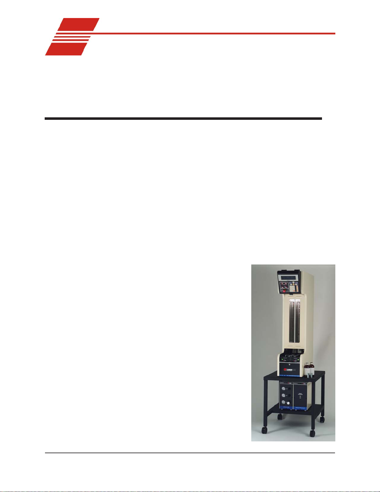
The CANNON® Automatic Viscometer (CAV 2000 Series)
The CANNON® Automatic Viscometer (CAV) is a completely automatic
viscometer designed for unattended operation. The operator places
samples in small vials in the sample holders, enters sample identification
information and initiates the testing with software or front panel keypad
commands. Without any further operator involvement, the CAV determines kinematic viscosity , cleans the capillary tube(s) and prepares the
instrument for the next test. All pertinent test data can be saved to a
computer database for future retrieval and reporting.
Manual
This manual is designed to provide the operator with information about:
VISCPRO
®
software installation and operation
Applications
Precision
CAV 2000 Series equipment and operation
Calibration, service and maintenance procedures
For additional information on initial installation and instrument setup,
refer to the Installation & Setup Guide.
Previous CAV models have been used
in laboratories worldwide for over two
decades. CAV instruments can be found
in R&D laboratories, refinery quality
control laboratories, blending plants,
and independent testing laboratories.
The CAV is ideally suited for the
analysis of both transparent and opaque
samples. A variety of materials, such as
used oils, marine fuels, residual fuels,
and crude oils can be tested with ease.
Precision for the kinematic viscosity
determination of the CAV equals or
exceeds that specified in ASTM
Method D 445. This method is required
by the Society of Automotive Engineers
(SAE) Engine Oil Viscosity Classification SAE J300.
The CAV-2200
CANNON
®
Automatic Viscometer Models CAV-2100 and CAV-2200 with VISCPRO® Instruction & Operation Manual
Version 2g — May, 2009; CANNON
2139 High Tech Road • State College, PA 16803 • USA
®
Instrument Company
Page 8

2
Measuring kinematic viscosity
Kinematic viscosity is a measure of the internal resistance to flow of a
fluid under gravity with the pressure head being proportional to the
density of the fluid. For any particular viscometer, the time of flow of a
fixed volume of fluid is directly proportional to its kinematic viscosity .
Units of measure
Methodology
Manual viscometers
Automatic viscometers
An accepted unit of kinematic viscosity is one centimeter squared per
second, which is called one stoke. The centistoke (which is equivalent to
2
1 mm
/s) is the unit of measure most frequently used.
ASTM Methods D 445 and D 446, included with this manual, describe
appropriate test methodologies and instruments for glass capillary
viscometry.
Sections 9-11 of ASTM D 445 provide detailed instructions for using
manual viscometers. ASTM D 446 suggests a minimum flow time of 200
seconds for nearly all the glass capillary viscometers (see tables in ASTM
D 446).
For automatic viscometers, ASTM D 445 Section 6.1.2 states, “Automated apparatus may be used as long as they mimic the physical conditions, operations or processes of the manual apparatus they replace ... The
automated apparatus shall be capable of determining kinematic viscosity
of a certified viscosity reference standard within the limits stated ...”
Thus, automated viscometers can be used with flow times less than 200
seconds, as long as the kinetic energy correction and precision requirements are met.
CAV tube characteristics
NOTE
Safety cautions
CANNON
®
Automatic Viscometer Models CAV-2100 and CAV-2200 with VISCPRO® Instruction & Operation Manual
Each standard viscometer tube has three bulbs, each of which has its own
calibration. The normal flow times for each bulb are 60-400 seconds.
Each tube has a hundredfold measurement range (for example, range
from 2-200 cSt or 20-2000 cSt for each tube).
CANNON® Instrument Company has not recommended the use of
longer flow times with the CAV, as shorter flow times allow greater
productivity. With longer flow times, the data throughput would be
significantly reduced. However, the viscometer and software design does
permit longer efflux times (up to 600 seconds) as desired by the user.
Please observe the following safety procedures and notices for proper
operation of the CAV:
Make sure that your unit is operated only by qualified personnel.
Version 2g — May, 2009; CANNON
2139 High Tech Road • State College, PA 16803 • USA
®
Instrument Company
Page 9
Make sure that you read and understand all operating instructions
and safety precautions listed in this manual before installing or
operating your unit. If you have questions regarding instrument
operation or documentation, contact CANNON
®
Instrument Company.
Do not deviate from the installation, operation or maintenance
procedures described in this manual. Improper use of the CAV
instrument may result in a hazardous situation and may void the
manufacturer’s warranty.
Handle and transport the unit with care. Sudden jolts or impacts may
cause damage to components.
Observe all warning labels.
Never remove warning labels.
Never operate damaged or leaking equipment.
Never operate the unit without appropriate levels of approved bath
fluid in the bath.
(CAV-2200 only) Do not fill the expansion vessel higher than the
cold fill level.
Unless procedures specify otherwise, always turn off the unit and
disconnect the mains cable from the power source before performing
service or maintenance procedures, or before moving the unit.
Always empty the bath and disconnect cable and tubing connections
to the Service Unit and Solvent Dispensing System before moving
the unit.
Never operate the equipment with damaged mains power cables.
Refer all service and repairs to qualified personnel.
3
General Caution
Hot Surface Caution
Protective Conductor
WARNING
In addition to the cautionary statements listed previously , additional
cautions may be posted throughout this manual. These cautions, identified by the caution symbol (see left) indicate important operational
procedures. Read and follow these important instructions. Failure to
observe these instructions may void warranties, compromise operator
safety , and/or result in damage to the CAV unit.
Hot surface cautions may be attached on or near hot surfaces of the CAV.
A void touching hot surfaces, particularly when operating the CAV at bath
temperatures exceeding 50°C.
The Protective Conductor Terminal symbol is used to indicate required
ground connections for your instrument electrical supply .
When supplying power to this instrument, ensure that the protective
ground (earth) terminals of the instrument are connected to the protective
conductor of the (supplied) line (MAINS) power cord. Use only the
manufacturer-supplied power cord, which should be inserted in a socket
outlet (receptacle) which is also provided with a protective ground (earth)
contact.
Do not use an extension cord (power cable) without a protective
conductor (grounding).
CANNON
®
Automatic Viscometer Models CAV-2100 and CAV-2200 with VISCPRO® Instruction & Operation Manual
Version 2g — May, 2009; CANNON
2139 High Tech Road • State College, PA 16803 • USA
®
Instrument Company
Page 10

4
MAINS
~
AC Power Input Symbol
( O )
Supply OFF Symbol
Hazardous materials
Specifications
lacirtcelE&#traP W0561,zH06/05,CAstlov511:70A-5279#ledoM0022-VAC;W0561,zH06/05,CAstlov511:50A-5279#ledoM0012-VAC
snoisnemiD )"94x53x21(hgihmm5421xpeedmm727xediwmm503
thgieW sredlohelpmasdnadiulfhtabtuohtiw)sbl212(gk69:0002-VACsredlohelpmasdnadiulfhtabtuohtiw)sbl002(gk19:0002-VAC
snoitidnoCgnitarepO 2eergednoitulloP,IIyrogetaCnoitallatsnI,gnisnednoc-nonHR%09-%01,C°03-°51
gnitaResuF "4/1x4/1-1,A51V052M:70A-5279#ledoM0022-VAC;"4/1x4/1-1,A51V052M:50A-5279#ledoM0012-VAC
ecnailpmoC ).ces06,CDV0091(TOP-IH;)CEE/32/37(evitceridegatlovwoL;)CEE/633/98(evitceridCME:kraMEC
12-VAC
The ~MAINS symbol indicates instructions or connections for the AC
power supply . The AC Power input must match the electrical specifications listed on the label on the rear panel of the instrument. The supplied
AC Mains power cord must be attached to the connector labelled
~MAINS. This connection serves as a means of disconnect and should be
readily accessible.
The (O) symbol indicates the OFF position for the electrical switches for
your unit (AC Mains or accessories).
Routine CAV operation may require the use and handling of hazardous
chemicals and solutions. CANNON® Instrument Company strongly
urges the operators and technicians working with the CAV to take proper
safety precautions when working with these materials. These safety
procedures can be found in the Material Safety Data Sheets which
accompany the solutions.
ecnailpmoC/snoitacificepStinUhtaBseireS0002VAC
W0571,zH06/05,CAstlov032:21A-5279#ledoMF0022-VAC;W0571,zH06/05,CAstlov032:01A-5279#ledoMF00
W0571,zH06/05,CAstlov001:71A-5279#ledoM0022-VAC;W0571,zH06/05,CAstlov001:51A-5279#ledoM0012-VAC
"4/1x4
/1-1,A8V052M:21A-5279#ledoMF0022-VAC;"4/1x4/1-1,A7V052M:01A-5279#ledoMF0012-VAC
A-5279#ledoM0022-VAC;"4/1x4/1-1,A51V052M:51A-5279#ledoM0012-VAC
"4/1x4/1-1,A51V052M:71
lacirtcelE&#traP W003,zH06,CAstlov511:7605.16P#traP002-USC
snoisnemiD )"41x02x7(hgihmm653xpeedmm805xediwmm871
thgieW )sbl72(gk3.21
snoitidnoCgnitarepO 2eergednoitulloP,IIyrogetaCnoitallatsnI,gnisnednoc-nonHR%09-%01,C°03-°51
gnitaResuF "4/1x4/1-1,A4V052M:sledoMllA
ecnailpmoC ).ces06,CDV0091(TOP-IH;)CEE/32/37(evitceridegatlovwoL;)CEE/633/98(evitceridCME:kraMEC
#traP 8605.16P#traP001-UDStnevloS-elgniS
snoisnemiD )"41x02x7(hgihmm653xpeedmm805xediwmm871
thgieW )sbl52(gk4.11
noitarepO citamuenP
CANNON
®
Automatic Viscometer Models CAV-2100 and CAV-2200 with VISCPRO® Instruction & Operation Manual
W006,zH05,CAstlov032:8015.16P#traP002-USC
.tinuruoyhtiwdeilppusdrocrewopdevorppaehtylnoesU
6705.16P#traP001-UDStnevloS-lauD
Version 2g — May, 2009; CANNON
2139 High Tech Road • State College, PA 16803 • USA
®
Instrument Company
ecnailpmoC/snoitacificepStinUecivreSseireS0002VAC
snoitacificepStinUgnisnepsiDtnevloSseireS0002VAC
Page 11

5
VISCPRO® for Windows
®
VISCPRO® is a powerful software product designed to provide a generic
instrument interface for controlling and operating your CANNON
instrument(s) via computer. When the Remote mode setting is selected
with the instrument keypad, all instrument functions necessary for testing
may be computer-controlled. VISCPRO
modules for processing and displaying sample data.
Installing VISCPRO® software
T o install the VISCPRO® software, follow the instructions below in the
sequence presented. Make certain that you complete the sections on
checking instrument settings and initial calibration data. If you encounter
difficulties at any stage in the installation process, call CANNON
service at 814-353-8000.
Computer requirements
Consult CANNON® Instrument Company at 814-353-8000 for current
computer specifications. The computer should be a PC with a working
version of the Windows® operating system (XP® or above) installed.
®
®
also includes reporting/analysis
®
Windows® XP
®
installation
Installation actions
1. Turn on your computer. Wait for the Windows® software to load.
2. Insert the first VISCPRO
®
installation disk or CD-ROM into the disk
drive. If the installation program does not begin automatically, click
Settings/Control Panel from the Windows® Start Bar. Then double-
click the Add/Remove Programs icon and follow the W indows
prompts to complete the installation procedure. The executable file
for VISCPRO® software installation is SETUP.EXE.
The installation program will:
create a directory for your program files. The default directory is
C:\Program Files\Cannon Instrument\VISCPRO).
write SETUP information to the Windows
®
registry.
copy the software executable file and other necessary files to the
directory you specify.
update other files in your Windows
compatible with the current VISCPRO® software.
place a shortcut icon for the VISCPRO
Windows
®
desktop.
®
directories to versions fully
®
executable file on your
Configuration diskette (First-time installation only!)
If you received a Configuration floppy diskette with your VISCPRO II
software, follow the instructions that came with the diskette to copy the
SAMPLES.MDB file to your VISCPRO II installation directory.
CANNON
®
Automatic Viscometer Models CAV-2100 and CAV-2200 with VISCPRO® Instruction & Operation Manual
Version 2g — May, 2009; CANNON
2139 High Tech Road • State College, PA 16803 • USA
®
Instrument Company
Page 12
6
Running the software
the VISCPRO II icon
Title Bar
Menu Bar
Provide power to the CAV instrument, and verify serial connections to
the computer. To load your newly-installed VISCPRO® software, doubleclick on the VISCPRO
®
icon on your Windows® desktop (Windows
®
NT® users can click St art/All Programs/VISCPRO/VISCPRO 2.0).
If this is an initial installation, and you received a configuration disk with
your installation software package, make certain that the samples.mdb
file has been copied to the sample installation directory (see separate
instruction sheet for sample database location on your computer hard
drive). Your software may have already been preconfigured with instrument settings unique to your instrument, including instrument type(s),
tube ranges and serial #s, and calibration constants. In a moment, we will
verify these settings. Right now , your computer monitor should look
something like this.
Sample
Input
window
Analysis
window
Status bar
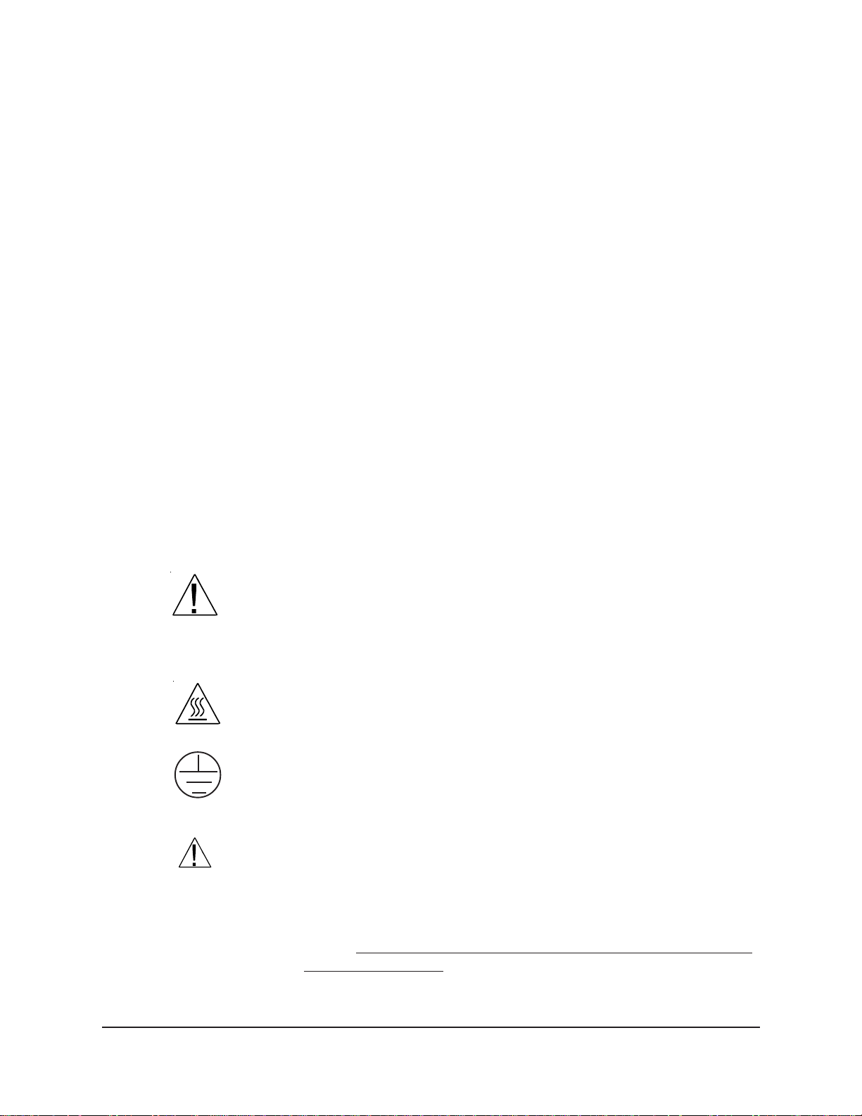
The VISCPRO® primary display
CANNON
The VISCPRO® primary display window is framed on the top by the
VISCPRO® title bar and menu bar, and on the bottom by the VISCPRO
status bar. The application window may have been preconfigured to include
two child windows which can be opened and closed independently. The first
®
Automatic Viscometer Models CAV-2100 and CAV-2200 with VISCPRO® Instruction & Operation Manual
Version 2g — May, 2009; CANNON
2139 High Tech Road • State College, PA 16803 • USA
®
Instrument Company
®
Page 13
is a Sample Input window that describes your CANNON® instrument and
provides controls for running tests. The second is an Analysis window
that presents data from CAV tests.
7
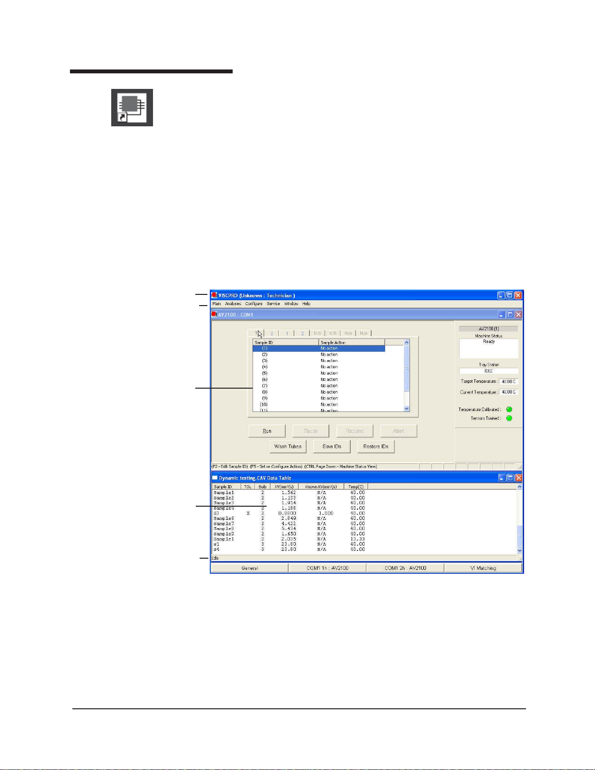
The Sample Input window (note networked instrument tubes on tube tabs)
NOTE
If the Sample Input window does not appear when the software loads, click
View Instrument from the Main menu, then click the desired instrument
group (type of instrument, e.g. CAV, CCS, PolyVISC) from the list of
available instruments and click OK. If the Available Instruments list box is
blank, your CAV instrument may not be on-line. Check cable connections
and make certain the control panel red power switch is ON. (Turn the
switch clockwise for ON. Push the switch in when turning the unit OFF.)
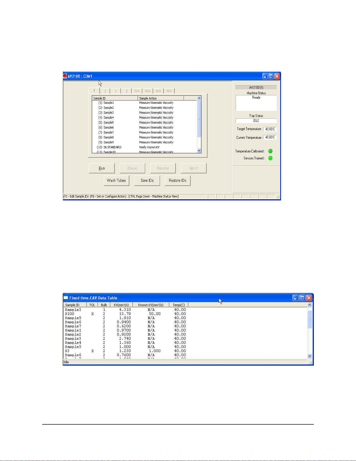
The Sample Analysis Table window displays report data based on user-configurable
parameters.
CANNON
®
Automatic Viscometer Models CAV-2100 and CAV-2200 with VISCPRO® Instruction & Operation Manual
Version 2g — May, 2009; CANNON
2139 High Tech Road • State College, PA 16803 • USA
®
Instrument Company
Page 14
8
Checking configuration
Configuration disk
For first-time installations, check your software packet for a CONFIGU-
®
RATION floppy disk after installing VISCPRO
. If you have one, insert
the disk in your floppy disk drive and follow the instructions printed on
the disk label to add factory calibration information for your instrument
to your VISCPRO
®
database.
CAUTION
Configuration protection
Logging in
Copying floppy disk information to your VISCPRO® directory will overwrite existing sample data. If you wish to restore the original configuration, make certain to archive your sample data before doing so (see
Chapter 13 for information on using the Database Manager software).
Follow the procedures in the next several sections of this chapter to
verify/edit the instrument and calibration settings to ensure that they
conform to the actual characteristics of your CANNON® instrument.
T o check the configuration settings for your instrument(s), you must log
in to the security system as a manager. The software is installed with a
default Manager account. This account has no password, allowing any
operator access to manager-level software functions as long as the
password is not activated/changed. If you would like to engage the fullrelease security options, see Security Options in Chapter 4 for instructions.
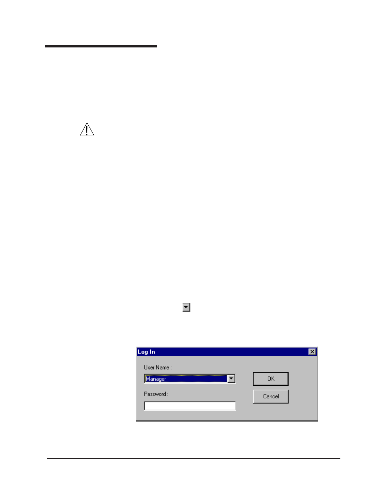
1. Use your mouse to click Main from the VISCPRO® menu bar.
2. Click Log In from the Main menu options.
3. Click on the (arrow) on the right side of the User Name: list box
to display the list of registered users.
CANNON
4. Click Manager. Do NOT enter a password!
5. Click OK. The Log In window will close automatically and you will
be logged in as management personnel.
®
Automatic Viscometer Models CAV-2100 and CAV-2200 with VISCPRO® Instruction & Operation Manual
Version 2g — May, 2009; CANNON
2139 High Tech Road • State College, PA 16803 • USA
®
Instrument Company
Page 15
Checking Instrument Settings
1. Use your mouse to click (select) Configure from the VISCPRO
menu bar.
2. Select your instrument from the list of available instruments (there
may be only one instrument in the list).
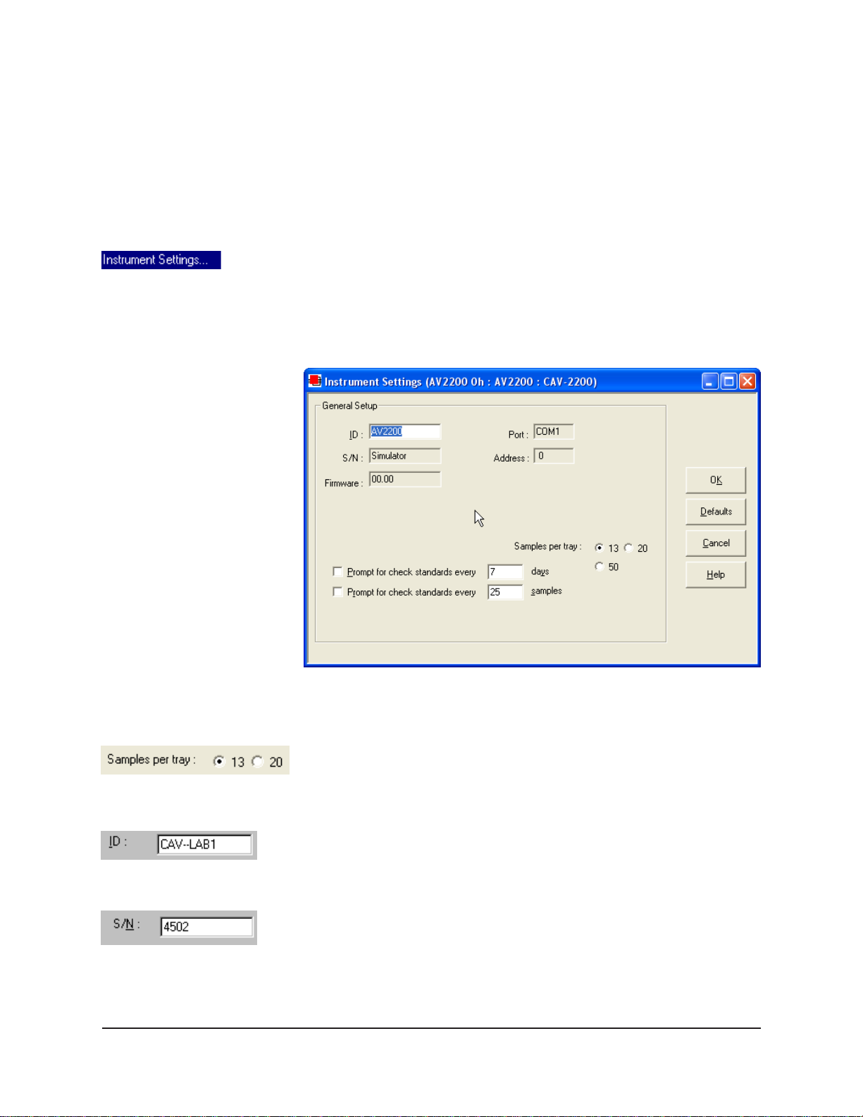
3. Select Instrument Settings from the list of configuration options.
The Instrument Settings window will appear.
You will use the Instrument Settings window (see below) to describe
and control CAV instrument operational features. These settings affect
the instrument as a whole. Check the instrument settings for your instrument per the instructions below , and make any necessary changes:
9
®
CANNON
The Instrument Settings window
Click the radio button corresponding to the number of sample positions
for your sample trays.
Use the ID field to input instrument identification information using up to
16 alphanumeric characters.
The S/N: field (non-editable) indicates the four-digit serial number from
the label on the CAV rear service panel.
®
Automatic Viscometer Models CAV-2100 and CAV-2200 with VISCPRO® Instruction & Operation Manual
Version 2g — May, 2009; CANNON
2139 High Tech Road • State College, PA 16803 • USA
®
Instrument Company
Page 16
10
Prompt options
Viewing/editing setup information
The Prompt for Check Standards options permit you to set a computer -
ized “alarm clock” which will pop up a message reminder to run a
calibration standard (using the Verify Known KV viscosity action) based
on the schedule you set with the control. Notice that you can specify a
reminder after “x” number of days and/or “x” number of samples. Click
the check box(es) to enable/disable each reminder.
When you have verified all settings, click OK.
If your instrument has already been set up by a technician, you can use
the instructions in this section of the manual to check or, if necessary,
change the instrument settings.
1. Click Configure from the VISCPRO
®
menu bar .
2. Select your instrument gropu and instrument from the list of avail-
able instruments.
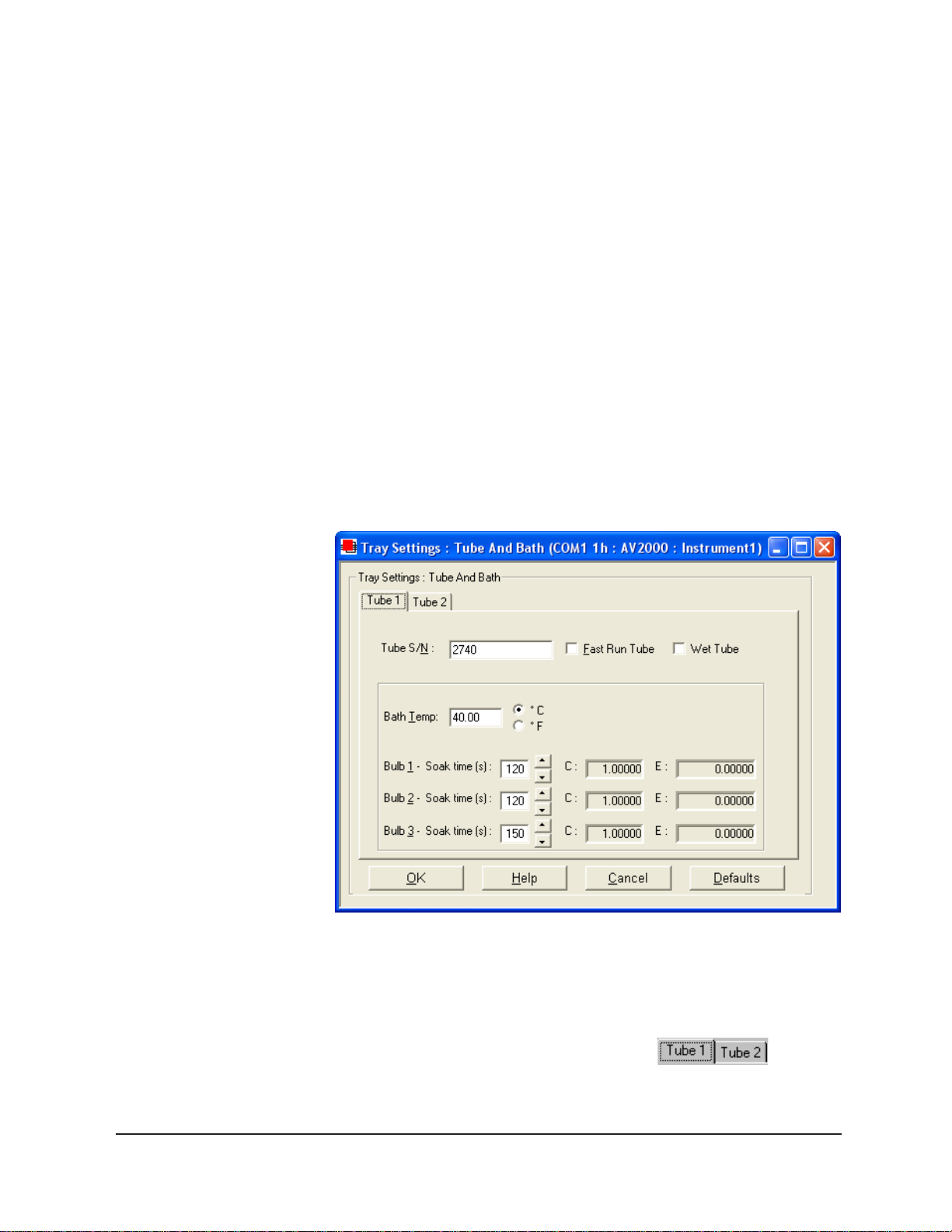
3. Select Tray Settings: Tube and Bath from the list of configuration
options. The Tray Settings: Tube and Bath window will appear.
CANNON
The Tray Settings: Tube and Bath window
The Tray Settings: Tube and Bath window contains setup information
for each tube associated with your instrument. You can click on the tube
tabs to see the setup information for each tube:
4. Click on the tube tab for Tube 1 (the tube on the left).
®
Automatic Viscometer Models CAV-2100 and CAV-2200 with VISCPRO® Instruction & Operation Manual
Version 2g — May, 2009; CANNON
2139 High Tech Road • State College, PA 16803 • USA
®
Instrument Company
Page 17
5. Verify that the tube serial number (Tube S/N) is correct. If it is not,
input the correct serial number in the text box.
Each tube should have
a unique serial number!
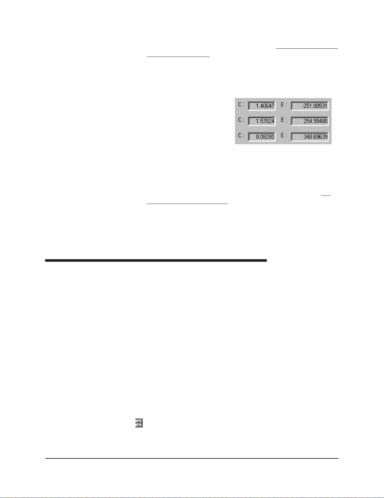
6. Verify that the calibration values (C and E) for each bulb are avail-
able. If calibration data is not available, the default values are C=1
and E=0.
11
NOTE
For first-time installation, make
certain that the factory-prepared
Configuration file has been
copied to the VISCPRO II
directory per instructions.
7. Compare calibration values
to any existing archives of
Sample calibration data
the calibration constants for
each bulb of Tube 1. The values, which cannot be edited from the
Tray Settings: Tube and Bath window , should be identical.
8. Write down the tube and bulb number for any incorrect values.
will change these values later, using the Tube Settings: Calibration
window.
9. Click on the tube tab for Tube 2 and repeat steps 7-8 above. When
you are done, click OK to close the Tray Settings: Tube and Bath
window.
Manually changing tube calibration constants
If you discovered any errors in the values of the calibration constants (see
previous section), follow the directions in this section to manually correct
them using calibration information previously obtained for your unit. If
the calibration values are correct, instrument setup is complete.
We
CANNON
NOTE
This procedure for manually entering/changing calibration constants
bypasses the normal calibration procedure. To ensure the most accurate
viscosity readings, CANNON® Instrument Company recommends that the
instrument be calibrated per the calibration procedure outlined in Chapter
3.
1. Click Configure from the VISCPRO® menu bar .
2. Select your instrument from the list of available instruments.
3. Select Calibration from the list of configuration options. The
Calibration window will appear (see next page).
The Calibration window provides controls for calibrating each tube
associated with your instrument. You can click on the tube spin controls
to display current tube constants and valid check standard data
available for calibration of each tube.
®
Automatic Viscometer Models CAV-2100 and CAV-2200 with VISCPRO® Instruction & Operation Manual
Version 2g — May, 2009; CANNON
2139 High Tech Road • State College, PA 16803 • USA
®
Instrument Company
Page 18
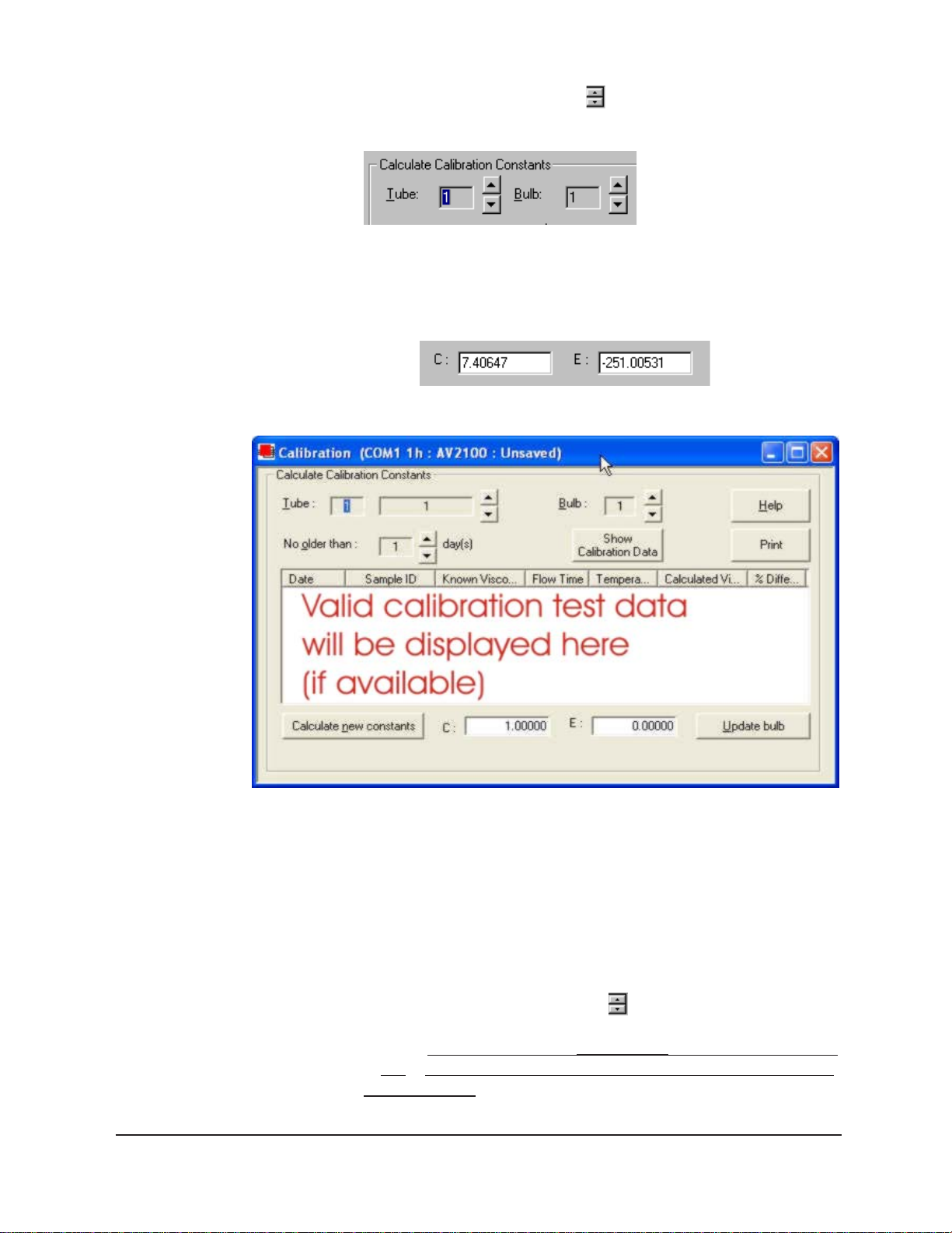
12
Procedure
1. Make sure that the spin controls for Tube and Bulb are both set
to “1”:
This corresponds to the left-hand tube in the left-hand bath and the
bottom bulb in the tube.
2. Check the values for the calibration constant(s) as they appear at the
bottom of the window:
CANNON
The Calibration window
Compare these values to your archive of the calibration constants (if
available) for tube 1 and bulb 1. The values should be identical.
3. If they are not, place your cursor in the appropriate field, delete the
entry, then type the correct values for the constants in the text boxes.
4. Click Update bulb.
5. Use the tube and bulb spin controls
to select the tubes/bulbs for
which you noted calibration constant errors. Input the correct values
for each.
Make certain to click Update bulb after you have corrected
C and E calibration values for each bulb BEFORE selecting the next
tube and/or bulb.
®
Automatic Viscometer Models CAV-2100 and CAV-2200 with VISCPRO® Instruction & Operation Manual
Version 2g — May, 2009; CANNON
2139 High Tech Road • State College, PA 16803 • USA
®
Instrument Company
Page 19

6. When you have entered corrected constant values for each bulb on
both tubes, click
You have verified the software configuration of VISCPRO
to exit the Calibration window.
®
. T o test
samples with your instrument, follow the instructions in Chapter 2. For
additional details regarding operating procedures for your instrument or
software, consult the appropriate section of this manual.
13
CANNON
®
Automatic Viscometer Models CAV-2100 and CAV-2200 with VISCPRO® Instruction & Operation Manual
Version 2g — May, 2009; CANNON
2139 High Tech Road • State College, PA 16803 • USA
®
Instrument Company
Page 20

14
This page intentionally left blank.
CANNON
®
Automatic Viscometer Models CAV-2100 and CAV-2200 with VISCPRO® Instruction & Operation Manual
Version 2g — May, 2009; CANNON
®
Instrument Company
2139 High Tech Road • State College, PA 16803 • USA
Page 21

CHAPTER
15
2
CANNON AUTOMATIC VISCOMETER
Preparing the CAV
Turning on the CAV
NOTE
TESTING SAMPLES WITH THE
This chapter of the manual will provide information on testing samples
using the CAV -2100 or CAV-2200 instruments. Observe the safety
cautions noted in the introductory chapter when operating equipment.
The CAV should only be operated by qualified personnel.
1. If CAV power is off, turn on the CAV Bath Unit by rotating the red
power switch on the control panel clockwise. Provide power to the
CSU Service Unit (rear panel On/Off switch) and the Solvent Dispensing Unit (front panel On/Off switch).
If it is necessary to
cut power to the CAV
Bath Unit, press the
power switch IN.
Preparing sample trays
Electrical connections
Using a temperature probe
Sample trays will
slide into place along
the grooved track in
the sample table.
Plated steel vial
adaptors should be
placed in the circular
recesses in the tray .
Glass sample vials slide into the adaptors. To position the first sample
vial under the viscometer tube in preparation for testing, slide the tray
forward until the detente mechanism engages. A heated sample tray
should snap into position against the detent mechanism when the front of
the tray extends approximately 2 centimeters (3/4”) over the edge of the
sample table. The forward edge of an unheated tray will be indented
approximately 2.2 centimeters (7/8”). During sample testing, trays are
automatically advanced by the pneumatic system.
For heated sample trays, verify that the attached three-pin tray cable is
connected to the interior wall connector above the sample table.
A recessed thermometer well at the front of the sample tray permits
insertion of a temperature probe to monitor tray temperature.
CAV-2000 heated sample trays
CANNON
®
Automatic Viscometer Models CAV-2100 and CAV-2200 with VISCPRO® Instruction & Operation Manual
Version 2g — May, 2009; CANNON
2139 High Tech Road • State College, PA 16803 • USA
®
Instrument Company
Page 22
16
Tray/drain heat operations
CAUTION
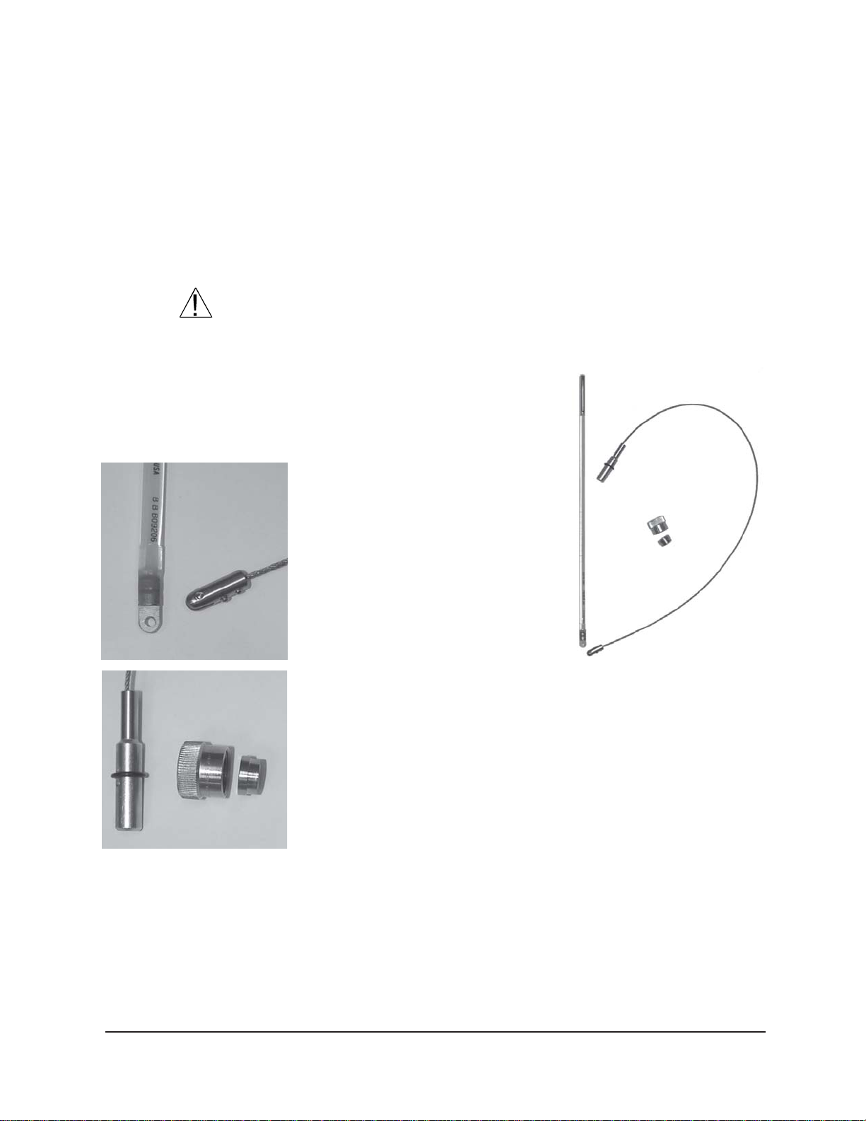
Inserting/removing the CAV reference thermometer
Inserting the thermometer
Thermometer
Cable
Connector
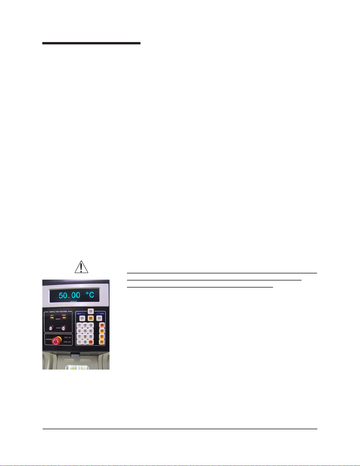
T o provide power to the heated sample trays and/or heated drain lines
which may be installed on your CAV unit, use the heater ON/OFF
switches on the left side of the front panel. These two switches provide
power to left- and right-hand heating elements. To adjust temperature,
use the Adjust knobs on the upper front panel of the Bath Unit. T urn the
knobs clockwise to increase temperature and counterclockwise to lower
it. The knobs regulate the duty cycle of the heaters for the sample trays
and the drain lines. The low-temperature sample heaters will maintain
temperature stability as high as 80°C. The high-temperature sample
heaters will maintain temperature stability as high as 100°C.
Avoid skin contact with heated sample trays, as burns may result. Use
appropriate protection when handling heated samples, vial adaptors, and
sample trays.
ASTM thermometers with speciallyfitting adaptors for the CAV instrument
(see photos) are available from CAN-
NON® Instrument Company . Digital
therometers meeting the ASTM D 445
specifcation are also available.
1. T o install the reference thermometer,
check the current temperature of the
CAV bath and select the calibrated
thermometer appropriate for that
temperature.
Cap
Ferrule
Plug
For additional information
and details for CAV
thermometer installation/
removal, see Appendix A.
Removing the thermometer
CANNON
®
Automatic Viscometer Models CAV-2100 and CAV-2200 with VISCPRO® Instruction & Operation Manual
2. Using the two opposing 0.05” Allen
screws, secure the thermometer
adaptor plate to the connector on the thermometer cable.
3. Using a ladder to access the top of the CAV Bath Unit, remove the
knurled cap, ferrule and O-ring from the thermometer holder.
4. Insert the thermometer assembly into the holder until the plug with
O-ring is seated inside the top of the holder. Rotate the plug until the
thermometer scale is easily visible from the Bath Unit front window .
5. Slide the ferrule over the end of the plug until it seats against the O-
ring.
6. Place the knurled cap over the plug and rotate the cap clockwise to
secure the cap to the top of the thermometer holder. Tighten finger
tight to seal the connection.
T o remove the reference thermometer, permit the bath to cool below
80°C and reverse the above procedure. Use appropriate safety procedures
when handling the thermometer assembly , as it contains mercury.
Version 2g — May, 2009; CANNON
2139 High Tech Road • State College, PA 16803 • USA
®
Instrument Company
Page 23
Local mode operation
The Local mode option permits manual control of CAV functions via the
control keypad on upper front panel of the Bath Unit. Local mode offers
the advantage of convenient and quick testing for an individual sample.
The single-sample drop time or kinematic viscosity is displayed on the
vacuum fluorescent display (VFD).
17
NOTE
Selecting Local mode
NOTES
Setting temperature
WARNING
The VFD is equipped with a screen saver feature which will reduce the
intensity of the display if the keyboard is not touched for five minutes. To
restore the original intensity of the display, press any key on the keypad.
T o select Local mode operation, toggle the Remote/Local (RMT/LOC)
button on the keypad on the Bath Unit to select Local mode operation.
When the unit is in Remote mode, the front panel display will indicate
REMOTE operation. If the display does not indicate REMOTE operation, then the instrument is in Local mode.
Local mode may be selected at any time during CAV operation. Remote
operations will be suspended. When switching from Remote to Local
mode, it is the user’s responsibility to monitor the instrument tube
state(s) and to properly prepare the instrument before running tests.
Operator intervention is required to test each sample in Local mode.
Additionally, test data is not saved to the VISCPRO® database and
viscosity calculations must be performed manually.
Prior to setting the bath temperature, ensure that the reference thermometer in the bath is suitable for the desired temperature range. If not,
remove thermometer from the bath (see previous page). If the bath
temperature rises above the range of the thermometer, it may be damaged. Mercury thermometers pose particular problems, since mercury
from a damaged thermometer may circulate with bath fluid.
CANNON
T o set the temperature in Local mode, press the Set Temp key on the
front panel keypad, select the desired bath (CAV-2200 only) and input the
target (desired) temperature(s) using the keypad characters. Then press
the Enter key. Acceptable values are any numbers between 20°C and
100°C (150°C for high-temperature CAV models). If necessary, you may
use the decimal point key to input temperature to the nearest 0.01°C.
NOTE
To cancel temperature selection before completing the procedure, press
the Set Temp key a second time.
After the target temperature has been set, the CAV bath temperature will
be adjusted to the target temperature and the bath will equilibrate at the
test temperature. When the instrument has attained a temperature within
®
Automatic Viscometer Models CAV-2100 and CAV-2200 with VISCPRO® Instruction & Operation Manual
Version 2g — May, 2009; CANNON
2139 High Tech Road • State College, PA 16803 • USA
®
Instrument Company
Page 24

18
0.05°C of the target temperature, the current bath temperature will be
displayed in large type (CAV-2100 only) on the display.
Preparing the bath
When operating in Local mode, visually check the condition of the
viscometer tubes prior to initiating a sample run. If sample or solvent
residue remains in the tube, use the Local mode options to wash and/or
dry the tubes (see Chapter 5, Solvent wash by operator (Local mode)).
Testing samples
1. Pour the test sample into a glass vial and slide the vial into the steel
vial adaptor in the sample tray .
NOTE
Do not fill the vials to the top. Sample overflow may damage the seals of
the LOAD cylinder.
2. Position the vial directly underneath the viscometer tube, using the
detente mechanism as a guide in orienting the sample. A heated
sample tray should snap into position against the detent mechanism
when the front of the tray extends approximately 2 centimeters (3/4”)
over the edge of the sample table. The forward edge of an unheated
tray will be indented approximately 2.2 centimeters (7/8”).
3. Press the Test button.
4. Select the desired tube for testing (Left (1) or Right (2)).
5. Select the desired protocol for the sample drop:
Run (Determine Bulb) will calculate the optimal test bulb.
Run (Use Previous Bulb) will test the sample using the same bulb
as the previous test (this option is desirable when averaging multiple
drop times for the same sample).
The sample will be tested and the drop time and/or kinematic viscosity (see next page) will be indicated on the VFD.
6. After the test has been completed, you may rerun the sample using
the above procedure, or wash the tube using the keypad WASH
option (see pages 18-19 for details on keypad options).
Aborting a test
NOTE
CANNON
®
Automatic Viscometer Models CAV-2100 and CAV-2200 with VISCPRO® Instruction & Operation Manual
T o immediately halt testing for a given tube/tray (left/right), press the
Stop Left and/or Stop Right button on the keypad. On rare occasions
when it is necessary to quickly abort tests on both tubes and remove
power from the unit, press the red power button on the control panel.
Aborting a test using either method clears all sample test information for
that tray. If test actions are aborted, it is the responsibility of the user to
restore the instrument to a safe state before running tests (see Local
mode diagnostics/maintenance in chapter 5 for more information).
Version 2g — May, 2009; CANNON
2139 High Tech Road • State College, PA 16803 • USA
®
Instrument Company
Page 25

Concluding a test
19
At the conclusion of a test, the drop time for the sample will be displayed
on the display screen. Record the drop time and press the Enter key to
return to the temperature display . Then remove the sample from the tray.
CAUTION
Use appropriate procedures when handling heated sample trays and
heated samples to avoid the possibility of burns.
Empty the oil from the sample vials into the appropriate container(s) for
use/disposal and clean glass vials per approved laboratory procedures.
Wipe any excess oil from the table, sample tray and vial holders (glass
vials only) using an absorbent paper towel. If necessary , clean these items
by wiping with a paper towel wetted with appropriate solvent.
Obtaining kinematic viscosity (KV) readings in Local mode
Local/Remote operation of the CAV is selected via the RMT/LOC button
on the CAV keypad. Local mode operation involves CAV control via the
keypad. Remote operation involves CAV control via the VISCPRO
software interface. Pressing the RMT/LOC button on the CAV keypad
will toggle between the Remote and Local operation modes. To obtain
kinematic viscosity readings in local mode with the CAV 2000 Series
instrument, calibrate each bulb for each bath at the desired bath temperature using VISCPRO II with the instrument set in REMOTE mode.
After calibration, open the Tray Settings: Tube and Bath window for
the desired instrument. Make sure the settings are correct and close the
window by clicking the OK button. This action will transmit the bath
temperature(s), the soak times, and the current bulb calibration constants
to the instrument.
Press the RMT/LOC button on the CAV keypad to change the instrument
mode to LOCAL. Then press the Menu button on the CAV instrument.
On the screen, select option #7: Display KV : YES/NO. Toggle the #7
button to select the desired option. If YES is selected, the KV will be
displayed at the end of a test.
NOTE
If the instrument is set to display KV, it will only display KV if the tube
calibration constants have been loaded as described above; otherwise, it
will display the efflux time. If multiple drops are required for a result, the
customer will need to average the KVs resulting from each drop.
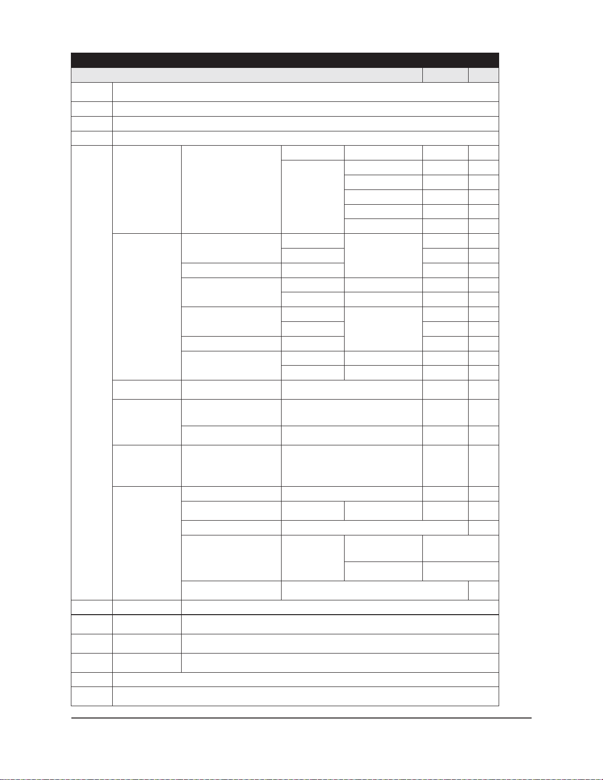
Other Local mode keypad options
The Local mode keypad options described above are the more common
functions available. The Keypad Options table (see next pages) contains
a list of all Local mode keypad options, including entry parameters and
(where applicable) default instrument settings.
Any incomplete keypad command sequence may be cancelled by
pressing the keypad button that initiated the sequence.
Version 2g — May, 2009; CANNON
2139 High Tech Road • State College, PA 16803 • USA
CANNON
NOTES
®
Automatic Viscometer Models CAV-2100 and CAV-2200 with VISCPRO® Instruction & Operation Manual
®
Instrument Company
Page 26

20
Acceptable keypad input is indicated audibly with a short beep. Unacceptable keypad input is indicated audibly with a longer tone.
Remote operation (computer-controlled)
Local/Remote operation of the CAV is selected via the RMT/LOC button
on the control panel. Pressing the button will toggle between the Remote
and Local operation modes. The Remote mode option permits automatic
control of CAV functions via the VISCPRO
Remote mode offers the advantage of multi-drop, multi-sample automatic
testing for up to 100 samples depending on tray type. Sample data is
automatically stored to the VISCPRO® database for future reporting/data
collection. Additionally, several reports (analyses) may be used to
calculate and display kinematic viscosity and viscosity index (VI) values.
See the chapters on VISCPRO
All analyses provide a dynamic operation mode which can immediately
display and transmit test results to your computer screen, printer, and/or
serial port for in-house data collection. See Chapter 6 for more information on configuring analyses.
T o select Remote mode operation, press the Remote/Local (RMT/LOC)
button on the keypad on the Bath Unit until the front panel vacuum
fluorescent display indicates REMOTE operation. If the display does not
indicate REMOTE operation, then the instrument is in Local mode.
®
controlling software.
®
analyses for further information.
NOTE
Setting temperature
NOTE
NOTE
Remote mode may only be selected when the CAV is idle.
T o set the temperature in Remote mode, load the VISCPRO® software
and click Configuration. Select the CAV from the list of available
instruments and click Tray Settings: Tube and Bath. Select the desired
tube and type the desired temperature in the Bath Temp: field. Accept-
able values are any numbers between 20°C and 100°C (150°C for CAV
high-temperature models). If necessary, you may use the decimal point
key to input temperature to the nearest 0.01°C. Press OK to save the
temperature setting.
To cancel temperature selection before completing the procedure, click
Cancel.
After the target temperature has been set, the CAV bath temperature will
be adjusted to the target temperature and the bath will equilibrate at the
test temperature. When the instrument has attained a temperature within
0.05°C of the target temperature, the current bath temperature will be
displayed in large type on the display for CAV-2100 models.
Placing the instrument in Remote mode while the VISCPRO software is
loaded will reset the bath temperature(s) to match the VISCPRO settings.
CANNON
®
Automatic Viscometer Models CAV-2100 and CAV-2200 with VISCPRO® Instruction & Operation Manual
Version 2g — May, 2009; CANNON
2139 High Tech Road • State College, PA 16803 • USA
®
Instrument Company
Page 27
COL/TMR
TFELPOTS.ebuttfelrofytivitcaspotS
THGIRPOTS.ebutthgirrofy
PMETTES .retnEsserpnehT.erutarepmetderisedtupnidna)ylno0022-VAC(htabtceleS
UNEMsretemaraPtse
)5
TSET
HSAW
YRD
RETNE .seulavtupnitpeccaotyrtneatadfonoitelpm
,5,4,3,2,1,0
.,9,8,7,6
.edometomeR
tivitcaspotS
T)1ebuttfelesu)1
sretemaraPhsaW)2ebuttfelesu)1
stinUerutarepmeT)3
erutarepmeTetarbilaC)4
srosneSniarT
ecivreS)6
ON
/SEY:VKyalpsiD)7snoitpoON/SEYelggototretnEsserP
ebuttfelesu)1
ebutthgiresu)2
ebuttfelesu)1
ebutthgiresu)2
ebuttfele
su)1
ebutthgiresu)2
sum
F°)1
C°)2
hgiRtsujdA)5
sutat
S)3 scitsongaidtnemurtsnirofsgnittesdnasegatlovsyalpsiD A/N
drowssaP)5
)edoMlacoL(snoitpOdapyeK
noitpircseD/dnammoCdapyeK sretemaraP tluafeD
yalpsiD.edomlacoLotetomeRmorfsegnahC
ebutthgiresu)2
ebutthgiresu)2
.sebutnurtsafrof"0"tateS:3BhsaWA)281-05
lS)4.emitkaostnevlostupnI03-12
eht,ylnotnevloselgnisagnisufI:ETON
."0"ottesebt
meTtnerruCoreZ)2
srosnesllaniarT)3
sserddAtnemurtsnI)1.
lliFebuTlaunaM)4
BsuoiverPesU(nuR)2
ocnopuRETNEsserP.atadciremuntupniotdesU
nopuRETNEsserP.atadciremuntupniotdesU
)BroA(hsaWdesunuehtrofseulav
.sebutnurtsafrof"0"tateS:3BhsaWB)781-02
tesffOerutarepmeTtnerruCteS)1
tesffOerutarep
srosnesebuttfelniarT)1
srosnesebutthgirniarT)2
.stPpirTebuTtfeLtsujdA)4
.stPpirTebuTt
epyTsnoitacinummoC)2
)bluBenimreteD(nuR)1
)blu
.nottub
.snoitpo
.sretemaraphsaWgnisuebutretemocsivsehsaW
.sretemaraphsaWgnisuebutretemocsivseirD
:)s(emiTkaoS]x[bluB552-0021
sretemaraPdecnavdA
)detcirtser(
:1BhsaWA)0
:2BhsaWA)181-09
:)s(lliFvlS)3.emitlliftnevlostupnI03-12
:)s(kaoSv
:1BhsaWB)5
:2BhsaWB)681-05
sulFvlS)8.emithsulftnevlostupnI06-12
:)s(h
:)s(riAlaniF)9.emityrdriatupnI552-5105
.ebutretemocsiveht
584-SR)1
232-SR)2
ebuTtfeLesU)1
ebuTthgiResU)2
xaM)1002-02002
.em
it
.emit
erisedtcelesotsnottubdapyekesUC°/F°C°
utarepmettupniotsnottubdapyekesU
.lecnacotUNEM.tpecca
tinUhtaBhcaerofeulaveuqinutupnI9-00
l
liFlaunaM)1
nwoDpuC)2
.seulavtupnitpeccaotyrtneatadfonoitelpmoc
:)s(emiTlliF1bluB
:)s(emiTtceleS1bluBniM)202-5.35.01
emiTlliF2bluBniM)34-00.1
:)s(emiTytpmEbluBxaM)4006-09004
iTytpmEebuTxaM)5521-551
:)s(em
hsaw"X"bluB/AtnevlostupnI
hsaw"X"bluB/BtnevlostupnI
.stinud
ecnerefermorfer
RETNEsserpnehT.°10.0tseraenehtotretemomreht
otRETNE.deraelceblliwtesffoerutarepmettnerrucehT
.detelpmocsigniniartnehwELDIetacidni
lliwyalpsiD.erudecorpgniniartrosnescitamotuasetaitinI
rednulaivehtnielpmasgnisutnemtsujdarosnessetaitinI
.epytnoitcennoctupnIA/N232-SR
81-011
81-09
A/NA/N
A/NA/N
A/NA/N
serP
detcirtsersseccaotynapmoCtnemurtsnINONNACmorfdrowssaptupnI
nidilavnieraTHGIR/TFELPOTSdnaCOL/TMRtpecxesnoitarepodapyekllA.edometomeRninehwsetacidni
"1"dloH.pucesiarotsserP
otnidiuqilwardotnwodyek
.niardotyekesaeleR.ebut
.pucrewolots
.niardlliwdiuqiL
A/N
21
CANNON
®
Automatic Viscometer Models CAV-2100 and CAV-2200 with VISCPRO® Instruction & Operation Manual
Version 2g — May, 2009; CANNON
®
Instrument Company
2139 High Tech Road • State College, PA 16803 • USA
Page 28

22
Testing samples
Loading software
NOTES
NOTES
1. Turn on the computer and load the CAV software by double-clicking
the VISCPRO
If the software is already loaded, use your computer mouse to click Main
from the menu bar and click Poll for Instruments from the Main menu
options. This will establish communications between the computer and
the on-line instrument.
Permit the bath(s) to stabilize at test temperature before testing samples.
®
icon on the Desktop.
2. Pour sample material into the glass vial(s). Fill to within 1.3 cm (½”)
of the top of each vial (somewhat less sample may be required for
testing in lower bulbs of the viscometer). Insert the glass vials into
the steel carrier cylinders and place the cylinders into the sample tray .
Do not fill the vials to the top. Sample overflow may damage the seals of
the LOAD cylinder. You should run calibration check standards per your
established laboratory procedures. Recalibrate the CAV (see Chapter 3,
Calibration) if result variance warrants.
3. Place the sample tray into the track underneath the viscometer tube.
Push the sample tray forward until the first vial is under the viscometer tube. A heated sample tray should snap into position against the
detent mechanism when the front of the tray extends approximately 2
centimeters (3/4”) over the edge of the sample table. The forward
edge of an unheated tray will be indented approximately 2.2 centimeters (7/8”).
!
CAUTION
4. Ensure that the splash guard(s) in front of the viscometer tube has
been secured in place with the thumbscrew . If a splash guard has
been removed, replace it.
The splash guard(s) may be removed to allow the user to handle the
sample not yet running (replace with a different sample, etc.). However,
make certain to return the splash guard to its proper position to prevent
sample/solvent contamination and to protect the viscometer tube tip. Do
not allow your hands to contact or obstruct the pneumatic mechanism or
heated sample trays and electrical connections.
5. Check the thermometer in the temperature bath to make sure the bath
is holding the proper temperature. If necessary , calibrate the CAV
temperature control probe using the temperature calibration procedure in Chapter 3.
6. Open the View Instrument Group window (if it is not already open)
by clicking View Instrument from the Main menu and selecting the
desired instrument group from the list box (see Chapter 4 for more
information).
CANNON
®
Automatic Viscometer Models CAV-2100 and CAV-2200 with VISCPRO® Instruction & Operation Manual
Version 2g — May, 2009; CANNON
2139 High Tech Road • State College, PA 16803 • USA
®
Instrument Company
Page 29
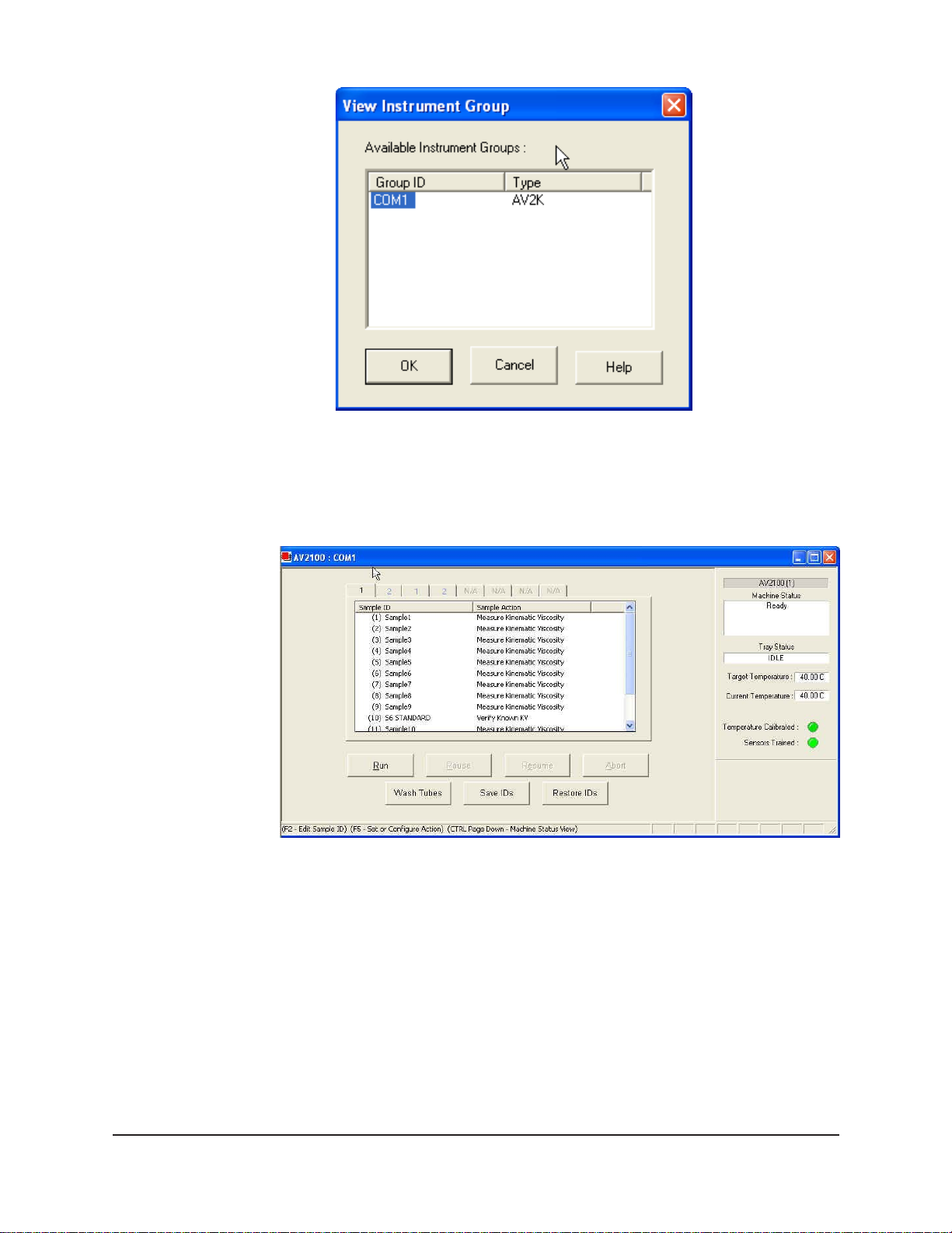
The
View Instrument Group
window
7. Click OK to display the Sample Input View for the desired group:
23
CANNON
The Sample Input window
Then click the Tray tab corresponding with the desired viscometer tube.
8. Double-click on Sample ID (1) with the left mouse button to access
the sample ID data entry field (or press 2).
9. Enter sample ID information in the sample list box using your
computer keyboard. After you have typed the sample ID, press the
T key to save the entry and move the cursor to the next Sample
ID field. Or press R to save the entry .
®
Automatic Viscometer Models CAV-2100 and CAV-2200 with VISCPRO® Instruction & Operation Manual
Version 2g — May, 2009; CANNON
2139 High Tech Road • State College, PA 16803 • USA
®
Instrument Company
Page 30
24
NOTE
NOTE
Running check standards
Once sample information is entered, the software automatically assigns
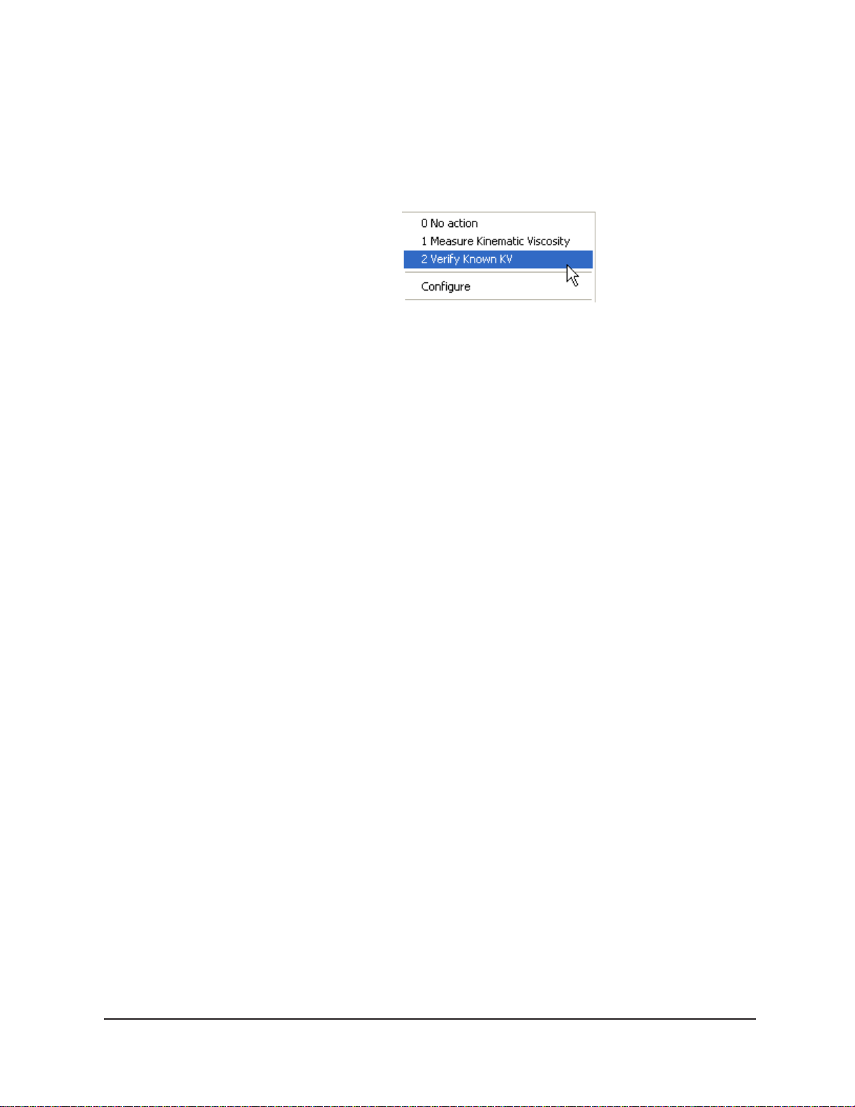
a sample action, Measure Sample Viscosity, for the sample. If you do not
enter a sample ID, the sample is automatically labeled Unknown.
T o select or change a sample action, highlight the appropriate Sample
ID(s) using the mouse or arrow keys, then click the RIGHT mouse
button to access sample action options:
Then you may select the desired action by highlighting it and clicking the left mouse button.
For additional information on software data entry features, including
multiple sample selection and cut & paste options, see Testing
samples—software options in Chapter 4.
If V erify Known KV is selected as the test option for a sample, the
Viscosity Action window will open automatically. Enter the neces-
sary check standard data, including the Check Standard viscosity
from the standard bottle, and click OK to complete data entry . T o
revise or confirm standard data, right-click on the desired sample ID
from the list box and select Configure from the popup menu choices.
NOTE
Pausing a test
NOTE
See Chapter 4 for additional information on the Viscosity Action window.
10. Continue entering sample information for all desired trays. When
sample ID data entry is complete, check the Tray Status window to
verify that all trays are ready for testing.
11. Click on the RUN button at the bottom of the Sample Input win-
dow . The Select T rays window will open.
12. Click on the check box(es) to select the desired prepared tray(s) for
automatic testing. Then click OK to begin the CAV test(s).
T o temporarily halt testing for a given tube/sample, click the Pause
button from the Sample Input window . Then select the desired tray(s)
and pause action(s) from the Select Trays window (Pause Now will
immediately pause test actions; Pause after current sample will pause
testing after the current test is complete). Click OK to pause testing for
the selected tray(s).
If the test was paused prior to the initiation of the Wash cycle, drop time
data for that sample will be discarded.
CANNON
®
Automatic Viscometer Models CAV-2100 and CAV-2200 with VISCPRO® Instruction & Operation Manual
Version 2g — May, 2009; CANNON
2139 High Tech Road • State College, PA 16803 • USA
®
Instrument Company
Page 31

Resuming a test
Aborting a test
25
T o resume test actions for paused trays, click the Resume button from
the Sample Input window. Then select the desired trays from the Select
Trays window. Click OK to resume sample testing (see note above).
T o permanently halt testing for a given tube/tray, click the Abort button
from the Sample Input window. Then select the desired trays from the
Select Trays window. Click OK to abort testing for the selected tray.
NOTE
Concluding a test
CAUTION
Aborting a test clears all sample test information for that tray. If test
actions are aborted, it is the responsibility of the user to restore the
instrument to a safe state before running tests (see Service menu
options in chapter 4 for more information on tube washing and drying).
After automatic testing has been completed for a sample tray , make
certain that the final sample has drained and the calculated viscosity for
each sample tested is displayed in the Sample Input window . The tray
status for the tube, as indicated in the VISCPRO® Instrument View Tray
Status window, will be PAUSED. Click the Resume button to clear
sample data from the Sample Input window and return the instrument to
IDLE status. Then remove the sample tray from the tray rack.
Use appropriate procedures when handling heated sample trays and
heated samples to avoid the possibility of burns.
Empty the oil from the sample vials into the appropriate container(s) for
use/disposal and clean glass vials per approved laboratory procedures.
Wipe any excess oil from the table, sample tray and vial holders (glass
vials only) using an absorbent paper towel. If necessary , clean these items
by wiping with a paper towel wetted with appropriate solvent.
Working with Instrument Groups
VISCPRO II provides a new , convenient interface for working with
multiple CANNON instruments simultaneously . Rather than requiring the
user to open individual Instrument Views for each online instrument, the
Sample Input window (formerly the Instrument View window in
VISCPRO) provides individual tabs for each viscometer tube, making it
easy to enter sample information for up to four different instruments
(eight viscometers). The Machine Status window makes it possible to
monitor the performance of all instruments in an Instrument Group
simultaneously.
CANNON
®
Automatic Viscometer Models CAV-2100 and CAV-2200 with VISCPRO® Instruction & Operation Manual
Version 2g — May, 2009; CANNON
2139 High Tech Road • State College, PA 16803 • USA
®
Instrument Company
Page 32

26
Here’s how it works: Just click Main/View Instrument from the
VISCPRO II interface to open the View Instrument Group window,
which displays all CANNON instrument types communicating with your
computer. Then select the desired instrument group (all instruments in a
single group communicate with the computer via the same COM port).
Once you have opened the desired instrument group, the Sample Input
window will appear. Individual viscometer tube tabs now make it possible to enter sample information for each viscometer in the instrument
group.
You can toggle back and forth between the Sample Input window and
the new instrument Machine Status window by pressing Ctrl-Page
Down.
The Machine Status window (note that two instruments are online in this example)
Monitoring instrument status
You can monitor the status of all instruments in an instrument group by
pressing Ctrl-Page Down from the Sample Input window to display
the Machine Status window. To return to the Sample Input window,
press Ctrl-Page Down again.In the image above, instruments three and
four do not exist but could be accommodated in this instrument group.
The “placeholders” for these instruments are greyed out to indicate that
additional machines are not yet online for the group.
CANNON
®
Automatic Viscometer Models CAV-2100 and CAV-2200 with VISCPRO® Instruction & Operation Manual
Version 2g — May, 2009; CANNON
2139 High Tech Road • State College, PA 16803 • USA
®
Instrument Company
Page 33

Group configuration
27
If additional instruments are online but are not appearing in the correct
instrument group, check network connections and make certain that each
instrument is turned on and functioning normally . Then click Main/Poll
for Instruments to refresh communication with online instruments.
If your laboratory had 3 CAV-2100 instruments with RS-485 connections, all could communicate with the computer via a single COM port,
provided that they were all assigned different instrument addresses. Each
instrument group provides its own Instrument View customized for that
instrument type. The number of instruments that can be assigned per
group varies per instrument type. The default is four instruments per
group, although the Cold-Cranking Simulator (CCS) design allows only
one instrument per group.
When a new type of instrument is found on a port, the VISCPRO software automatically creates a group for that instrument. The maximum
number of instruments that can exist on that port is determined by the
nature of the instrument. A single COM port may be used for communication with multiple instrument groups as long as the total number of
instruments does not exceed the number set by the group that can contain
the least number of instruments.
Configuring the Machine Status window to correspond with physical instrument
placement
It is desirable to configure your CAV instruments so that the VISCPRO
software computer interface display for the instrument group (Machine
Status window) corresponds with the actual physical placement of the
multiple instruments in the laboratory .
Use the instrument keypad controls to assign each instrument in the
group a unique address using numbers 1-4 from left to right (MENU/#6
Service/#1 Instrument Address; see page 21 for details regarding
keypad operation).
NOTE
Do not use “0” as an instrument address for this configuration option.
When configured per the above instructions, the instruments will always
be displayed in the same “sequence” even if a single instrument in the
series is not online.
Viewing test results
Data obtained from all instruments during sample testing is stored in the
central VISCPRO® database. To view data, you must create an analysis
requesting the desired sample information.
CANNON
The following analyses are shipped with the software:
Sample Data Table—displays test information of your choosing.
®
Automatic Viscometer Models CAV-2100 and CAV-2200 with VISCPRO® Instruction & Operation Manual
Version 2g — May, 2009; CANNON
2139 High Tech Road • State College, PA 16803 • USA
®
Instrument Company
Page 34

28
Standard VI Table—provides a report of matched samples accord-
Error Log Table–lists error messages and related data.
Error Data, Sample Data and VI Data Export Analyses–config-
Creating an analysis
The following procedure creates a standard CAV Data Table which will
be updated as samples are tested. For additional information on analyses,
consult the manual chapter corresponding to the desired analysis.
1. Select Analyses from the VISCPRO
2. Select View Analysis ... from the Analyses menu. The Choose
3. Double-click on Basic Package.
ing to configuration information you provide.
ures data for output to a file, parallel port, or serial port.
®
primary menu options.
Analysis window will appear.
NOTE
4. Click on CAV Data Table to reveal the available analyses.
5. Click on the Define and Open New Configuration radio button
(or verify that the option is selected).
6. Click OK. The Sample Analysis Configuration window will
appear. The Sample Analysis Configuration window consists of
tabbed pages with filter options appropriate for the analysis.
7. Click on Date Filter and then click the Use Dynamic Update check
box. This option will update the displayed analysis with new data as
samples are tested.
For additional information on analysis filter options, consult the manual
chapter corresponding to the desired analysis.
8. Click on the spin controls to select a value for the sample time
window (the time parameter you desire for the report of recent test
data).
9. Configure any other report options (see Chapter 7 for details). Then
click OK. The program will prompt you to save the analysis configuration.
10. Click Yes. (OR click NO to display the analysis without saving it.)
CANNON
11. If Yes was selected, use your keyboard to type the name you wish to
use for the analysis in the text box.
12. Click OK. The analysis will be saved and data obtained during the
selected time window will be displayed.
®
Automatic Viscometer Models CAV-2100 and CAV-2200 with VISCPRO® Instruction & Operation Manual
Version 2g — May, 2009; CANNON
2139 High Tech Road • State College, PA 16803 • USA
®
Instrument Company
Page 35

CHAPTER
29
3
Calibration is essential for the proper operation of the CAV. The CAV is
calibrated before it is shipped to the customer. The CANNON
tative who sets up the CAV will calibrate it again after installation.
Frequency of recalibration is at the discretion of the user . There are two
types of calibrations—the temperature calibration ensures that the
temperature probe readings conform to the reference thermometer, and
the standard calibration ensures that the mathematical constants used in
calculation of kinematic viscosity from sample flow times accurately
reflect the unique properties of the viscometer tube.
Calibrating temperature
Periodically , the temperature display of the CAV Bath Unit should be
verified using a reference thermometer for that temperature. The CAV
temperature control system permits the calibration of the bath temperature to agree with any temperature reference standard, including an
ASTM thermometer mounted within the bath (see page 16). The bath can
be calibrated by the user whenever the bath temperature is stable for any
given target temperature in degrees Celsius or Fahrenheit.
CALIBRATING THE CAV
®
represen-
BIN settings
Calibration procedure
For every whole degree Celsius, a calibration “BIN” exists in nonvolatile
memory within the temperature control system. The “reference actual
temperature” is entered by the user as the actual temperature of the bath
according to the user’s temperature reference standard and is stored by
the bath in this memory and used whenever that particular target temperature is entered. Fractional degrees will use the closest whole number
bin.
1. Using the REM/LOC key on the Bath Unit, place the Bath Unit in
Local mode. Make certain the reference thermometer temperature has
stabilized.
2. Press MENU and select 4) Calibrate Temperature. CAV-2200 users
should then select the left or right bath.
3. To calibrate temperature, select 1) Set Current Temperature Offset
and use the keypad controls to input the current temperature reading
to the nearest 0.01°, subject to the following:
A decimal point MAY be included as an entry. It should be preceded
by at least two numbers or a "0".
CANNON
®
Automatic Viscometer Models CAV-2100 and CAV-2200 with VISCPRO® Instruction & Operation Manual
Version 2g — May, 2009; CANNON
2139 High Tech Road • State College, PA 16803 • USA
®
Instrument Company
Page 36

30
The entered temperature must be within the operational temperature
range of the bath (20°C/68°F to 100°C/212°F or 20°C/68°F to
150°C/302°F inclusive for the CAV high-temperature model).
The entered actual temperature must not cause a correction in tem-
perature greater than +/- 2.5 degrees.
T o clear the BIN offset for the current temperature, select 2) Zero
Current Temperature Offset.
Multiple corrections
Data entry errors
Training sensors
NOTE
Multiple or successive entries of correction for any temperature are
permissible. A newly entered corrected temperature is mathematically
compensated with the previously entered correction and is stored in
memory by the onboard microprocessor as the latest correction.
The CAV will not accept temperature reference data outside the parameters noted previously.
Additionally, if the amount of the correction (delta to displayed temperature) is too large, the correction will not be accepted.
It is necessary to train instrument sensors in preparation for sample
testing at a specific temperature. The training procedure establishes the
proper power level for sensor detection of the sample meniscus. That data
is then stored by the CAV instrument, and recalled when testing at that
temperature. The sensor training procedure requires approximately 30
minutes (longer at lower temperatures).
You will be prompted to train sensors by the instrument hardware or
software whenever a new temperature is selected for CAV operation.
You will be unable to test samples until the training has been completed.
Sensor training data remains valid until the sensors are retrained at the
same temperature. Retraining is necessary only when the viscometer
tube is changed, or if sensor performance changes over time.
Procedure
Sensor training is accomplished in Local mode. To train sensors, press
the Menu button on the control panel. Then select option 5 (Train
Sensors) and follow the display prompts to complete the training
procedure.
Standard tube calibration
During standard calibration, the software uses check standard data from
CAV tests to perform the mathematical calculations necessary to derive
new constants for each timing bulb of the viscometer tube. Then the
program displays the new constants and computes a viscosity (in cSt) for
CANNON
®
Automatic Viscometer Models CAV-2100 and CAV-2200 with VISCPRO® Instruction & Operation Manual
Version 2g — May, 2009; CANNON
2139 High Tech Road • State College, PA 16803 • USA
®
Instrument Company
Page 37

each sample using the actual flow time of the calibration standards. The
resulting viscosity calculation is compared with the known viscosity of
the standard and displayed on the computer screen.
31
NOTES
Calibration procedure
NOTE
RETEMOCSIV
EPYTEBUT
ebuTralugeR timiltScrewolx4-1timiltScrewolx61-4timiltScrewolx61>
The software allows the operator to manually change the constants if
necessary to more closely match actual viscosities.
A separate calibration must be performed for each temperature at which
samples will be run.
1. Assemble a group of CANNON® standard oils with known kine-
matic viscosities for calibration. Refer to the following table when
choosing the appropriate standards.
For the calibration procedure, select oils such that at least two oils are
tested in each timing bulb, since a minimum of two oils per timing bulb is
necessary for proper calibration.
elbaTnoitceleSliOnoitarbilaCVAC
3BLUBGNIMIT
)1-4srotsimreht(
/NtimiltScrewolx3-1timiltScrewolx3>
ebuTnuR-tsaF A
2BLUBGNIMIT
)1-3srotsimreht(
1BLUBGNIMIT
)1-2srotsimreht(
NOTE
If you Verify Known KVs regularly, it may not be necessary to process
additional calibration standards. Existing sample data for the standards
may be retrieved from the software database by specifying the appropriate time parameter from the software selection options (see steps 6-12).
2. Complete sample ID data entry for each standard.
3. After entering each sample ID, click on the highlighted ID entry
using the RIGHT mouse button (or press 5). Then select Verify
Known KV from the popup window . The Viscosity Action window
will appear.
4. Enter the viscosity (in centistokes) for each sample from the standard
bottle, along with other desired configuration settings; then click OK.
If you will not be using previous check sample data for calibration, make
sure that tests are performed with at least two different standard oils for
each timing bulb on the viscometer tubes being calibrated.
If a calibration standard viscosity has NOT been entered (or if the default
viscosity value of 1.000 has not been accepted by the user), a yellow
arrow (current sample) or red circle caution symbol will appear to the left
of the sample ID:
CANNON
®
Automatic Viscometer Models CAV-2100 and CAV-2200 with VISCPRO® Instruction & Operation Manual
Version 2g — May, 2009; CANNON
2139 High Tech Road • State College, PA 16803 • USA
®
Instrument Company
Page 38

32
CAUTION
Make certain to enter the correct calibration standard viscosity (in
centistokes) BEFORE running the standards. Incorrect data entry may
skew future calibration results.
5. Click Run, then select the appropriate sample trays to test the
standards.
6. When testing is completed, use the VISCPRO
®
software to log on as
a Manager (Main/Log In) in order to access the calibration menu.
7. Click View Instrument from Main to select the desired CAV instru-
ment from the Configure menu; then select Calibration.
CANNON
8. Use the spin controls to select the desired Tube and Bulb for
calibration.
NOTE
®
Automatic Viscometer Models CAV-2100 and CAV-2200 with VISCPRO® Instruction & Operation Manual
Standard viscometer tubes have three timing bulbs (fast-run tubes have
two timing bulbs).
Version 2g — May, 2009; CANNON
2139 High Tech Road • State College, PA 16803 • USA
®
Instrument Company
Page 39

9. Select the date range for acceptable calibration data by using the No
older than [x] days spin controls to set the date search param-
eters (if “1” is selected, only data from the standards run on yesterday and today’s date will be listed). Any check standards from the
time frame you specified which are appropriate for calibration
calculations will appear in the window list box.
33
Selecting samples
NOTE
10. Select (or deselect) the specific sample entries you desire to use for
calibration from the displayed list by clicking on them. To select a
range of samples, highlight the first sample and click on the last
sample while simultaneously pressing the S key . To select
several individual samples for calculation, hold down the C key
and click on each of the desired samples.
You must select at least two entries or the software will not recalculate
the constants.
11. When the desired samples have been selected, click on Calculate
New Constants. The new constant(s) for that bulb, C and E, will be
displayed in their respective fields at the bottom of the window .
You may evaluate the accuracy of the new calibration constants by
comparing the known viscosity for the standard with the calculated
viscosity for each standard selected for the new calibration. This
difference is displayed as a percentage in the last column (% Diff) of
the updated sample list box.
12. If the new calibration constants are acceptable, click on Update bulb
to save the constants for the current instrument. If the difference is
not within acceptable limits, refer to Chapter 5 for CAV maintenance/
service information.
NOTES
Saving a calibration
CANNON
®
Automatic Viscometer Models CAV-2100 and CAV-2200 with VISCPRO® Instruction & Operation Manual
Once the Update bulb button is pressed, the updated calibration constants are associated with the selected instrument, and will remain the
same regardless of the instrument configuration defined for that instrument.
You must click Update bulb before changing bulbs if you wish to save the
new calibration constants for that bulb.
13. Repeat steps 8-12 for all the viscometer tubes and timing bulbs.
When the proper constants for all the timing bulbs of all the viscometer tubes have been determined, close the Calibration window.
14. Test several standards to verify a successful calibration.
When calibration is complete, the calibration information is saved to the
current instrument configuration and will be displayed in the Tray
Settings: Tube and Bath window (see page 45). This calibration
Version 2g — May, 2009; CANNON
2139 High Tech Road • State College, PA 16803 • USA
®
Instrument Company
Page 40

34
information will remain in effect until the instrument is recalibrated at
that same temperature, or until instrument and tray settings from a
previously-saved instrument configuration are restored (see page 53).
T o avoid losing valid calibration data, CANNON
®
recommends saving
the instrument configuration settings after completing a new calibration
(see Saving a configuration, page 53). The name for the instrument
configuration should identify the
specific instrument, the calibration
time, and the temperature:
EXAMPLE:
NOTE
CAV calibration equations
Viscosity calculation equation
CAV2 1-10-04 40C
After the instrument configuration has been saved, calibration data may
be restored at any time using the Restore Instrument Settings option
from the Configure menu (see page 53). Note that the Restore Instru-
ment Settings and Restore Tray Settings check boxes must both be
selected to restore instrument calibration data:
The Restore Instrument Settings and Restore Tray Settings options are
security-protected at the Manager level (see pages 37-39).
In the CAV, viscosity is calculated by using the viscosity calculation
equations as described in ASTM Methods D 445 and D 446. Because
samples running in the CAV can have short flow times, the kinetic energy
correction term (E / t2) is used as prescribed in the aforementioned ASTM
methods. The VISCPRO® software for Windows® performs all necessary
calculations to derive constants C and E. These constants are used by the
software when determining values for kinematic viscosity using sample
drop times measured by the CAV.
Kinematic Viscosity equation: v = C t - E / t
2
CANNON
Where: v= kinematic viscosity (cSt)
C = calibration constant (cSt/s)
E = kinetic energy correction (cSt·s
2
)
t = flow time (seconds)
NOTE
®
Automatic Viscometer Models CAV-2100 and CAV-2200 with VISCPRO® Instruction & Operation Manual
When calibrating the CAV, the operator must analyze the viscosity
standard using double determinations to obtain two flow times for each
standard. The average of the two flow times is used as input data for the
calibration program.
Version 2g — May, 2009; CANNON
2139 High Tech Road • State College, PA 16803 • USA
®
Instrument Company
Page 41

CHAPTER
35
4
USING THE CAV SOFTWARE
VISCPRO® generic instrument interface
Your software for Windows® is comprised of a generic instrument
interface (VISCPRO®) and a collection of instrument/analysis-specific
modules. This chapter of the manual will explain the software options for
the VISCPRO
instrument software. Additional software modules, customized software,
and any documentation for add-on software options, are provided separately.
®
program and other modules commonly bundled with the
HELP system
CANNON
VISCPRO
Your software supports a complete HELP system. To access HELP for
the software, click the HELP option from the VISCPRO
display . For context-sensitive HELP support for your interface, press 1
or click on the HELP buttons provided.
NOTE
®
Automatic Viscometer Models CAV-2100 and CAV-2200 with VISCPRO® Instruction & Operation Manual
Because the VISCPRO
mented menu options may not be visible to technician-operators.
Version 2g — May, 2009; CANNON
2139 High Tech Road • State College, PA 16803 • USA
®
primary display with menu options
®
software is security-protected, some docu-
®
Instrument Company
®
primary
Page 42

36
Main options
The View Instrument option opens the View Instrument Group
window which permits you to view existing instruments and configurations. You may also select and restore elements from saved configurations for on-line instruments.
The View Instrument Group window
The View Instrument Group window is comprised of:
The Instrument Group list box
Three button options (OK, Cancel, and Help).
View Instrument Group window button options:
Opens the Sample Input window for the selected
instrument group and restores any configuration settings
for that group.
Closes the View Instrument Group window without
opening a Sample Input window.
Accesses context-sensitive help.
Available Instruments: The Instrument Group list box in the View
Instrument window displays a list of all on-line instruments.
T o use the View Instrument Group window to open the desired instru-
ment group from the list, click the group name to select it; then click OK.
CANNON
®
Automatic Viscometer Models CAV-2100 and CAV-2200 with VISCPRO® Instruction & Operation Manual
Version 2g — May, 2009; CANNON
2139 High Tech Road • State College, PA 16803 • USA
®
Instrument Company
Page 43

37
Security options
The Poll for Instruments option queries the hardware interface to
®
establish communications with CANNON
instruments attached to the
host computer.
Use the Poll for Instruments option to establish a computer connection
with instruments which may have come “on line” after the software has
been in operation. When the connection has been verified by the controlling software via the hardware interface, the instrument name will be
added to the status bar at the bottom of the VISCPRO
®
window.
The VISCPRO® application offers a level-based security system with a
log in procedure. This system ensures that available software functions
are appropriate for the security level of the user.
Initial security settings will be completed during CAV installation. Following
installation, security options may be accessed and changed from the
VISCPRO
®
Main menu by individuals who have the manager password.
Each user can be assigned a security level, which is used to determine
permitted operations. Three security levels are defined by the software:
Technician (least privileged), Manager (intermediate privilege), and
Service (maximum privilege–reserved for CANNON
®
Instrument
Company service personnel).
Initial security setup
NOTE
Users log in when using the software by typing their name and (optional)
password in the Log In window . Different security levels offer different
CAV use options. Technicians are permitted to access operational features
required for testing samples and performing other routine operations.
Managers may access advanced configuration and reporting options. The
Service level permits access to all instrument and security parameters.
The VISCPRO® software installation creates a security account for one
manager with a blank password. After VISCPRO® installation, a password should be assigned for the manager using the Change Password
menu option from Main. Managers may add or change accounts for
technician status personnel.
Use the Log In feature to identify the CAV operator and/or access
security functions.
Once an operator is logged in, that operator’s name is associated with
any sample data obtained during that VISCPRO session. The operator
name may be included in analyses.
Procedure
CANNON
1. Click Log In from Main.
2. Select the desired name from the drop-down list box.
®
Automatic Viscometer Models CAV-2100 and CAV-2200 with VISCPRO® Instruction & Operation Manual
Version 2g — May, 2009; CANNON
2139 High Tech Road • State College, PA 16803 • USA
®
Instrument Company
Page 44

38
3. T ype the desired password in the Password field for the individual
selected.
4. Click OK.
Use the Change Password feature to change the current user password.
Procedure
Procedure
1. Log in to the VISCPRO® software using the Log In command from
Main.
2. Select Change Password from the Main menu options.
3. Type in the new password in the Password field.
4. Retype the password in the Confirm Your New Password field.
5. Click OK to save the new password and close the Change Pass-
word window.
Use the Update User Information feature to update the security list of
authorized CAV technicians and managers. User information can only be
updated by an individual logged in with a higher security clearance than
the user for which information is to be altered. Manager status is necessary to change Technician information. Service status is necessary to
change Manager information. T o obtain Service status, it is necessary
to select user CANNON Instrument Company from the Log In window
and to type in the current CANNON® password. For the current password (updated daily), call CANNON® at (814) 353-8000.
1. Click Log In from Main.
CANNON
2. Select your Manager or Service level user name from the User
Name list box. Input the correct password in the appropriate field.
3. Click OK.
4. Click Update User Information from Main.
5. Select the desired user from the User Name list box.
NOTE
To delete a user, just click Remove User after selecting the user name.
The account will be immediately and permanently removed.
6. Enter and verify the desired password, and select user security status
using the appropriate list boxes.
7. Retype the password in the Confirm Password field.
8. Click Add or Update User to save your changes.
9. Click Done to exit the Change User List window.
®
Automatic Viscometer Models CAV-2100 and CAV-2200 with VISCPRO® Instruction & Operation Manual
Version 2g — May, 2009; CANNON
2139 High Tech Road • State College, PA 16803 • USA
®
Instrument Company
Page 45

T o use the Log Out feature, click Log Out from Main. The current user
will be logged out of the security list of authorized CAV technicians and
managers. The software will automatically reset to the lowest security
level. Any ongoing test operations will continue.
Adjusting Security Settings
VISCPRO® provides an interface to customize security settings for your
facility . To adjust the security settings for your VISCPRO
complete the procedure below:
1. Log in as a Manager.
2. Click Service and select the desired instrument. Then click Set
Security Levels.
The Set Security Levels window will open.
3. T o make changes to security settings displayed in the window, click
the current security level for the software option you want to change;
then click the desired setting (Technician or Manager) from the dropdown box displaying the security levels. When you are done, click
OK to save your settings or click Cancel to exit the Set Security
Levels window without making changes.
®
software,
39
NOTE
There are no SERVICE security settings that are modifiable by the user.
The Set Security Options window
Print/Print setup options
CANNON
Select this standard Windows® print option to access the Windows® print
window. Then select print options for the currently-active analysis/report
(see Analysis options).
®
Automatic Viscometer Models CAV-2100 and CAV-2200 with VISCPRO® Instruction & Operation Manual
Version 2g — May, 2009; CANNON
2139 High Tech Road • State College, PA 16803 • USA
®
Instrument Company
Page 46

40
Select this standard Windows® print option to access the print setup
window. Check your printer driver documentation for additional information on print setup options.
Select the Exit option to exit the instrument software. Or you may click
on the application title bar .
CAUTION
Analyses options
Analysis types
Exiting the application aborts current tests. It is the responsibility of the
user to restore the CAV to a safe state using Wash Viscometer Tube
functions from the Service menu before resuming CAV testing.
Data obtained from all instruments during sample testing is stored in the
central VISCPRO® database. To view data, you must create an analysis
configuration requesting the desired sample information in the desired
format. Analysis configurations can be saved and later restored. The
analysis configuration options provide powerful tools for reporting
sample information. Refer to Chapter 6 of the manual for general information on using the analysis options. For specific information regarding
the individual analysis packages shipped with your software (e.g., CAV
Data Table, VI Matching), consult the manual chapter for that particular
analysis.
Each analysis generates a report based on instrument data in the
VISCPRO
®
database. The following analyses are shipped with the
software:
Error Data Export, Sample Data Export and VI Data Export
analyses—configures data for output to a file, parallel port, or serial
port.
Error Log Table—lists error messages and related data.
CA V Data Table—displays test information and selected calculated
data.
Standard VI Table—provides a report of matched samples accord-
ing to configuration information you provide.
Analyses menu options
CANNON
®
Automatic Viscometer Models CAV-2100 and CAV-2200 with VISCPRO® Instruction & Operation Manual
The following VISCPRO® menu options are used to create and manage
analyses:
View Analysis—opens the Choose Analysis window . See View
Analysis, below , for more details.
Report Title—opens the Designate Report Title window . Permits
data entry of up to three lines of text for the report title.
Version 2g — May, 2009; CANNON
2139 High Tech Road • State College, PA 16803 • USA
®
Instrument Company
Page 47

Configure Analysis—Accesses Configuration options. For informa-
tion on configuring analyses, consult Chapter 6 and the manual
chapter corresponding to the particular analysis.
Save Configuration—Opens the Save Configuration window.
T ype the desired file name in the Save As: field and click OK to
save the configuration.
41
NOTE
The Configure Analysis and Save Analysis options are only available
from the Analyses menu when an analysis window is open.
Select View Analysis to select an analysis from a list of available
analyses or define a new analysis.
T o display an analysis, click the V iew Analysis option from the Analy-
ses menu. The Choose Analysis window will appear. The Choose
Analysis window provides a list of available analyses in a list box on the
left side of the window. The analyses are organized into similar groups
using a directory tree structure.
CANNON
The Choose Analysis window
NOTE
“Unopened” report directories identified with the symbol contain one
or more analysis packages. Click on the to reveal or conceal the list.
Select the desired analysis from the directory tree. After an analysis has
been selected, you can configure the analysis to display the information
you want from the central VISCPRO® database. The Choose Analysis
window provides three options for doing this:
Click the appropriate radio button
. Then select the desired saved
configuration (if any) and click OK:
®
Automatic Viscometer Models CAV-2100 and CAV-2200 with VISCPRO® Instruction & Operation Manual
Version 2g — May, 2009; CANNON
2139 High Tech Road • State College, PA 16803 • USA
®
Instrument Company
Page 48

42
Select Open Selected Analysis Configuration if you wish to
create and display the selected analysis using the saved configuration
highlighted in the list box on
the right side of the Choose
Analysis window .
NOTE
Window options
Select View and Open
Existing Configuration if
you wish to open the configu-
Radio button options for analysis
configuration
ration window for the analysis configuration highlighted in the list
box on the right side of the Choose Analysis window.
Select Define and Open New Configuration to open the configura-
tion window using default settings for the selected analysis.
For more information on defining and using configurations, see Chapter 6.
The Window menu provides options for scaling and arranging multiple
windows/icons for screen display. In VISCPRO® you can also save and
restore a specific window configuration.
Select this standard Windows® display option to arrange any minimized
analysis/report or instrument windows at the bottom of the primary
application window .
Select this W indows® display option to resize and regroup all open
windows to view multiple on-screen reports/instruments. You may select
horizontal or vertical tiling for more convenient viewing of data.
CANNON
Select this standard W indows® display option to resize and regroup all
open windows in an overlapping format which provides more space for
the active window .
Select this security-protected Manager-level function to save the current
VISCPRO® screen configuration, including any currently-open analyses
and Sample Input windows. To restore the saved configuration to the
VISCPRO® display , click Restore W indow Layout (see below).
This function restores the saved VISCPRO® screen configuration. Any
currently-open analysis windows will be closed before the saved configuration is loaded. Also note that currently-open Sample Input windows
may be obscured by the restored configuration. To view these obscured
windows, either click Window from the VISCPRO® primary display and
select the desired instrument view OR right-click the appropriate group
®
Automatic Viscometer Models CAV-2100 and CAV-2200 with VISCPRO® Instruction & Operation Manual
Version 2g — May, 2009; CANNON
2139 High Tech Road • State College, PA 16803 • USA
®
Instrument Company
Page 49

button on the status bar on the bottom of the primary window . Restoring a
saved window configuration does not affect current CAV sample testing
operations.
CAV module menu options
43
Configure options
In addition to the VISCPRO
tion modules for each type of CANNON
®
menu functions, unique software applica-
®
instrument generate additional
interface options. The modules determine the characteristics, function
and appearance of VISCPRO
software module generates menu choices from the VISCPRO
®
software menus and windows. The CAV
®
primary
display . These menu choices (under the Configure and Service headings) access important CAV configuration and operation options.
The Configure menu provides the user with a powerful tool for description of CAV instrument capabilities, and for customizing CAV test
procedures. Once configuration settings have been determined for
optimum performance, the settings can be saved and restored using the
Main menu Save Instrument and View Instrument functions.
A CANNON
®
representative will assist in determining initial configuration settings during the CAV installation procedure. Additional configurations may be created to enhance test performance with different types of
samples.
Configuration settings will need to be updated when instrument specifications or components change (sample tray types, viscometer tubes, tube
types, etc.).
Each of the configuration menus is explained in detail in the following
sections. To access the configuration options, click Configure from the
VISCPRO
®
primary display and select the desired instrument group and
instrument
Print Instrument and Tray Settings
The Print Instrument and Tray Settings option prints instrument and
tray settings. When you select this option, a standard Print window is
opened. Select the desired print settings and click OK to print out a hard
copy of the instrument and tray settings. You may wish to retain the
printout for diagnostics, verification and record-keeping purposes.
Select Print Calibration Certificate to print calibration parameters for
your current instrument configuration. CANNON Instrument Company
recommends archiving calibration data each time a new calibration is
performed. Note that after you select the Print Calibration Certificate
option, the standard Windows Print dialog will be displayed. After you
have selected your print options, the VISCPRO software will display the
Save Calibration Data window. Input the filename and location to save
an electronic archive of your printed calibration information to disk.
Then click Save to save the data, or Cancel to exit the Save Calibra-
CANNON
®
Automatic Viscometer Models CAV-2100 and CAV-2200 with VISCPRO® Instruction & Operation Manual
Version 2g — May, 2009; CANNON
2139 High Tech Road • State College, PA 16803 • USA
®
Instrument Company
Page 50

44
tion Data window without saving the information. The calibration
certificate will be printed after you exit the Save Calibration Data
window.
The Restore Instrument and Tray Settings option from the Config-
ure: menu allows you to restore Instrument Settings, Tray Settings
and/or Sample Information from saved configurations for the current
instrument.
T o access all Restore: options, log into VISCPRO as a Manager. Then
click the Restore Instrument Settings check box if you want to restore
all Instrument Settings for the highlighted saved configuration (see
Instrument Settings section in this chapter). Instrument settings apply to
the instrument as a whole.
Click the Restore Tray Settings check box if you want to restore all
tray settings for the highlighted saved configuration (see Tray Settings: ...
sections in this chapter). Tray configuration settings apply to the individual sample trays for an instrument.
Click the Restore Sample Information check box if you want to restore
all sample ID information for the highlighted saved configuration.
Sample information includes individual sample IDs and actions.
NOTE
The Configure: Save Instrument Settings option from the Configura-
tion menu opens the Save Configuration window . The Save Configu-
ration window permits you to save all current instrument information for
any selected instrument, including Instrument Settings, Tray Settings
and Sample settings, to the database. Once saved, the instrument
information may be restored at any time using the Restore options from
the Configure menu (see above).
T o use the Save Configuration window, select the desired instrument by
clicking on the instrument name in the Available Instruments list box.
Then enter a name for the configuration in the Save As: field.
If you wish, you may choose to overwrite an existing configuration with
current settings by clicking on the name of the existing configuration in
the Configuration list box. The Configuration name will be transferred to
the Save As: field.
Click OK to store the new configuration. To exit the Save Instrument
window without saving the configuration, click Cancel.
Saved Configurations: The Saved Configurations list box allows
you to make changes to the current configuration for any networked
CANNON
®
instrument by restoring any or all elements (Instrument,
Tray or Sample) of a saved configuration. To restore saved configuration settings, select the instrument from the Available Instruments
window and then click on the desired configuration from the list of saved
configurations. Then click on the desired Restore ... options (see below)
and click OK.
CANNON
®
Automatic Viscometer Models CAV-2100 and CAV-2200 with VISCPRO® Instruction & Operation Manual
Version 2g — May, 2009; CANNON
2139 High Tech Road • State College, PA 16803 • USA
®
Instrument Company
Page 51

45
NOTE
Instrument Settings
If you wish to permanently delete a saved Configuration, highlight it and
click the DELETE button or press the D key. Click Yes at the Confirm
Delete prompt to immediately and permanently delete the configuration.
Select Instrument Settings to open the Instrument Settings window,
which provides features for describing the CAV and controlling the
instrument. These settings apply to the instrument as a whole.
Use the ID field to input instrument identification information using up to
16 alphanumeric characters.
The S/N: field displays the instrument serial number stored by the
operational firmware of the CAV.
CANNON
The CAV-2200 Instrument Settings window
Click on this check box to synchronize the timing of wash cycles for
viscometers in the same bath. (While slowing the throughput rate, this
option may enhance bath temperature stability during CAV testing for
some applications). The Synchronous Wash Only option is not available/
applicable with the CAV -2200 instrument.
®
Automatic Viscometer Models CAV-2100 and CAV-2200 with VISCPRO® Instruction & Operation Manual
Version 2g — May, 2009; CANNON
2139 High Tech Road • State College, PA 16803 • USA
®
Instrument Company
Page 52

46
Click on this check box to activate a software counter which will generate a warning for a tube whenever the specified number of days have
elapsed without performance of the Verify Known KV sample action.
Enter the number of days in the appropriate field.
Click on this check box to activate a software counter which will generate a warning whenever the specified number of samples have been
tested without performance of the Verify Known KV sample action.
Enter the number of samples in the appropriate field.
Instrument Settings window button options:
saves the current instrument settings and exits the
Instrument Settings window
.
restores the default configuration settings for several
instrument options
Tray Settings: Tube and Bath
Use the Tray Settings: Tube and Bath window to describe and control
test parameters for each individual viscometer tube. Alter the settings
using the instructions below . When you have achieved the desired
configuration, save the current instrument settings by clicking OK. To
exit the configuration screen without saving your changes, click Cancel.
T o restore software defaults, click Defaults.
T o complete the tray configuration, first select the desired tube number
by clicking on the desired tube tab # at the top of the window. Tubes are
numbered from left to right per their placement in the CAV temperature
bath.
Use the S/N: field to input the identifying tube serial number (you may
wish to use the serial number handwritten on the viscometer tube).
NOTE
For reporting and calibration purposes, tube serial numbers should be
unique for all instruments controlled by the VISCPRO® software.
closes the Instrument Settings window without saving
any configuration changes.
CANNON
Click on the Fast Run Tube check box if the viscometer tube is the fast run
(dual bulb) type. The Wet T ube option is required for some manual viscosity determination protocols. If this option is checked, the CAV automatic
determination will be preceded by an untimed sample drop, coating the
inside of the capillary with the sample material.
®
Automatic Viscometer Models CAV-2100 and CAV-2200 with VISCPRO® Instruction & Operation Manual
Version 2g — May, 2009; CANNON
2139 High Tech Road • State College, PA 16803 • USA
®
Instrument Company
Page 53

The CAV-2200 Tray Settings: Tube and Bath window
47
NOTE
Bath Temperature
Soak time
CAUTION
Settings for soak times may need to be reconfigured when the bath
temperature setting is changed.
Input the desired temperature for the CAV Bath corresponding to the
selected tube in the Bath Temp: field and select the desired unit of
temperature measurement by clicking on the corresponding radio button.
Changing bath temperature may necessitate removing the reference
thermometer from the Bath Unit. See Inserting/removing the reference
thermometer in Chapter 2 for information on the procedure. Damaged
thermometers may contaminate the bath fluid.
Input the desired sample soak times for each bulb of the viscometer tube.
The soak time is the length of time in which the sample will remain in the
viscometer tube before being dropped. The soak time is important to
ensure temperature equilibration of the sample. Values between 5 and
255 seconds are acceptable (the default value is 120 seconds).
CANNON
®
Automatic Viscometer Models CAV-2100 and CAV-2200 with VISCPRO® Instruction & Operation Manual
Version 2g — May, 2009; CANNON
2139 High Tech Road • State College, PA 16803 • USA
®
Instrument Company
Page 54

48
Constants
Tray Settings: Test
NOTE
The Tray Settings: Tube and Bath screen displays the calibration
constants (C and E) for each bulb of the viscometer tube. These values
cannot be edited from the Tray Settings . . . screen. For information on
determining bulb constants for viscometer tubes, see Calibration later in
this chapter.
When you have completed the configuration and saved the current tray
settings, you may wish to permanently store the current instrument
settings using the Save Instrument option from Main.
The Tray Settings: Test window is used to select parameters for CA V
sample testing. Each sample test is called a determination. Multiple
determinations are possible for a single sample. Comparisons of sample
results permit user regulation of test precision.
The Maximum Absolute Difference option permits you to input the
maximum acceptable deviation for multi-drop samples, expressed as the
difference in the sample drop times in seconds.
The Maximum % Difference option allows you to input the maximum
acceptable deviation for multi-drop samples expressed as a percentage
(.35 is the default percentage difference allowable). Values from 0.01 to
99.99 are acceptable. If the difference between test drop times is greater
than the acceptable deviation, the sample will be tested again until the
deviation in drop times is less than the Maximum % Difference, or until
the maximum number of determinations has been reached.
Tolerance parameters
Use greater
CANNON
®
Automatic Viscometer Models CAV-2100 and CAV-2200 with VISCPRO® Instruction & Operation Manual
The Maximum Determinations option permits you to select from 1-20
iterations of the test using the same sample.
Determine if the tolerance for differences between sample run times
(determinability) is going to be decided by the absolute difference in drop
time values (in seconds) or by the percentage difference between the drop
times. Click on the appropriate check box to select your choice(s).
Enter the maximum acceptable difference in measured results when using
multiple determinations (the default percent difference value is 0.35
percent and the default absolute difference value is 0.2 seconds).
If both tolerance options are selected, the VISCPRO software will apply
both criteria unless the Use greater option is checked. If Use greater is
checked, then the software will apply the less exacting tolerance value
when calculating/evaluating test results.
Version 2g — May, 2009; CANNON
2139 High Tech Road • State College, PA 16803 • USA
®
Instrument Company
Page 55

The Tray Settings: Test window
49
Use spread
Use mean
Determinations
The Use spread and Use mean radio button options determine the
manner in which the VISCPRO mathematically determines which sample
tests have met tolerance parameters. Testing is continued until a group of
samples meets the tolerance parameters and the rules for sample drop
time determination (see Determinations, next page).
The Use spread option compares the individual drop time values for each
test sample with the individual drop time values of the other samples. If a
sample deviates from tolerance parameters when compared with any other
sample in a grouping, the sample is eliminated from consideration.
The Use mean option compares the individual drop time values for each
test sample with the mean (average) drop time represented by all samples
in the group. If any sample in the group deviates from the mean by a
value greater than the value specified in the tolerance parameters, the
group is eliminated from consideration.
Select the determination option by clicking on the radio button corresponding to the appropriate determination method (Always perform
maximum determinations, Use successive determinations only, or
Use any determinations).
CANNON
®
Automatic Viscometer Models CAV-2100 and CAV-2200 with VISCPRO® Instruction & Operation Manual
Version 2g — May, 2009; CANNON
2139 High Tech Road • State College, PA 16803 • USA
®
Instrument Company
Page 56

50
Selecting sample run required and maximum determination settings
Select the number of Required determinations by clicking on the
spin controls (values from 1 to 4 are acceptable). In the same manner,
select the Maximum number of determinations which can be run for the
tube samples (values from 1 to 20 are acceptable).
NOTES
Tray Settings: Wash
Automatic calculation . . .
VISCPRO determines the sample flow time by averaging the values of
the sample runs which correspond to the chosen criteria.
If the Always perform maximum determinations radio button is selected,
the last flow times will be used for the viscosity determination.
When you have completed the configuration and saved the current
settings, you may wish to permanently store the settings using the Save
Instrument option from Main (see Main options).
Use the Tray Settings: Wash window to determine wash settings.
Different wash settings may be selected for each tube individually.
The Automatic calculation of wash rinses check box is used to restore
the software default value for rinse cycles. These settings are recommended by CANNON®.
Solvent rinse settings
CANNON
®
Automatic Viscometer Models CAV-2100 and CAV-2200 with VISCPRO® Instruction & Operation Manual
The solvent rinse settings for Solvent A and (if applicable) Solvent B are
determined using the Tray Settings: W ash window. These settings
determine the number of rinse cycles performed by the CAV instrument
after each test.
Version 2g — May, 2009; CANNON
2139 High Tech Road • State College, PA 16803 • USA
®
Instrument Company
Page 57

51
The Tray Settings: Wash window (Dual Solvent options shown)
Solvent fill time(s)
Solvent soak time(s)
Solvent flush time(s)
The Solvent fill time(s) setting determines the amount of time that
solvent will be introduced into the viscometer tube during each rinse
cycle. Acceptable values are 1 to 30 seconds.
The Solvent soak time(s) setting determines the amount of time that
solvent will remain in the viscometer tube prior to the solvent flush
during each rinse cycle. Acceptable values are 1 to 30 seconds.
The Solvent flush time(s) setting determines the amount of time pressurized air will flush the remaining solvent from the viscometer tube following
the solvent soak. Select a value from 1 to 60 seconds for this option.
Final dry time(s)
CANNON
®
Automatic Viscometer Models CAV-2100 and CAV-2200 with VISCPRO® Instruction & Operation Manual
The Final dry time(s) setting determines the additional amount of time
forced air is channeled through the viscometer tube to dry it at the
conclusion of the rinse/dry cycle. Select a value from 15 to 300 seconds
for this option.
Version 2g — May, 2009; CANNON
2139 High Tech Road • State College, PA 16803 • USA
®
Instrument Company
Page 58

52
Dual solvent wash options
CAUTION
NOTE When you have completed the configuration and saved the current wash
Tray Settings: Advanced
The dual solvent wash options determine which solvents (Solvent A and/
or B) will be used for the solvent washes. If the dual solvent capability
exists for your CAV unit, click on the radio button corresponding to the
desired dual wash option for that tube/tray .
Be careful to consider bath temperature(s) and potential solvent hazards
when selecting solvents for use with the CAV instrument.
settings, you may wish to permanently store the current instrument
settings using the Save Instrument option from Main.
Select the Tray Settings: Advanced option to open the Tray Settings:
Advanced window used to define additional operational parameters for
sample testing with the CAV instrument. Access to this window is
reserved for Managers and CANNON Instrument Comapny service level
personnel by the VISCPRO security system. Log in to access Advanced
settings, which are determined individually for each tube.
CANNON
The Tray Settings: Advanced window
®
Automatic Viscometer Models CAV-2100 and CAV-2200 with VISCPRO® Instruction & Operation Manual
Version 2g — May, 2009; CANNON
2139 High Tech Road • State College, PA 16803 • USA
®
Instrument Company
Page 59

53
CAUTION
Maximum bulb 1 fill time(s):
Min. bulb 1 selection time(s):
Advanced settings will ordinarily be configured by a technician from
CANNON
Advanced settings should only be adjusted by or in consultation with a
representative from CANNON®.
®
Instrument Company when the instrument is initially installed.
Adjust this setting to select the desired maximum fill time for bulb one.
Acceptable values are between 20 and 400 seconds.
Adjust this setting to select the desired minimum time permitted for
selection of bulb one for sample testing. Acceptable values are between
3.5 and 20 seconds.
Minimum bulb 2 fill time(s):
Maximum bulb empty time(s):
Maximum tube empty time(s):
Adjust this setting to select the minimum fill time permitted for bulb two.
Acceptable values are between 0 and 4.0 seconds.
Adjust this setting to select the maximum drop time permitted for the test
before the software will abort the sample run. Acceptable values are
between 90 and 600 seconds.
Adjust this setting to select the sample recovery time (the amount of time
between the conclusion of the sample run and the initiation of the wash
cycle). Acceptable values are between 5 and 125 seconds.
When you have selected the desired tray settings, save the current
instrument settings by clicking OK. To exit the configuration screen
without saving your changes, click Cancel. To restore software defaults,
click Defaults.
Bulb overdraw
CANNON
®
Automatic Viscometer Models CAV-2100 and CAV-2200 with VISCPRO® Instruction & Operation Manual
Use the Bulb Overdraw button/window to set the the amount of time in
seconds that the instrument will draw sample AFTER the sample meniscus has cleared the top sensor.
Version 2g — May, 2009; CANNON
2139 High Tech Road • State College, PA 16803 • USA
®
Instrument Company
Page 60

54
Saving a configuration
Whenever you have altered instrument, tray or sample configuration, you
may wish to save the resulting settings as a new or existing configuration.
T o save current settings, use the Save Instrument option:
Procedure
Restoring instrument settings from a saved configuration
NOTE
1. From the VISCPRO® primary menu options, click Configure.
2. Select the desired instrument and click Save Instrument & Tray
Settings. The Save Configuration window will appear.
3. Type a name for the new configuration in the Save As: box. Or
double-click an existing configuration from the configuration list box.
4. Click OK to save the configuration. Or click Cancel to exit the
Save Instrument & Tray Settings window without saving your
changes.
There are three options for restoring instrument settings from a saved
configuration. These restore options are individually selectable from the
Restore Instrument Settings window.
The Restore Instrument Settings and Restore Tray Settings options are
only available if you are logged in as a manager.
Restore procedure
CANNON
®
Automatic Viscometer Models CAV-2100 and CAV-2200 with VISCPRO® Instruction & Operation Manual
T o restore instrument settings from a saved configuration:
1. Click on Restore Instrument Settings from the Configure menu
options for the desired instrument.
2. Select the desired saved configuration from the list box.
3. Use the check boxes to select the desired configuration elements to
be restored.
Restore Instrument Settings restores instrument properties from
the saved configuration.
Restore Tray Settings restores tube/tray/wash properties from the
saved configuration.
Restore Sample Information restores all sample ID setup informa-
tion for the Sample Input window from the saved configuration.
4. Click OK. If you clicked the check box to restore instrument, tray or
sample settings, the current instrument will be updated with the
selected settings.
Version 2g — May, 2009; CANNON
2139 High Tech Road • State College, PA 16803 • USA
®
Instrument Company
Page 61

55
NOTE
Calibration
If you have updated the settings, you may wish to save the current
instrument/tray/sample configuration by selecting Save Instrument &
Tray Settings from the Configure menu, inputting the configuration name
in the Save As: text box, and clicking OK.
The Calibration window provides controls for calibrating each tube
associated with your instrument. You must be logged onto the system as a
manager to access these security-protected calibration functions.
CANNON
The Calibration window
Use the tube and bulb spin controls to display current constants and
valid check standard data available for calibration of each bulb.
Calibration constants are determined individually for each bulb of each
tube. Data for automatic calculation of tube calibration constants is
derived from calibration standards run using that tube.
For information regarding the CAV calibration procedure, see Chapter 3,
Calibrating the CAV.
The Calibration window options are described briefly below:
Tube selection: Tubes in the bath are numbered from left to right. Use
the spin controls
to select the correct tube for calibration.
Bulb selection: Viscometer bulbs are numbered from the bottom to the
top of the viscometer tube. Use the spin controls to select the correct bulb
for calibration.
®
Automatic Viscometer Models CAV-2100 and CAV-2200 with VISCPRO® Instruction & Operation Manual
Version 2g — May, 2009; CANNON
2139 High Tech Road • State College, PA 16803 • USA
®
Instrument Company
Page 62

56
Date selection: The calibration program uses data from previously-run
standards to determine the calibration constants. To select the desired
standard data, use the No older than [x] days spin controls
to set the
date parameters for the database search (if “1” is selected, only the
standards run on yesterday and today’s date will be used).
NOTE
Show Calibration Data
Sample run data from at least two different standards for each bulb at
each calibration temperature must be available for calibration calculations to be performed.
Data selection: Test data from standards run with the CAV within the
specified Date parameter will be automatically displayed in the list box.
T o select and deselect the data from the sample runs to be used for the
calibration, press and hold the C key and click on the samples to
highlight those you wish to include in calibration calculations (the default
is all selected). After you have selected the desired data, release the C
key and click Calculate new constants to update values for C and E:
Click on Calculate new constants to update
values for C and E.
You may evaluate the accuracy of the new calibration constants by
comparing the known viscosity for the standard with the calculated
viscosity for each standard selected for the new calibration. This difference is displayed as a percentage in the last column (% Diff) of the
updated sample list box.
NOTES
The Show Calibration Data button is a toggle that will
permit you to compare current and new calibration data and constant
information. Press the Show Calibration Data button once to view the
current calibration information. Note that the button name will change to
Display Sample Data. Press the button again to display the new calibration data.
When you are satisfied with calculation results,
click on Update bulb to save calibration values
for the current configuration.
If the difference is still too great, repeat the calibration process until the
difference falls within acceptable limits (refer to the precision statement
in ASTM D 445).
You must click Update bulb before changing to the next bulb if you wish
to save the new calibration constants for that bulb.
Once the Update bulb button is pressed, the updated calibration constants are associated with the selected instrument, and will remain the
same regardless of the instrument configuration defined for that instrument.
CANNON
®
Automatic Viscometer Models CAV-2100 and CAV-2200 with VISCPRO® Instruction & Operation Manual
Version 2g — May, 2009; CANNON
2139 High Tech Road • State College, PA 16803 • USA
®
Instrument Company
Page 63

Service menu options
57
Monitor
NOTES
CAUTION
T o access the service options, click Service from the VISCPRO
®
pri-
mary display and select the desired instrument.
The Monitor window permits the user to view current operational values
for the CAV instrument. These settings may be helpful to CANNON
®
technical personnel when troubleshooting difficulties with the CAV.
Select Wash viscometer tube to open the W ash viscometer tube
window and select the desired tube.
Click the desired tube tab; then click Begin Wash to initiate the wash
cycle. The Status: indicator will display and update current actions.
Click Done to exit the Wash viscometer tube window.
The Wash operation cannot be executed if the tube is currently running a
sample. To terminate the Wash cycle at any time, click Abort Wash.
The Wash viscometer tube function overrides automatic CAV software
operations. Verify that the tubes are clean and dry before initiating
computer-controlled sample testing.
CANNON
®
Automatic Viscometer Models CAV-2100 and CAV-2200 with VISCPRO® Instruction & Operation Manual
Version 2g — May, 2009; CANNON
2139 High Tech Road • State College, PA 16803 • USA
®
Instrument Company
Page 64

58
T o set security levels, first log into the VISCPRO software as a Manager.
This will permit you to determine Manager or Technician accessibility
for the following protected menu-accessible functions:
Configuration:
Instrument Settings
Tray Settings: Tube & Bath
Tray Settings: Test
Tray Settings: Wash
Tray Settings: Advanced
Calibration
T o make security changes, click Service/Set Security Levels for the
desired instrument. The Service/Set Security Levels window will
open. Current security settings will be displayed. To change the security
level for a protected function, click on the Security Level cell opposite
the function name until the Manager/T echnician drop-down box is
displayed. Then click the desired security level to select it.
When you have finished updating settings, click the Save button to save
settings and close the Set Security Levels window. Or click Cancel to
close the window without saving changes.
Testing samples—software options
This section of the manual provides information on using the software to
perform common CAV operations in Remote mode. For a step-by-step
procedure detailing both hardware and software operations involved in
sample testing, refer to Chapter 2.
Entering sample ID information
Procedure
NOTE
1. From the VISCPRO
2. Select View Instrument from the menu options.
3. Select the desired instrument group from the list box in the View
Instrument window .
If you do not see the desired instrument listed in the list box, make
certain that the instrument is turned on and is on-line (verify cable
connections to the computer). Then click the Refresh button to scan for
additional on-line instruments.
4. When you are done, click OK. The Sample Input window for the
selected instrument will appear.
5. T o input sample identification information for the samples to be run,
first select the correct tray for the test by clicking on the tab corresponding to the tray.
®
primary menu options, click on Main.
CANNON
6. After the tray has been selected, click on the sample number in
parentheses (or press 2) to access the sample ID field.
®
Automatic Viscometer Models CAV-2100 and CAV-2200 with VISCPRO® Instruction & Operation Manual
Version 2g — May, 2009; CANNON
2139 High Tech Road • State College, PA 16803 • USA
®
Instrument Company
Page 65

7. Enter the desired sample ID, using up to 21 alphanumeric characters;
Selecting sample actions
8. Whenever a new sample ID is entered, the sample action defaults to
9. Select the desired sample action from the window by clicking on it.
59
then press the T or R key.
Measure Sample Viscosity. To access all sample action options,
highlight the desired sample and right-click the mouse or press 5.
The Sample Action popup window will appear.
Sample actions
No action—clears action column
for highlighted samples. No testing
will take place for this tray position.
Measure kinematic viscosity—
measures sample viscosity .
Verify Known KV—measures
sample viscosity at the conclusion
of the automated test and tags data
for possible use in calibrations/
reports.
Configure—permits adjustment of
sample run specifications for
selected individual samples/standards from the Viscosity Action window (see next page). The
Configure options will vary depending on the selected sample action
(Measure Sample Viscosity or Verify Known KV). Note that
changes to Configure options will override general settings.
The Viscosity Action popup
Delete—Deletes currently-selected sample data. Samples in suc-
ceeding tray positions will be moved up to fill the empty “slot”.
Insert At—Inserts a sample field at the currently-selected location.
Copy All Selected Samples—copies selected sample IDs
Paste Into Selected Samples—pastes selected sample IDs
Sequential Sample IDs—Numbers selected samples automatically .
Clear All Trays—Clears sample data for all trays.
CANNON
®
Automatic Viscometer Models CAV-2100 and CAV-2200 with VISCPRO® Instruction & Operation Manual
Version 2g — May, 2009; CANNON
2139 High Tech Road • State College, PA 16803 • USA
®
Instrument Company
Page 66

60
Viscosity Action window
NOTES
The Viscosity Action window permits you to set test parameters for
individual samples, overriding the general settings. For information on
general settings, refer to Tray Settings: Test; beginning on page 43 of
this manual.
The Wash Options are only available for instruments configured for
dual-solvent operation. Click on the radio button to select desired solvent
option for individual samples.
Parameters for the solvent wash are determined by Wash settings from
the Tray Settings: Wash window (see Tray Settings: Wash section, this
chapter, for more information). The Wash Options default setting is for a
solvent wash using both solvents.
To select more than one sample at a time from the list box, highlight the
first sample and the press the S key and click on the last sample, or
just press and hold the C key and click on individual samples to be
selected. When you have completed sample selection, right-click the
mouse on any of the selected samples to select the desired sample
action for all highlighted samples.
Sequential Sample IDs—creates a numeric sequence for the
highlighted sample ID(s) in the list box. You have the option of
selecting a standard alphanumeric prefix and/or suffix to accompany
the sequence numbers, and you also can select the starting numeral in
the sequence.
Procedure
CANNON
1. To use the Sequential Sample IDs feature, highlight the desired
sample tray location(s) in the list box.
2. Right-click any of the highlighted locations and select Sequential
Sample IDs from the Sample Action popup.
®
Automatic Viscometer Models CAV-2100 and CAV-2200 with VISCPRO® Instruction & Operation Manual
Version 2g — May, 2009; CANNON
2139 High Tech Road • State College, PA 16803 • USA
®
Instrument Company
Page 67

3. Enter necessary information in the Assign Sequential Sample IDs
window:
Prefix—Input a character string to be used as an identifier
Suffix—Input a character string to be used as an identifier
Starting ID—Input a number to start the numeric sequence
Number of Samples—Select the number of samples in the high-
lighted block which are to be sequentially numbered
Use as Format—If checked, this feature activates a “wrap-around”
function for sequential numbering like an odometer (if 001 was
input, the sequence would restart at 001 every 100 samples).
61
NOTE
Viscosity Action for viscosity standards
Copy & Paste Sample ID data entry options
Copying Sample IDs
Assign Sequential Sample IDs window
4. When done, click OK.
The VISCPRO® software “remembers” the last number in the last sequence and will place the next number in the sequence in the Starting ID
field the next time the Sequential Sample IDs option is selected.
The Viscosity Action window for KV verification is identical to the
Viscosity Action window for measurement of kinematic viscosity (see
previous section), except that there is an additional field provided for
input of the known viscosity of the standard. This value must be entered
in the appropriate field in order that the resultant viscosity determination
may be used for verification and calibration
The VISCPRO® Sample ID data entry screen supports W indows® Copy
and Paste options.
T o copy a Sample ID entry, including the configuration information,
highlight the desired line(s) from the Sample List Box and right-click
your mouse to access the Sample Action window. Then select Copy All
Selected Samples from the menu options. OR you can use the C-C
key combination.
CANNON
®
Automatic Viscometer Models CAV-2100 and CAV-2200 with VISCPRO® Instruction & Operation Manual
Version 2g — May, 2009; CANNON
2139 High Tech Road • State College, PA 16803 • USA
®
Instrument Company
Page 68

62
Pasting Sample IDs
Copying/pasting multiple IDs
Inserting/deleting a sample ID in the test sequence
T o paste Sample ID entry information into another tray/sample location,
highlight the desired line(s) in the Sample List Box and right-click your
mouse to access the Sample Action window. Then select Paste Into
Selected Samples from the menu options. OR you can use the C-V
key combination.
You may copy or paste a block of (multiple) sample ID entries using the
same procedure described above. When pasting multiple entries, make
certain to select the same number of sample locations as were initially
copied. If you select a larger number , only the original copied number of
entries will be pasted. If you select a smaller number, information for the
last sample(s) in the block will not be copied.
T o insert a sample ID into an existing sample run test sequence, highlight
the desired sample location in the sample run sequence and press I.
OR highlight the desired ID number, click the right mouse button, and
select Insert At from the Sample Action options.
The existing sample entries will be moved down one position in the
sequence and you can enter the new sample ID information at the cursor.
CAUTION
If the list box already contains a sample ID for every position on the tray,
the sample data for the final position will be discarded when a position is
cleared for new data.
T o delete one or more sample IDs and move all remaining samples in the
sequence up in position, highlight the sample ID(s) you wish to delete
and press the D key. OR you may right-click in the highlighted block
and select Delete from the sample action options window. The highlighted sample (or samples) will be deleted and any existing sample
entries following the removed items will be moved up to take their place
in the sample run sequence.
CAV analysis modules
The VISCPRO® software is shipped with several analysis modules which
can be used to create reports based on sample test data. For general
instructions on using analyses, see Chapter 6, Analysis Configuration
Options. For information on a specific analysis module included with
your CAV package, see the chapter on the particular analysis.
Configuring the VI Matcher
VI Matching with VISCPRO
®
The VI Matcher is a VISCPRO® software feature that functions in
tandem with the VI analyses to enable Viscosity Index (VI) calculation
from sample data residing in the VISCPRO® database.
CANNON
®
Automatic Viscometer Models CAV-2100 and CAV-2200 with VISCPRO® Instruction & Operation Manual
Version 2g — May, 2009; CANNON
2139 High Tech Road • State College, PA 16803 • USA
®
Instrument Company
Page 69

Viscosity Index calculations require kinematic viscosity data derived
from samples tested at a high and a low temperature. The VI Matcher
permits the user to define which viscometer tubes are high temperature
tubes and which are low temperature tubes.
63
Configuration procedure
NOTE
The VI Matcher General Configuration window
After the VI Matcher has been initially configured by the user or CANNON® representative (this is ordinarily done during instrument setup),
the VI Analysis can be used to automatically scan the VISCPRO
®
sample database for samples with matching Sample IDs. If samples with
an identical Sample ID have been tested on a low temperature tube and a
high temperature tube within an 8-hour time span, the VI for those
samples can be calculated and displayed on the VI analysis. The VI
Matching function is always indicated on the VISCPRO® status bar,
whether or not a VI domain has been defined (see below).
T o configure the VI Matcher:
1. Load the VISCPRO® software.
2. Log on to the system as a Manager (a password may be required) to
access the VI Matcher function, which is security-protected.
For more information on the security log-in procedure, see Security
Options, this chapter.
3. Select VI Matching—General Configuration from the Configura-
tion menu options. The General Configuration window will appear .
CANNON
4. Click on the Allow Matching of Invalid Samples box if you wish to
permit VI matching of samples with flow times exceeding the
specified tolerance for repeatability .
NOTE
®
Automatic Viscometer Models CAV-2100 and CAV-2200 with VISCPRO® Instruction & Operation Manual
The VI Matcher does not match invalid samples UNLESS the Allow
Matching ... box is checked. The VI Matcher never matches unsuccess-
ful samples (samples with no flow time and a displayed kinematic
Version 2g — May, 2009; CANNON
2139 High Tech Road • State College, PA 16803 • USA
®
Instrument Company
Page 70

64
viscosity of “0”). If one of the samples ran successfully at one temperature but not at the other, the good sample can still be used for VI matching if the failed sample is rerun within 8 hours.
5. Click on the ADD button to add a new VI configuration.
6. Click on the serial numbers in the Select Low Temperature Tubes
list box which correspond to tubes that should be configured as low
temperature tubes by the VI Matcher. As you do so, the serial numbers will be added to the Selected Tubes list box.
NOTE
To “de-select” a selected tube, click again on the highlighted tube serial
number
7. Click on the tubes in the Select High Temperature Tubes list box
8. When you have finished adding low and high temperature tubes,
NOTES
To exit the General Configuration window without saving the configuration, click Cancel.
For information on creating VI analyses, see the manual chapter corresponding to the desired analysis.
Turning off the VI Matcher
The VI Matcher essentially function as a separate instrument and is
indicated as such on the VISCPRO® Status Bar. If you wish to terminate
VI matching, you will need to delete any VI domain(s) using the Delete
button from the General Configuration window. When no domains are
defined, the VI Matcher does not function.
which correspond to tubes that should be configured as high temperature tubes by the VI Matcher. As you do so, the serial numbers will
be added to the Selected Tubes list box.
click OK to save the configuration and exit the General Configuration window .
Handling errors
VISCPRO® errors
CANNON
®
Automatic Viscometer Models CAV-2100 and CAV-2200 with VISCPRO® Instruction & Operation Manual
The CAV instrument software returns three types of errors during operation: bath errors, fatal errors and tray errors. Bath and tray errors are
sample/tray specific, and may affect test results for a given sample. Such
results will be indicated as invalid. Fatal errors may be hardware-related,
and can produce a FAULT condition (see Chapter 5, Handling fault
conditions).
Version 2g — May, 2009; CANNON
2139 High Tech Road • State College, PA 16803 • USA
®
Instrument Company
Page 71

Configuring the Energy Saver
65
The Energy Saver Configuration window
The Energy Saver allows the user to set a schedule for automatic and
unattended power down and power up. Primary instrument systems,
including bath lights and heaters can be turned off and on automatically
to save energy in the laboratory.
Configuration overview
A seven-day programmable interface allows for setting up to seven
Instrument Shut Down and Instrument Ready times for the instrument
(one per day–see next page). To use the Energy Saver, select the desired
Instrument Shut Down time(s) and Instrument Ready time(s). Use your
mouse or keyboard with the drop-down boxes to select the week day and
the spin controls to set the time.
Instrument Shut Down
Instrument Shut Down is the time that power is to be removed from the
CAV instrument. If the CAV 2000 Series instrument is testing samples at
the time of the scheduled Shutdown, the instrument will complete all
testing before engaging the Energy Saver feature.
Instrument Ready
Instrument Ready is the time that the instrument is needed for testing.
Once the Instrument Ready time is set, smart technology ensures that the
instrument engages required systems in time for the instrument to return
to the last set temperature at the desired Instrument Ready time.
Configuration details
CANNON
®
Automatic Viscometer Models CAV-2100 and CAV-2200 with VISCPRO® Instruction & Operation Manual
T o configure the Energy Saver, click Configuration and select the
desired instrument. Then select the Energy Saver Configuration option.
The Energy Saver Configuration window will open. Use a 24-hour
Version 2g — May, 2009; CANNON
2139 High Tech Road • State College, PA 16803 • USA
®
Instrument Company
Page 72

66
cycle when selecting afternoon/evening hours (2:00 p.m. would be 14:00
hours). Then click the Update button to store the daily data. The new
configuration will be displayed in the list box. When you have completed
the weekly configuration, click OK to save all changes and exit the
Energy Saver Configuration window. To exit the Energy Saver
Configuration window without saving changes, click Cancel.
Using the keyboard
Overriding existing settings
NOTES
Use the TAB key to advance the focus through the different fields in the
window. With the window “focus” on Weekday or Time fields, you can
use the keyboard instead of your mouse to select days/times: M = Monday, T is a toggle for Tuesday/Thurday, W = Wednesday, F = Friday, and
S is a toggle for Saturday/Sunday . You can also use the UP and DOWN
arrows for days and times. The DOWN arrow will advance the day or set
the time back. The UP arrow will do the reverse. Minutes and hours are
set separately .
T o manually override current Energy Saver settings, press any number
key on the CAV instrument; the CAV will energize, resume normal
operation and begin controlling temperature.
The Energy Saver will not work if the instrument is manually turned off or
if mains power is removed.
If the computer is turned off for an extended period of time, the CAV
onboard microprocessor will execute only the next scheduled Power
Down and Power Up sequence. If the computer is left on, the CAV will
continue to execute the weekly configured Power Down/Power Up
sequences.
To navigate the Energy Saver interface, it is helpful to rely primarily on
the Tab and arrow keys of your computer keyboard. Pressing the Enter
key is the equivalent of clicking the Update [day] button.
CANNON
To delete an existing daily configuration, select the Instrument Shutdown
day for the Configuration; then click (check) the Disable Energy Saver
checkbox. Then click Update. The daily configuration will be deleted. To
delete all configurations, click the Disable All button. You must click the
OK button to save all changes.
The user may set a configuration for each day of the week. A single daily
configuration can span multiple days (Friday to Monday, for example). If
the chosen Shut Down and/or Ready times conflict with those of another
daily setting, a caution window will appear. You must use the Update
button (or press the Enter key) to record each daily configuration change
(Shutdown/Ready setting). The full weekly configuration is not saved
until you click the OK button.
It is not necessary to set a configuration for each day of the week—only
those times you want the Energy Saver to function.
The Disable Energy Saver check box option must be “cleared” before a
new Configuration can be set for the selected day of the week.
®
Automatic Viscometer Models CAV-2100 and CAV-2200 with VISCPRO® Instruction & Operation Manual
Version 2g — May, 2009; CANNON
2139 High Tech Road • State College, PA 16803 • USA
®
Instrument Company
Page 73

67
Uploading the configuration
The currently-saved Energy Saver configuration is automatically uploaded to the CAV microprocessor:
• at VISCPRO start-up (unless the CAV instrument is in Energy Saver
• at the conclusion of testing
• whenever the instrument temperature is changed
• whenever the Energy Saver configuration is changed (unless instru-
Disable Energy Saver for this day
To disable the Energy Saver for a single day, click the Disable Energy
Saver for this day checkbox. Clearing the checkbox enables the Energy
Saver option for that day . Checking the box erases the daily configuration, allowing you to set a new configuration if desired. You must click
the Update button or press the Enter key for each daily configuration
change to be recorded. You must click the OK button to save all
changes.
Disable All
Click the Disable All button to erase all previously-set Energy Saver
daily configurations. Y ou must click the OK button to save all
changes.
(“sleep”) mode, in which case the information will be uploaded at the
conclusion of the sleep cycle)
ment is currently testing samples)
NOTE
Disabling the configurations deletes them from the computer memory.
Once you save your changes, previous configurations cannot be recovered, but must be recreated.
CANNON
®
Automatic Viscometer Models CAV-2100 and CAV-2200 with VISCPRO® Instruction & Operation Manual
Version 2g — May, 2009; CANNON
2139 High Tech Road • State College, PA 16803 • USA
®
Instrument Company
Page 74

68
This page intentionally left blank.
CANNON
®
Automatic Viscometer Models CAV-2100 and CAV-2200 with VISCPRO® Instruction & Operation Manual
Version 2g — May, 2009; CANNON
®
Instrument Company
2139 High Tech Road • State College, PA 16803 • USA
Page 75

CHAPTER
69
5
OPERATING, MAINTAINING
AND SERVICING THE CAV
This chapter of the CAV Instruction & Operation Manual contains
information regarding the operation, service and maintenance of the CAV
instrument. For additional information on required utilities, instrument
installation and setup, refer to the Installation & Setup Guide.
CAV components
The standard CAV installation includes these primary components:
Bath unit User-supplied solvent & waste vessels Service/Dispensing Units
Bath Unit
CANNON
The Bath Unit houses the primary control and operating systems for the
CAV. The lower section of the Bath Unit includes a pneumatics drawer
with electronic components and pneumatic controls. The middle section
of the Bath Unit includes the sample table, sample trays, and the temperature bath with viscometer tubes. The upper chassis is located above the
bath and includes the control panel and additional control hardware and
electronics for Local and Remote mode operation including sample
testing, viscometer tube cleaning, and calibration.
®
Automatic Viscometer Models CAV-2100 and CAV-2200 with VISCPRO® Instruction & Operation Manual
Version 2g — May, 2009; CANNON
2139 High Tech Road • State College, PA 16803 • USA
®
Instrument Company
Page 76

70
Bath Unit connections
SDU-200 Solvent Dispensing System
Solvent system connections
CSU-200 Service Unit
For information regarding Bath Unit connections, refer to the CAV
Installation & Setup Guide.
The CAV is equipped with a solvent system used to wash the viscometer
tubes after each sample test. The system consists of the Solvent Dispensing Unit (SDU), the internal and external drain lines, and the usersupplied solvent and waste cans. Appropriate solvent containers may be
acquired from many suppliers, including JustRite® and Nalgene® (see
weblinks below).
http://www.justritemfg.com/containes.tpl
http://www.nalgenelabware.com/products/productsIndex.asp
The SDU will interface with the CANNON Service Unit (CSU) and the
CAV instrument.
For information regarding solvent system connections, refer to the CAV
Installation & Setup Guide.
The Service Unit (CSU-200) contains control electronics, vacuum pump
and pressure regulators for air, solvent and vacuum. Each CSU-200 is
capable of providing regulated gas/vacuum for up to four Bath Units.
NOTE
CSU-200 connections
If the user has in-house regulation of gas and vacuum, these connections can be made directly to the Bath Unit. See chapter 5 for required
pressure/vacuum settings.
For information regarding CSU-200 connections, refer to the CAV
Installation & Setup Guide.
NOTE
A compressed air source is required for connection to the Service Unit.
Emptying the waste can
CAUTION Check the volume of the waste can at the beginning of every work shift,
to avoid solvent spillage or overflow .
The waste can collects solvent and sample residue drained from the
viscometer tubes during the cleaning process. CANNON
Company does not supply a waste can. The CAV should be connected to
a suitable safe container, approved by local safety personnel. The drain
system operates on a gravity flow system.
CAUTION
The drain line must be kept short and neat (no loops or knots) or an air
lock could result.
®
Instrument
CANNON
®
Automatic Viscometer Models CAV-2100 and CAV-2200 with VISCPRO® Instruction & Operation Manual
Version 2g — May, 2009; CANNON
2139 High Tech Road • State College, PA 16803 • USA
®
Instrument Company
Page 77

71
Procedure
CAUTION
WARNING
Waste can connections
Viscometer tubes
1. Disconnect the waste can from the drain tube(s).
Be careful when handling the drain tube, to avoid spilling or splashing
waste solvent collected in the tube.
2. Pour the collected solvent out of the waste can into a proper waste
storage container.
3. Replace the drain tube(s) in the waste can.
Waste solvents can present possible environmental and health hazards.
Dispose of all waste solvents according to environmental safety regulations.
For information regarding waste can connections, refer to the CAV
Installation & Setup Guide.
The CAV is equipped with borosilicate glass capillary viscometer tubes
having a wide viscosity range. The upper viscosity limit is up to 100
times the lower viscosity limit, depending on the tube type. Each viscometer tube contains four glass-bead thermistors used for sensing the level
of the sample within the tube (fast-run viscometer tubes contain three
glass-bead thermistors). There are two viscometer tubes installed in each
CAV-2100 temperature bath; one viscometer tube is installed in each
CAV-2200 temperature bath.
Tube thermistors
Timing bulb determination
CANNON
®
Automatic Viscometer Models CAV-2100 and CAV-2200 with VISCPRO® Instruction & Operation Manual
The glass-bead thermistor is a precision sensor embedded in the viscometer tube. The sensor heats up slightly when an electrical current is
passed through it. When the thermistor is covered by a sample, the
sample draws heat away from the thermistor, thereby cooling it. As the
sample meniscus passes the thermistor, the thermistor quickly returns to
its “hot” state. The sensor board detects this change in thermistor temperature and records the time accurately to within one-hundredth (0.01)
of a second.
As the sample is drawn into the viscometer tube, the VISCPRO® software
automatically determines which timing bulb will be used to test the
sample.
The sample will be drawn into the bulb above the upper timing thermistor.
That bulb will serve as the overflow bulb for that particular test run.
Version 2g — May, 2009; CANNON
2139 High Tech Road • State College, PA 16803 • USA
®
Instrument Company
Page 78

72
senilediuGnoitceleSebuTretemocsiVVAC
NOTE
The numbers listed in this table are approximations, not absolute values.
Fast-run viscometer tubes
CANNON® Instrument Company has developed a fast-run viscometer
tube for the CAV. Results of viscosity measurements are typically available within 3-5 minutes. The fast-run tube has a tenfold range (i.e., 60600 cSt), and requires less sample volume for testing (12-17 ml) and less
solvent for cleaning than the standard CAV tube. Fast-run tubes may be
used for most typical CAV applications and are ideally suited for analyzing used oils.
Fast-run viscometer tubes are available upon request, either at the time of
your initial CAV purchase, or as a future upgrade.
retemocsiV
epyTebuT
ebuTralugeR tScrewolx4-1
timil
ebuTnuR-tsaF A/NtScrewolx3-1
3bluBgnimiT 2bluBgnimiT 1bluBgnimiT
tScrewolx61-4
timil
timil
rewolx61evoba
timiltSc
rewolx3evoba
timiltSc
Temperature bath
Bath fluid grades
Expansion vessel (CAV-2100 only)
The temperature bath is capable of maintaining constant temperatures
between 20°C and 100°C (150°C for high-temperature bath models).
Silicone bath fluid is circulated via a pump or central stirring rod. The bath
also stainless steel resistance heating elements. Solid state temperature
control circuits provide proportional control with reset. Thermal fuses are
installed to protect all heating elements.
The temperature bath is ordinarily filled with Dow Corning 200 silicone
fluid, supplied by CANNON® Instrument Company. The viscosity of the
fluid depends upon the temperature of the bath during most operations:
egarevA
erutarepmet
htabfo
C°001-02tSc01
dednemmoceR
ytisocsivdiulfhtab
C°051-101tSc02
The CAV -2100 expansion vessel has been designed to hold excess liquid
when the CAV is operating at high bath temperatures. The expansion
CANNON
®
Automatic Viscometer Models CAV-2100 and CAV-2200 with VISCPRO® Instruction & Operation Manual
Version 2g — May, 2009; CANNON
2139 High Tech Road • State College, PA 16803 • USA
®
Instrument Company
Page 79

Filling the bath
CAUTION
vessel is located at the top of
the temperature bath and is
accessible from the top of the
unit. Since bath fluid expands
when it is heated, the expansion vessel contains any
overflow of bath fluid during
high-temperature CAV
operation (see photo).
meniscus
level
All fill and drain procedures
should be performed when
the bath fluid is at ambient lab
temperature. The procedure
below provides instructions
for maintaining bath fluid
levels. For instructions on
filling an empty bath, consult the CAV Installation & Setup Guide.
Expansion vessel with liquid level
elevated at high temperature
73
Fill procedure
CAV-2200 fill hole cover
1. Obtain the (supplied) funnel.
2. Locate the expansion vessel
(CAV-2100) or the top bath
flange (CAV -2200) at the top
of the temperature bath.
3. For the CAV-2100, open the
flip-cap on the expansion
vessel (see photo). For the
flip-cap
CAV-2200, loosen the
knurled thmbscrew (see
photo) securing the aluminum hole cover to the top
bath flange and slide the
cover free of the opening.
Then insert the appropriate
funnel in the opening.
CAV-2000 top view (flip-cap on
expansion vessel in foreground)
4. Using the funnel, introduce the appropriate grade of silicone bath
fluid into the expansion vessel (CAV -2100) or bath (CAV-2200).
5. Continue adding fluid until the liquid level rises to the cold fill level.
For the CAV-2100, that level is even with the bottom of the top bath
flange. For the CAV-2200 that level is about 2” or 5 cm below the top
flange, and is marked by a decal fill line.
CANNON
6. When done, remove the funnel and replace the flip-cap or hole cover.
Check the bath fittings for leaks to complete the fill procedure.
Tighten fittings if necessary.
®
Automatic Viscometer Models CAV-2100 and CAV-2200 with VISCPRO® Instruction & Operation Manual
Version 2g — May, 2009; CANNON
2139 High Tech Road • State College, PA 16803 • USA
®
Instrument Company
Page 80

Page 81

Bath fluid safety features
The CAV -2100 Bath Unit is equipped with a fluid level float suspended
from the top bath flange at the front of the bath. If the bath fluid level
drops to an unacceptable level, a fluid level float warning will abort bath
operations until an acceptable bath fluid level is restored and the CAV is
restarted.
The CAV -2200 has a flow switch that will prevent CAV-2200 operation if
the pump circulation system is not operational.
Temperature probes
The CAV Bath Unit incorporates temperature sensors suspended in the
bath fluid from the top bath flange. If the bath fluid temperature rises
above normal operating temperatures, the over-temperature thermistor
will abort bath operations until the CAV instrument is restarted and an
acceptable bath temperature is detected.
Sample trays/drains
Both heated and unheated sample trays will slide into place along the
grooved track in the sample table. The plated steel vial adaptors should
be placed in the receptacles in the tray . Glass sample vials slide into the
adaptors. Place the sample tray in the track and slide the tray forward
until the detente mechanism engages. At position 1 (first sample directly
underneath the viscometer tube), a heated sample tray should snap into
position against the detent mechanism when the front of the tray extends
approximately 2 centimeters (3/4”) over the edge of the sample table. The
forward edge of an unheated tray will be indented approximately 2.2
centimeters (7/8”).
75
Electrical connections
Tray/drain heat operations
CANNON
®
Automatic Viscometer Models CAV-2100 and CAV-2200 with VISCPRO® Instruction & Operation Manual
For (optional) heated sample trays, connect the keyed three-pin cable
from the sample tray to the interior wall connector above the sample table
(see photo), orienting the cable in a “U” configuration aside the sample
tray. Turn the knurled ring clockwise to engage and secure the connector.
T o provide power to the heated sample trays and/or heated drain lines
which may be installed on your CAV unit, you will use the heater ON/
OFF switches on the left side of the front panel (see diagram, left). These
two switches provide power to left- and right-hand heating elements. To
adjust temperature, use the Adjust knobs on the upper front panel of the
Bath Unit. Turn the knobs clockwise to increase temperature and counterclockwise to lower it. The knobs regulate the duty cycle of the heaters for
the sample trays and the drain lines.
The low-temperature sample heaters will maintain temperature stability
as high as 80°C. The high-temperature sample heaters will maintain
temperature stability as high as 100°C.
Version 2g — May, 2009; CANNON
2139 High Tech Road • State College, PA 16803 • USA
®
Instrument Company
Page 82

76
NOTE
During normal operation, the green lamp on the heated sample tray
holder will illuminate and/or blink in tandem with the red LED on the front
panel ON/OFF switch. If the green lamp is NOT flashing, check cable
connections and sample block temperature (block may be overheated
and may need to cool down).
heater
connection
waste
receiver
heated
drain
Installed heated sample tray (splash guard removed
on left viscometer tube to reveal tube tip)
Using a temperature probe
Splash guards
Solvent system
A recessed thermometer well (3.63 mm; 0.143” ID) at the front of the
sample tray permits insertion of a temperature probe to monitor tray
temperature for heated sample trays.
T o reduce the risk of contaminating samples, and to protect the viscometer tube from damage, the exposed viscometer tube tips should be
shielded with splash guards (provided). Use the captive thumb screw on
the top of the splash guard to secure it to the underside of the Bath Unit
frame in front of the viscometer tube tip. The felt pad should face the
tube tip (see photo, previous page).
The CAV requires a solvent system, which is used to wash the viscometer
tubes after each sample analysis. The solvent system consists of the
Solvent Dispensing Unit (SDU), the solvent/drain lines, and the usersupplied solvent and waste cans. The SDU delivers to the CAV the
chemicals necessary to clean the viscometer tubes before and after oils
are tested. The solvent drain system collects the waste sample and solvent
used for cleaning and transfers them to the waste can provided by the
user.
CANNON
A dual-solvent washing system for cleaning more viscous samples from
the viscometer tubes is available from CANNON
®
Automatic Viscometer Models CAV-2100 and CAV-2200 with VISCPRO® Instruction & Operation Manual
Version 2g — May, 2009; CANNON
2139 High Tech Road • State College, PA 16803 • USA
®
Instrument Company
®
.
Page 83

Page 84

78
NOTE
Waste can
NOTE
Drip pan
Only the portion of the drain line that is within the Bath Unit will be
heated. CANNON® Instrument Company does not heat the length of
tubing which extends from the bath to the waste can.
The waste can collects the waste solvent and sample residue drained from
the CAV. The customer must supply a waste can (typically a 5-gallon
safety gasoline can) and must empty the can as necessary . Disposal of
solvent/sample waste should be in accordance with appropriate safety
and environmental regulations. CANNON® Instrument Company does
not supply a waste can with the CAV.
When positioning the waste can, make sure that the drain lines slope
down from the CAV to the waste can. This will help prevent any solvent/
sample waste from spilling back into the CAV. This will also ensure
proper and complete drainage of solvent and waste oil from the CAV.
The drip pan is located immediately below the expansion tank in the
CAV cabinet. It is designed to minimize the amount of liquid which
might spill onto
internal electrical
components. The drip
pan is sloped to drain
to the rear of the
cabinet. The drip pan
drain at the rear of the
unit must be connected to the waste
can or another safe
container.
Ventilation
CANNON
®
Automatic Viscometer Models CAV-2100 and CAV-2200 with VISCPRO® Instruction & Operation Manual
The CAV requires
installation of the
Vent shroud and hose with multi-unit
shroud adapter linking adjacent Bath Units
exhaust shroud on the
rear panel of the unit. The shroud must be connected to a customersupplied exhaust fan/ventilation system. The air flow rate and design of
the exhaust fan must be suitable to handle the vapors from the customer
supplied solvent and samples. If using multiple CAV Bath Units, exhaust
shrouds may be coupled together using shroud adapters (P/N P61.3424,
available from CANNON®). Otherwise, a 4" (10 cm) solvent-safe ventilation hose should be connected to the exhaust shroud on each Bath Unit.
T o attach shroud adaptors, remove the blank plate from the top or desired
side of the vent shroud. Then attach the adapter in its place.
Version 2g — May, 2009; CANNON
2139 High Tech Road • State College, PA 16803 • USA
®
Instrument Company
Page 85

Checking bath temperature
After the CAV has been turned on, you may monitor bath temperature via
the thermometer in the bath or via the front panel display (For the CAV2100, a large font display is engaged when temperature is ± 0.5 degrees
of desired temperature). Temperature should rise until the bath has
attained the desired test temperature. Make sure the temperature bath is
set to control at the desired operating temperature. If the bath temperature
needs to be adjusted, refer to the following section for details.
Setting bath temperature
T o adjust the temperature
of the CAV bath, turn on
the power to the instrument
and press the SET TEMP
button on the control panel
(see diagram). Then use the
keypad to input the desired
temperature to the nearest
0.01°. Press the ENTER
key when done.
100.01 °C
Tube A: 10.35 cSt Tube B: IDLE
79
NOTE
To cancel temperature
selection after the SET
TEMP button has been
pressed, just press the
SET TEMP key again.
Service Unit operational settings
After the temperature in the bath is stable, check the CAV operational
settings. If you are using the CAV Service Unit (CSU-200), verify the
pressure/vacuum readings on the front panel dials. These gauges should
ordinarily read as follows:
DIAL SETTING: ........DESIRED VALUE
MAIN AIR.................. 40-50 psi (275~345 kPa)
NSLV.........................15-20 psi (100~140 kPa)
VACUUM ..................-8 inches of mercury (-8 in Hg)
Adjust the settings if necessary , using the control regulator knobs opposite the dials.
NOTE
Readjustment of the Service Unit regulators is seldom necessary unless
the dial settings are outside the parameters outlined above.
CAV-2000 control panel
CANNON
®
Automatic Viscometer Models CAV-2100 and CAV-2200 with VISCPRO® Instruction & Operation Manual
Version 2g — May, 2009; CANNON
2139 High Tech Road • State College, PA 16803 • USA
®
Instrument Company
Page 86

80
Regulating pneumatic pressure
T o regulate pressure to the pneumatics, including the sample vial elevation apparatus (LOAD) and tray advancement mechanism, use the control
opposite the MAIN AIR dial indicator. Turn the control clockwise to
increase pressure and/or counterclockwise to reduce it.
Regulating solvent flow
T o regulate solvent flow, use the control opposite the MSOLV dial
indicator on the CSU-200. Turn the control clockwise to increase pressure and/or counterclockwise to reduce it.
Regulating vacuum
T o regulate vacuum to the capillary tubes, use the control opposite the
VACUUM dial indicator. Turn the control clockwise to increase vacuum
and/or counterclockwise to reduce it.
Adjusting pneumatic controls
Pneumatic controls are adjusted from the CAV drawer at the bottom of
the Bath Unit. A key is required for access to service controls through the
hinged front panel. These controls are normally set during installation
and seldom require adjustment.
CANNON
CAV service drawer controls
The NVIS regulator (NVIS gauge) regulates the compressed air/nitrogen
supply used to dry the viscometer tubes. The pressure should be set
between 20-30 psi. Pull the control knob out, then rotate the knob to
adjust the pressure setting. When done, push the knob in to lock at the
desired setting.
Pneumatics for both viscometer tubes have four corresponding controls
(ADVANCE, AIR RETURN, LOAD and SHIFT) located on the inner
service drawer panel of the CAV. These controls adjust the air pressure
used to regulate the speed at which the mechanisms move. The following
table provides an explanation of the function of each panel control:
®
Automatic Viscometer Models CAV-2100 and CAV-2200 with VISCPRO® Instruction & Operation Manual
Version 2g — May, 2009; CANNON
2139 High Tech Road • State College, PA 16803 • USA
®
Instrument Company
Page 87

stnemtsujdalenaprewardecivresrenniVAC
ECNAVDA yartelpmasehthcihwtadeepsehtslortnoC
RIA
NRUTER
DAOL mroftalpelpmasehthcihwtadeepsehtslortnoC
TFIHS revieceretsawehthcihwtadeepsehtslortnoC
.srednilyc
.noitisopelpmastxenehtotsecnavda
citamuenprofdeepsyrevocer/nruterehtslortnoC
sisylanarofelpmasehtsesiar
.ebutretemocsivehtfomottobehtrednusevom
The speed of these mechanisms should be set to allow them to function
smoothly and efficiently without spilling or splashing the sample.
81
Adjusting knob settings
Turn the control knob clockwise to increase the speed of the mechanism.
Turn the control knob counterclockwise to decrease the speed of the
mechanism.
After adjustments are complete, close the hinged access panel.
NOTE
Closing the access panel will also lock it.
Dual-solvent washing
For testing heavy oils or hard-to-clean materials, CANNON® Instrument
Company recommends a dual-solvent washing system. The dual-solvent
washing process uses two different solvents. The first wash might
ordinarily use a heavy solvent to clean the sample residue out of the
viscometer tubes. The second wash might use a lighter solvent to clean
the remaining sample and solvent residue from the viscometer tube.
Consult the CAV Installation & Setup Guide for information on dual-
solvent connections.
Solvent wash by computer (Remote mode)
Use the following procedure for computer-controlled solvent washing:
Procedure
CANNON
1. If the desired tube is testing a sample, wait until the test is complete
OR click the Abort button from the Sample Input window and
select the tube/tray to abort from the Select Trays window. Then
click OK.
2. Proceed with the solvent wash by clicking on Service/Wash Vis-
cometer Tube from the VISCPRO
®
primary menu options and then
selecting the proper tube (Tube 1 is on the left; Tube 2 is on the right)
to be washed by clicking the corresponding tube tab in the Wash
Viscometer Tube window.
3. After you have selected the desired tube, click on Begin Wash to
initiate a solvent wash using current wash settings. During the wash
cycle, the Begin Wash button will change to Abort Wash. If it is
necessary to interrupt the wash cycle, click Abort Wash.
®
Automatic Viscometer Models CAV-2100 and CAV-2200 with VISCPRO® Instruction & Operation Manual
Version 2g — May, 2009; CANNON
2139 High Tech Road • State College, PA 16803 • USA
®
Instrument Company
Page 88

82
4. After the tube has been washed, click Done to close the Wash
Viscometer Tube window.
Solvent wash by operator (Local mode)
Use the following procedure for Local mode control of solvent washing:
Procedure
NOTE
Setting wash parameters (Local mode)
Local mode wash options
1. If the desired tube is running, wait until the run is complete OR press
the Stop Left/Right button on the control panel keypad to stop tube
operations for the tube you wish to wash.
2. Make certain that the CAV is in Local mode (press the LOC/REM
button on the Bath Unit front panel to toggle between modes). Then
press the Wash button on the keypad. Then follow the display
prompts to select the desired tube for washing. The CAV will complete a wash cycle using pre-set wash parameters.
If the wash cycle does not provide adequate time to dry the tube, press
the Dry button on the keypad and follow the screen prompts to initiate an
additional drying cycle.
Wash parameters for the CAV can be set via computer or locally using
the keypad options. For information on using the computer to select wash
parameters, see Chapter 4. For Local mode control, follow the instructions below .
1. Press the Menu button on the keypad and select 2) Wash param-
eters button on the keypad.
CANNON
NOTE
To cancel wash parameter selection before completing the procedure,
press the Menu button a second time.
2. Select the desired tube (right or left) by pressing the appropriate
button on the keypad. The control panel display will indicate ten
wash options, numbered 0-9:
snoitpOhsaWedoMlacoLseireS0002VAC
#noitpOhsaW emaN noitpircseD
eteD
2-0
3lliFvlS
4kaoSvlS
7-5
8)s(hsulFvlS
9)s(riAlaniF
®
Automatic Viscometer Models CAV-2100 and CAV-2200 with VISCPRO® Instruction & Operation Manual
Version 2g — May, 2009; CANNON
2139 High Tech Road • State College, PA 16803 • USA
1BhsaWA
2BhsaWA
3BhsaWA
teD
irp
1BhsaWB
2BhsaWB
3BhsaWB
nittes3bluB(.elbatpecca
luB(.elbatpecca
®
Instrument Company
evlosehttahtsdnocesforebmunehtsenimreteD
tahtsdnocesforebmunehtsenimreteD
)sebutnuR-tsaFrof"0"ebtsumsg
.elbatpeccaera03ot1morfseulaV.hsawtnevloshcaerofebutretemocsiv
.elbatpeccaera03ot1morfseulaV.hsulftnevlosehtfonoitaitiniotro
)sebutnuR-tsaFrof"0"ebtsumsgnittes3b
elbatpeccaera06ot1morfseulaV.hsawhcaeretfareviecer
.
.elbatpeccaera552ot51morfseulaV.elcychsulftnevlostsal
1ot0morfseulaV.)tsethgihottsewolmorfderebmunerasblub;enoblubsi1B(
ebutehtfoblublaudividnihcaerofAtnevloSgnisusehsawforebmunehtsenimr
era81ot0morfseulaV.)tsethgihottsewolmorfderebmunerasblub;enoblubsi1B(
ehtotnidetcejnisitnevlosdezirusserphcihwgnirudsdnocesforebmunehtsenimre
sebutehtniniamerotdewollasitn
ebutehtfoblublaudividnihcaerofBtnevloSgnisusehsawforebmunehtsenimreteD
era8
etsawehtotnitnevloshsulflliwriadezirusserptahtsdnocesforebmunehtsenimreteD
ehtgniwollofebutehtyrdlliwriadezirusserp
Page 89

3. Select the desired option and input the appropriate value using the
keypad. Press ENTER when you are done. The settings will be saved
and used for the duration of the Local mode session.
Wash configuration options (Remote mode)
83
Wash cycle options may be preset using the Tray Settings: Wash . . .
®
option from the Configure menu in VISCPRO
. The configuration
options permit you to select wash settings for each viscometer tube and
each bulb of the viscometer. You can then save the configuration settings
for future use. The configuration parameters are downloaded to the CAV
Bath Unit when the instrument is in Remote mode.
The Wash options include:
number of solvent rinse cycles (dependent on test bulb)
solvent fill time (in seconds)
solvent soak time (in seconds)
solvent flush time (in seconds)
solvent dry time (in seconds)
automatic calculation of wash rinse variables
dual solvent wash option
The Tray Settings: Wash . . . settings also determine how instrument
capabilities, such as the Dual Solvent wash, will be used. For more
information on setting Wash options, see Chapter 4.
Manually cleaning contaminated viscometer tubes
A manual cleaning procedure may be performed using front panel keypad
options in Local mode. During this service procedure, cleaning solvent is
drawn up from a sample vial into the viscometer tube in the manner of a
sample test. At the conclusion of the cleaning procedure, solvent is
permitted to drain back into the vial.
Procedure
CANNON
®
Automatic Viscometer Models CAV-2100 and CAV-2200 with VISCPRO® Instruction & Operation Manual
1. Place the instrument in Local mode, using the REM/LOC button.
Then place an appropriate cleaning solvent solution in a glass vial in
the sample tray and orient the tray so that the vial is directly beneath
the viscometer tube.
2. Press the MENU key and select 6) Service.
3. Select 4) Manual Tube Fill from the Service options. Then select
the desired tube.
4. Press and release the 1 key (Manual Fill). The vial of solvent will be
raised into position.
Version 2g — May, 2009; CANNON
2139 High Tech Road • State College, PA 16803 • USA
®
Instrument Company
Page 90

84
5. Press and HOLD the 1 key down to initiate a vacuum that will draw
cleaning solvent into the viscometer tube. Wait until the solvent has
ascended to the desired level; then release the 1 key to permit the
solvent to drain. You may continue to press and release the 1 key as
necessary to draw cleaning solvent through the tube.
CAUTION
CAUTION
Use appropriate solvents for manual cleaning. Take all safety precautions appropriate for the solvent used. Do not permit solvent to rise
above the level of the third bulb (second bulb in Fast-Run tubes). Do not
use alkaline solutions to clean CAV viscometer tubes.
6. Press the 2 key (Cup Down) to lower the sample platform. Any
remaining cleaning solvent should drain out of the tube.
7 Repeat steps 1-6 using 4 vials of distilled water in place of the
cleaning solvent. Do NOT let the water soak in the viscometer tube.
The distilled water may rise in the tube MUCH faster than the cleaning
solvent. Do NOT let the water meniscus rise above the top bulb.
8. If the tube is still dirty, repeat steps 1-7.
9. Repeat steps 1-6
substituting isopropyl alcohol in place of distilled
water to dry the tube. After draining the isopropyl alcohol, remove
the vial from the sample table.
10. Use the Local or Remote mode wash options (see previous sections)
to remove all traces of cleaning solvent.
See the table on page 21 for additional information on using the Manual
Tube Fill service keypad option (MENU/Service/Manual T ube Fill)
and other service functions.
Handling fault conditions
The CAV Bath Unit will display a fault condition when hardware or
communication problems are experienced that are incompatible with
continued bath operation.
In this event, power is automatically removed from the bath heaters and
CAV testing is aborted. The Bath Unit generates a warning tone and
FAULT is indicated on the display. Press ENTER to display a diagnostics screen with information about bath function.
T o resume normal operation when possible, remove power from the
instrument. Then turn the power back on to initiate the automatic start-up
self-test sequence. Note any unusual indications during start-up.
CANNON
®
Automatic Viscometer Models CAV-2100 and CAV-2200 with VISCPRO® Instruction & Operation Manual
Version 2g — May, 2009; CANNON
2139 High Tech Road • State College, PA 16803 • USA
®
Instrument Company
Page 91

Preventive maintenance
The CAV is a precision instrument, durably crafted for years of troublefree operation. Because of the desirability of consistent viscosity measurements over time, preventive maintenance is limited primarily to
cleaning and inspection procedures, rather than regular replacement of
equipment items.
Following is a recommended PM schedule. You may copy the checklists
and use them to track your PM actions. For detailed descriptions of listed
procedures, consult related sections of this manual.
?etelpmoC ecnanetniamyliaD
85
etairporppagnisu,yrassecenfiytpmE.nacetsawehtnileveldiuqilkcehC
.selpmas/tnevlosruoyrofsnoituacerp
rtelpmasdnaelbatelpmasehtnaelC
.sya
ehtrofdesuebotblubhcaeroflioecnereferrodradnatskcehcnoitarbilacanuR
arrawecnairavtluserfietarbilaC.gnitsets’yad
.stn
?etelpmoC ecnanetniamtneuqerF
.snoitcurtsnirepdedeensadiulfddA.shtaberutarepmetehtnileveldiulfhtabenocilisehtkcehC
ttobpartmuucavehtnaelcdnakcehC
:erasgnittesdetseggusehT RIA ;)aPk543-572(ISP05-04— MUUCAV ;gH"8-—
VLSN )aPk041-001(ISP02-51—
?etelpmoC
ecnanetniamylretrauQ
.shtabehtevobasel
.yrassecenfitsujdA.noitarepoVAClamrongnirudseguagUSCehtkcehC
hcetehtybdednemmocerebyamsgnittesetanretlA
.tinuruoygnillatsninaicin
(snoitcnufcitamuenpkcehC DAOL , ECNAVDA , TFIHS .noitarepotcerrocrof)
secenfI
nnnnn
nnnnn
nnnnn
pmasdetaehfonoitcnufkcehC
.yl
tcerrocgnikrowerasretaehkcolb
.slortnocrewardecivresgnisutsujda,yras
.dedeensaecalpeR.spmalrotacidnillafonoitarepokcehC
.selbacllafonoitidnockcehC.syartel
niarddnarevieceretsawehthtobtahterusekaM.sretaehniardfonoitcnufkcehC
CANNON
®
Automatic Viscometer Models CAV-2100 and CAV-2200 with VISCPRO® Instruction & Operation Manual
Version 2g — May, 2009; CANNON
2139 High Tech Road • State College, PA 16803 • USA
®
Instrument Company
Page 92

86
?etelpmoC
ecnanetniamlaunnaiB
.sebutretemocsivehtnisrotsimrehtdnuoralaescimarectcepsnI
iehttahterusnE
.yletairporppadetuordnanaelceraselbacecafretn
.shtaberutarepmettnatsnocehtfosegnalfpotehtniskaelenocilisrofkcehC
?etelpmoC
ecnanetniamlaunnA
ehtnoeuqrotkcehcdnametsySgnisnepsiDtnevloSehtmorfgnisuohevomeR
dnuorastlob02-4/1xis
pmupyramirpgnirucesecnerefmucricpmupeht
rehtegotnethgiT.xam)mN9.7(sbl.ni07otyrassecenfieuqroT.stnenopmoc
evednayletanretla
.euqroterneht,yln
dnaotohpees(snoitcurtsnilaunamrepmgarhpaidpmupmuucavecalpeR
.)gniwolloferudecorp
Vacuum pump with diaphragm (left) removed
Changing the vacuum pump diaphragm
Do not run samples while performing this procedure.
It is not necessary to remove the vacuum pump from the CSU-200
Service Unit for the diaphragm replacement. The pump has been
isolated from the CSU-200 to enhance clarity of photography.
The vacuum pump is located at the rear of the CSU-200.
1. Turn off the power switch for the CSU-200.
2. Remove the screws securing the top instrument housing to the frame,
and lift the housing from the Service Unit. Set the housing aside.
Version 2g — May, 2009; CANNON
2139 High Tech Road • State College, PA 16803 • USA
®
Instrument Company
CANNON
CAUTION
NOTE
®
Automatic Viscometer Models CAV-2100 and CAV-2200 with VISCPRO® Instruction & Operation Manual
Page 93

3. On the vacuum pump, locate four symmetrical Allen-head screws on
the top housing. Use a 5/32" Allen wrench to remove the four screws
(see photo sequence following).
4. Remove the top housing of the vacuum pump (see photo).
5. Remove the screw from the center of the diaphragm (see photo).
Removing screws securing housing Removing pump housing Removing diaphragm screw
6. Pull the old diaphragm off of the vacuum pump (see photo).
87
Removing diaphragm from circulating pump
CAV repair/replacement kits
CANNON® Instrument Company provides several repair/replacement
kits, which are shipped with the CAV unit. These may be used for minor
service/replacement of components in consultation with CANNON
Instrument Company. The following kits are available:
Spare parts kit
The Spare parts kit is a general purpose kit that may be used for replacement of tubing, fuses, temperature, lighting and valve components. It
includes:
7. Place the new diaphragm into position. Line up
the hole in the center of the diaphragm with the
hole in the vacuum pump.
8. Replace the metal washer and screw in the
middle of the diaphragm.
9. Replace the top housing, lining up the holes for
the four symmetrical Allen-head screws.
10. Replace the top instrument housing of the CSU200 and secure in place with the screws previously removed.
11. Restore power to the CSU-200 and verify
operation of the vacuum pump.
®
CANNON
(2) Fluid/Gas Solenoid Valve • (1) Pneumatic Solenoid Valve • (1) RTD
Control Probe • (1) Over-Temp Thermistor • (1) Fluorescent Lamp •
(1) Assorted Fuses, 9 types • (1) Assorted Tubing Kit
(CAV -2100: part #P61.3413; CAV-2200: part #P61.5172—one per bath)
®
Automatic Viscometer Models CAV-2100 and CAV-2200 with VISCPRO® Instruction & Operation Manual
Version 2g — May, 2009; CANNON
2139 High Tech Road • State College, PA 16803 • USA
®
Instrument Company
Page 94

88
Assorted tubing kit
Swagelok® fittings kit
Clippard® fittings kit
Poly-Flo® fittings kit
The assorted tubing kit may be used for repairs to the air, vacuum,
solvent or drain lines. When making repairs using these items, make
certain to replace obsolete or worn components with matching components. Refer to your packing list for a description of kit components. Kit
replacements may be purchased from CANNON
®
(part #P61.234).
The Swagelok® fittings kit may be used for replacing nuts/ferrules for
heater probe, solvent and air line connections for the CAV unit. When
replacing Swagelok® fittings, be certain to replace damaged components
with matching replacements. Kit replacements may be purchased from
CANNON® (part #P61.550).
The Clippard® fittings kit contains replacement fittings for pneumatic
connections. Kit replacements may be purchased from CANNON® (part
#P61.551).
The Poly-Flo® fittings kit contains Poly-Flo® fittings for connection of
air, vacuum and solvent connections to the solvent tank and the CAV
unit. When replacing Poly-Flo® fittings, make certain to replace damaged
components with matching replacements. Kit replacements may be
purchased from CANNON® (part #P62.1510).
O-ring kit
Tool kit
The O-ring kit contains an assortment of O-rings used for viscometer
seals. When replacing O-rings, make certain to replace damaged components with matching replacements. Kit replacements may be purchased
from CANNON® (part #P62.1234).
The tool kit contains a variety of tools used to accomplish minor service
and replacement procedures. Refer to your packing list for a description
of kit components. Kit replacements may be purchased from CANNON
(part #P61.3392).
®
CANNON
®
Automatic Viscometer Models CAV-2100 and CAV-2200 with VISCPRO® Instruction & Operation Manual
Version 2g — May, 2009; CANNON
2139 High Tech Road • State College, PA 16803 • USA
®
Instrument Company
Page 95

CHAPTER
89
6
Data obtained from all instruments during sample testing is stored in the
central VISCPRO
configuration requesting the desired sample information in the desired
format. Analysis configurations can be saved and later restored. The
analysis configuration options provide powerful tools for reporting
sample information. Analyses may be displayed on the computer screen,
printed, or output via the computer RS-232 port.
Creating an analysis
1. Click Analyses from the VISCPRO® primary menu options.
2. Click View Analysis ... from the Analyses menu options. The
ANALYSIS CONFIGURATION
OPTIONS
®
database. To view data, you must create an analysis
Choose Analysis window will appear.
3. Highlight the desired analysis from the list of available analyses.
NOTE Use the directory tree structure to browse the report options. Click on
the or icons to reveal/hide analyses.
4. Click on the Define New Analysis radio button (or verify that
the option is selected).
NOTE
If you have already configured and saved an analysis, its name will
appear in the list box on the right side of the window. If you click on an
existing configuration and click OK, the analysis will be performed using
the selected configuration settings. It will not be necessary to complete
the remaining steps in this procedure.
CANNON
®
Automatic Viscometer Models CAV-2100 and CAV-2200 with VISCPRO® Instruction & Operation Manual
Version 2g — May, 2009; CANNON
2139 High Tech Road • State College, PA 16803 • USA
®
Instrument Company
Page 96

90
5. Click OK. The analysis Configuration window will appear. The
Configuration window consists of tabbed pages with filter options
appropriate for the analysis.
6. Click on the tab corresponding to the filter you wish to set and
complete the configuration options. For further information on
selecting Date, Sample and other Report options, see the following
sections of this chapter.
7. When you have completed the configuration, click OK. The program
will prompt you to save the configuration.
8. Click Yes to save the configuration. The Save Configuration
window will appear. Type the name of the new configuration in the
Save As: field. Or double-click the name of a preexisting configuration in the Existing Configurations list box to replace the existing
configuration with the new configuration settings.
9. Click OK. The analysis will be performed and displayed using the
selected configuration settings.
NOTES
You may click Cancel from the Save Configuration window to exit without
saving configuration changes.
You may display several analyses simultaneously by repeating the
instructions above. Use the tiling options available from the Window
menu to display multiple analyses in the desired window format (horizontal, vertical or cascade view options are available).
Sorting analysis data
After you have displayed an analysis, you may sort alphanumerically by
any of the table headings (the default sort for most reports is Time
Stamp). To sort, simply click on the desired column heading. The table
will be displayed with the new sort order.
NOTE
The Sort function is only available for an analysis when the Dynamic
Update mode option is NOT selected. To restore sort functionality for an
analysis, reconfigure the analysis by clicking Configure Analysis from the
Analyses menu. Then access the Date filter options for the analysis and
click the Use Fixed Date and Time radio button . Set the Date/Time
parameters and click OK to create the new analysis.
Using the date filter
CANNON
Use the date filter to select date/time parameters for the analysis. To use
the date filter, click the Date Filter tab from the analysis configuration
window.
®
Automatic Viscometer Models CAV-2100 and CAV-2200 with VISCPRO® Instruction & Operation Manual
Version 2g — May, 2009; CANNON
2139 High Tech Road • State College, PA 16803 • USA
®
Instrument Company
Page 97

91
T o define a Fixed Date and Time, click the corresponding radio button
. Then use the spin controls and/or list box selection options to set
the appropriate date/time parameters. All samples tested after the start
date/time and before the end date/time, inclusive, will be included.
T o automatically update the report with sample data as tests are completed, click the Use Dynamic Update radio button. Click the Do not
show previous samples box if you do not wish to display samples run
prior to the time the analysis is opened.
Use the spin controls
range of recent samples to be included in the analysis). Data from
samples tested within [x] hours will be displayed in the analysis.
that the analysis sorting options are disabled if you are using Dynamic
Update.
EXAMPLE
If the Do not show previous samples box was unchecked and a Sample
Time Window value of 5 hours was selected, the analysis (when opened)
would display data for all samples tested within the last five hours.
Using the sample filter
Use the sample filter to limit the analysis to samples which have been
tested on certain instruments and tubes, or which have certain Sample ID
characteristics.
to select the Sample Time Window (the desired
Note
CANNON
T o filter samples by instrument, tube serial number (S/N) or Sample ID,
click the Sample Filter tab from the analysis configuration window.
®
Automatic Viscometer Models CAV-2100 and CAV-2200 with VISCPRO® Instruction & Operation Manual
Version 2g — May, 2009; CANNON
2139 High Tech Road • State College, PA 16803 • USA
®
Instrument Company
Page 98

92
Some (not all) analyses offer an option to display data for samples which
did not complete successfully. Click the Display Unsuccessful
Samples box if you wish to use this data. Unsuccessful samples, which
have no flow time, will be listed with a kinematic viscosity value of “0”.
Then select the desired instruments and tubes from their respective list
boxes. To select a range of tubes/instruments, click on the first desired
item and then hold down the S key while clicking on the last
desired item in the sequence. To individually select tubes/instruments
from the list boxes and add them to the analysis, hold down the C key
while clicking on each desired tube/instrument.
T o filter by Sample ID characteristics, place the pointer/cursor in the
Sample ID field and type the desired sample IDs, or leave the field blank
to include all sample IDs for the selected instruments/tubes. You may use
wildcards (%,_) to select a range of samples. For example, S% would
include data from all samples starting with S. %S% would include data
from all samples containing S. The underscore (_) is a single-character
wildcard.
You may use multiple IDs separated by a comma. For example,
AV%,40C% would display all samples beginning with AV or 40C.
CANNON
NOTE
®
Automatic Viscometer Models CAV-2100 and CAV-2200 with VISCPRO® Instruction & Operation Manual
If no instruments/tubes/Sample IDs are selected, the analysis will display
data for ALL instruments/tubes/Sample IDs.
Version 2g — May, 2009; CANNON
2139 High Tech Road • State College, PA 16803 • USA
®
Instrument Company
Page 99

Using the report/port output filter
Use the Report or Port Output filter to determine which data will be
calculated and/or included in the analysis, and/or in what sequence that
data will be displayed. Report/Port Output filter options will vary depending on the nature of the analysis. For more information on Report/Port
Output filter options, please see the chapter on the specific analysis.
Reconfiguring a displayed analysis
An on-screen analysis may be reconfigured using the same filtering tools
available when creating a new configuration. To access configuration
options for a displayed analysis:
1. Select Analyses from the VISCPRO
2. Select Configure Analysis from the Analyses options.
3. Select the desired analysis from the available analyses. The Sample
Analysis Configuration window will appear.
4. Reconfigure the analysis as desired by clicking the tabs to access the
Date, Sample and Report filtering options (see previous sections).
When done, click OK.
®
primary menu options.
93
5. You will be prompted to save the new analysis configuration. After
you make your selection(s), the analysis will be performed and
displayed using the new configuration settings.
Resizing table columns
T o resize columns from a displayed analysis for easier viewing/printing,
move your mouse pointer/cursor to the edge of the desired column
heading. The mouse pointer will change to a bi-dimensional arrow.
Click and drag the edge of the heading to the new location and then
release the mouse button. The entire column will be resized as you drag.
User column size settings will be maintained as long as the analysis
window is open.
Saving a current analysis
T o save a current analysis configuration:
1. Select Analyses from the VISCPRO
2. Select Save Analysis from the Analyses menu options.
3. Select the desired analysis. The Save Configuration window will
appear. T ype the name of the new configuration in the Save As:
field. Or double-click the name of a preexisting configuration in the
Existing Configurations list box to replace the existing configuration
with the new configuration settings.
®
primary menu options.
CANNON
4. Click OK.
®
Automatic Viscometer Models CAV-2100 and CAV-2200 with VISCPRO® Instruction & Operation Manual
Version 2g — May, 2009; CANNON
2139 High Tech Road • State College, PA 16803 • USA
®
Instrument Company
Page 100

94
NOTE
You may click Cancel from the Save Configuration window to exit without
saving configuration changes.
Deleting an analysis configuration
You can delete an existing analysis configuration from the Choose
Analysis window by highlighting the desired configuration in the list
box and clicking the Delete button or pressing the D key. The
configuration will be immediately and permanently deleted.
Printing an analysis
T o print the complete analysis, select Print from the VISCPRO® Main
menu while the analysis is being displayed. If multiple VISCPRO
windows are open, click the analysis window for the analysis you want to
print to make it the active window before you select Print. Then choose
print options from the Windows® Print window and click OK to print the
analysis. (Consult your W indows® manual and printer/print driver
documentation for more information on print settings).
It is also possible to select individual or multiple samples from an
analysis for printing (see next section).
®
NOTES
The font size for printed analyses will be automatically adjusted to fit
data columns to the selected printer paper size. If the font is too small, or
if columns of data are missing or truncated, try using print options to set
your printer to print in landscape instead of portrait orientation.
The Print option from Main will not be accessible unless the analysis
window is the active window.
Keystrokes for selecting data for printing
You can print data for a selected sample or samples from an on-screen
analysis by highlighting the desired sample data and then using the Print
option from the VISCPRO® Main Menu.
T o select data for a single sample, click on the line of data associated
with the sample on the screen display . T o print a sequential range of
samples, highlight the first sample in the range, then hold down the
S key and click on the last sample in the range. To individually
select test data from the on-screen list box for printing, hold down the
C key while clicking on each desired entry.
When all desired data has been selected, click on Print from the Main
menu. Make certain that the Selection radio button
from the Print range options. Then click OK to print to the selected
printer.
has been selected
CANNON
®
Automatic Viscometer Models CAV-2100 and CAV-2200 with VISCPRO® Instruction & Operation Manual
Version 2g — May, 2009; CANNON
2139 High Tech Road • State College, PA 16803 • USA
®
Instrument Company
 Loading...