

Candy PSA 640-1 FGH User Manual

CONTENTS
Unpacking the appliance ........................................................................ 2 1
Recommendations .................................................................................. 2 1
Presentation of the hob .......................................................................... 2 2
• INSTALLATION
Safety instructions .................................................................................. 2 3
If modification of the factory gas setting
* Fitting of the correct jets ............................................................... 2 4
* Adjusting of the air ring ................................................................. 2 5
Fitting the hob .................................................................................26/27
Gas connection ...................................................................................... 2 8
Electrical connection .............................................................................. 2 8
After final installation of the hob
Adjusting of the lower flame on the gas burners ................................... 3 0
(if modification of the gas setting) :
:
• USING THE APPLIANCE
The different gas burners ....................................................................... 3 1
Igniting and setting the burner ............................................................... 3 2
The hot plate ......................................................................................... 3 3
Cooking with the electrical hot plate ..................................................... 3 4
General maintenance ....................................................................... 35-36
•
TECHNICAL DATA... .. .......................................................37
20
UNPACKING OF THE APPLIANCE
Inside the appliance, you will find :
• a bag containing :
- the new jets for the gas modification, if necessary
- the fixing bars with screws to install the hob on the worktop,
- for some models, a tapered connector with seal, which is compulsory to install
the hob in certain countries,
and,
• a spanner to change the jets if the factory gas setting doesn't correspond to your
installation.
,
RECOMMENDATIONS
PLEASE READ THE FOLLOWING CAREFULLY IN ORDER TO GET THE BEST OUT
OF YOUR APPLIANCE.
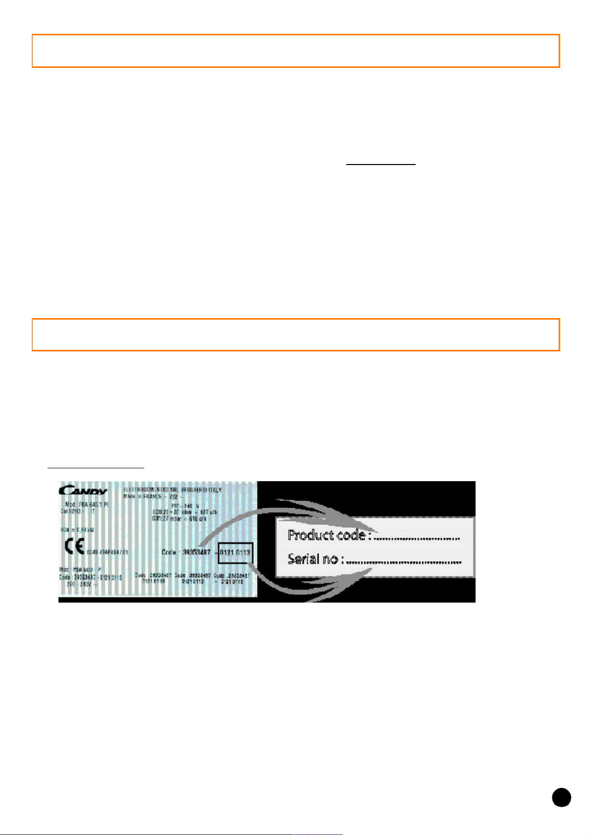
Please keep the operating and installation instructions in a safe place for all further needs,
and note, before fixing the hob, the serial number of the appliance in case you may request
repairs from after sales service.
. Data plate (located under the lower casing of the hob)
• All accessible parts of the hob become hot while it is operating. Keep children
away from it.
• It is recommended that the hob should be given a quick clean after every usage, to avoid
accumulation of spillages and grease, which if not removed, will harden, producing smoke
and unpleasant smells.
• When cooking with fats or oils, never leave gas burner unattented. Overheated fats or oils
can quickly catch fire.
21
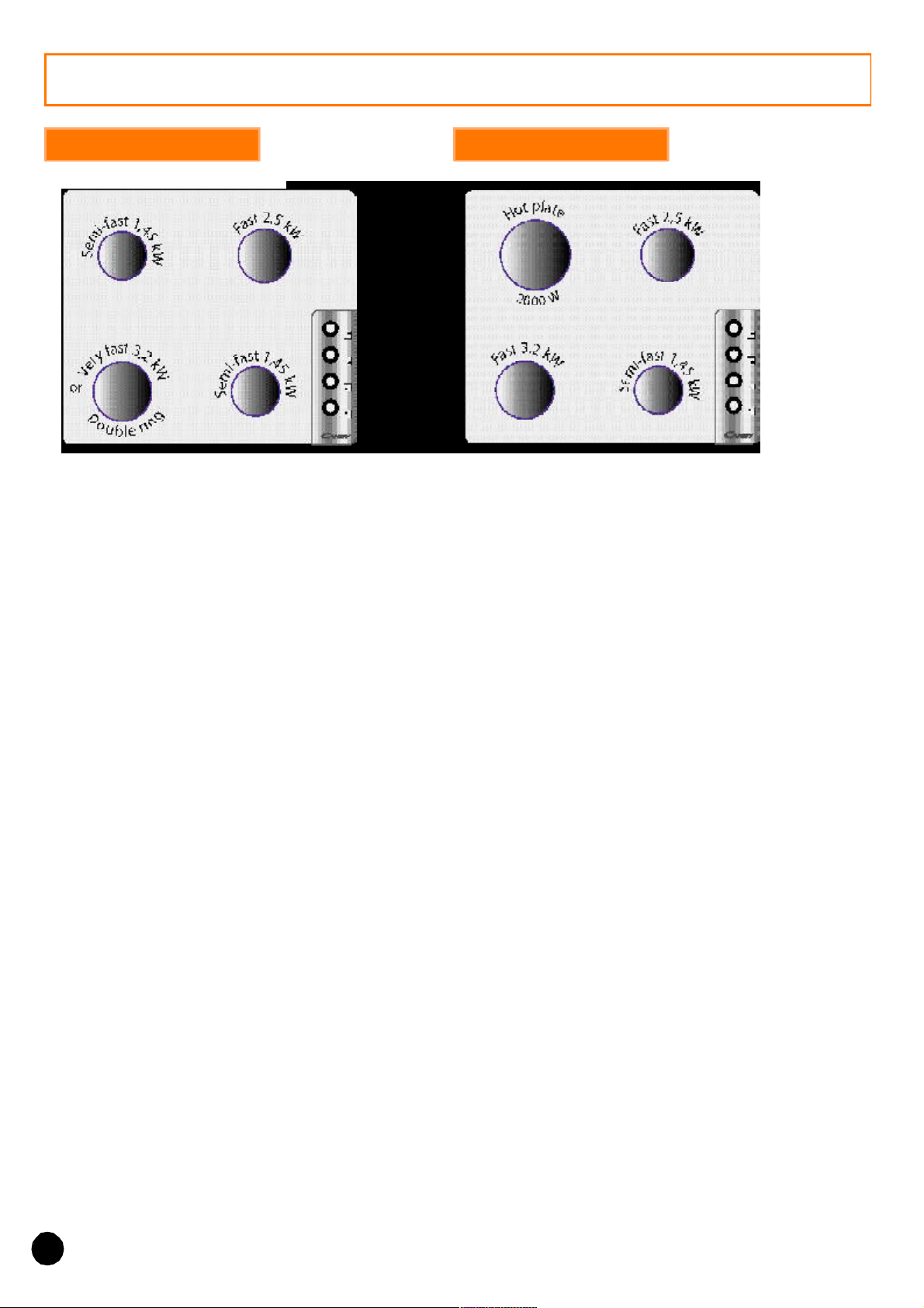
PRESENTATION
ALL GAS HOB
TOUT GAZ
PA 640/2 F : 4 gas burners, and cast-iron pan supports.
PLA 640 : 4 gas burners, and enamelled steel pan supports.
MIXED HOB
PLAS 640 : 4 gas burners, safety device, and cast-iron or chrome
steel pan supports according to colour.
PLA 631 : 3 gas burners +1 hot plate 2000 W, and enamelled
steel pan supports.
PSA 640/2 : 4 gas burners, safety device and enamelled steel pan supports.
PSA 640/2 F : 4 gas burners, safety device, and cast-iron pan supports.
PLDA 640 - PLDA 640 NL : 4 gas burners with 1 double ring, and enamelled steel
pan supports.
PLDAS 640 : 4 gas burners, safety device, with 1 double ring, and enamelled
steel pan supports.
Overall dimensions :
Width : 59 cm Depth : 51 cm Height : 3 cm
22
Building-in dimensions - (see chapter "Installation")
Width : 56 cm Depth : 48 cm
INSTALLATION
Installing a domestic appliance can be a complicated operation which if not
carried out correctly, can seriously affect consumer safety.
It is for this reason that the task should be undertaken by a professionnally
qualified person who will carry it out in accordance with the technical regulations
in force.
In the event that this advice is ignored and the installation is carried out by an
unqualified person, CANDY declines all responsibility for any technical failure
of the product whether or not it results in damage to goods or injury to
individuals.
'
'
Before installing the hob :
! make sure that the appliance is compatible with the gas supply source.
The hob is pre-set in the factory to work with the type of gas shown on the packing
and the plate attached to it.
Natural gas G 20-20 mbar / G 25-25 mbar : mains gas
" if necessary, adapt the hob for use with another t ype of gas : if the hob
must be used with another type of gas than the gas pre-set in the factory, it is necessary
to adapt the hob gas burners (page 24/25).
The procedure for adaptation consists of :
. fitting the correct jets to ensure nominal delivery,
. adjusting the appearance of the flame by regulating the air ring according to the
data given in the table.
For installation :
# built-in the hob (page 26/27).
$ make the gas connection according to the type of gas to be used : based on
the gas to be used, choose the appropriate gas connection (page 28).
Warning :
special instructions in page 28.
% make the hob electrical connection according to the instructions (page
29).
& adjusting the minimum flame of the taps : if necessary, adjust the minimum
flame of the taps by turning the by-pass screw (page 30).
All modification concerning the hob gas setting must be indicated on the plate sticked
on the hob.
certain countries request the setting of a tapered connector. Follow the
23
INSTALLATION: "GAS CONNECTION"
• CHANGING GAS TYPE : the calorific power output and gas pressure will vary
according to the gas supply. Burner setting must be carried out once the gas and electrical
installation is complete.
When changing gas type, you must successively :
. fit the correct jets,
. adjust the appearance of the flame by regulating the air ring.
. adjust the minimum flame of the taps (see page 30).
• CHANGING THE JETS :
Each jet is designed by a size. A special spanner supplied with the appliance is designed to
hold the jets securely during the set up operation.
To gain access to these jets :
. remove the pan support,
. remove the burner cap and body,
. using the spanner supplied with the appliance, unscrew
the jet,
. refit the correct jet for the type of gas to be used,
. screw it or them fully,
. replace the burner body, cap and the pan support.
Example : Fast or Double ring gas burner 3,2 kW
Burner
body
Jet
24
INSTALLATION: "GAS CONNECTION"
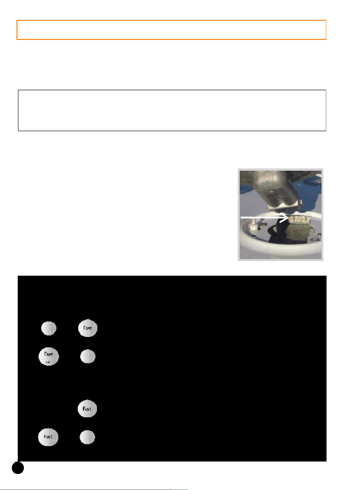
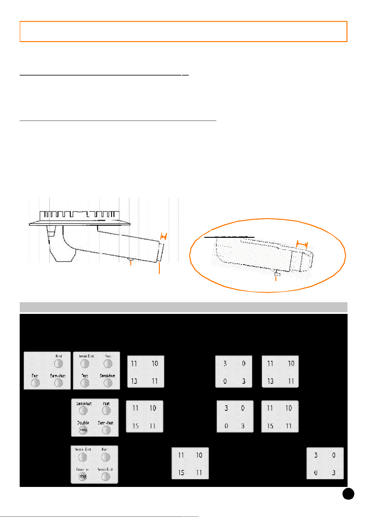
• SETTING THE APPEARANCE OF THE FLAME
1. Regulating the air ring on the hob burners : its setting is important as it permits correct
combustion and enables the burners to work at maximum efficiency. The table mentions
the value "X" in mm ; it may be necessary to regulate this by plus or minus 1 mm to obtain
a perfect flame.
2. To gain access to the air rings on the hob burners:
remove the pan support, the burner
cap and body of the relevant burner. The air ring is located at the lengthening of the burner
unit which is fixed by a screw (see drawing).
If necessary : . unscrew the screw that holds the air flow adjuster,
. set the correct distance according to the air adjuster protrudes,
. secure the screw when the operation is completed.
Semi-fast burner 1,45 kW
or Fast burner 2,5 kW
Quota
X
Screw
Air ring
Fast burner 3,2 kW and
Fast double ring 3,2 kW
Quota
X
Air
ring
Screw
Quota "X" in mm of the air ring according to the gas setting
25
 Loading...