

Page 1

INSTRUCTION FOR THE INSTALLATION ANDINSTRUCTION FOR THE INSTALLATION AND
INSTRUCTION FOR THE INSTALLATION AND
INSTRUCTION FOR THE INSTALLATION ANDINSTRUCTION FOR THE INSTALLATION AND
OPERATION OF HOBSOPERATION OF HOBS
OPERATION OF HOBS
OPERATION OF HOBSOPERATION OF HOBS
~~~
PA 640/2 F PA 640/2 F
PA 640/2 F
PA 640/2 F PA 640/2 F
PA 640/2 UK PA 640/2 UK
PA 640/2 UK
PA 640/2 UK PA 640/2 UK
93786974
11
1
11
Page 2

CONTENTSCONTENTS
CONTENTS
CONTENTSCONTENTS
Unpacking the appliance ...............................................................3
Recommendations ....................................................................... 3
Presentation of the hob / Technical data .......................................... 4
• INSTALLATION
Safety instructions........................................................................ 5
Modification of the factory gas setting :
* Fitting of the correct jets ........................................................ 6
* Adjusting of the air ring ......................................................... 7
Fitting the hob ........................................................................ 8/9
Gas connection ......................................................................... 10
Electrical connection .................................................................. 11
After final installation of the hob (if modification of the gas setting) :
Adjusting of the lower flame on the gas burners .............................. 12
• USING THE APPLIANCE
The different gas burners ............................................................ 13
Igniting and setting the burner ..................................................... 14
General maintenance .................................................................. 15
22
2
22
Page 3
UNPACKING THE APPLIANCEUNPACKING THE APPLIANCE
UNPACKING THE APPLIANCE
UNPACKING THE APPLIANCEUNPACKING THE APPLIANCE
Inside the appliance, you will find :
• a plastic bag containing :
- the new jets for the gas modification, if required,
- the fixing brackets with screws to install the hob in the worktop,
and,
• a spanner to change the jets if the factory gas setting does not correspond to your
installation requirements.
RECOMMENDATIONSRECOMMENDATIONS
RECOMMENDATIONS
RECOMMENDATIONSRECOMMENDATIONS
PLEASE READ THE FOLLOWING CAREFULLY IN ORDER TO GET THE BEST FROM
YOUR APPLIANCE.
Please keep the operating and installation instructions in a safe place for future reference.
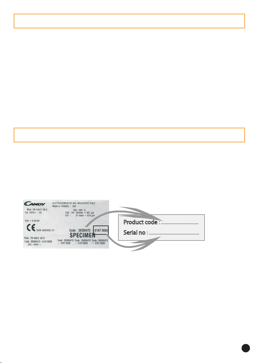
Before fixing the hob, note the serial number of the appliance just in case you may require
future repairs from after sales service organisation.
. Rating plate (located under the lower casing of the hob)
• All accessible parts of the hob become hot while it is in operation. Always, keep
children away from it.
• The hob should be given a quick clean after each use, to avoid the accumulation of
spillages and grease, which if not removed, will harden and could cause the production of
smoke and unpleasant smells.
• When cooking with fats or oils, never leave gas burner unattended. Overheated fats or
oils can quickly catch fire.
33
3
33
Page 4
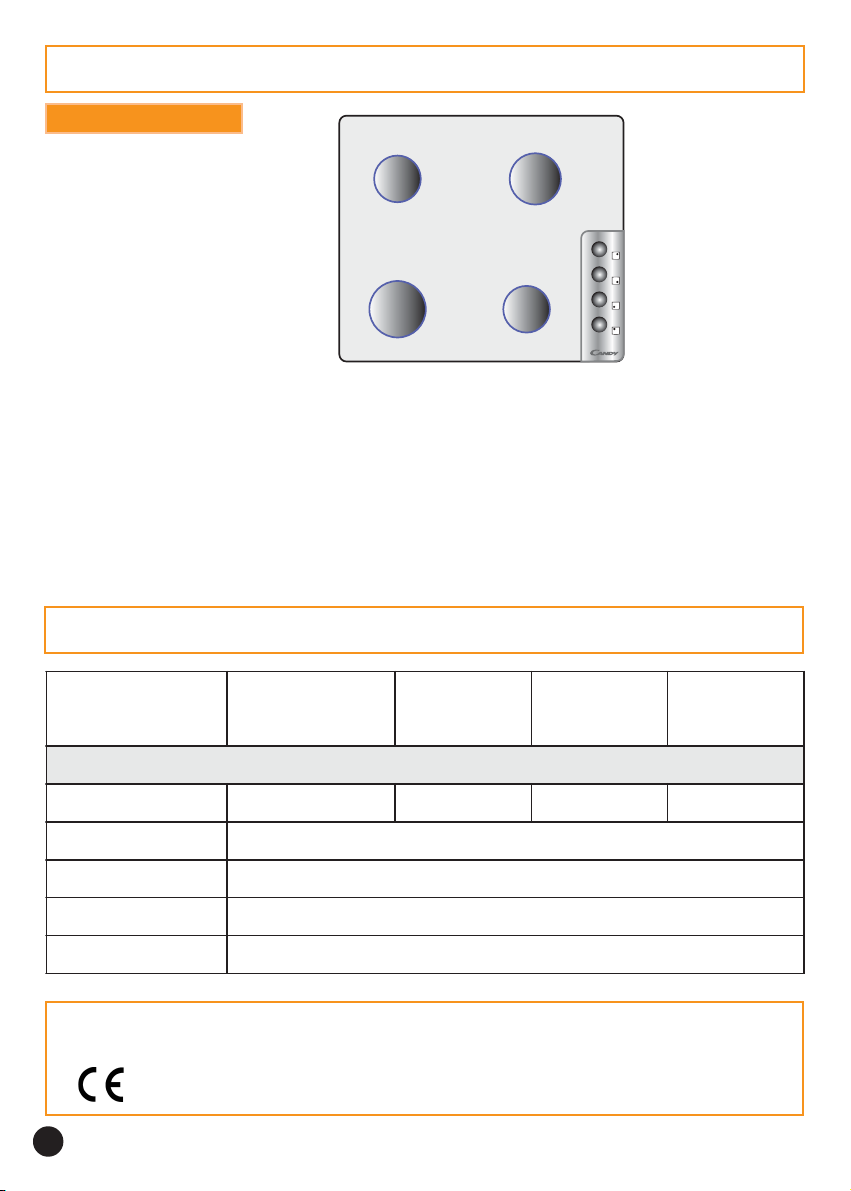
PRESENTATION
ALL GAS HOB
2
,
5
TOUT GAZ
PA 64PA 64
0/2 F :0/2 F :
PA 64
0/2 F :
PA 64PA 64
0/2 F :0/2 F :
PA 64PA 64
0/2 UK :0/2 UK :
PA 64
0/2 UK :
PA 64PA 64
0/2 UK :0/2 UK :
OveralOveral
Overal
OveralOveral
l dimensions :l dimensions :
l dimensions :
l dimensions :l dimensions :
t
s
1
a
f
,
4
-
i
5
m
k
e
W
S
t
s
3
a
f
,
2
y
k
r
e
V
4 gas burners, and cast-iron pan supports.4 gas burners, and cast-iron pan supports.
4 gas burners, and cast-iron pan supports.
4 gas burners, and cast-iron pan supports.4 gas burners, and cast-iron pan supports.
4 gas burners, and enamelled pan supports.4 gas burners, and enamelled pan supports.
4 gas burners, and enamelled pan supports.
4 gas burners, and enamelled pan supports.4 gas burners, and enamelled pan supports.
W
t
s
k
a
W
F
t
1
s
,
a
4
f
5
-
i
k
m
W
e
S
Width : 59 cm Depth : 51 cm Height : 3 cm
Building-in dimensions Building-in dimensions
Building-in dimensions
Building-in dimensions Building-in dimensions
- -
- (see chapter "Installation")
- -
Width : 56 cm Depth : 48 cm
TECHNICAL DATA
renrubtsaF
tfeltnorf
tsaf-imeS
renrub
tfelraer
renrubtsaF
thgirraer
renruftsaf-imeS
thgirtnorf
KU2/046AP-F2/046APKU2/046AP-F2/046AP
KU2/046AP-F2/046APKU2/046AP-F2/046AP
KU2/046AP-F2/046AP
Wk2,3Wk54,1Wk5,2Wk54,1
rabm02-02G
rabm52-52G
rabm03-8203G
rabm7313G
h/l918
h/l379
h/g726
h/g616
In order to improve the quality of the products, CANDY may carry out modifications linked
to technical improvements.
Appliance meeting with the standard CEE 89/336, 73/23 and 90/396.
44
4
44
Page 5
INSTALLATIONINSTALLATION
INSTALLATION
INSTALLATIONINSTALLATION
Installing a domestic appliance can be a complicated operation which if not
carried out correctly, can seriously affect consumer safety.
It is for this reason that the task should be undertaken by a professionally
qualified person who will carry it out in accordance with the technical regulations
in force.
In the event that this advice is ignored and the installation is carried out by an
unqualified person, CANDY declines all responsibility for any technical failure
of the product whether or not it results in damage to goods or injury to
individuals.
Before installing the hob :
)
n make sure that the appliance is compatible with the gas supply source.
The hob is pre-set in the factory to work with the type of gas shown on the packing
and the plate attached to it.
Natural gas G 20-20 mbar / G 25-25 mbar : mains gas
o if necessary, adapt the hob for use with another type of gas : if the hob
must be used with another type of gas than the gas pre-set in the factory, it is necessary
to adapt the hob gas burners (page 6/7).
The procedure for adaptation consists of :
. fitting the correct jets to ensure nominal delivery,
. adjusting the appearance of the flame by regulating the air ring according to the
data given in the table.
For installation :
)
p built-in hob (page 8/9).
q make the gas connection according to the type of gas to be used : based on
the gas to be used, choose the appropriate gas connection (page 10).
r make the hob electrical connection according to the instructions (page
11).
s adjusting the minimum flame of the taps : if necessary, adjust the minimum
flame of the taps by turning the by-pass screw (page 12).
All modification concerning the hob gas setting must be indicated on the rating plate
of the hob.
55
5
55
Page 6

INSTALLATION:
"GAS CONNECTION""GAS CONNECTION"
"GAS CONNECTION"
"GAS CONNECTION""GAS CONNECTION"
• CHANGING THE GAS TYPE : the calorific power output and gas pressure will
vary according to the gas supply. Burner setting must be carried out once the gas and
electrical installation is complete.
When changing gas type, you must follow the procedure below :
. fit the correct jets,
. adjust the appearance of the flame by regulating the air ring.
. adjust the minimum flame on the taps (see page 12).
• CHANGING THE JETS :
Each jet is designated by size. A special spanner supplied with the appliance is designed to
hold the jets securely during the set up operation.
To gain access to the jets :
. remove the pan supports,
. remove the burner cap and body,
. using the spanner supplied with the appliance, unscrew
the jet,
. fit the correct jet for the type of gas to be used,
. secure the jet tightly,
. replace the burner body, cap and the pan support.
G20-20 mbar / G25-25 mbar
4 gas burners
1,45 kW 2,5 kW
Semi-
fast
3,2 kW
Fast
Fast
1,45 kW
Semi-
fast
Jet
96
Jets
94 x 2
Jet
122
Jet
96
Burner
body
Jet
Example : Fast ring gas burner 3,2 kW
G30 28-30 mbar
G31 37 mbar
Jet
61
Jets
65 x 2
Jet
80
Jet
61
66
6
66
Page 7

INSTALLATION:
"GAS CONNECTION""GAS CONNECTION"
"GAS CONNECTION"
"GAS CONNECTION""GAS CONNECTION"
• SETTING THE APPEARANCE OF THE FLAME
1. Regulating the air ring on the hob burners : the setting is important as it ensures the
correct combustion and enables the burners to work at maximum efficiency. The table
refers to the value "X" in mm ; it may be necessary to regulate this by plus or minus 1 mm
to obtain a perfect flame.
2. To gain access to the air rings on the hob burners: remove the pan support, the burner
cap and body of the relevant burner. The air ring is located at the lengthening of the burner
unit which is fixed by a screw (see drawing).
If necessary : . unscrew the screw that holds the air flow adjuster,
. set the correct distance according to the air adjuster protrudes,
. secure the screw when the operation is completed.
Semi-fast burner 1,45 kW
or Fast burner 2,5 kW
Quota
X
Fast burner 3,2 kW
Quota
X
Air
ring
Screw
Air ring
Screw
Quota "X" in mm of the air ring according to the gas setting
Semi-fast Fast
Fast
Semi-fast
G20-20 mbar
G25-25 mbar
6 10
14 6
G30 28-30 mbar G31 37 mbar
00
00
7 9
14 7
77
7
77
Page 8

INSTALLATION:
BUILDING-IN :BUILDING-IN :
BUILDING-IN : both the unit into which the hob will be fitted and any adjacent kitchen
BUILDING-IN :BUILDING-IN :
furniture must be made from heat resistant material and fixed with heat resistant adhesive.
If, when installing the hob, the lower part of the casing is adjacent to an area normally
accessible when handling or cleaning, fit a partition 1 cm below the base of the casing with
a 10x10 cm opening at the rear right-hand corner, to avoid any risk of burning or damage.
There should also be a 5 cm gap between the appliance and all adjacent vertical surfaces.
A foam adhesive is supplied with the hob. Stick this seal under the edge of the body as near
as possible to the outer edge of the hob. Press round the edges of the hob, so that the seal
flattens out and ensures an air tight seal.
Warning :Warning :
Warning : at the rear of the appliance, take care not to block the air inlets necessary for
Warning :Warning :
combustion to take place.
FITTING THE SEALFITTING THE SEAL
FITTING THE SEAL
FITTING THE SEALFITTING THE SEAL
• •
Top view of the sealTop view of the seal
•
Top view of the seal
• •
Top view of the sealTop view of the seal
"BUILDING-IN""BUILDING-IN"
"BUILDING-IN"
"BUILDING-IN""BUILDING-IN"
• •
Cross section of the hobCross section of the hob
•
Cross section of the hob
• •
Cross section of the hobCross section of the hob
seal
88
8
88
6 mm
SEAL
Worktop levelWorktop level
Worktop level
Worktop levelWorktop level
- Take care not to block the air inlets- Take care not to block the air inlets
- Take care not to block the air inlets
- Take care not to block the air inlets- Take care not to block the air inlets
necessary for combustion to take place -necessary for combustion to take place -
necessary for combustion to take place -
necessary for combustion to take place -necessary for combustion to take place -
Page 9

INSTALLATION:
The body of the hob is fitted with 4 location holes to take the fixing brackets that secure the
hob in the unit. Place the 4 fixing brackets in such a way that the hob is placed perfectly in
the support unit.
Location for fixing bracketsLocation for fixing brackets
Location for fixing brackets
Location for fixing bracketsLocation for fixing brackets
Fixing
bracket
"BUILDING-IN""BUILDING-IN"
"BUILDING-IN"
"BUILDING-IN""BUILDING-IN"
Building-in according to TYPE XBuilding-in according to TYPE X
Building-in according to TYPE X
Building-in according to TYPE XBuilding-in according to TYPE X
(Norm CEI 335-2-6)(Norm CEI 335-2-6)
(Norm CEI 335-2-6)
(Norm CEI 335-2-6)(Norm CEI 335-2-6)
Opening
10x10 cm
99
9
99
Page 10

INSTALLATION:
The hob can be built-in ; it is type "X" for built-in hob (in compliance with electrical
regulations EN 60.335.2.6) ; in class 3 (in compliance with gas norm EN 30.1.1) ;
adjoining furniture should not be higher than the level of the hob.
This appliance is not connected to an evacuation device for the products of combustion. It
must be installed and connected in compliance with the norms in force in the country of
installation. Particular attention should be given to the availability of ventilation. The turnover of air necessary for combustion is a minimum of 2 m3/h per kW of power.
Gas connection should be carried out in compliance with the norms in force in the
country of installation. A stop tap, a regulator valve or a release valve for propane gas,
should be fitted to the gas supply pipe. Use only taps, regulator valves, connectors and
flexible hoses with the official mark of approval of the country of installation.
"GAS CONNECTION""GAS CONNECTION"
"GAS CONNECTION"
"GAS CONNECTION""GAS CONNECTION"
¾ CONNECT DIRECTLY TO THE THREADED END OF THE INLET
PIPE ISO 7-1.
1010
10
1010
Page 11

INSTALLATION:
The mains electricity supply connected to the appliance should comply with the norms in
force in the country of installation.
Connection to the mains electricity supply should be through a socket with an earth terminal,
or through an intermediary switching device with a gap between contacts of at least 3 mm.
The power supply unit must be protected by appropriate fuses and use cables of a large
enough cross section to provide a normal supply to the appliance.
The hob is fitted with a power supply cable* which allow it to be connected only to a power
supply of 230 V between phases, or between phase and neutral.
• Connect to a 10/16 Amp socket. Before connecting, it is compulsory• Connect to a 10/16 Amp socket. Before connecting, it is compulsory
• Connect to a 10/16 Amp socket. Before connecting, it is compulsory
• Connect to a 10/16 Amp socket. Before connecting, it is compulsory• Connect to a 10/16 Amp socket. Before connecting, it is compulsory
to check :to check :
to check :
to check :to check :
. the power supply voltage shown on the electricity meter,
. the adjustment of the circuit breaker, and
. the fuse rating 10A.
Note : the socket must be reachable for any eventual repair. Take care of its location
at the time you install the hob.
Warning : before proceeding with the connection, check the continuity of theWarning : before proceeding with the connection, check the continuity of the
Warning : before proceeding with the connection, check the continuity of the
Warning : before proceeding with the connection, check the continuity of theWarning : before proceeding with the connection, check the continuity of the
earthing of the power supply unit.earthing of the power supply unit.
earthing of the power supply unit.
earthing of the power supply unit.earthing of the power supply unit.
We cannot be held responsible for any accident which has resulting from the useWe cannot be held responsible for any accident which has resulting from the use
We cannot be held responsible for any accident which has resulting from the use
We cannot be held responsible for any accident which has resulting from the useWe cannot be held responsible for any accident which has resulting from the use
of an appliance which is not connected to earth, or whose earthing is defective.of an appliance which is not connected to earth, or whose earthing is defective.
of an appliance which is not connected to earth, or whose earthing is defective.
of an appliance which is not connected to earth, or whose earthing is defective.of an appliance which is not connected to earth, or whose earthing is defective.
"ELECTRICAL CONNECTION"ELECTRICAL CONNECTION
"ELECTRICAL CONNECTION
"ELECTRICAL CONNECTION"ELECTRICAL CONNECTION
""
"
""
* The eventual replacement of the supplying cord must be carried on by the After Sales
Service or by an agreed engineer, with a cord whose characteristics must be similar to the
original one : cord type H05 V2V2-F, 3 G 0,75 section.
1111
11
1111
Page 12

INSTALLATION:
"REGULATING THE FLAME""REGULATING THE FLAME"
"REGULATING THE FLAME"
"REGULATING THE FLAME""REGULATING THE FLAME"
• SETTING THE IDLE FLAME
If you have changed the type of gas, it is important to verify the flame stability at the
minimum regulation.
"Gaining access to the by-pass screw"
To gain access to hob burner by-pass screws, remove the knobs from the control panel.
By-pass screw of the hob burner
!
Never loosen
the others screws !
REGULATING THE MINIMUM FLAME ON THE HOB BURNER
a) Natural gas :
. simply loosen the screw.
. switch on the burner and turn the knob to minimum.
. Turn the by-pass screw until a low flame is visible. Turn the control knob from
minimum to maximum position to check that it is satisfactory.
b) Butane-propane gas :
The by-pass screw should be screwed fully home, without being locked.
1212
12
1212
Page 13

THE GAS BURNERTHE GAS BURNER
THE GAS BURNER
THE GAS BURNERTHE GAS BURNER
THE VERY FAST "DOUBLE RING" BURNER has a power rating of 3,2 kW :THE VERY FAST "DOUBLE RING" BURNER has a power rating of 3,2 kW :
THE VERY FAST "DOUBLE RING" BURNER has a power rating of 3,2 kW :
THE VERY FAST "DOUBLE RING" BURNER has a power rating of 3,2 kW :THE VERY FAST "DOUBLE RING" BURNER has a power rating of 3,2 kW :
Use the large burner for bringing to the boil, for cooking large quantities, and generally for
all foods requiring rapid cooking.
THE FAST BURNER has a power rating of 2,5 kW :THE FAST BURNER has a power rating of 2,5 kW :
THE FAST BURNER has a power rating of 2,5 kW :
THE FAST BURNER has a power rating of 2,5 kW :THE FAST BURNER has a power rating of 2,5 kW :
It is ideal for stewing, sauces and slow cooking.
THE SEMI-FAST BURNER has a power rating of 1,45 kW :THE SEMI-FAST BURNER has a power rating of 1,45 kW :
THE SEMI-FAST BURNER has a power rating of 1,45 kW :
THE SEMI-FAST BURNER has a power rating of 1,45 kW :THE SEMI-FAST BURNER has a power rating of 1,45 kW :
Use this small burner for small pans.
For a proper use of the burners, choose pans which match the dimensions given below :
* Very fast* Very fast
* Very fast
* Very fast* Very fast
* Fast* Fast
* Fast
* Fast* Fast
* Semi-fast* Semi-fast
* Semi-fast
* Semi-fast* Semi-fast
On model fitted with cast iron pan supports,
we supply a reduction pan support to use pans with
dimensions of less than Ø 12 cm.
Ø 18 cm and moreØ 18 cm and more
Ø 18 cm and more
Ø 18 cm and moreØ 18 cm and more
Ø from 16 to 18 cmØ from 16 to 18 cm
Ø from 16 to 18 cm
Ø from 16 to 18 cmØ from 16 to 18 cm
Ø 12 cmØ 12 cm
Ø 12 cm
Ø 12 cmØ 12 cm
SOME TIPSSOME TIPS
SOME TIPS
SOME TIPSSOME TIPS
• Pans with curved, ridged or warped bottoms are not recommended.
• Avoid boiling food too intensely. Food is not cooked any more quickly this way. In fact,
it is subjected to severe agitation, which may cause the food to lose some of its flavour.
••
• To save gas, make sure that the flames do not overlap the bottom of the pan.
••
• Do not use the gas burner with an empty pan.
RECOMMENDATIONS : when the burners are not in service, the general gasRECOMMENDATIONS : when the burners are not in service, the general gas
RECOMMENDATIONS : when the burners are not in service, the general gas
RECOMMENDATIONS : when the burners are not in service, the general gasRECOMMENDATIONS : when the burners are not in service, the general gas
supply tap should always be turned off.supply tap should always be turned off.
supply tap should always be turned off.
supply tap should always be turned off.supply tap should always be turned off.
.... ....
....
.... ....
1313
13
1313
Page 14

THE GAS BURNERTHE GAS BURNER
THE GAS BURNER
THE GAS BURNERTHE GAS BURNER
Each burner is contolled by a tap with progressive settings allowing :
* a wider choice of settings from the maximum position to the lowest and most precise one,
* easier flame regulation according to the pan diameter,
* no risk of cutting off the flame or switching off when the flame is turned down quickly.
Each burner is fitted with automatic ignition. The ignition can be made with one hand, while
you have the pan in the other hand.
USE :USE :
USE :
USE :USE :
• Turn on the gas tap,
• •
• A symbol next to each control knob indicates which burner is lit.
• •
Hob with automatic ignition integrated on the knob :
• Press and turn the knob until position
to produce sparks which in turn ignite the burner.
Hob with safety device on the burner and automatic ignition integrated on the
knob :
The thermocouple fast safety is a device allowing the automatic cut-out of the gas
supplying on the burner, in case the flame dies out accidentally.
• Press and turn the knob to position
produce sparks which in turn ignite the burner. Keep the pressure on the control knob
a few seconds to permit the releasing of the safety device.
"High flame" "High flame"
"High flame" or
"High flame" "High flame"
"High flame" "High flame"
"High flame" or
"High flame" "High flame"
"+" "+"
"+" keeping it pressed
"+" "+"
"+" "+"
"+" keeping it pressed to
"+" "+"
1414
14
1414
• Set the flame according to your cooking requirements.
Intermediate positions are available between the
flame" flame"
flame" or
flame" flame"
• To turn the flame out, turn the control knob back to stop position.
Please note :
If there is a power cut, the burner can be ignited by pressing in and turning the knob
to position
"-" "-"
"-" settings on the control knob.
"-" "-"
"High flame"High flame
"High flame
"High flame"High flame
""
"+""+"
" or
"+" and holding a naked flame to the burner.
""
"+""+"
"High flame" "High flame"
"High flame" or
"High flame" "High flame"
"+" "+"
"+" and
"+" "+"
"Low"Low
"Low
"Low"Low
Page 15

CLEANING
Before all cleaning or dismantling operation, it is imperative to :Before all cleaning or dismantling operation, it is imperative to :
Before all cleaning or dismantling operation, it is imperative to :
Before all cleaning or dismantling operation, it is imperative to :Before all cleaning or dismantling operation, it is imperative to :
. disconnect the hob to the mains supply,. disconnect the hob to the mains supply,
. disconnect the hob to the mains supply,
. disconnect the hob to the mains supply,. disconnect the hob to the mains supply,
. let all parts of the hob cool down. let all parts of the hob cool down
. let all parts of the hob cool down
. let all parts of the hob cool down. let all parts of the hob cool down
..
.
..
Never useNever use
Never use
Never useNever use
• •
GENERAL MAINTENANCEGENERAL MAINTENANCE
•
GENERAL MAINTENANCE
• •
GENERAL MAINTENANCEGENERAL MAINTENANCE
: :
harsh abrasives, scouring pads or sharp object to clean the hob. harsh abrasives, scouring pads or sharp object to clean the hob.
:
harsh abrasives, scouring pads or sharp object to clean the hob.
: :
harsh abrasives, scouring pads or sharp object to clean the hob. harsh abrasives, scouring pads or sharp object to clean the hob.
THE HOB
. Enamelled steel hob : simply clean the enamelled hob with soapy water when the hob is
cold, rinse and wipe with a clean dry cloth. If you clean the enamelled hob when it is hot,
you may tarnish it.
. Stainless steel : clean with soapy water, rinse and dry. You can use a special product to
clean stainless steel which is available in stores.
THE KNOBSTHE KNOBS
THE KNOBS - For thorough cleaning, the control knobs can be removed by pulling them
THE KNOBSTHE KNOBS
upwards. Clean with soapy water, rinse and dry well before replacing.
THE GAS BURNERSTHE GAS BURNERS
THE GAS BURNERS
THE GAS BURNERSTHE GAS BURNERS
For cleaningFor cleaning
For cleaning, it is recommended to remove all greasy or burnt deposits with ammonia
For cleaningFor cleaning
based products or usual cleaning products.
• The burner cap : it is simply placed on the burner.
Remove the pan support, the burner cap and clean it with a slightly soapy sponge. Rinse
and dry.
The enamelled steel burner cap : do not immerse it in cold water when it is hot, this will
prevent the enamel cracking as a result of thermal shock.
• The burner body : regular cleaning will maintain the appliance original appearance.
Clean with a soapy sponge, rinse and dry. If the holes become clogged, brush the caps using
soapy water and dry with a clean cloth.
When re-assembling the burners, When re-assembling the burners,
When re-assembling the burners,
When re-assembling the burners, When re-assembling the burners,
make sure that the burner caps and the burners
themselves are dry and after, seat them correctly.
Be careful not to let any water get into the burners.Be careful not to let any water get into the burners.
Be careful not to let any water get into the burners.
Be careful not to let any water get into the burners.Be careful not to let any water get into the burners.
THE PAN SUPPORTTHE PAN SUPPORT
THE PAN SUPPORT
THE PAN SUPPORTTHE PAN SUPPORT
Depending on the model, the pan supports are made of enamelled steel or cast-iron.
They are simply placed on the hob. Lift them up to remove them.
For the maintenance of the pan support, never use harsh abrasives, scouring pads or sharp
objects as this will cause irreparable damage to the enamel.
When the pan support is cold, simply clean with soapy water, rinse and dry with a clean
cloth.
1515
15
1515
Page 16

1616
16
1616
CANDY ELETTRODOMESTICI S.R.L.CANDY ELETTRODOMESTICI S.R.L.
CANDY ELETTRODOMESTICI S.R.L.
CANDY ELETTRODOMESTICI S.R.L.CANDY ELETTRODOMESTICI S.R.L.
BRUGHERIO (MILANO)
ITALIA
 Loading...