

Page 1

VISUALIZATION DISPLAY UNIT
OPERATING INSTRUCTIONS
Table of Contents
1)CamTrace VU.......................................................................2
1)First steps:...............................................................................................................................................3
a)“CamTrace Client” mode............................................................................................................4
b)“VU Standalone” mode ...............................................................................................................6
2)F.A.Q ?...................................................................................9
1)Check the connectivity of the VU....................................................................................................9
2)Set up dual/multiple screens.............................................................................................................9
3)Connect your VU to a WiFi network...............................................................................................12
4)Create an USB key (and update your VU)...................................................................................15
5)Remote control..................................................................................................................................17
6)Create USB key under Microsoft Windows....................................................................................18
7)Reset your CamTrace VU.................................................................................................................19
User Documentation v1.1 - CamTrace VU v1.68 – July 2010 1/19
Page 2

1) CamTrace VU
CamTrace VU is a light and autonomous visualization system which can interface
• With a CamTrace server to be used as a controller and/or as a display station
• Or directly with one or several IP cameras provided by Axis, Sony or Mobotix.
There are two versions of CamTrace VU :
• a package with pre-installed equipment and software,
• or an autonomous USB key version to connect up to your PC
• or an ISO of CamTrace VU which you can download yourself an ISO of CamTrace VU,
wich you can copy on your USB key.
As a package provided by CamTrace, the VU allows accelerating the decompression
of videos to the H264 format thanks to its graphic card. Since CamTrace VU is already
installed in this configuration, you can skip directly to the next stage.
CamTrace VU uses a system called “Live”, that is to say that the memory is divided
into two distinct areas on the support:
• The first one is only related to the system, and is only accessible in read-only.
• The second storage area is alloted to the user to save sequences, configurations, etc.
Thus, CamTrace V U gets free of current defects existing in most of the operating
systems, even if some problems may occur. However, if your CamTrace VU seems to be in
trouble, just reinitialize it so as to have it in “Factory service Mode”
If you wish to use your own computer, note that the support of accelerated H264
decompression requires one of the latest versions of nVidia graphic card (ION or GeForce
8800 minimum).
Now, if your CamTrace VU was supplied on a USB key, or you've downloaded it
yourself, you have to make your computer start on the USB key. You must modify the first
peripheral on which the computer will try to start in the BIOS.
When the computer is started, a blue screen will ask for your serial number and your
licence. You can find the information about these numbers from CamTrace.
CamTrace will give you the information. If you don't have it at your disposal, CamTrace
VU will run in demo mode, which is available for use for two hours only. After this period of
two hours, VU will reinitialize its configuration and switch off.
User Documentation v1.1 - CamTrace VU v1.68 – July 2010 2/19
Page 3
1) First steps:
So now, you have become a user of the CamTrace V U sy stem .
The first dialog box appears only at the first start or after a reset. It enables you to select the
language to be used and the keyboard mapping.
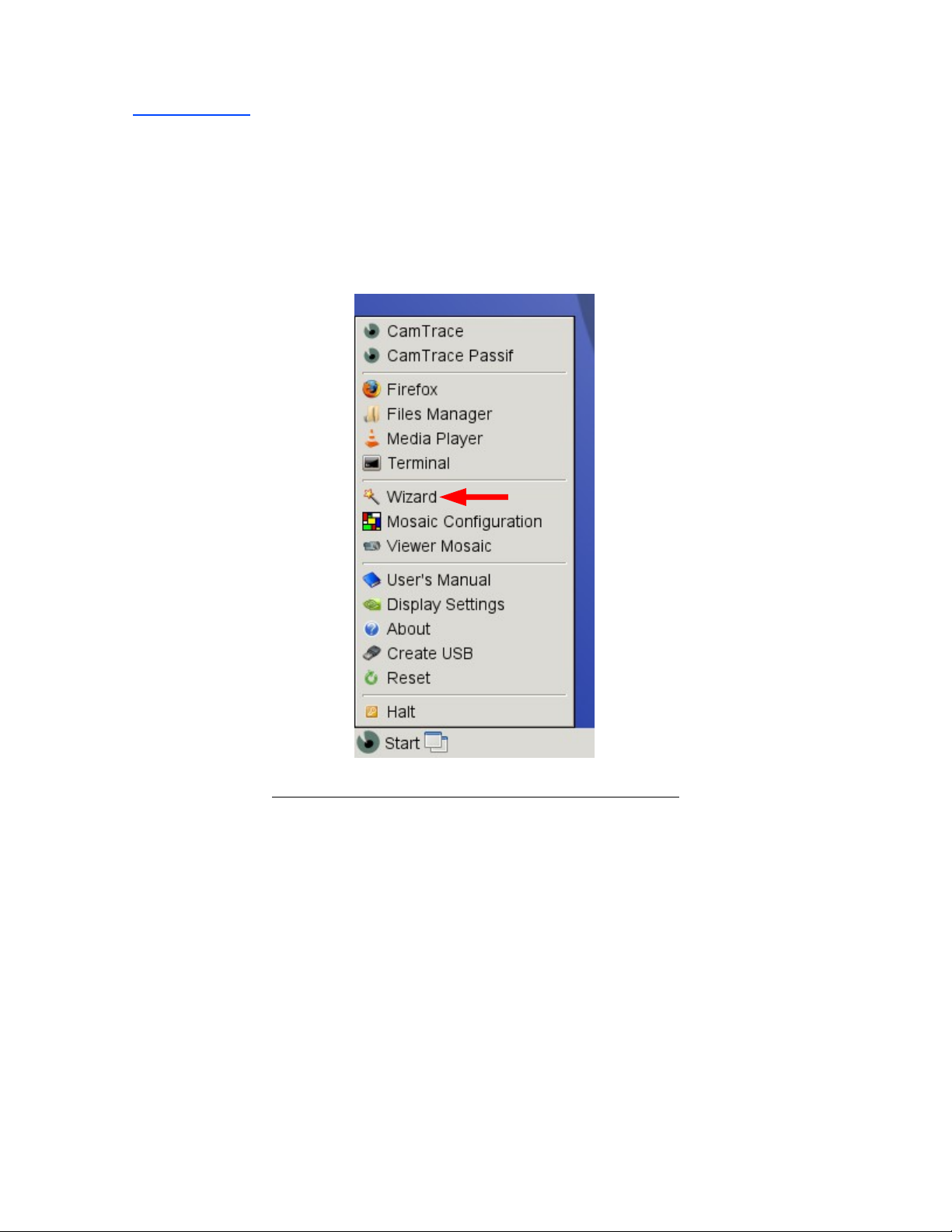
To configure the VU parameters, click on the label wizard which is available in the
menu and appears with its magic wand icon.
Screenshot of the « Start Menu » of CamTrace VU
This assistant is a guide for the basic tasks that are required for your VU to function:
• Your time zone
• Your network parameters
• Your operating mode (
User Documentation v1.1 - CamTrace VU v1.68 – July 2010 3/19
(to be updated automatically on your Camtrace server)
(IP address, netmask, gateway and DNS)
CamTrace Client or Standalone)
Page 4
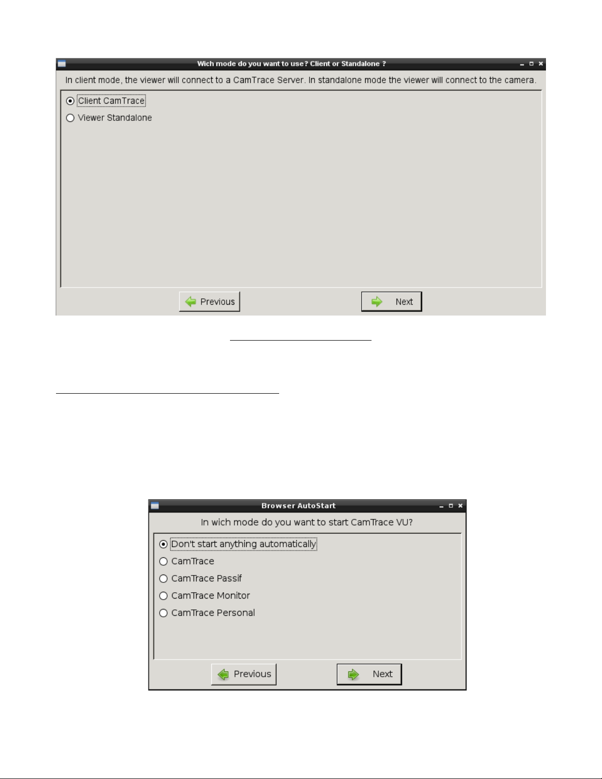
Choice of operating mode
When the time and network parameters are set, select the mode of use which you wish.
CamTrace offers you the choice between:
a)“
CamTrace Cl ient”
It needs a CamTrace server, the VU will connect to it and retrieve video streams from the
CamTrace server. The following settings allow you to set the IP address of your CamTrace
server, the display mode in which VU will load at boot (normal mode, passive mode or a
user's desktop set up in your CamTrace server configuration).
mod e.
User Documentation v1.1 - CamTrace VU v1.68 – July 2010 4/19
Page 5
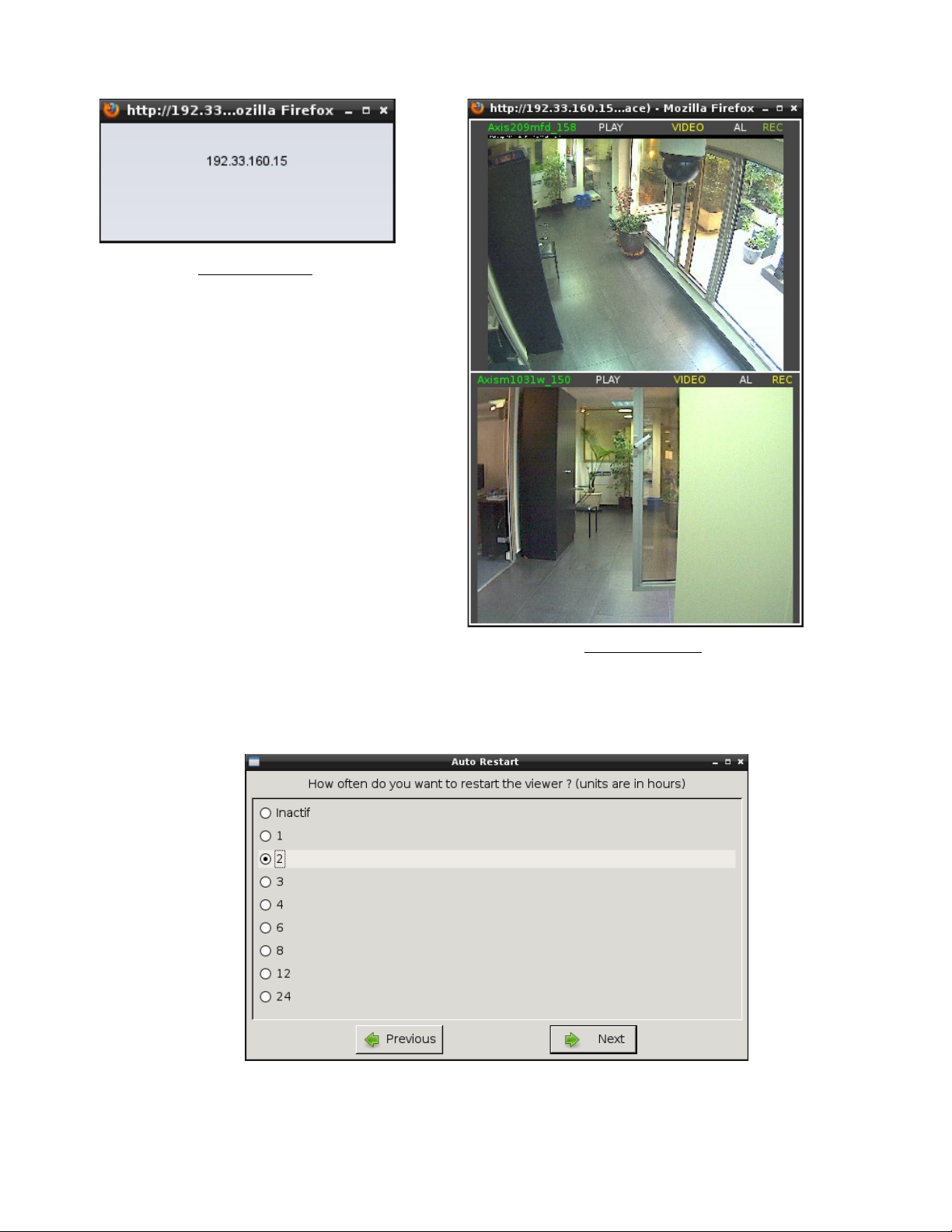
Passive mode
Monitor mode
A step in the assistant is also presented to select the re-launch frequency of the browser and
the starting time:
User Documentation v1.1 - CamTrace VU v1.68 – July 2010 5/19
Page 6
b) “VU Standalone ” mode
It allows to visualize your cameras in the form of mosaics which you can freely create.
This mode does not require a CamTrace server. Several H264 cameras can be visualized at
the same time in this mode thanks to the acceleration provided by the graphic card. The
assistant will launch the configuration software of mosaic.
Of course, this configuration tool is also available in the menu under the label “Mosaic
Configuration”, which allows the creation of numerous mosaics and skip the compulsory
stages of the assistant…).
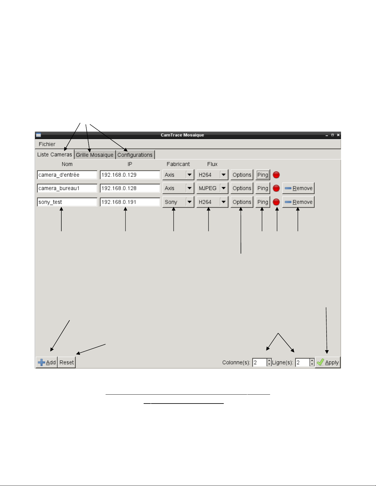
Tabs
Cameras name IP Address Constructor Stream Network test Delete line
Apply
configuration
Add cameras
Reset actual
Add or remove
columns and rows
configuration
Presentation of « Mosaic Configuration » tool ,
« List of cameras » tab
User Documentation v1.1 - CamTrace VU v1.68 – July 2010 6/19
Page 7

When the list of cameras is filled, click on
to the next tab entitled Mos ai c Grid. It presents a blank grid. A menu opens with a left click
on each box. It allows to
downward, left or rightward) or to
another box.
After your cameras are assigned according to your needs, you should come to a window
similar to this one:
« M erg e »
the box with another one in any direction (forward,
« A ssi gn »
« A pply »
a camera that formerly corresponded to
at the bottom on the right, and go
« Mosaic Configuration», Tab: «Mosaic Grid »
User Documentation v1.1 - CamTrace VU v1.68 – July 2010 7/19
Page 8

Just save this configuration by clicking in the menu
generate several grids, the Wizard allows you to select the one you wish to launch at your
computer boot.
The third tab on this window allows you to list your configurations and also to suppress
one or several if needed.
Your configurations will be saved in the
assistant will also enable you to regulate the stimulus frequency and the starting time, like in
CamTrace server mode.
At this stage, it is possible to use CamTrace VU straight away. If you wish to visualize the
pictures according to your grid, launch the
configuration in the
configured.
“cf g_m osaï c”
directory. You should get the view you have previously
« c fg_mosa ïc »
“Mo sai c Vi suali zati on ”
« Fi le » «→ Sa ve » .
directory of the user’s file. The
tool and select your
You also may
CamTrace VU : Standalone mode in function
User Documentation v1.1 - CamTrace VU v1.68 – July 2010 8/19
Page 9

2) F.A.Q ?
1) Check the connectivity of the VU
An icon positioned bottom right of the window, next to the clock, shows the state of
the network connection.
Network OK Network problem, please check your cables.
2) Set up dual/ multiple screens
With a nVidia card (recommended by CamTrace), launch the screen configuration software,
symbolised by a green icon in the menu.
Then, go to «
Con figuration »
screen parameters.
For example, this screenshot
shows that the configuration
tool only detects one screen.
(Dell)
If there should be another
screen, and it is not done
automatically, here is the
procedure to follow:
Select the button
Dis plays »
monitor appear on the layout.
X Serv er Dis play
to set the
« D etect
to make your extra
Cliquez ici pour
détecter vos écrans
User Documentation v1.1 - CamTrace VU v1.68 – July 2010 9/19
Page 10

First, click on the extra screen that appears: here,
« C onfi gure.. . »
The second screen is activated with this method and there only remains to add the
resolution settings before use. C amTr ace r ecom men ds to s et th e sa me res olu ti on o n
bot h screens to avoid display problems.
In this example, as the first screen was set in 1280x1024, the second one will be set with
the same parameters although it could display much higher resolutions.
and select
« T win Vi ew »
in the window that opens, and Validate.
SAMSUNG;
Next
,
click on the button
User Documentation v1.1 - CamTrace VU v1.68 – July 2010 10/19
Page 11

Just select the suitable resolution in the drop-down menu
In this example choose « 128 0x10 24 »
Click on the “Ap ply” button to enter the validating process. A window with a
countdown will ask you to validate your settings. If ever the multiple monitor display is
unreadable because of erroneous parameters, the VU automatically returns to the previous
acceptable display mode after twenty seconds.
If the display is suitable, click O.K. “Validate”
« R esol uti on »:
The last stage consists in making the VU maintain your settings permanently. The
settings configured up to this stage are only available for the current session and they will be
lost at the next start or reset.
To save your settings once and for all, click on the
button and validate before leaving the screen setting utility.
User Documentation v1.1 - CamTrace VU v1.68 – July 2010 11/19
« S ave to X C onfi gur ati on Fil e »
Page 12

3) C onnect your VU to a WiFi network
If a WiFi card is integrated in your PC, you can use W iFi in addition or instead of
Ethernet (wired). To obtain a WiFi connection, you must launch the network configuration
tool. To do so, click once on the icon in the taskbar.
A window similar to this one will open:
on the
Signal strength
If your access point is not secure (which is not recommended at all), simply click
« C onn ect »
Refresh WiFi networks list
WiFi encryption
WiFi network name
button to join the WiFi network.
User Documentation v1.1 - CamTrace VU v1.68 – July 2010 12/19
Page 13

If your entry point inquires for a protection, click on the
display a window so you can enter your key in the appointed box.
See below:
« P roperti es »
button. It will
Enter your key here
And validate with OK
Finally, click the
login at the entry point.
User Documentation v1.1 - CamTrace VU v1.68 – July 2010 13/19
« C onn ect »
button after the key is properly seized and the VU will
Page 14

status.
The area at the bottom of the network configuration tool gives information about the
When the VU is connected , a message and an icon will inform you.
Check this box if you want to
connect automatically
You are now correctly connected
to “Reseau WiFi”
Your IP address
User Documentation v1.1 - CamTrace VU v1.68 – July 2010 14/19
Page 15

4) Create an USB key (and update your VU)
It is possible, from an existing key CamTrace VU, to create new ones for use on other
computers.
All the same, this procedure lets you update a CamTrace VU installed on internal flash
memory support.
This tool is available in the
language used by your CamTrace VU - English or French.
To update a VU or to create a USB key, insert your destination media device before
launching the tool.
The first window allows you to define the destination device. Its size must be over 1 GB.
User Documentation v1.1 - CamTrace VU v1.68 – July 2010 15/19
« C reate US B » menu
or
« C opi e USB »
according to the
Page 16

WAR NI NG: The destination peripheral will be totally wiped out.
For more safety, connect only your CamTrace VU device and the destination one. To
help you, the tool displays the name of the peripheral in the computer language: as above,
for example:
Here, the destination is an internal flash card, included in the CamTrace V U package.
(The ATA reference refers to an internal disc whereas U SB will be the reference for a US B
drive.)
To launch the procedure, click « O.K ».
If your VU has never generated any USB key before, note that there exists a special
procedure for the first time you generate one so that you can create an “image.”
The files are being copied…
« ATA TS2GSDOM22V »
.
The copy is then checked ...
Once this step is over, a confirmation message appears. Click OK and unplug your USB
device.
User Documentation v1.1 - CamTrace VU v1.68 – July 2010 16/19
Page 17

5) Remote control
You can enable support for remote control using a VNC client like UltraVNC. To
activate the remote control, simply click on the menu VNC. The password is « camtrace ».
A confirmation message appears:
The VNC server can be disabled just with a click on the same menu. Then, a new message
appears and confirms that the remote control has been stopped.
For safety measures, it is not possible to enable the VNC server at each boot. It needs to be
enabled by the user each time he wants to use it.
User Documentation v1.1 - CamTrace VU v1.68 – July 2010 17/19
Page 18

6) Create USB key under Microsoft Windows
To create a C amTra ce VU USB device under Windows, you first need to
download an « image » of it and a small tool to copy the “image” on the USB key.
To retrieve the needed files, connect to FTP CamTrace (ftp.camtrace.com) and go to
« Cam Tra ce_VU » dir ect ory.
Download
« l astes t.i mg »
file and
« di ski mag ewri ter .zi p » .
Decompress the archive and launch
click on the file icon to open a window like the one below, that will allow you to select the
image you want to cckopy.
« Wi n32 Dis kIm ager .ex e »
executable, then
1)Click here
2)This window opens
3)Select latest.img
4)Sélect destination device
User Documentation v1.1 - CamTrace VU v1.68 – July 2010 18/19
Page 19

A message appears :
« C onfi rm ove rwri te »
. Go on and click on
« Y es ».
The copying of the image on the destination device will start after clicking
finished, your CamTrace VU is ready for use.
« Y es »
7) Reset your CamTrace VU
You can come back to the factory configuration if you want to.
Just click on the
If the graphical interface does not work, type the following command on a terminal:
“sudo rm -f /home/camtrace/.reset”
« R eset »
button in the menu.
When it is
User Documentation v1.1 - CamTrace VU v1.68 – July 2010 19/19
 Loading...