

Camtrace V6.10.00, V5.10.00, V4.10.00 INSTALLATION GUIDE

CamTrace
Network video surveillance server
Installation
V 6.10.x - V 5.10.xx - V 4.10.xx
25/12/2010
English

2

For additional information:
www.camtrace.com
Copyright 2000-2010, Camtrace SAS
Camtrace SAS, 92150 Suresnes, France
3

1 INSTALLATION - CONFIGURATION
5
1.1 Startup - connection - Shutdown..............................................................................................6
1.1.1 Standard start-up and shutdown............................................................................................................6
1.1.2 Startup and shutdown without screen...................................................................................................7
1.2 IP Configuration of CamTrace server......................................................................................8
1.2.1 Default adresses.........................................................................................................................................8
1.2.2 Data collection for connection to an existing network.....................................................................9
1.2.3 General information about the CamTrace network settings.............................................................9
1.2.4 Manually set the network parameters..................................................................................................9
1.2.5 Adjusting system parameters................................................................................................................10
1.2.6 Using the setup wizard.............................................................................................................................11
1.3 Camera configuration............................................................................................................. 11
1.3.1 Configuring the IP address of each camera.....................................................................................11
1.3.2 Camera configuration...........................................................................................................................12
1.3.2.1 Checklist of operations to be performed on each camera....................................................12
1.3.2.2 Additional time parameters...........................................................................................................13
1.3.2.3 Limiting camera bandwidth...........................................................................................................13
1.4 CamTrace startup and configuration..................................................................................... 13
1.4.1 Service startup.........................................................................................................................................13
1.4.2 Installation of putty terminal emulation – network access to menucam.....................................15
1.4.3 Declaring cameras in the CamTrace server......................................................................................15
1.4.3.1 Manual declaration of cameras .................................................................................................15
1.4.3.2 Choosing a camera model...........................................................................................................17
1.4.3.3 Automatic declaration of cameras............................................................................................18
1.4.4 Client workstation configuration and operations check.................................................................18
1.4.5 Interpretation of status messages in CamTrace.................................................................................19
1.4.6 Save the server configuration on a client workstation.....................................................................19
1.4.7 Check CPU load and system parameters...........................................................................................19
1.5 Configuring remote access...................................................................................................20
1.5.1 Router/firewall configuration................................................................................................................20
1.5.2 CamTrace server configuration.............................................................................................................21
1.5.3 Limiting the bandwidth to the outbound gateway...........................................................................22
1.6 Supervisor configuration.......................................................................................................... 22
1.6.1 Configuration of remote CamTraces...................................................................................................23
1.6.2 Configuration on the CamTrace Supervisor........................................................................................24
1.7 Cluster – unified interface configuration................................................................................26
1.7.1.1 Configuration to be performed on all the servers of the cluster.............................................27
1.7.1.2 Configuration to be performed on client workstations.............................................................27
1.7.1.3 Configuration to be performed on the connection servers.....................................................27
1.8 Display screens........................................................................................................................ 28
1.8.1 Slave screen configuration.....................................................................................................................28
1.8.2 Pilot display on a slave screen...............................................................................................................29
1.8.3 Case with a slave multiscreen workstation..........................................................................................29
1.9 Management of camera options...........................................................................................30
1.10 Simplified management of camera dry contacts.............................................................31
1.10.1 Syntax example for an impulsion button..........................................................................................31
1.10.2 Syntax example for on/off state.........................................................................................................31
1.11 Positions and patrols of motorized cameras......................................................................32
1.12 Install the camIO module inputs/outputs...........................................................................32
1.13 Create a shortcut on the desktop.......................................................................................34
1.14 Multivolume management.................................................................................................. 35
1.15 Graphic mode on the console............................................................................................ 37
4

1 INSTALLATION - CONFIGURATION
5

1.1 STARTUP - CONNECTION - SHUTDOWN
1.1.1 Standard start-up and shutdown
CamTrace is generally delivered without a screen.
Ensure that you have a VGA screen for the first installation procedure.
Remove the server from its packaging, connect it to the screen (not provided) and
to the keyboard. You do not need to use the mouse for installation, but you can use
the mouse in the event of use of graphical mode on the console.
To safeguard against power cuts, during operation, you should install a UPS to supply
CamTrace. Once it is equipped with a power supply, you can start your server.
CamTrace behaves differently during the initial startup (ifrom "factory" settings ) or
during starts (boots) that follow.
In all cases a series of text messages will appear on the screen
If the machine has just been delivered (factory settings) a menu lets you choose
between English and French. This is only to choose the language of the menu itself.
CamTrace then allows you to customize the keyboard you use (localization). Choose
the appropriate keyboard in the list. You can modify this choice later.
If you already booted before, the CamTrace logo (an eye) appears
The system beeps three times (useful if you are booting without a screen).
The login : prompt appears.
Enter the name of the system administrator and the default password.
Careful : when entering the password, it does not appear on the screen.
Login : root Enter
Password : camtrace Enter
The system administrator command prompt appears:
Machine_name #
Type 'menucam' to open the CamTrace service and configuration management
menu.
The CamTrace server is designed to operate 24h/24; never shutdown the server by
unplugging the power cable or by turning off the power switch (incorrect server
shutdown could damage certain files).
To shutdown the system:
• Open your administrator session
(default login "root" / password "camtrace" )
• Enter the "menucam" command and press [Enter].
• Go to "System shutdown " and validate,
Note : To move up the menucam menu hierarchy, press: Esc Esc
6
Note : If you are in graphical mode, you can go to the main console by pressing the CTRL, ALT
and F1 keys simultaneously. You can then start the menucam.
To return to graphical mode, press the CTRL, ALT and F1 keys.
To exit graphical mode, press the CTRL, ALT and BACKSPACE () keys.
There is also an alternative procedure for shutting down the system:
– Press the CTRL, ALT and DEL keys simultaneously to trigger a system restart (reboot).
– Or (if this function exists) press briefly on the reset button on the machine.
– If you wish to shutdown the machine, turn the power supply off when the word
"rebooting" appears on the screen.
1.1.2 Startup and shutdown without screen
You can also configure CamTrace without a screen. One CamTrace network output
has a default address of 192.168.1.100. You can connect to CamTrace and
configure using terminal emulation via a portable PC for example.
To do this, start up CamTrace and wait for the three beeps that indicate reboot is
complete. Place your PC on an address on the network 192.168.1.0 (for example
192.168.1.2). Link the PC using a crossed cable to a network interface (at random).
Ping the server. If it does not respond, change the network connector and ping until
you find the good interface. See "Access Menucam via the network" below.
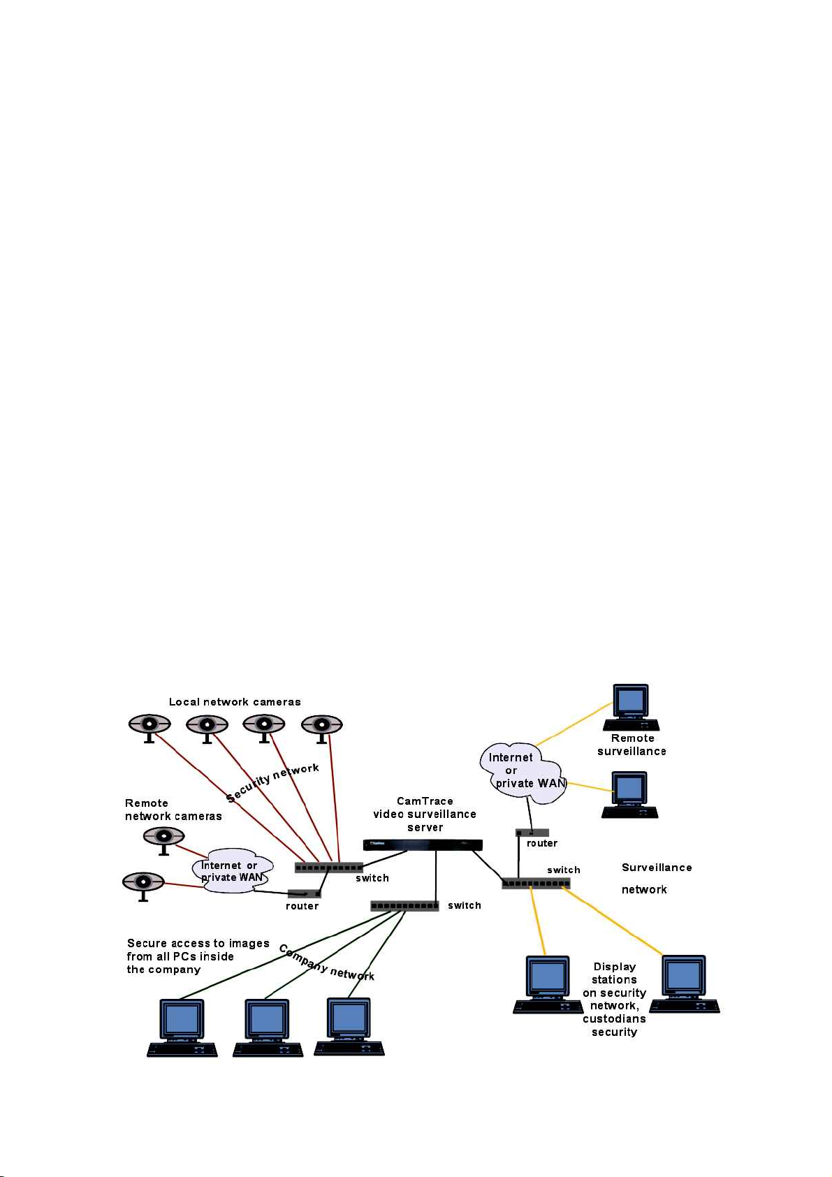
Note: CamTrace has one or more network cards (usually two): You can mix cameras and
display stations on all networks at will. But we recommend that you create ‘specialist’
networks, particularly for important setups. In this way, you can group cameras on one or
more security networks, use another network interface to connect to the company’s network
and yet another to connect to a display network (guard houses and display PCs).
7
CamTrace installation overview

This separation of the network optimizes the performance and the security of your video
installation. When several CamTraces are used we strongly advise you to isolate the cameras
attached to each CamTrace on different networks.
For small configurations it is possible to use a single network card.
We recommend a Gigabit link between CamTrace and the switches. If the network
contains more than ten cameras, the Gigabit link is necessary to obtain fluid images
in 640 x 480 or higher formats.
1.2 IP CONFIGURATION OF CAMTRACE SERVER
1.2.1 Default adresses
CamTrace has one or more (usually two) Ethernet network interfaces, RJ45 ports,
labeled by the name they have in the operating system.
For example : em0, em1, bge0, bge1, reo0, reo1, etc.
Two of these network interfaces have a default address. If there are more than two,
additional interfaces do not have a default address.
First default address: 192.168.1.100
Second default address: 192.168.0.100
Careful: there is no default address when CamTrace is delivered as software.
Network topology using the default addresses (example)
8

1.2.2 Data collection for connection to an existing network
If you must connect the CamTrace video server to an existing company network, you
will need the following information:
• An IP address for your CamTrace server on the company network side.
• The network mask.
• A network name for the CamTrace server. The "network name" is the name that
you give to the CamTrace server on the local network. If the company has a DNS,
we recommend that its name be consistent with that given to the CamTrace in
this DNS.
• The IP address of an internal or external DNS. This parameter is optional. It is used
by the CamTrace server to reach external names with their names (FQDN) and
not only their IP addresses (for example, mail server)
• The IP address of the default gateway: This parameter is optional. It is required to
reach the CamTrace server from a client workstation located outside the segment
on which the CamTrace server is located. For example, to access a CamTrace
via the Internet, you must enter the IP address of your router on the local network
side (LAN). It is also used by CamTrace to "exit" the address class of the local
network (for example, connection to an NTP time server, or to an email server).
1.2.3 General information about the CamTrace network settings
Pour configurer les paramètres réseau depuis menucam, il existe deux méthodes,
● You can configure CamTrace manually with menucam.
● You can use the installation wizard that allows you to define the network and
system settings by answering key questions.
Caution : If the address class of the name server (DNS) is different from those used on the
CamTrace networks, the gateway must be filled in.
Caution: You must assign two addresses to CamTrace belonging to different networks. To
avoid serious malfunction of your CamTrace network, you must never use the same address
class on both interfaces.
Examples of CamTrace addresses:
Camera side Company side
192.168.0.111 192.168.0.112 incorrect
192.168.0.111 192.168.1.112 good
192.168.0.111 192.168.1.111 good
Note : If you use CamTrace on a single network, be sure to leave blank the values defined for
the other networks. In "Network configuration / Network interface configuration" leave blank
(or delete) the fields corresponding to the unused network interface
1.2.4 Manually set the network parameters
Open an administrator’s session: login "root" password "camtrace".
Enter "menucam" then press Enter.
The following screen appears:
9
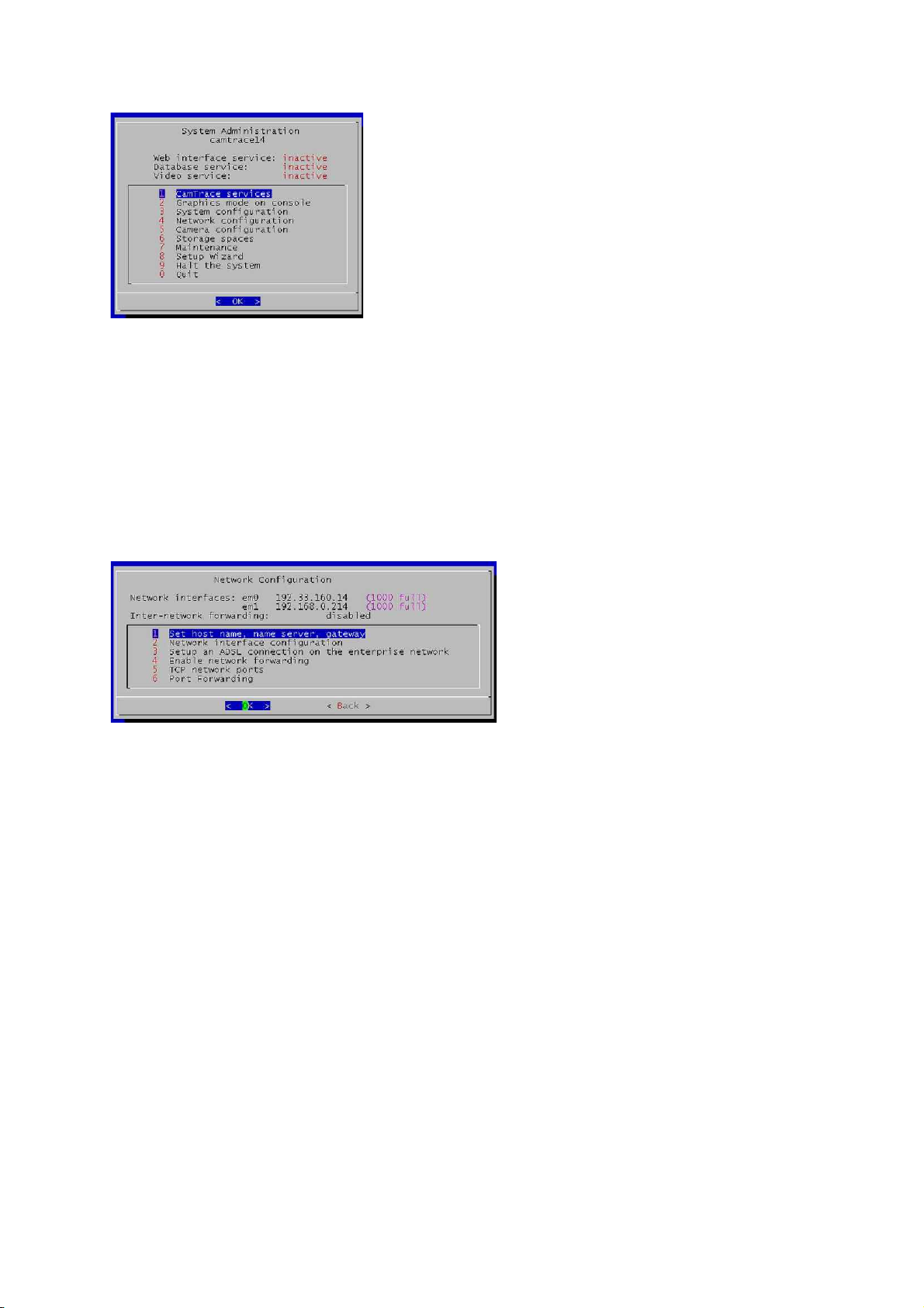
Go to the menu "Network configuration". In the
submenu "Network interface configuration" enter the
IP address, mask values and leave empty the
maximum bandwidth state.
Then in "Set host name, name server, gateway"
enter the values obtained above.
In the "Set host name, name server, gateway"
submenu, the "IP address of the Name server" field, can be filled as follows :
- Leave the field empty.
- Type the IP address of the internal DNS if it exists.
- Type the DNS IP address of the company Internet service provider.
Attention : If you are not sure of the DNS address, leave this field empty. An incorrect value will
slow CamTrace down considerably.
Once you have entered the required information, the IP addresses and the
connection status (100 full or 1000 full) appear in the upper part of the "Network
configuration" menu.
To test the configuration, go to the "Quit" menu and perform a ping on the IP address
of a local network station :
# ping station_IP_address enter
To stop the ping, enter CTRL C
Note : CamTrace cannot "ping" a host with its Netbios name (the one that appears in the
Microsoft neighborhood network).
The CamTrace server does not appear in the network neighborhood of Microsoft client
workstations.
1.2.5 Adjusting system parameters
With Menucam, you can adjust a number of parameters required for correct server
operation. In particular, with the "System configuration" menu you can set the
CamTrace time zone and time.
You must first be in the right time zone. Choose the continent and the country in
which you are located.
CamTrace automatically manages daylight saving times. Simply enter the local time
in the "Set the date and time" menu.
10

1.2.6 Using the setup wizard
The setup wizard will guide you step by step during installation. If you are not familiar
with CamTrace, it will prevent you from forgetting an important step.
In menucam , choose the
setup wizard - choice 8 -
The setup wizard lets you
choose respectively :
- the menus language
- the console keyboard language
- the server's time zone
- IP addresses and masks of the network interfaces available on the server
The setup wizard then lets you choose optional parameters :
- the server name on the network
- the domaine name server (DNS) address
- The address of the gateway
- the maximum bandwidth allowed through the gateway
- the address of a time server (NTP)
1.3 CAMERA CONFIGURATION
1.3.1 Configuring the IP address of each camera
Each camera must have a fixed IP address on the network. For historical stability
reasons for addressing, CamTrace is not a DHCP server.
Attention You must always define the IP address of a camera and check its operations before
placing it in an area difficult to access (pole, housing, etc.).
There are two methods for defining the IP address for each camera.
a) Configuration offered by the camera manufacturer.
This is the standard configuration valid for all camera brands.
Configuration software is always provided with the cameras: IP Utility - IP Finder, IP
setup, etc, depending on the manufacturer.
Install the utility on a PC connected to the network on which the cameras are found.
Most utilities automatically detect the network cameras. You need only provide the
IP address and occasionally other parameters depending on the manufacturer.
b) Configuration using the
CamTrace server.
In menucam, choose "Camera
configuration" and then "Set
the network address of a
camera".
11
The program asks you to enter the MAC address of the camera (this address is
marked on the camera), then the IP address that you wish to assign to it. When you
enter the MAC address, separate each group of two characters with ":".
Switch off the power supply to your camera and then turn it back on.
To check the network connection for the camera that you have installed, you can
perform a "ping" on the allocated address, from the CamTrace server (on the
console or from a remote terminal). To do so, exit the menucam and enter:
#ping camera_adress enter
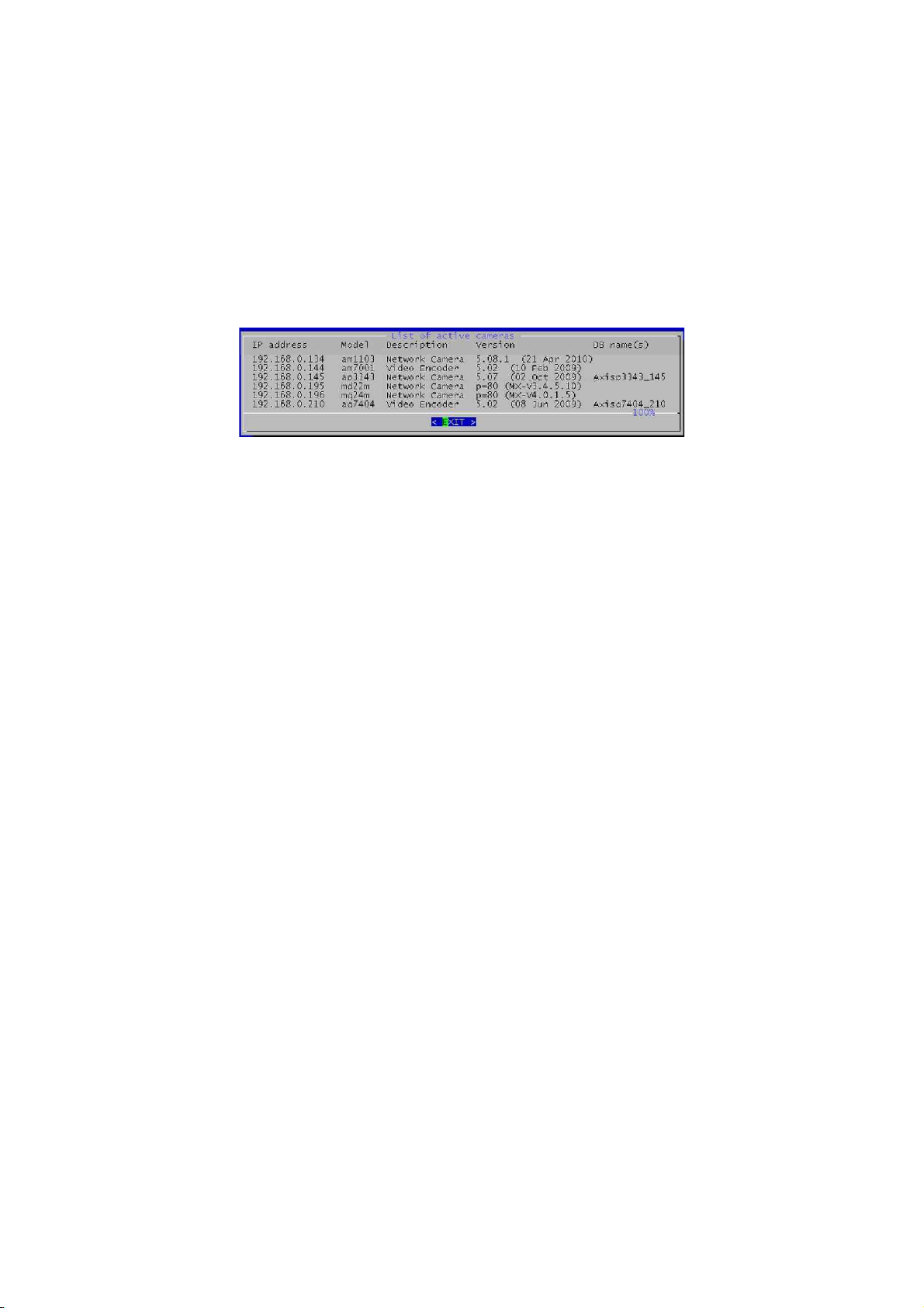
List of active cameras
Note : sub-menu 1 "list active cameras" indicates the list of cameras recognized as active (IP,
model, description, version, name). This function may not work for certain camera models.
1.3.2 Camera configuration
Each camera model has its own configuration. Refer to the manufacturer’s
documentation.
To test the camera that you are installing, check that you have an animated image
that appears in the browser using a PC connected to the same network as this
camera.
You can fine-tune configuration and image quality at this point or after declaring the
camera in CamTrace.
1.3.2.1 Checklist of operations to be performed on each camera
- Give a fixed IP address to the camera. Check that DHCP is not active.
- Fill in the network mask.
- Enter the administrative logins and passwords for the camera (certain cameras
have default passwords, others must be entered).
- In the video settings, configure the camera in mjpeg mode (to start).
From CamTrace V x.10.x it is possible to capture a video stream in MPEG4 or H264
Specific settings of these modes are explained in the administration manual.
- Enter the gateway address that is the address of the CamTrace on the network
where the camera is to be connected.
- Enter the address of the NTP server that is the same as the previous address.
- Display the time in the image (recommended).
- Set the time zone and adaptation to winter/summer times.
- Limit the bandwidth of the camera to that which is necessary.
- Settings concerning image quality, obturation speed, compression, image size,
lighting type, backlighting, etc. can be provided at a later date.
12
 Loading...