

Page 1
8-Sp
Modelo IFN10400
Manual de Instrucciones
tection equipment, and when
required, other appropriate protection equipment such as head, hearing and foot protection equipment.
Serious eye or permanent hearing
loss could result.
• Assuring that the tool is kept in
safe working order as described in
this manual.
• Assuring the proper maintenance
of all tools in employer’s possession.
• Ensuring that tools which require
repair are not further used before
repair. Tags and physical segregation are recommended means of
control.
Table of Contents
General Safety . . . . . . . . . . . . .1-3
Specifications . . . . . . . . . . . . . . .2
Operating The Tool . . . . . . . . .3-5
Troubleshooting . . . . . . . . . . . . .7
Warranty . . . . . . . . . . . . . . . . . . .8
Description
This tool is designed for decorative
trim, molding, window casings, furniture trim, picture frame assembly, cabinetry, casebacks, and crafts. Features
include: convenient top loading magazine which holds up to 100 brads or
staples, adjustable depth control,
adjustable exhaust, quick clear nose.
General Safety
Information
CALIFORNIA PROPOSITION 65
You
can
create dust when you cut,
sand, drill or grind materials such as wood, paint,
metal, concrete, cement, or
other masonry. This dust often contains
chemicals known to cause cancer, birth
defects, or other reproductive harm.
Wear protective gear.
This product or its power cord contains
chemicals known to the State of
California to cause cancer and birth
defects or other reproductive harm.
Wash hands after handling.
This manual contains safety, operational and maintenance information.
!
WARNING
!
DANGER
Contact your Campbell Hausfeld representative if you have any questions.
OPERATOR’S RESPONSIBILITY:
The tool operator is responsible for:
• Reading and understanding tool
labels and manual.
• Selecting an appropriate tool actuation system, taking into consideration the work application for which
the tool is used.
• The safe use of the
tool.
• Ensuring that the
tool is used only
when the operator and all other
personnel in the work area are
wearing ANSI Z87 eye protection
equipment, and when required,
other appropriate protection equipment such as head, hearing and
foot protection equipment. Serious
eye or permanent hearing loss
could result.
• Assuring that the tool is kept in safe
working order as described in this
manual.
EMPLOYER’S RESPONSIBILITY:
• Selecting an appropriate tool actuation system, taking into consideration the work application for which
the tool is used.
• Ensuring that this manual is available to operators and personnel
performing maintenance.
• The safe use of the
tool.
• Enforcing that the
tool is used only when the operator
and all other personnel in the work
area are wearing ANSI Z87 eye pro-
Operating Instructions Model IFN10400
2-in-1
Nailer/Stapler
Please read and save these instructions. Read carefully before attempting to assemble, install, operate or maintain the product described.
Protect yourself and others by observing all safety information. Failure to comply with instructions could result in personal injury, death and/or
property damage! Retain instructions for future reference.
Model IFN10400
IN705500AV 8/05
Iron Force Nailers meet or exceed Industries’
Standards as set forth by the American
National Standard Institute/International
Staple, Nail and Tool Association in ANSI/ISANTA SNT-101-2002.
© 2005
See Warranty on page 8 for important information about commercial use of this product.
REMINDER: Keep your dated proof of purchase for warranty purposes! Attach it to this manual or file it for safekeeping.
For parts, product & service information
visit www.chpower.com
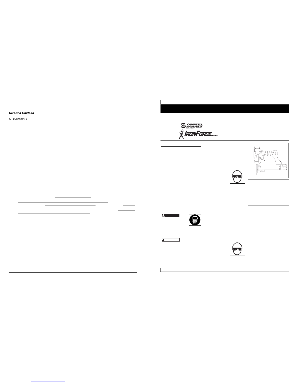
Locate model and date code on tool
magazine and under nozzle shield,
and record below:
Model No. ________________________
Date Code ________________
Retain these numbers for
future reference.
;;;;;;
;;;;;;
;;;;;;
;;;;;;
Garantía Limitada
1. DURACIÓN: Desde la fecha de compra por parte del comprador original, según se detalla: Campbell Hausfeld (Trabajo
estándar y sin especificar) – 1 (un) año, (Trabajo pesado) – 2 (dos) años, (Trabajo extremo) – 3 (tres) años; IronForce de
Campbell Hausfeld – 1 (un) año; Farmhand – 3 (tres) años; Maxus – 5 (cinco) años.
2. QUIEN OTORGA ESTA GARANTIA (EL GARANTE: Campbell Hausfeld / The Scott Fetzer Company 100 Production Drive,
Harrison, Ohio 45030 Teléfono: (800) 543-6400
3. QUIEN RECIBE ESTA GARANTIA (EL COMPRADOR): El comprador original (que no sea un revendedor) del producto
Campbell Hausfeld.
4. PRODUCTOS CUBIERTOS POR ESTA GARANTIA: Cualquier clavadora, grapadora, herramienta neumática, pistola pulverizadora, inflador o accesorio neumático suministrado o fabricado por el Garante.
5. COBERTURA DE LA GARANTIA: Los defectos substanciales de material y fabricación que ocurran dentro del período de
validez de la garantía.
6. LO QUE NO ESTA CUBIERTO POR ESTA GARANTIA:
A. Las garantías implícitas, incluyendo aquellas de comercialidad E IDONEIDAD PARA FINES PARTICULARES, ESTAN
LIMITADOS A LO ESPECIFICADO EN EL PARRAFO DE DURACION. Si este producto es empleado para uso comercial,
industrial o para renta, la garantía será aplicable por noventa (90) días a partir de la fecha de compra. En algunos
estados no se permiten limitaciones a la duración de las garantías implícitas, por lo tanto, en tales casos esta limitación no es aplicable.
B. CUALQUIER PERDIDA DAÑO INCIDENTAL, INDIRECTO O CONSECUENTE QUE PUEDA RESULTAR DE UN DEFECTO,
FALLA O MALFUNCIONAMIENTO DEL PRODUCTO CAMPBELL HAUSFELD. En algunos estados no se permite la
exclusión o limitación de daños incidentales o consecuentes, por lo tanto, en tales casos esta limitación o exclusión
no es aplicable
C. Cualquier falla que resulte de un accidente, abuso, negligencia o incumplimiento de las instrucciones de fun-
cionamiento y uso indicadas en el (los) manual(es) que se adjunta(n) al producto. Dichos accidentes, abusos por
parte del comprador, o falta de operar el producto siguiendo las instrucciones del manual de instrucciones suministrado también debe incluir la desconexión o modificación de los instrumentos de seguridad. Si dichos instrumen-
tos de seguridad son desconectados, la garantía quedaría cancelada.
D. Los ajustes normales explicados en el(los) manual(es) suministrado(s) con el producto.
E. Artículos o servicios normalmente requeridos para el mantenimiento del producto, tales como: anillos en O,
resortes, amortiguadores, defensas, hojas de impulsor, fusibles, baterías
, empaques, almohadillas o sellos, boquillas
de fluído, agujas, boquillas para rociar arena, lubricantes
, mangueras de material, elementos filtrantes, álabes de
motores, abrasivos, hojillas, discos para cortar, cinceles, retenes para cinceles, cortadores, collarines, mandriles, mordazas para remachadoras, brocas para desarmadores, almohadillas para lijar
, soportes de almohadillas, mecanismo
de impacto
o cualquier otro artículo desgastable que no se haya enumerado específicamente . Estos artículos sólo
estarán cubiertos bajo esta garantía por noventa (90) días a partir de la fecha de compra original. Los artículos sub
-
rayados sólo están garantizados por defectos de material o fabricación.
F. Defectos estéticos que no interfieran con la función del producto
7. RESPONSABILIDADES DEL GARANTE BAJO ESTA GARANTIA: Reparar o reemplazar, como lo decida el Garante, los productos o componentes que estén defectuosos, se hayan dañado o hayan dejado de funcionar adecuadamente, durante
el período de validez de la garantía
8. RESPONSABILIDADES DEL COMPRADOR BAJO ESTA GARANTIA:
A. Suministrar prueba fechada de compra y la historia de mantenimiento del producto.
B. Entregar o enviar el producto o componente Campbell Hausfeld al Centro de Servicio autorizado Campbell Hausfeld
más cercano. Los gastos de flete, de haberlos, deben ser pagados por el comprador.
C. Seguir las instrucciones sobre operación y mantenimiento del producto, tal como se indica(n) en el (los) manual(es)
del propietario
9. CUANDO EFECTUARA EL GARANTE LA REPARACION O REEMPLAZO CUBIERTO BAJO ESTA GARANTIA: La reparación o
reemplazo dependerá del flujo normal de trabajo del centro de servicio y de la disponibilidad de repuestos.
Esta garantía limitada es válida sólo en los EE.UU., Canadá y México y otorga derechos legales específicos. Usted también
puede tener otros derechos que varían de un Estado a otro. o de un país a otro.
Page 2

Los anillos en O de la cubierta de la válvula
del gatillo están dañados
Los tornillos de la cubierta están flojos
Los anillos en O están dañados
La cubierta está dañada
Los tornillos están flojos
El empaque está dañado
La cubierta está desgastada
La boquilla está sucia
La suciedad o daños evitan el
desplazamiento libre de los sujetadores o
el mecanismo de impulso en el cargador
El resorte del mecanismo de impulso está
dañado
El flujo de aire hacia la herramienta es
inadecuado
El anillo en O del pistón está desgastado o le
falta lubricación
Los anillos en O de la válvula del gatillo
están dañados
Hay fugas de aire
Hay una fuga en el empaque de la tapa
La herramienta no está bien lubricada
El resorte de la tapa del cilindro está roto
El orificio de salida de la tapa está obstruído
La guía del mecanismo de impulso está
desgastada
Los sujetadores no son del tamaño adecuado.
Los sujetadores están doblados
Los tornillos del cargador o de la boquilla están
flojos
El mecanismo de impulso está dañado
Hay una fuga de aire en el
área de la válvula del gatillo
Hay una fuga de aire entre
la cubierta y la boquilla
Hay una fuga de aire entre
la cubierta y la tapa
La herramienta deja de
clavar un sujetador
La herramienta funciona
lentamente o pierde su
potencia
Hay sujetadores atascados
en la herramienta
Debe reemplazar los anillos en O y chequear el funcio-
namiento del elemento de funcionamiento al contacto
Debe apretar los tornillos
Debe reemplazar los anillos en O
Debe reemplazar la defensa
Debe apretar los tornillos
Debe reemplazar el empaque
Debe reemplazar la cubierta
Debe limpiar el canal del sistema de impulso
Debe limpiar el cargador
Debe reemplazar el resorte
Cheque las conexiones, la manguera o el compresor
Debe reemplazar los anillos en O. Lubríquelos.
Debe reemplazar los anillos en O
Debe apretar los tornillos y las conexiones
Debe reemplazar el empaque
Necesita lubricar la herramienta
Debe reemplazar el resorte
Debe reemplazar las partes internas dañadas
Debe reemplazar la guía
Debe usar los sujetadores recomendados para esta
herramienta
Reemplácelos con sujetadores en buenas condiciones
Debe apretar los tornillos
Debe reemplazar el mecanismo de impulso de sujetadores
7-Sp
Manual de Instrucciones
Modelo IFN10400
Guía de Diagnóstico de Averías
Deje de usar la herramienta inmediatamente si alguno de los siguientes problemas ocurre.
Podría resultar en heridas graves. Cualquier reparación o reemplazo de piezas los debe hacer un
técnico calificado de servicio o un centro autorizado de servicio.
!
ADVERTENCIA
Problema Causa Solución
2
General Safety
Information (Continued)
Danger indicates
an imminently hazardous situation which, if not avoided,
WILL result in death or serious injury.
Read and understand
tool labels and manual.
Failure to follow warnings, dangers, and cautions could result in
DEATH or SERIOUS
INJURY.
Do not use any type
of reactive gases,
including, but not limited to, oxygen and
combustible gases, as
a power source. Use
filtered, lubricated,
regulated compressed air only. Use
of a reactive gas instead of compressed air may cause the tool to
explode which will cause death or
serious personal injury.
Use only a pressure-
regulated compressed
air source to limit the
air pressure supplied
to the tool. The regulated pressure must
not exceed 100 psi. If the regulator
fails, the pressure delivered to the
tool must not exceed 200 psi. The
tool could explode which will cause
death or serious personal injury.
Never use gasoline
or other flammable
liquids to clean the
tool. Never use the
!
DANGER
tool in the presence of flammable
liquids or gases. Vapors could ignite
by a spark and cause an explosion
which will result in death or serious
personal injury.
Always remain in
a firmly balanced
position when
using or handling
the tool.
Do not remove,
tamper with, or
otherwise cause
the Work Contact
Element (WCE) or
trigger to become
inoperable. Do
not operate any tool which has been
modified in a like fashion. Death or
serious personal injury could result.
Do not touch the
trigger unless driving fasteners.
Never attach air
line to tool or
carry tool while
touching the trigger. The tool could eject a fastener
which will result in death or serious
personal injury.
Warning indicates
a potentially
hazardous situation which, if not avoided, COULD result in death or
serious injury.
Always discon-
nect the tool
from the power
source when
unattended,
!
WARNING
performing any maintenance or
repair, clearing a jam, or moving the
tool to a new location. Always
reconnect the air line BEFORE loading any fasteners. Do not load the
tool with fasteners when either the
trigger is depressed or the Work
Contact Element (WCE) is engaged.
The tool could eject a fastener causing death or serious personal injury.
Always fit tool
with a fitting
or hose coupling on or
near the tool in
such a manner
that all compressed air in the tool is discharged
at the time the fitting or hose coupling is disconnected. Do not use a
check valve or any other fitting which
allows air to remain in the tool. Death
or serious personal injury could occur.
Never place hands or
any other body parts in
the fastener discharge
area of the tool. The
tool might eject a fastener and could result
in death or serious personal injury.
Never carry the
tool by the air
hose or pull the
hose to move the
tool or a compressor. Keep hoses
away from heat,
oil and sharp edges. Replace any
hose that is damaged, weak or
worn. Personal injury or tool damage could occur.
Model IFN10400
Operating Instructions
• REQUIRES: 0.8 SCFM with 10 fasteners per minute @ 90 psi
• AIR INLET: 1/4” NPT
• FASTENER SIZE RANGE: 3/8” to
1 1/4”
• MAGAZINE CAPACITY:
100 fasteners per load, 18 gauge
• STAPLES: 1/4” crown
• WEIGHT: 2 lbs., 15 oz.
• LENGTH: 10 1/2”
• HEIGHT: 9 1/2”
• MAXIMUM PRESSURE: 100 psi
• PRESSURE RANGE: 60 - 100 psi
Tool Components And Specifications
www.chpower.com
Cap exhaust
O
CO
2
100 psi
MAX.
Warning label
Latch button
Magazine
Fastener discharge area
Work contact element (WCE)
Trigger
Quick clear nose
Adjustable depth control
(not visible)
Page 3

1
1
MPA
bar
psi
1
1
7
.
.
.
.
5
9
1
6
8
1
1
3
4
1
6-Sp
Manual de Instrucciones
Modelo IFN10400
3
General Safety
Information (Continued)
Always assume the tool contains
fasteners. Respect the tool as a
working implement; no horseplay.
Always keep others at a safe distance from the work area in case of
accidental discharge of fasteners.
Do not point the tool toward yourself or anyone whether it contains
fasteners or not. Accidental triggering of the tool could result in death
or serious personal injury.
Do not drive a fas-
tener on top of
other fasteners.
The fastener could
glance and cause
death or a serious
puncture wound.
Do not operate
or allow anyone
else to operate
the tool if any
warnings or
warning labels
are not legible. Warnings or warning
labels are located on the tool magazine and body.
Do not drop or throw the tool.
Dropping or throwing the tool can
result in damage that will make the
tool unusable or unsafe. If the tool
has been dropped or thrown, examine the tool closely for bent, cracked
or broken parts and air leaks. STOP
and repair before using or serious
injury could occur.
Caution indicates
a potentially hazardous situation which, if not avoided,
MAY result in minor or moderate
injury.
Do not make any modifications to the
tool without first obtaining written
!
CAUTION
Standard B19.3-1991; Safety
Standard for Compressors for
Process Industries. Contact your air
compressor manufacturer for
information.
Operating The Tool
RECOMMENDED HOOKUP
The illustration below shows the
recommended hookup for the tool.
1. The air compressor must be able to
maintain a minimum of 60 psi
when the tool
is being used.
An inadequate
air supply can
cause a loss of
power and inconsistent driving.
2. Use 3/8” air hoses with a minimum
working pressure of 150
psi. Use 1/2”
air hoses for
50’ run or
longer. For better performance,
install a 3/8” quick plug (1/4” NPT
threads) with an inside diameter of
.315" (8mm) on the tool and a 3/8”
quick coupler on the air hose.
3. Use a pressure regulator on the
compressor, with
an operating
pressure of 0 -125
psi. A pressure
regulator is
required to control the operating
pressure of the tool between 60
and 100 psi.
approval from Campbell Hausfeld. Do
not use the tool if any shields or
guards are removed or altered. Do
not use the tool as a hammer.
Personal injury or tool
damage may occur.
Avoid long extended periods of
work with the tool. Stop using the
tool if you feel pain in hands or
arms.
Always check that the Work Contact
Element (WCE)
is operating
properly. A fastener could accidentally be driven if the WCE
is not working
properly.
Personal injury
may occur (See "Checking the Work
Contact Element" Section).
Disconnect air supply and release
tension from the pusher before
attempting to clear jams because
fasteners can be ejected from the
front of the tool. Personal injury
may occur.
Notice indicates
important infor-
mation, that if not followed, MAY
cause damage to equipment.
Avoid using the tool when the mag-
azine is empty. Accelerated wear on
the tool may occur.
Clean and check all air supply hoses
and fittings before connecting the
tool to an air supply. Replace any
damaged or worn hoses or fittings.
Tool performance or durability may
be reduced.
Air compressors providing air to the
tool should follow the requirements
established by the American
National Standards Institute
NOTICE
Model IFN10400
Operating Instructions
www.chpower.com
!
WARNING
Recommended Hookup
Quick
Plug
Quick
Coupler
Air
Hose
Quick Plug
(Optional)
Quick
Coupler
(Optional)
Regulator
Filter
Calibre Clavos por Clavos por
Modelo # Longitud
del cuerpo
Acabado Cabeza Unión
línea Caja
aFB001600 15,9mm (5/8”) Calibre 18 Galvanizado De puntilla/Café Adhesivo 100 5000
FB002000 19,1mm (3/4”) Calibre 18 Galvanizado De puntilla/Café Adhesivo 100 5000
FB002500 25,4mm (1”) Calibre 18 Galvanizado De puntilla/Café Adhesivo 100 5000
FB003000 31,8mm (1
1
⁄
4”) Calibre 18 Galvanizado De puntilla/Café Adhesivo 100 5000
FB180016 15,9mm (5/8”) Calibre 18 Galvanizado De puntilla/Café Adhesivo 100 1000
FB180025 25,4mm (1”) Calibre 18 Galvanizado De puntilla/Café Adhesivo 100 1000
FB180030 31,8mm (1
1
⁄
4”) Calibre 18 Galvanizado De puntilla/Café Adhesivo 100 1000
Clavos
Estos clavos para acabado de Campbell Hausfeld los puede comprar en su tienda más cercana. Si necesita ayuda para encontrar
un artículo, comuníquese al 1-800-543-6400. Los clavos de Campbell Hausfeld cumplen o exceden el estándar ASTM F1667
Información de intercambio
IFN10400 can use 3/8” to 1-1/4” 18 gauge brad nails designed for the following tools:
• Bostitch
®
BT125SK-2 • Campbell Hausfeld® NB0030
• DeWalt
®
D51238K • Hitachi® NT32AE
• Paslode
®
T125-F18 • Porter Cable®BN125
• Senco
®
Finish Pro™ 15
Grapas
Estas grapas para acabado de Campbell Hausfeld los puede comprar en su tienda más cercana. Si necesita ayuda para encontrar un artículo, comuníquese al 1-800-543-6400. Las grapas de Campbell Hausfeld cumplen o exceden las especificaciones
Federales FF-N-105B.
Información de intercambio
IFN10400 can use 3/8” to 1-1/4” 18 gauge, 1/4” crown staples designed for the following tools:
• Campbell Hausfeld
®
SN258K • Hitachi® N3804AB
• Porter Cable
®
NS100, NS150 • Senco®SLS15, SLS18, SLS25XP
Calibre Fusión de Grapas Grapas
Modelo # Longitud de la grapa Corona Punta Acabado la linea por linea por caja
FN158K00 12,7mm (1/2”) Calibre 18 6,4mm(1/4") Cincel Galvanizado/Cubierta por vinilo Adhesivo 100 5000
FN168K00 15,9mm (5/8”) Calibre 18 6,4mm(1/4") Cincel Galvanizado/Cubierta por vinilo Adhesivo 100 5000
FN180615 12,7mm (1/2”) Calibre 18 6,4mm(1/4") Cincel Galvanizado/Cubierta por vinilo Adhesivo 100 1000
FN180620 19,1mm (3/4”) Calibre 18 6,4mm(1/4") Cincel Galvanizado/Cubierta por vinilo Adhesivo 100 1000
FN180625 25,4mm (1”) Calibre 18 6,4mm(1/4") Cincel Galvanizado/Cubierta por vinilo Adhesivo 100 1000
FN180630 31,8mm (1
1
⁄
4”) Calibre 18 6,4mm(1/4") Cincel Galvanizado/Cubierta por vinilo Adhesivo 100 1000
FN208K00 19,1mm (3/4”) Calibre 18 6,4mm(1/4") Cincel Galvanizado/Cubierta por vinilo Adhesivo 100 5000
FN258K00 25,4mm (1/4”) Calibre 18 6,4mm(1/4") Cincel Galvanizado/Cubierta por vinilo Adhesivo 100 5000
Sujetadores
60 psi
Min.
100 psi
Max.
150 PSI WP
3/8” I.D.
Page 4
SINGLE SEQUENTIAL MODE
This mode
requires the trigger to be pulled
each time a fastener is driven.
The tool can be actuated by depressing
the WCE against the work surface followed by pulling the trigger.
The trigger must be released to reset
the tool before another fastener can
be driven.
CHECKING THE WORK CONTACT
ELEMENT (WCE)
Check the opera-
tion of the Work
Contact Element (WCE) trip mechanism
before each use. The WCE must move
freely without binding through its
entire travel distance. The WCE spring
must return the WCE to its fully extended position after being depressed. Do
not operate the tool if the WCE trip
mechanism is not operating properly.
Personal injury may occur.
1. Disconnect the
air supply from
the tool.
2. Remove all fas-
teners from the
magazine (see
Loading/
Unloading).
3. Make sure the trig-
ger and work contact element (WCE)
move freely up and
down without sticking or binding.
4. Reconnect air
supply to the
tool.
5. Depress the Work
Contact Element
(WCE) against the
work surface with-
!
CAUTION
PARA AJUSTAR LA PENETRACION DE
LOS SUJETADORES
La CHN104 viene equipada con un
mecanismo clavador de profundidad
ajustable. Esto le permite al usuario
determinar a qué profundidad se va a
clavar en la superficie de trabajo.
1. Ajuste la presión de operación a
aquella que usará con regularidad
para clavar los sujetadores. No exceda
la presión de 6,90 bar.
2. Para dirigir la herramienta, gire la
rueda (C) hacia la derecha hasta el
punto deseado.
3. Para clavar el sujetador más profundo, gire la rueda (C) hacia la izquierda hasta el punto deseado.
4. Asegúrese que el
gatillo y el Elemento
de Contacto de
Trabajo se mueven
libremente hacia
arriba y hacia abajo sin atascarse o
pegarse después de cada ajuste.
PARA AJUSTAR LA DIRECCION DEL
TUBO DE ESCAPE
El modelo
IFN10400 está
equipado con un
deflector
ajustable de la
dirección del tubo
de escape. Éste le permite al usuario
cambiar la dirección del tubo de
escape. Simplemente mueva el deflector hacia la dirección deseada.
QUÉ HACER CUANDO LA HERRAMIENTA TENGA UN SUJETADOR
ATASCADO
1. Desconecte la
herramienta de
la fuente de
suministro de
aire.
2. Remueva todos
los sujetadores
del depósito
(vea Carga /
Descarga).
Si no se
retiran
todos los sujetadores éstos saldrán por el
frente de la herramienta.
3. Destrabe el gan-
cho presionando
el botón en el
lado del cargador. El botón
destrabará el gancho de la boquilla.
4. Ahora se puede
girar la puerta,
dejando al descubierto el sujetador que esté trabado.
5. Retire todos
los sujetadores que
estén trabados, utilizando unas pinzas o un destornillador
si fuera necesario.
6 Vuelva a girar la
puerta a su posición de cerrado.
7. Vuelva a presion-
ar el botón para
levantar el gancho. Cierre la
puerta y suelte el
botón para volver
a trabar el gancho con la boquilla.
!
ADVERTENCIA
Cómo usar la
Herramienta (Cont.)
8. Asegúrese de que el
gatillo y el elemento
de contacto de trabajo (WCE) se muevan libremente hacia
arriba y hacia abajo sin adherirse ni
trabarse.
Servicio Técnico
Si desea hacer alguna pregunta referente a la reparación u operación de las
herramientas, o para solicitar copias
adicionales de este manual, sírvase llamar a nuestro número especial, 1-800543-6400.
Sujetadores y Piezas de
Repuesto
Use solamente sujetadores Campbell
Hausfeld originales calibre 16 (o su
equivalente) - (vea la información sobre
intercambio de sujetadores). El
desempeño de las herramientas, la
seguridad y la duración pueden
disminuir si no se utilizan los
sujetadores adecuados. Cuando ordene
piezas de repuesto o sujetadores,
especifique el número de la pieza.
Para reparar la herramienta
La herramienta debe ser reparada únicamente por personal calificado, y
deben usar piezas de repuesto y accesorios originales Campbell Hausfeld, o
piezas y accesorios que funcionen de
manera equivalente.
Para colocarle los sellos
Cada vez que repare una herramienta
deberá limpiarle y lubricarle las partes
internas. Le recomendamos que use
Parker O-lube o un lubricante equivalente en todos los anillos en O. A cada
anillo en O se le debe dar un baño de
lubricante para anillos antes de instalarlos. Igualmente, deberá ponerle un
poco de aceite a todas las piezas que se
mueven y muñones. Finalmente,
después de haberla ensamblado y antes
de probar la herramienta deberá
ponerle unas cuantas gotas de aceite
sin detergente 30W u otro aceite similar, en las líneas de aire.
!
ADVERTENCIA
Modelo IFN10400
5-Sp
Manual de Instrucciones
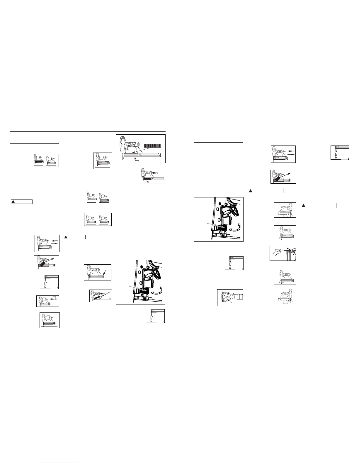
4. Push the magazine cover forward until
latch button
pops up.
5. Always unload
all fasteners before removing tool
from service. Unloading is the
reverse of loading, except that you
must disconnect the air supply
before unloading.
ADJUSTING THE FASTENER PENETRATION
The tool is equipped with an adjustable
depth of drive feature. This allows the
user to determine how deep a fastener
will be driven into the work surface.
1. Adjust operating pressure so fasteners are driven consistently. Do not
exceed 100 psi.
2. For shallow penetration, turn the
wheel (C) to right to the extent
desired.
3. For deeper penetration, turn the
wheel (C) to left to the extent
desired.
4. Make sure trigger
and work contact
element (WCE)
move freely up and
down without binding or sticking after each adjustment.
out pulling the trigger. The tool
MUST NOT OPERATE. Do not use
the tool if it operates without
pulling the trigger. Personal injury
may result.
6. Remove the tool
from the work surface. The Work
Contact Element
(WCE) must return
to its original down
position. The tool MUST NOT
OPERATE. Do not use the tool if it
operates while lifted from the work
surface. Personal injury may result.
7. Pull the trigger and depress the
work contact
element
(WCE)
against the
work surface.
The tool MUST NOT OPERATE.
8. Depress the Work Contact Element
(WCE)
against the
work surface.
Pull the trigger. The tool
MUST OPERATE.
An improperly
functioning tool
must not be used. Do not actuate the
tool unless the tool is placed firmly
against the work piece.
LOADING/UNLOADING THE TOOL
1. Always connect the tool to the air
supply before loading fasteners.
2. Push down
on the latch
button. Pull
back on the
magazine
cover.
3a. For nails, insert a stick of Campbell
Hausfeld nails or
equivalent (see
"Fasteners" section) into the
magazine. Make
sure the pointed ends of the fasteners are resting on the bottom ledge
of the magazine when loading.
Make sure the nails are not dirty or
damaged.
3b. For staples, load a clip of staples
with the crowns straddling the magazine rail.
!
WARNING
Model IFN10400
Operating Instructions
4
www.chpower.com
movement
1
2
1
2
Latch
Button
Magazine rail
Gire
(C)
movemiento
BUILT TO LAST
Operating The Tool
(Continued)
(C)
movement
Cómo usar la
Herramienta (Cont.)
movimiento
Page 5

del elemento de contacto no está funcionando adecudamente. Podría ocasionarle heridas.
1. Desconecte la
herramienta de
la fuente de
suministro de
aire.
2. Saque todos los
sujetadores del
cargador (Vea
la Sección
CargaDescarga).
3. Cerciórese de que el
gatillo y el elemento
de contacto se muevan libremente en
ambos sentidos sin
atascarse o pegarse.
4. Reconecte la her-
ramienta a la
fuente de suministro de aire.
5. Presione el Elemento de Contacto
de Trabajo contra la
superficie de trabajo sin apretar el
gatillo. La herramienta NO DEBE
OPERAR. No use la herramienta si
opera sin apretar el gatillo. Se
pueden producir lesiones personales.
6. Remueva la her-
ramienta de la superficie de trabajo. El
Elemento de
Contacto de Trabajo
tiene que volver a su
posición original. La herramienta
NO DEBE OPERAR. No use la herramienta si opera mientras está levantada de la superficie de trabajo.
7. Apriete el
gatillo y presione el
Elemento de
Contacto de
Trabajo contra la superficie de trabajo. La herramienta NO DEBE hacerse funcionar.
8. Presione el
Elemento de
Contacto de
Trabajo contra la superficie de trabajo. Apriete el gatillo. La
herramienta DEBE OPERAR.
1.
El compresor
de aire debe
tener la
capacidad de
suministrar un
mínimo de
4,14 bar cuando la herramienta esté
en uso. Si el suministro de aire es
inadecuado podría haber pérdida de
potencia y falta de consistencia en el
funcionamiento.
2. Use mangueras de aire de 9,5mm
(3/8”) diseñadas
para presiones
mínimas de
trabajo de 10,34 bar. Use
mangueras de aire de 1/2” si la longitud de las mismas es de 15m ó
más. Para un mejor rendimiento,
instálele a la herramienta un conector rápido de 9,5mm(3/8”) (roscas
de 6,4mm (1/4”) NPT) cuyo
diámetro interno sea de 0,315"
(8mm) y un acoplador rápido de
9,5mm(3/8”) a la manguera de aire.
3. Use un regulador
de presión (de 0
bar-8,27 bar) en el
compresor. Se
necesita un
regulador de presión para controlar
la presión de operación de la herramienta entre 4,14 bar y 6,90 bar.
MODO DE SECUENCIA SINGULAR
Este sistema requiere que oprima el
gatillo cada vez
que vaya a clavar
un sujetador.
Para clavar el
elemento de
contacto debe tocar la superficie de
trabajo y el operador debe oprimir el
gatillo.
Debe soltar el gatillo antes de clavar
otro sujetador.
COMO CHEQUEAR EL ELEMENTO DE
CONTACTO
Cheque
el
funcionamiento del mecanismo del
elemento de contacto antes de cada
uso. El elemento de contacto se debe
desplazar libremente, sin pegarse, a lo
largo del área de desplazamiento. El
resorte del elemento de contacto debe
regresar el elemento de contacto a su
posición original totalmente extendido.
No use la herramienta si el mecanismo
!
PRECAUCION
Modelo IFN10400
Manual de Instrucciones
4-Sp
ADJUSTING THE DIRECTION OF THE
EXHAUST
The IFN10400 is equipped with an
adjustable direction exhaust
deflector. This is
intended to
allow the user to
change the direction of the exhaust. Simply twist the
deflector to any direction desired.
CLEARING A JAM FROM THE TOOL
1. Disconnect the
air supply from
the tool.
2. Remove all fasteners from
the magazine
(see Loading/
Unloading).
Failure to remove
all fasteners will
cause the fasteners to eject from the front
of the tool.
3. Undo hook by
pushing down on
the button on the
side of the magazine. The button
will disengage the hook from the
nose.
4. The door can now
be rotated, exposing the jammed
fastener.
5. Remove the
jammed fastener, using
pliers or a
screwdriver if
required.
!
WARNING
6 Rotate door back
into the closed
position.
7. Push button
down again to
lift the hook.
Close the door
and release
the button to reengage the hook
with the nose.
8. Make sure the trigger and work contact element (WCE)
move freely up and
down without
sticking or binding.
Technical Support
Please call our Tool Hotline at 1-800543-6400 with any questions regarding
the operation or repair of this tool or
for additional copies of this manual.
Fastener And Replacement
Parts
Use only
genuine Campbell
Hausfeld 18 gauge fasteners (or equivalent - see Fastener Interchange
Information). Tool performance, safety
and durability could be reduced if
improper fasteners are used. When
ordering replacement parts or fasteners, specify by part number.
Tool Repair
Only qualified personnel should repair
the tool, and they should use genuine
Campbell Hausfeld replacement parts
and accessories, or parts and accessories
which perform equivalently.
!
WARNING
Assembly Procedure For
Seals
When repairing a tool, the internal
parts must be cleaned and lubricated.
Parker O-lube or equivalent must be
used on all o-rings. Each o-ring must be
coated with O-lube before assembling.
A small amount of oil must be used on
all moving surfaces and pivots. After
reassembling, a few drops of 30W nondetergent oil or equivalent, must be
added through the air line before
testing.
Model IFN10400
Operating Instructions
5
www.chpower.com
Una
herramienta que funciona de manera
inadecuada no debe usarse. No active
la herramienta a menos que esté
colocada firmemente contra la pieza de
trabajo.
PARA CARGAR Y DESCARGAR LA
HERRAMIENTA
1. Siempre conecte la herramienta a
la fuente de suminsitro de aire
antes de colocarle los sujetadores.
2. Empuje hacia
abajo sobre
el boton del
seguro.
Mueva la
tapa del cargador hacia
atrás.
3a. Para clavos,
coloque una serie
de clavos
Campbell Hausfeld
o equi-valentes
(Vea la sección de sujetadores) en el
cargador. Cerciórese de que los
extremos puntiagudos de los clavos
estén hacia la parte inferior del cargador. Cerciórese de que los clavos
no estén sucios ni dañados.
3b. Para grapas, cargue una tira de gra-
pas con las coronas montadas sobre
el riel del cargador.
4. Empuje la tapa
del cargador
hacia delante
hasta que el
botón del
seguro salte
hacia arriba.
5. Siempre descargue el sujetador
antes de remover la herramienta de
servicio. La descarga es lo opuesto a
la carga, excepto que debe
desconectar el suministro de aire
antes de realizar la descarga.
!
ADVERTENCIA
4,14 bar
Min.
6,9 bar
Max.
150 PSI WP
3/8" I.D.
1,27 cm diam. int.
10,34 bar WP
movemiento
1
2
BUILT TO LAST
1
2
Rotate
movement
BUILT TO LAST
Operating The Tool
(Continued)
Cómo usar la
Herramienta (Cont.)
Botón del
seguro
Carril del cargador
Page 6

1
1
MPA
bar
psi
1
1
7
.
.
.
.
5
9
1
6
8
1
1
3
4
1
Informaciones
Generales de Seguridad
(Continuación)
Nunca ponga las manos
ni ninguna otra parte
del cuerpo en el área
de descarga de la
herramienta. Ésta
puede expulsar un sujetador y producir la muerte o lesiones
personales graves.
Nunca cargue la
herramienta por la
manguera de aire ni
jale la manguera para
mover la herra-mienta o el compresor de
aire. Mantenga las
mangueras alejadas del calor, aceite
y objetos puntiagudos. Reemplace
cualquier manguera que esté dañada, débil o desgastada. Ésto podría
ocasionar heridas o daños a la herramienta
Siempre asuma que la herramienta
tiene sujetadores. Respete la
herramienta como un implemento
de trabajo; no jugue con ella.
Siempre mantenga a los demás a
una distancia segura del área de
trabajo, en caso de una descarga
accidental de sujetadores. No
apunte con la herramienta hacia
usted o hacia otra persona, ya sea
que contenga o no sujetadores. El
disparo accidental de la herramienta
podría resultar en la muerte o en
graves lesiones personales.
No clave un suje-
tador encima de
otro. El sujetador
podría saltar y
ocasionarle la
muerte o heridas
graves.
rectamente. Se pueden producir
lesiones personales (vea la sección
“Cómo Revisar el Elemento de
Contacto de Trabajo”).
Desconecte la fuente de suministro
de aire y elimine la tensión del disparador antes de tratar de sacar
cualquier sujetador atascado, ya que
la herramienta podría disparar un
sujetador por el frente. Ésto podría
ocasionarle heridas.
Ésto
le indica
una información importante, que de no
seguirla, le PODRÍA ocasionar daños al
equipo.
Evite usar la herramienta cuando el
depósito está vacío. Ésto podría acelerar su desgaste.
Limpie y chequee todas las
mangueras de suministro de aire y
conexiones antes de conectar la
herramienta al compresor. Reemplace
las mangueras y conexiones que
estén dañadas o desgastadas. El
rendimiento de la herramienta o su
durabilidad podrían reducirse.
Los compresores de aire usados para
suministrarle aire a la herramienta
deben cumplir los requerimientos
establecidos por la organización
norteamericana ANSI en el código
B19.3-1981; sobre seguridad y
estándares para compresores de aire
industriales. Contacte al fabricante
de su compresor de aire para mayor
información.
Cómo usar la
Herramienta
CONEXIÓN RECOMENDADA
La ilustración de abajo le muestra la
conexión recomendada para la herramienta.
AVISO
No opere la
herramienta ni
permita que
otros la operen
si las etiquetas
de advertencia
están ilegibles. Éstas se encuentran
en el cargador o en el cuerpo de la
herramienta.
No deje que la herramienta se caiga
ni la tire. Ésto podría dañarla o convertirla en algo peligroso de usar. En
caso de que la herramienta se haya
caído o la hayan tirado, revísela con
cuidado a ver si está doblada o rota,
si tiene alguna pieza dañada o tiene
fugas de aire. DEJE de trabajar y
repárela antes de usarla o podría
ocasionarle heridas graves.
Ésto le
indica
que hay una situación que PODRÍA ocasionarle heridas no muy graves.
No haga ninguna modificación a la
herramienta sin obtener primero la
aprobación por escrito de Campbell
Hausfeld. No use la herramienta si le
faltan alguna de las tapas
protectoras o si éstas han sido
modificadas. No use la herramienta
como un martillo. Se pueden
producir lesiones personales o daños
a la herramienta.
Evite trabajar con esta herramienta
por largos períodos. Deje de usar la
herramienta si siente dolor en las
manos o en los brazos.
Siempre revise
que el Elemento
de Contacto de
Trabajo esté funcionando correctamente. Puede
que se clave un
sujetador por
accidente si el Elemento de Contacto
de Trabajo no está funcionando cor-
!
PRECAUCION
3-Sp
Modelo IFN10400
Manual de Instrucciones
Conexión Recomendada
Regulador
Filtro
Acoplador
rápido
(Opcional)
Manguera de
aire
Conector
rápido
(Opcional)
Acoplador
rápido
Conector
rápido
!
ADVERTENCIA
6
Model IFN10400
Operating Instructions
www.chpower.com
Shank Nails Per Nails Per
Model # Length
Gauge
Finish Head Collation
Stick Box
FB001600 5/8” 18 Gauge Galvanized Brad /Brown Adhesive 100 5000
FB002000 3/4” 18 Gauge Galvanized Brad /Brown Adhesive 100 5000
FB002500 1” 18 Gauge Galvanized Brad /Brown Adhesive 100 5000
FB003000 1-1/4” 18 Gauge Galvanized Brad /Brown Adhesive 100 5000
FB180016 5/8” 18 Gauge Galvanized Brad /Brown Adhesive 100 1000
FB180025 1” 18 Gauge Galvanized Brad /Brown Adhesive 100 1000
FB180030 1-1/4” 18 Gauge Galvanized Brad /Brown Adhesive 100 1000
Nails
The following Campbell Hausfeld Brad nails are available at local retail stores. For help locating any item, call customer service at 1-800-543-6400. Campbell Hausfeld nails meet or exceed ASTM Standard F1667.
Staples
The following Campbell Hausfeld staples are available at local retail stores. If you need help locating any item, call customer
service at 1-800-543-6400. Campbell Hausfeld staples meet or exceed ASTM Standard F1667.
Wire Crown Staples Staples
Model # Length
Diameter Size
Point Finish Collation
Per Stick Per Box
FN158K00 1/2” 18 Gauge 1/4" Chisel Galvanized/Vinyl Coated Adhesive 100 5000
FN168K00 5/8” 18 Gauge 1/4" Chisel Galvanized/Vinyl Coated Adhesive 100 5000
FN180615 1/2” 18 Gauge 1/4" Chisel Galvanized/Vinyl Coated Adhesive 100 1000
FN180620 3/4” 18 Gauge 1/4" Chisel Galvanized/Vinyl Coated Adhesive 100 1000
FN180625 1” 18 Gauge 1/4" Chisel Galvanized/Vinyl Coated Adhesive 100 1000
FN180630 1-1/4” 18 Gauge 1/4" Chisel Galvanized/Vinyl Coated Adhesive 100 1000
FN208K00 3/4” 18 Gauge 1/4" Chisel Galvanized/Vinyl Coated Adhesive 100 5000
FN258K00 1” 18 Gauge 1/4" Chisel Galvanized/Vinyl Coated Adhesive 100 5000
Fasteners
Nails - Interchange Information
MXN104 can use 3/8” to 1-1/4” 18 gauge brad nails designed for the following tools:
• Bostitch
®
BT125SK-2 • Campbell Hausfeld® NB0030
• DeWalt
®
D51238K • Hitachi® NT32AE
• Paslode
®
T125-F18 • Porter Cable®BN125
• Senco
®
Finish Pro™ 15
Staples - Interchange Information
MXN104 can use 3/8” to 1-1/4” 18 gauge, 1/4” crown staples designed for the following tools:
• Campbell Hausfeld
®
SN258K • Hitachi® N3804AB
• Porter Cable
®
NS100, NS150 • Senco®SLS15, SLS18, SLS25XP
Page 7

Informaciones
Generales de Seguridad
(Continuación)
Ésto le indica que hay una situación
inmediata que LE OCASIONARIA la
muerte o heridas de gravedad.
Lea y comprenda las eti-
quetas y el manual de la
herramienta. Si no respeta
las advertencias, los riesgos y las recomendaciones, eso podría resultar
en la MUERTE o en LESIONES
GRAVES.
No use ningún tipo
de gas reactivo,
incluyendo, pero no
limitado a, oxígeno y
gases combustibles,
como fuente de
energía. Use sólo aire
comprimido filtrado, lubricado y regulado. El uso de un gas reactivo en
vez de aire comprimido puede provocar que la herramienta explote, lo
cual puede ocasionar la muerte o
graves lesiones personales.
Use solamente una fuente de aire
comprimido de presión regulada para
limitar la presión de
aire suministrada a la
herramienta. La presión regulada no
debe exceder los 6,90
bar. Si el regulador falla, la presión
transmitida a la herramienta no
!
PELIGRO
2-Sp
debe exceder los 13,79 bar. La herramienta puede explotar, lo cual
puede ocasionar la muerte o graves
lesiones personales.
Nunca limpie la
herramienta con
gasolina o ningún otro
líquido inflamable.
Nunca use la
herramienta en la cercanías de líquidos o
gases inflamables. Una chispa podría
encender los vapores y ocasionar una
explosión que podría ocasionarle la
muerte o heridas graves.
Siempre colóquese
en una posición
firme y balanceada
para usar o manipular la herramienta.
No quite, modifique ni haga de otro
modo que el WCE
(elemento de contacto de trabajo) o el
gatillo dejen de funcionar. No haga funcionar ninguna herramienta que haya
sido modificada de manera similar.
Eso puede resultar en muerte o
graves lesiones personales.
No toque el gatillo a menos que se
estén clavando sujetadores. Nunca
conecte la línea de
aire a la herramienta ni mueva la herramienta cuando
esté tocando el
gatillo. La herramienta podría
expulsar un sujetador y producir la
muerte o lesiones personales graves.
És to le
indica
que hay una situación que PODRÍA
ocasionarle la muerte o heridas
graves.
Desconecte siempre la herramienta
de la fuente de
energía cuando
no la esté atendiendo, cuando
le esté realizando mantenimiento o
reparaciones, desobstruyéndola o
moviéndola a un nuevo sitio.
Siempre vuelva a conectar la tubería
de aire ANTES de cargar los sujetadores. No cargue la herr-amienta con
sujetadores cuando el gatillo esté
oprimido o el WCE (elemento de contacto de trabajo) esté conectado. La
herramienta puede expulsar un sujetador y producir la muerte o lesiones
personales graves.
Siempre ajuste
la herramienta
con un conector
o acoplador de
mangueras colocado en o cerca
de la herramienta de un modo tal que se descargue
todo el aire comprimido en la herramienta en el momento en que se
desconecte el conector o acoplador.
No use una válvula de chequeo o
ninguna conexión que permita que el
aire pemanezca en la herramienta. Se
puede producir la muerte o lesiones
personales graves.
!
ADVERTENCIA
Modelo IFN10400
Manual de Instrucciones
O
CO
2
6,90 bar
Model IFN10400
7
Operating Instructions
www.chpower.com
Air leaking at trigger valve
Air leaking between housing and nose
Air leaking between housing and cap
Tool skips driving fastener
Tool runs slow or has loss
of power
Fasteners are jammed in
tool
O-Rings in trigger valve housing are
damaged
Loose screws in housing
Damaged O-Rings
Damage to bumper
Loose screws
Damaged gasket
Worn bumper
Dirt in nose piece
Dirt or damage prevent fasteners or
pusher from moving freely in magazine
Damaged pusher spring
Inadequate air flow to tool
Worn O-Ring on piston or lack of lubri-
cation
Damaged O-Ring on trigger valve
Air leaks
Cap gasket leaking
Tool not lubricated sufficiently
Broken spring in cylinder cap
Exhaust port in cap is blocked
Guide on driver is worn
Fasteners are not correct size
Fasteners are bent
Magazine or nose screws are loose
Driver is damaged
Replace O-Rings. Check operation of Work Contact
Element (WCE)
Tighten screws
Replace O-Rings
Replace bumper
Tighten screws
Replace gasket
Replace bumper
Clean drive channel
Clean magazine
Replace spring
Check fitting, hose or compressor
Replace and lubricate O-Rings
Replace O-Rings
Tighten screws and fittings
Replace gasket
Lubricate tool
Replace spring
Replace damaged internal parts
Replace guide
Use only recommended fasteners
Replace with undamaged fasteners
Tighten screws
Replace driver
Troubleshooting Guide
Stop using tool immediately if any of the following problems occur. Serious
personal injury could result. Any repairs or replacements must be done by a Qualified Service Person or
Authorized Service Center.
!
WARNING
Problem Cause Solution
Orifico de salida de aire
Etiquetas de
advertencia
Botón del seguro
Cargador
Área de descarga de los sujetadores
Elemento de contacto
de trabajo (WCE)
Gatillo
Control de profundidad
ajustable(no visible)
Boquilla de desobstrucción
rápida
• REQUIRE: 0,02 m3/min para clavar 10
sujetadores por minuto a 6,21 bar
• ENTRADA DE AIRE: 6.4mm (1/4”) NPT
• RANGO DE LOS SUJETADORES: 0,95
cm a 3,18 cm (3/8” a 1 1/4”)
• CAPACIDAD DEL CARGADOR:
100 sujetadores por carga, calibre 18
• GRAPAS: corona de 1/4”
• PESO: 1,33 kg
• LONGITUD: 26,7 cm (10 1/2”)
• ALTURA: 24,1 cm (9 1/2”)
• PRESION MÁXIMA: 6,90 bar
• RANGO DE LA PRESIÓN: 4,14 bar -
6,90 bar
Componentes y
specificaciones de la
Herramienta
Page 8

Operating Instructions
Model IFN10400
8
www.chpower.com
RECORDATORIO: ¡Guarde su comprobante de compra con fecha para fines de la garantía!
Adjúntela a este manual o archívela en lugar seguro.
Índice
Información General de Seguridad .1-3
Especificaciones . . . . . . . . . . . . . . . . . .2
Cómo usar la Herramienta . . . . . . . .3-5
Diagnóstico de averías . . . . . . . . . . . .7
Garantía . . . . . . . . . . . . . . . . . . . . . . . .8
Descripción
Esta herramienta está diseñada para
contramarcos y molduras decorativas,
contramarcos de ventanas, chambranas, ensamblaje de marcos de
cuadros, marquetería, fondo de cajas, y
manualidades. Las características
incluyen: conveniente cargador con
entrada superior con una capacidad de
hasta 100 sujetadores, control de profundidad ajustable, orificio de salida
ajustable, boquilla de desobstrucción
rápida.
Informaciones
Generales de
Seguridad
PROPOSICIÓN DE CALIFORNIA 65
Cuando corta lija, taladra o
pule materiales como por
ejemplo madera, pintura,
metal, hormigón, cemento, u
otro tipo de mampostería se
puede producir polvo. Con frecuencia
este polvo contiene productos químicos
que se conocen como causantes de
cáncer, defectos congénitos u otros
daños reproductivos. Use equipo de
protección.
Este producto, o su cordón eléctrico, contiene productos químicos conocidos por
el estado de California como causantes
de cáncer y defectos de nacimiento u
otros daños reproductivos. Lave sus
manos minuciosamente después de usar.
!
ADVERTENCIA
!
PELIGRO
Este manual contiene información
sobre seguridad, funcionamiento y
mantenimiento. Póngase en contacto
con su representante Campbell
Hausfeld si tiene alguna pregunta.
RESPONSABILIDAD DEL OPERADOR:
El operador de la herramienta es
responsable de:
• Leer y comprender las etiquetas y el
manual de la herramienta.
• Seleccionar un sistema de activación
de la herramienta adecuado,
tomando en cuenta
la aplicación de
trabajo para la cual
se usa la
herramienta.
• El uso seguro de la
herramienta.
• Asegurarse de que la herramienta
se use únicamente cuando el
operador y todo el resto del
personal en el área de trabajo estén
usando equipo de protección ocular
ANSI Z87 y demás equipo de
protección de cabeza, oídos y pies.
Pueden ocasionarse lesiones graves
o permanentes de ojos y oídos.
• Asegurarse de que la herramienta
se mantenga en un orden de
trabajo seguro según se describe en
este manual.
RESPONSABILIDAD DEL
EMPLEADOR:
• Seleccionar un sistema de activación
de la herramienta adecuado,
tomando en cuenta la aplicación de
trabajo para la cual se usa la
herramienta.
• Asegurarse de que este manual esté
disponible para los operadores y el
personal que esté realizando el
mantenimiento.
• El uso seguro de la herramienta.
• Exigir que la herramienta se use
únicamente cuando el operador y
Manual de Instrucciones Modelo IFN10400
todo el resto del
personal en el área
de trabajo estén
usando equipo de
protección ocular
ANSI Z87 y demás
equipo de protección de cabeza,
oídos y pies. Pueden ocasionarse
lesiones graves o permanentes de
ojos y oídos.
• Asegurarse de que la herramienta
se mantenga en un orden de
trabajo seguro según se describe en
este manual.
• Asegurar el mantenimiento
adecuado de todas las herramientas
en posesión del empleador.
• Asegurarse de que las herramientas
que requieran reparación no se usen
antes de ser reparadas. Se
recomiendan el uso de etiquetas y el
retiro físico de la herramienta como
medidas de control.
Clavadora/
Agrapadora 2-en-1
Modelo IFN10400
Sírvase leer y guardar estas instrucciones.Lea con cuidado antes de tratar de armar, instalar, manejar o darle servicio al producto descrito en
este manual. Protéjase Ud. y a los demás observando todas las reglas de seguridad. El no seguir las instrucciones podría resultar en heridas y/o
daños a su propiedad. Guarde este manual como referencia.
IN705500AV 8/05
Las clavadoras de Iron Force cumplen o exceden los estándares de la Industria establecidos en los códigos SNT-101-2002 de las organizaciones norteamericanas ANSI/ISANTA .
© 2005
Ver la Garantía en página 8Sp para información importante sobre el uso comercial de este producto.
Localice el número de modelo y el
código de fecha en el cargador de la
herramienta y debajo de la cubierta de
la boquilla y regístrelo debajo.
Modelo Nº ____________________
Código de fecha ___________
Conserve estos números
para referencia .
;;;;;;
;;;;;;
;;;;;;
;;;;;;
Limited Warranty
1. DURATION: From the date of purchase by the original purchaser as follows: Campbell Hausfeld (Standard Duty and
Unannounced) – One (1) Year, (Serious Duty) – Two (2) Years, (Extreme Duty) – Three (3) Years; IronForce by Campbell
Hausfeld – One (1) Year; Farmhand – Three (3) Years; Maxus – Five (5) Years.
2. WHO GIVES THIS WARRANTY (WARRANTOR): Campbell Hausfeld / Scott Fetzer Company, 100 Production Drive,
Harrison, Ohio, 45030, Telephone: (800) 543-6400
3. WHO RECEIVES THIS WARRANTY (PURCHASER): The original purchaser (other than for purposes of resale) of the
Campbell Hausfeld product.
4. WHAT PRODUCTS ARE COVERED BY THIS WARRANTY: Any Campbell Hausfeld nailer, stapler, air tool, spray gun, inflator or air accessory supplied or manufactured by Warrantor.
5. WHAT IS COVERED UNDER THIS WARRANTY: Substantial defects in material and workmanship which occur within the
duration of the warranty period.
6. WHAT IS NOT COVERED UNDER THIS WARRANTY:
A. Implied warranties, including those of merchantability and FITNESS FOR A PARTICULAR PURPOSE ARE LIMITED
FROM THE DATE OF ORIGINAL PURCHASE AS STATED IN THE DURATION. If this product is used for commercial,
industrial or rental purposes, the warranty will apply for ninety (90) days from the date of purchase. Some States
do not allow limitation on how long an implied warranty lasts, so the above limitations may not apply to you.
B. ANY INCIDENTAL, INDIRECT, OR CONSEQUENTIAL LOSS, DAMAGE, OR EXPENSE THAT MAY RESULT FROM ANY
DEFECT, FAILURE, OR MALFUNCTION OF THE CAMPBELL HAUSFELD PRODUCT. Some States do not allow the exclusion or limitation of incidental or consequential damages, so the above limitation or exclusion may not apply to
you.
C. Any failure that results from an accident, purchaser’s abuse, neglect or failure to operate products in accordance
with instructions provided in the owner’s manual(s) supplied with product. Accident, purchaser's abuse, neglect or
failure to operate products in accordance with instructions shall also include the removal or alteration of any safety
devices. If such safety devices are removed or altered, this warranty is void.
D. Normal adjustments which are explained in the owner’s manual(s) provided with the product.
E. Items or service that are normally required to maintain the product, i.e. o-rings, springs, bumpers, debris shields,
driver blades
, fuses, batteries, gaskets, packings or seals, fluid nozzles, needles, sandblast nozzles, lubricants, mate-
rial hoses, filter elements
, motor vanes, abrasives, blades, cut-off wheels, chisels, chisel retainers, cutters, collets,
chucks, rivet jaws, screw driver bits
, sanding pads, back-up pads, impact mechanism, or any other expendable part
not specifically listed. These items will only be covered for ninety (90) days from date of original purchase.
Underlined items are warranted for defects in material and workmanship only.
F. Cosmetic defects that do not interfere with the product’s function.
7. RESPONSIBILITIES OF WARRANTOR UNDER THIS WARRANTY: Repair or replace, at Warrantor’s option, products or components which are defective, have malfunctioned and/or failed to conform within duration of the warranty period.
8. RESPONSIBILITIES OF PURCHASER UNDER THIS WARRANTY:
A. Provide dated proof of purchase and maintenance records.
B. Deliver or ship the Campbell Hausfeld product or component to the nearest Campbell Hausfeld Authorized Service
Center. Freight costs, if any, must be borne by the purchaser.
C. Use reasonable care in the operation and maintenance of the products as described in the owner’s manual(s).
9. WHEN WARRANTOR WILL PERFORM REPAIR OR REPLACEMENT UNDER THIS WARRANTY: Repair or replacement will be
scheduled and serviced according to the normal work flow at the servicing location, and depending on the availability
of replacement parts.
This Limited Warranty applies in the United States, Canada and Mexico only and gives you specific legal rights. You may
also have other rights which vary from state to state or country to country.
Page 9

Modèle IFN10400
Instructions d’Utilisation
8-Fr
MÉMENTO: Gardez votre preuve datée d'achat à fin de la garantie!
Joignez-la à ce manuel ou classez-la dans un dossier pour plus de sécurité.
• S'assurer que l'outil est utilisé seulement lorsque l'opérateur et tout
autre personnel dans l'aire de travail portent un équipement de protection oculaire ANSI Z87 et, s'il y a
lieu, d'autre équipement de protection appropriée tel que de
l'équipement de protection pour la
tête, les oreilles et les pieds. Il
pourrait y avoir de graves lésions
oculaires ou perte auditive.
• S'assurer que l'outil soit conservé en
bon état tel que décrit dans ce
manuel.
• S'assurer du bon entretien de tous
les outils de l'employeur.
• S'assurer que les outils qui doivent
être réparés ne soient plus utilisés
avant leur réparation. Les moyens
de contrôle sont les étiquettes et la
ségrégation physique.
Table des Matières
Directives de Sécurité . . . . . . . .1-3
Spécifications . . . . . . . . . . . . . . . .2
Utilisation de l’outil . . . . . . . . . .3-5
Guide de Dépannage . . . . . . . . . .7
Garantie . . . . . . . . . . . . . . . . . . . . .8
Description
Cet outil est conçu pour les garnitures
décoratives, les encadrements de
fenêtres, les garnitures de meubles, les
cadres, les armoires, l'arrière de caisses
et l'artisanat. Les accessoires incluent :
pratique magasin supérieur convenant
pour 100 attaches, contrôle de profondeur réglable, échappement
réglable et buse à dégagement rapide.
Généralités sur la
Sécurité
PROPOSITION 65 CALIFORNIE
Vous pouvez créer de la poussière en coupant, ponçant,
perçant ou meulant les
matériaux tels que le bois, la peinture,
le métal, le béton, le ciment ou autre
maçonnerie. Cette poussière contient
souvent des produits chimiques reconnus pour causer le cancer, les déformations congénitales ou autres problèmes
de la reproduction. Portez de
l’équipement de protection.
Ce produit ou son cordon contient des
produits chimiques qui de l’avis de l’État de Californie peut causer le cancer
et des anomalies congénitales ou autres
problèmes de reproduction. Lavez-vous
les mains après la manipulation.
!
AVERTISSEMENT
!
DANGER
Ce manuel contient des informations
concernant la sécurité, le fonctionnement et l’entretien. Contacter votre
représentant Campbell Hausfeld si
vous avez des questions.
RESPONSABILITÉ DE L’UTILISATEUR
L'opérateur de l'outil est responsable de :
• Lire et comprendre les étiquettes et
le manuel sur les
outils.
• Choisir un système
d'activation de l'outil
approprié en tenant
compte de l'application de travail prévue pour l'outil.
• L'utilisation sécuritaire de l'outil.
• S'assurer que l'outil est utilisé seulement lorsque l'opérateur et tout
autre personnel dans l'aire de travail portent un équipement de protection oculaire ANSI Z87 et, s'il y a
lieu, d'autre équipement de protection appropriée tel que de
l'équipement de protection pour la
tête, les oreilles et les pieds. Il
pourrait y avoir de graves lésions
oculaires ou perte auditive.
• S'assurer que l'outil soit conservé en
bon état tel que décrit dans ce
manuel.
RESPONSABILITÉ DE L’EMPLOYEUR
• Choisir un système d'activation de
l'outil approprié en tenant compte
de l'application de travail prévue
pour l'outil.
• S'assurer que ce
manuel soit
disponible pour les
opérateurs et le personnel responsable
de l'entretien.
• L'utilisation sécuritaire de l'outil.
Instructions d’Utilisation Modèle IFN10400
Cloueuse de pointes de
vitrier/agrafeuse 2 en 1
S’il vous plaît lire et conserver ces instructions. Lire attentivement avant de monter, installer, utiliser ou de procéder à l’entretien du produit
décrit. Se protéger ainsi que les autres en observant toutes les instructions de sécurité, sinon, il y a risque de blessure et/ou dégâts matériels!
Conserver ces instructions comme référence.
IN705500AV 8/05
Les Cloueuses Iron Force conforment aux/ou
dépassent les standards de l’American
National Standard/International Staple, Nail
and Tool Association in ANSI/ISANTA SNT101-2002.
© 2005
Modèle IFN10400
Voir la Garantie à la page 8Fr pour de l’information importante sur l’utilisation commercial de ce produit.
Trouver le numéro de modèle et le
code date sur le chargeur de l'outil et
sous l'écran de buse et inscrire plus bas.
Nº du Modèle____________________
Code Date __________________
Conserver ces numéros
comme référence.
;;;;;;
;;;;;;
;;;;;;
;;;;;;
Garantie Limitée
1. DURÉE : De la date d'achat par l'acheteur original comme suit : Campbell Hausfeld (service standard et non annoncé) un (1) an ; (service sérieux) - deux (2) ans, (service extrême) - trois (3) ans, IronForce de Campbell Hausfeld - un (1) an;
Farmhand - trois (3) ans; Maxus - cinq (5) ans.
2. GARANTIE ACCORDÉE PAR (GARANT): Campbell Hausfeld/Scott Fetzer Company, 100 Production Drive, Harrison, Ohio,
45030, Téléphone: (800) 543-6400
3. BÉNÉFICIAIRE DE CETTE GARANTIE (ACHETEUR): L’acheteur original (sauf en cas de revente) du produit Campbell
Hausfeld.
4. PRODUITS COUVERTS PAR CETTE GARANTIE: Tous les outils de fixation (cloueuses et agrafeuses), outils pneumatiques,
pistolets vaporisateurs, gonfleurs ou accessoires pneumatiques Campbell Hausfeld qui sont fournis par ou fabriqués par
le Garant.
5. COUVERTURE DE LA PRÉSENTE GARANTIE: Défauts de matière et de fabrication considérables qui se révèlent pendant la
période de validité de la garantie.
6. LA PRÉSENTE GARANTIE NE COUVRE PAS:
A. Les garanties implicites, y compris celles de commercialisabilité et D’ADAPTION À UNE FONCTION PARTICULIÈRE
SONT LIMITÉES À PARTIR DE LA DATE D’ACHAT INITIALE TELLE QU’INDIQUÉE DANS LA SECTION DURÉE. Si ce produit est utilisé pour une fonction commerciale, industrielle ou pour la location, la durée de la garantie sera quatrevingt-dix (90) jours à compté de la date d’achat. Quelques Provinces (États) n’autorisent pas de limitations de durée
pour les garanties implicites. Les limitations précédentes peuvent donc ne pas s’appliquer.
B. TOUT DOMMAGE, PERTE OU DÉPENSE FORTUIT OU INDIRECT POUVANT RÉSULTER DE TOUT DÉFAUT, PANNE OU
MAUVAIS FONCTIONNEMENT DU PRODUIT CAMPBELL HAUSFELD. Quelques Provinces (États) n’autorisent pas l’exclusion ni la limitation des dommages fortuits ou indirects. La limitation ou exclusion précédente peut donc ne pas
s’appliquer.
C. Toute panne résultant d’un accident, d’une utilisation abusive, de la négligence ou d’une utilisation ne respectant
pas les instructions données dans le(s) manuel(s) accompagnant le produit. Un accident, l’utilisation abusive par l’acheteur, la négligence ou le manque de faire fonctionner les produits selon les instructions comprend aussi l’enlevage ou la modification de n’importe quel appareil de sûreté. Si ces appareils de sûreté sont enlevés ou modifiés, la
garantie sera annulée.
D. Réglages normaux qui sont expliqués dans le(s) manuel(s) d’utilisation accompagnant le produit.
E. Articles ou services qui sont exigés pour l'entretien du produit; Joints torique, ressorts, amortisseurs, écrans de
débris, lames d'entraînement, fusibles, batteries
, joints d'étanchéité, garnitures ou joints, buses de fluide, aiguilles,
buses de sablage, graisses
, tuyaux de matériaux, cartouches filtrantes, pales de moteur, abrasifs, lames, meules de
coupage, burins, fixe-burins, coupeuses, douilles de serrage, mandrins. mâchoires de rivet, lames de tournevis, tampons de sablage, tampons de sauvegarde, mécanisme de percussion ou toute pièce qui n’est pas indispensable et qui
n’est pas indiquée. Ces articles seront couverts pour quatre-vingt-dix (90) jours à partir de la date d'achat original.
Les articles soulignés sont garanties pour défauts de matière et de fabrication seulement
.
F. Les défauts cosmétiques qui n’ont pas d’effet sur le fonctionnement de l'appareil.
7. RESPONSABILITÉS DU GARANT AUX TERMES DE CETTE GARANTIE: Réparation ou remplacement, au choix du Garant, des
produits ou pièces qui se sont révélés défectueux pendant la durée de validité de la garantie.
8. RESPONSABILITÉS DE L’ACHETEUR AUX TERMES DE CETTE GARANTIE:
A. Fournir une preuve d’achat datée et un état d’entretien.
B. Livraison ou expédition du produit ou de la pièce Campbell Hausfeld au Centre De Service Autorisé Campbell
Hausfeld. Taux de frais, si applicables, sont la responsabilité de l’acheteur.
C. Utilisation et entretien du produit avec un soin raisonable, ainsi que le décri(vent)t le(s) manuel(s) d’utilisation.
9. RÉPARATION OU REMPLACEMENT EFFECTUÉ PAR LE GARANT AUX TERMES DE LA PRÉSENTE GARANTIE: La réparation
ou le remplacement sera prévu et exécuté en fonction de la charge de travail dans le centre de service et dépendra de la
disponabilité des pièces de rechange.
Cette Garantie Limitée s’applique aux É.-U., au Canada et au Mexique seulement et vous donne des droits juridiques précis.
L’acheteur peut également jouir d’autres droits qui varient d’une Province, d’un État ou d’un Pays à l’autre.
Page 10

Bouchon d’échappement
Étiquette
d'avertissement
Bouchon
d’échappement
Chargeur
Décharge d’attaches
Élément de contact
avec le travail
Gâchette
Fuite d’air à l’endroit de la
soupape de la gâchette
Fuite d’air entre le carter et le
nez
Fuite d’air entre le carter et
le capuchon
L’outil saute une attache
pendant l’expulsion
L’outil fonctionne
lentement ou a une perte
de puissance
Blocage des attaches
Joints torique endommagés dans le
carter de la soupape de la gâchette
Vis desserrées dans le carter
Joints torique endommagés
Amortisseur endommagé
Vis desserrées
Joint d’étanchéité endommagé
Amortisseur usé
Saleté dans la pièce du nez
Saleté ou dommage qui empêche le
fonctionnement libre des attaches ou
du poussoir dans le chargeur
Ressort de poussoir endommagé
Circulation d’air insuffisante à l’outil
Joint torique du piston usé ou manque
de lubrification
Joint torique de la soupape de gâchette
endommagé
Fuites d’air
Fuite du joint étanchéité du capuchon
Graissage insuffisant de l’outil
Rupture du ressort du capuchon de cylindre
Orifice d’échappement du capuchon obstrué
Guide du chassoir usé
Clous de mauvaise taille
Clous courbés
Vis du chargeur ou nez dégagés
Chassoir endommagé
Remplacer les joints toriques et vérifier le fonctionnement du mécanisme de déclenchement par contact
Serrer les vis
Remplacer les joints torique
Remplacer l’amortisseur
Serrer les vis
Remplacer le joint d’étanchéité
Remplacer l’amortisseur
Nettoyer la rainure du chassoir
Nettoyer le chargeur
Remplacer le ressort
Inspecter le raccord, tuyau ou le compresseur
Remplacer les joints torique. Graisser.
Remplacer les joints torique
Serrer les vis et raccords
Remplacer le joint d’étanchéité
Graisser la l’outil
Remplacer le ressort
Remplacer les attaches internes endommagées
Remplacer le guide
Utiliser les attaches de taille recommandée
Remplacer les attaches
Serrer les vis
Remplacer le chassoir
Modèle IFN10400
7-Fr
Instructions d’Utilisation
Guide de Dépannage
Cessez l’utilisation de la cloueuse immédiatement en cas des problèmes suivants, car il
résultat risque de blessures graves. Toutes réparations doivent être effectuées par un
Technicien Qualifié ou par un Centre De Service Autorisé.
!
AVERTISSEMENT
Problème Cause Solution
Généralités sur la
Sécurité (Suite)
Danger
indique
une situation hasardeuse imminente qui
RÉSULTERA en perte de vie ou blessures
graves.
Lire et comprendre les
étiquettes et le manuel
sur les outils. Ne pas
suivre les avertissements,
les dangers et les mises
en garde pourrait causer
la MORT ou de GRAVES BLESSURES.
Ne pas utiliser comme
source d'alimentation
tout type de gaz
réactif, y compris,
mais sans s'y limiter,
de l'oxygène et des
gaz combustibles. Utiliser seulement
de l’air comprimé filtré, lubrifié et
réglé. Utiliser un gaz réactif au lieu
d'air comprimé pourrait faire
exploser l’outil ce qui pourrait
provoquer des blessures graves
voire la mort.
Utiliser seulement
une source d'air
comprimé à pression
pour limiter la
pression d'air fournie
à l'outil. La pression
contrôlée ne doit pas dépasser 689,5
kPa. S'il y a une défaillance du
régulateur, la pression livrée à l'outil
ne doit pas dépasser 1 379 kPa.
L'outil pourrait exploser ce qui
pourrait mener à la mort ou à des
blessures graves.
!
DANGER
2-Fr
Ne jamais utiliser de
l’essence ni les fluides
inflammables pour le
nettoyage de l’outil.
Ne jamais utiliser
l’outil près d’un liquide ou gaz
inflammable. Une étincelle peut
allumer les vapeurs et causer une
explosion qui peut résulter en perte
de vie ou blessures graves personnelles.
Toujours bien
s’équilibrer pendant la manipulation ou l’utilisation de l’outil.
Ne pas retirer,
modifier ou faire
quoique ce soit
qui pourrait rendre la gâchette ou
le mécanisme de
déclenchement par contact (WCE)
inutilisable. Ne pas faire fonctionner
d'outil qui a été modifié de cette
façon. Cela pourrait mener à la mort
ou à de graves blessures
Ne toucher à la
gâchette qu’au
moment de
poser des attaches. Ne jamais
actionner la
gâchette durant
le transport de l’outil ou durant le
raccordement de celle-ci au tuyau
d’air comprimé. L’éjection accidentelle d’une attache peut causer des
blessures graves ou mortelles.
Avertissement indique une situation
hasardeuse potentielle qui PEUT résulter en perte de vie ou blessures graves.
Toujours
débrancher l'outil
de la source de
courant en votre
absence, en
effectuant des
réparations ou son entretien, en
débloquant l'appareil ou en le
déplaçant ailleurs. Le raccordement
du tuyau d’air comprimé doit
toujours s’effectuer AVANT le
chargement du magasin. Ne pas
charger l'outil d'attaches lorsque la
gâchette est enfoncée ou lorsque le
mécanisme de déclenchement par
contact (WCE) est engagé. L’éjection
accidentelle d’une attache peut
causer des blessures graves ou
mortelles.
Toujours installer
un raccord ou un
tuyau de raccord
sur ou près de
l'outil afin que
tout air
comprimé de
l'outil soit déchargé au moment où
l'on débranche le raccord ou le
boyau. Ne pas utiliser un clapet ni
autre raccord qui permet que l’air
reste dans l’outil. Cela peut entraîner
des blessures graves ou mortelles.
Ne jamais poser l'embout
de l'outil sur la main ou
sur toute autre partie du
corps. L'éjection accidentelle d'une attache peut
causer des blessures
graves ou mortelles.
!
AVERTISSEMENT
Modèle IFN10400
Instructions d’Utilisation
• EXIGE: 0,02 m3/min avec 10 attaches par
minute à 621 kPa
• PRISE D’AIR: 1/4 po NPT
• TAILLES D’ATTACHES: 0,95 cm à 3,18 cm (3/8
po à 1 1/4 po)
• CAPACITÉ DU CHARGEUR:
100 attaches par charge, calibre 18
• AGRAFES : couronne 1/4 po
• POIDS: 1,33 kg
• LONGUEUR: 26,7 cm (10 1/2 po)
• HAUTEUR: 24,1 cm (9 1/2 po)
• PRESSION MAXIMALE: 689,5 kPa
• GAMME DE PRESSION: 413,7 kPa - 689,5 KPa
Pièces Détachées et
Spécifications de la
Cloueuse
O
CO
2
689,5 kPa
Contrôle de profondeur
réglable (non visible)
Buse à
dégagement
rapide
Page 11

1
1
MPA
bar
psi
1
1
7
.
.
.
.
5
9
1
6
8
1
1
3
4
1
Modèle IFN10400
Instructions d’Utilisation
6-Fr
Généralités sur la
Sécurité (Suite)
Ne jamais transporter
l’outil par le tuyau à
air. Ne jamais tirer sur
le tuyau pour déplacer l’outil ou le compresseur. Garder le
tuyau à air à l’écart
de la chaleur, l’huile et les objets
pointus. Remplacer les tuyaux
endommagés, faibles ou usés. Sinon,
il y a risque de blessures personnelles
ou de dommage à l’outil.
Toujours prendre pour acquis que
l’outil contient des attaches.
Respecter l'outil comme accessoire
de travail non pas un jouet. Donc
aucun jeu brutal. Toujours garder les
autres personnes à une distance de
sécurité de l'aire de travail en cas de
décharge accidentelle des attaches.
Ne pas pointer l'outil vers vous ou
vers quelqu'un d'autre qu'il y ait ou
non des attaches dans l’outil. Le
déclenchement accidentel de l’outil
pourrait causer la mort ou de graves
blessures.
Ne jamais enfoncer
les attaches un pardessus l’autre.
L’attache pourrait
ricocher et causer la
mort ou une
blessure grave de
perforation.
Ne pas utiliser
l’outil ni permettre qu’une autre
personne l’utilise si les avertissements ou les
étiquettes
d’avertissement situés sur le chargeur
et corps de l’outil ne sont pas lisibles.
Modèle IFN10400
Avis
indique
de l’information importante pour éviter
le dommage de l’équipement.
Éviter d’utiliser l’outil lorsque le
chargeur est vide. Sinon, il y a risque
d’usure accéléré de l’outil.
Nettoyer et vérifier tous les tuyaux
et raccords avant de brancher l’outil
au compresseur d’air. Remplacer les
tuyaux ou les raccords endommagés
ou usés, sinon, le rendement et la
durabilité de l’outil seront affectés.
Le compresseur d’air utilisé avec cet
outil doit conformer aux exigences
établies par l’American National
Standards Institute Standard B19.31981; Safety Standard for
Compressors for Process Industries.
Contacter le fabricant du compresseur pour plus d’informations.
Utilisation de l’outil
BRANCHEMENT RECOMMANDÉ
Le branchement recommandé est illustré ci-dessous.
1. Le compresseur d’air doit conserver
un minimum
de 345 kPa
pendant l’utilisation de
l’outil.
L’alimentation
d’air insuffisante peut réduire la
puissance de l’outil et peut affecter
l’efficacité de l’enfoncement.
2. Utiliser des
tuyaux d’air
de 3/8 po avec
une pression
de service
minimum de1034 kPa. Utiliser les
tuyaux d’air de 1/2 po pour 15m ou
plus. Pour un meilleur rendement,
AVIS
Instructions d’Utilisation
Ne pas échapper ni jeter l’outil car ceci
peut causer du dommage le rendant
dangereux à utiliser. Si l’outil s’est fait
échappé ou jeté, l’examiner soigneusement afin de déterminer s’il est courbé,
fendu ou s’il y a des fuites ou pièces
détachées endommagées. ARRÊTER et
réparer avant d’utiliser , sinon, il y a
risque de blessures graves.
Attention indique une situation
hasardeuse potentielle qui PEUT résulter en blessures.
Ne pas apporter de modifications à
l'outil sans d'abord obtenir une
approbation écrite de Campbell
Hausfeld. N’utilisez pas l’outil si les
écrans ou protecteurs ont été enlevés
ou altérés. Cela peut entraîner des
blessures ou endommager l’appareil.
Éviter d’utiliser l’outil pour une
période de temps prolongée. Cesser
d’utiliser l’outil si l’on ressent des
douleurs dans les mains ou dans les
bras.
Toujours vérifier
le bon fonctionnement du
mécanisme de
déclenchement
par contact
(WCE). L’éjection
accidentelle d’attaches peut se produire si ce mécanisme ne fonctionne pas correctement
et cela pourrait entraîner des
blessures. (Voir “Vérification du
mécanisme de déclenchement par
contact”).
Pour éviter l’expulsion d’une
attache, débrancher la source d’air
et relâcher la tension du poussoir
avant de procéder au déblocage.
Sinon, il y a risque de blessures
graves.
!
ATTENTION
3-Fr
!
AVERTISSEMENT
Branchement Recommandé
Bouchon
Rapide
Raccord
Rapide
Tuyau À
Air
Bouchon
Rapide
(Optionnel)
Raccord
Rapide
(Optionnel)
Régulateur
Filtre
Calibre de Clous par Clous par
Modèle Longueur
la Tige
Fini Tête Collation
Rangée Boîte
FB001600 15,9 mm (5/8 po) 1 8 Galvanisé Étêtée/Brun Adhésive 100 5000
FB002000 19,1 mm (3/4 po) 18 Galvanisé Étêtée/Brun Adhésive 100 5000
FB002500 25,4 mm (1 po) 18 Galvanisé Étêtée/Brun Adhésive 100 5000
FB003000 31,8 mm (1-1/4 po) 18 Galvanisé Étêtée/Brun Adhésive 100 5000
FB180016 15,9 mm (5/8 po) 18 Galvanisé Étêtée/Brun Adhésive 100 1000
FB180025 25,4 mm (1 po) 18 Galvanisé Étêtée/Brun Adhésive 100 1000
FB180030 31,8 mm (1-1/4 po) 18 Galvanisé Étêtée/Brun Adhésive 100 1000
Clous
Les clous Campbell Hausfeld Brad ci-dessous sont disponibles chez votre magasin local. Pour de l’assistance pour trouver
n’inporte quel pièce, composer 1-800-543-6400. Les clous Campbell Hausfeld sont conformes ou supérieurs à la norme
ASTM F1667.
Agrafes
Les agrafes Campbell Hausfeld Brad ci-dessous sont disponibles chez votre magasin local. Pour de l’assistance pour trouver n’inporte quel pièce, composer 1-800-543-6400. Les agrafes Campbell Hausfeld sont conformes ou supérieurs à la
norme ASTM F1667.
Calibre de Taille Agrafes Agrafes par
Modèle Longueur fil de Tete Pointe Fini Collation par Rangée Boîte
FN158K0012,7 mm (1/2 po) 18 1/4 po Burin Galvanisé/Enduit de Vinyle Adhésive 100 5000
FN168K0015,9 mm (5/8 po) 18 1/4 po Burin Galvanisé/Enduit de Vinyle Adhésive 100 5000
FN18061512,7 mm (1/2 po) 18 1/4 po Burin Galvanisé/Enduit de Vinyle Adhésive 100 1000
FN18062019,1 mm (3/4 po) 18 1/4 po Burin Galvanisé/Enduit de Vinyle Adhésive 100 1000
FN180625 25,4 mm (1 po) 18 1/4 po Burin Galvanisé/Enduit de Vinyle Adhésive 100 1000
FN18063031,8 mm (1-1/4 po)18 1/4 po Burin Galvanisé/Enduit de Vinyle Adhésive 100 1000
FN208K0019,1 mm (3/4 po) 18 1/4 po Burin Galvanisé/Enduit de Vinyle Adhésive 100 5000
FN258K00 25,4 mm (1 po) 18 1/4 po Burin Galvanisé/Enduit de Vinyle Adhésive 100 5000
Attaches
Min.
345 kPa
Max.
690 kPa
150 PSI WP
3/8" I.D.
1034 kPa PS
3/8 po D.I.
Information D’Interchangeabilité
IFN10400 can use 3/8” to 1-1/4” 18 gauge brad nails designed for the following tools:
• Bostitch
®
BT125SK-2 • Campbell Hausfeld® NB0030
• DeWalt
®
D51238K • Hitachi® NT32AE
• Paslode
®
T125-F18 • Porter Cable®BN125
• Senco
®
Finish Pro™ 15
Information D’Interchangeabilité
IFN10400 can use 3/8” to 1-1/4” 18 gauge, 1/4” crown staples designed for the following tools:
• Campbell Hausfeld
®
SN258K • Hitachi® N3804AB
• Porter Cable
®
NS100, NS150 • Senco®SLS15, SLS18, SLS25XP
Page 12

CHARGEMENT/DÉCHARGEMENT DE
L’OUTIL
1. Toujours brancher l’outil à la
source d’air avant le chargement
des attaches.
2. Soulever le
loquet. Tirer
sur le couvercle du
chargeur.
3a. Pour les clous,
insérer des clous
Campbell
Hausfeld o
l'équivalent (voir
la section « Attaches ») dans le magasin. Les points des clous devraient
reposer sur le rebord au fond du
chargeur pendant le chargement.
S’assurer que les clous ne sont pas
sales ou endommagés.
3b. Pour les agrafes, remplir un
chargeur d'agrafes avec les
couronnes chevauchant le rail du
magasin.
4. Pousser le couvercle du
chargeur en
avant jusqu’à ce
que le loquet
s’enclenche.
5.
Toujours retirer toutes les attaches
du chargeur avant de ranger l’outil.
Le déchargement est l'inverse du
chargement, sauf qu'on doit
débrancher l'approvisionnement
d'air avant de décharger.
RÉGLAGE DE PÉNÉTRATION DES
ATTACHES
L'outil est muni d'un réglage de pénétration. Ceci permet de déterminer à
quelle profondeur les attaches doivent
être enfoncés.
1. Régler la pression de fonctionnement de manière à ce que la
installer un bouchon rapide de 3/8
po (filets d’1/4 po NPT) un diamètre
intérieur de 315 po (8mm) sur l’outil
et un raccord rapide de 3/8 po sur le
tuyau à air.
3. Utiliser un régulateur de pression
sur le compresseur avec une pression de service de
0 - 862 kPa. Un
régulateur de
pression est indispensable pour
maintenir la pression de service de
l’outil entre 345 et 690 kPa.
MODE D’EMPLOI
Toujours
déterminer le mode d’opération avant d’utiliser l’outil. Sinon, il y a risque de
mort ou blessures graves.
MODE SÉQUENTIEL UNIQUE
La gâchette doit être tirée chaque fois
qu’une attache
soit enfoncé.
L’outil peut être
actionnée en
plaçant le
mécanisme de déclenchement WCE
contre la surface de travail et ensuite
en tirant sur la gâchette.
La gâchette doit être relâchée afin de
rajuster l’outil avant d’enfoncer un
autre attache.
VÉRIFIER LE MÉCANISME DE
DÉCLENCHEMENT PAR CONTACT (WCE)
Vérifier le
fonction
nement du mécanisme de déclenchement par contact (WCE) avant chaque
usage. Le WCE doit fonctionner avec un
mouvement libre, sans restrictions. Le
ressort WCE doit se retourner au WCE à
sa position complètement allongée
après le surbaissement. Ne pas faire
fonctionner l’outil si le mécanisme de
déclenchement WCE ne fonctionne pas
correctement. Ceci peut résulter en
blessures personnelles.
1. Débrancher la
source d’air de
l’outil.
!
ATTENTION
!
AVERTISSEMENT
force d'éjection des attaches soit
constante. Ne pas dépasser la pression de fonctionnement maximum
de 690 kPa.
2. Pour faire pénétrer une attache
moins profondément, tourner la
roue (C) vers la droite jusqu'à la
profondeur recherchée.
3. Pour enfoncer une attache plus profondément, tourner la roue (C) vers
la gauche jusqu'à la profondeur
recherchée.
4. Après chaque réglage, s'assurer que
le mouvement de la
gâchette et du
mécanisme de
déclenchement par
contact (WCE) puisse
s'effectuer vers le haut ou vers le
bas sans difficulté.
AJUSTEMENT DE LA DIRECTION
D’ÉCHAPPEMENT
Le modèle
IFN10400 est
équipé d’un
déflecteur
d’échappement
orientable. Ceci
permet le changement de direction de l’échappement.
Orienter le déflecteur à la position
désirée.
DÉBLOCAGE DE L'OUTIL
1. Débrancher
l'outil de la
source d'air.
2. Ôter toutes les
attaches du
chargeur (Voir
“Chargement /
Déchargement”)
Ne pas retirer toutes les attaches mènera
à une éjection des attaches par l’avant de
l’outil.
3. Retirer le crochet
en poussant vers
le bas sur le
bouton sur le côté
du chargeur. Le
bouton se désengagera le crochet
de la buse.
4. La porte peut
alors être relevée,
laissant voir l'attache bloquée.
5. Enlever l’attache grippée
en utilisant
des pinces ou
un tournevis si
nécessaire.
6 Rabaisser la porte
en position fermée.
7. Pousser à
nouveau sur le
bouton vers le
bas pour soulever
le crochet.
Fermer la porte et
dégager le
bouton pour réengager le crochet
avec la buse.
8. S’assurer que le
mouvement de la
gâchette et du
mécanisme de
déclenchement par
contact (WCE) peut s’effectuer vers
le haut ou vers le bas sans difficulté.
Support Technique
Pour tout renseignement sur le fonctionnement ou la réparation de cet
outil, veuillez utiliser notre numéro
d’assistance 1-800-543-6400 ou pour
!
AVERTISSEMENT
obtenir d’autres copies de ce manuel.
Attaches et Pièces
de Rechange
N’utiliser que des clous Nº 16 de
Campbell Hausfeld (ou un équivalent Voir la note “Compatibilité avec
d’autres appareils”). La performance de
l’outil, sa sécurité et sa durabilité pourraient être réduites si l’on utilise les
mauvaises attaches. Lors d’une commande de pièces de rechange ou de
clous, préciser le numéro de pièce.
Attaches et Réparation de la
Cloueuse
Seul le personnel dûment qualifié
devrait réparer l'outil en utilisant des
pièces de rechange et des accessoires
Campbell Hausfeld authentiques ou
des pièces et accessoires qui fonctionnent de manière équivalente.
Méthode d’assemblage pour
les joints d’étanchéité
Les pièces internes doivent être nettoyées et graissées pendant la réparation de l’outil. Utiliser le Parker O-lube
ou l’équivalent sur tous les joints
toriques. Chaque joint torique doit être
enrobé avec du O-lube avant l’assemblage. Utiliser un peu d’huile sur toutes
les surfaces mouvantes et pivots. Après
le remontage, ajouter quelque gouttes
d’huile sans détergent 30W ou l’équivalent à travers la canalisation d’air
avant de faire l’essai.
!
AVERTISSEMENT
2. Enlever tous les
attaches du
chargeur (Voir
ChargementDéchargement)
3. S’assurer que la
gâchette et le
mécanisme de
déclenchement
(WCE) fonctionnent
avec un mouvement libre sans
restrictions.
4. Brancher à nouveau la source
d’air à l’outil.
5. Appuyer le mécanisme de déclenchement par contact
(WCE) sur la surface
de travail sans
actionner la gâchette. L’outil NE
DOIT PAS FONCTIONNER. Si l’éjection d’une attache se produit sans
que l’on actionne la gâchette, ne
pas utiliser cet appareil. Il y a risque
de blessures.
6. Oter l’outil de la surface de travail. Le
mécanisme de
déclenchement par
contact (WCE) doit
redescendre à sa
position initiale. L’outil NE DOIT
PAS FONCTIONNER. Si l’éjection
d’une attache se produit lorsqu’on
relève l’outil, ne pas utiliser celle-ci.
Il y a risque de blessures.
7. Actionner la
gâchette.
Appuyer le
mécanisme
de déclenchement par contact (WCE) sur la surface de travail. L’outil NE DOIT PAS
FONCTIONNER.
8. Appuyer le
mécanisme
de déclenchement par contact (WCE) sur
la surface de travail. Actionner la
gâchette. L’outil DOIT FONCTION-
NER.
Un outil
qui ne
fonctionne pas correctement ne doit
pas être utilisé. Ne pas activer l'outil à
moins qu'il soit placé bien fermement
sur la pièce.
!
AVERTISSEMENT
Modèle IFN10400
Instructions d’Utilisation
4-Fr
Modèle IFN10400
5-Fr
Instructions d’Utilisation
Rail du magasin
1
2
1
2
Bouchon
d’échappe-
ment
Tourner
(C)
mouvement
BUILT TO LAST
movement
Utilisation de l’outil
(Suite)
Utilisation de l’outil
(Suite)
mouvement
 Loading...