

Page 1

Scanner 3100 EFM
Hardware Manual
Manual No. 2350759-01, Rev. 03
Page 2
Important Safety Information
Symbols and Terms Used in this Manual
WARNING: This symbol identies information about practices or circumstances that can lead to personal injury or
!
death, property damage, or economic loss.
CAUTION Indicates actions or procedures which if not performed correctly may lead to personal injury or
incorrect function of the instrument or connected equipment.
Important Indicates actions or procedures which may affect instrument operation or may lead to an instru-
ment response which is not planned.
Symbols Marked on Equipment
Attention! Refer to manual Protective (earth) ground
Technical Support Contact Information
TEL: +1 281 582 9500
EMAIL: [email protected]
WEB: products.slb.com
*Mark of Schlumberger.
Other company, product, and service names are the properties of their respective owners.
Copyright © 2017 Schlumberger Limited. All rights reserved.
Manual No. 2350759-01, Rev. 03
November 2017
Page 3

Scanner 3100 EFM Table of Contents
Table of Contents
Important Safety Information ..................................................................................................................................................2
Section 1—Introduction ................................................................................................................................... 7
About the Scanner 3100 EFM ................................................................................................................................................7
Web Browser-Based Interface ........................................................................................................................................7
Supporting Software and User Help Documents.............................................................................................................7
Standard Features ..................................................................................................................................................................8
Product Identication .............................................................................................................................................................. 8
Hardware Options...................................................................................................................................................................8
Sensors ...........................................................................................................................................................................8
Battery Packs ..................................................................................................................................................................9
Explosion-Proof Control Switch .....................................................................................................................................10
Explosion-Proof RTD Assembly .................................................................................................................................... 11
Flameproof RTD Assembly (ATEX, Zone 1) ..................................................................................................................12
Pole-Mounting Kits ........................................................................................................................................................12
Wireless Communications .............................................................................................................................................13
Conguration Lock................................................................................................................................................................14
Specications .......................................................................................................................................................................15
Table 1.1—General Specications ................................................................................................................................15
Table 1.2—Hardware Options .......................................................................................................................................20
Table 1.3—Scanner Companion Software ....................................................................................................................22
Flow Rate and Fluid Property Calculations ..........................................................................................................................23
Table 1.4—Flow Rate Standards...................................................................................................................................23
Table 1.5—Fluid Property and Energy Flow Calculations .............................................................................................24
Table 1.6—Flow Correction Factors ..............................................................................................................................25
Section 2—Installing the Scanner 3100 EFM ............................................................................................... 27
Overview...............................................................................................................................................................................27
Hazardous Area Precautions ................................................................................................................................................27
ATEX Installations (Conditions for Safe Use) ................................................................................................................27
CSA Installations ..................................................................................................................................................................28
Wiring Precautions ........................................................................................................................................................28
Pressure Precautions .................................................................................................................................................... 28
Table 2.1—MVT Materials and Bolt Specications ........................................................................................................28
Thermowell Location (for Gas and Liquid Flow Runs Only) .......................................................................................... 29
Mounting Options .................................................................................................................................................................29
Pole-Mounting the Scanner 3100 .................................................................................................................................. 30
Hazardous Area Requirements for Wireless Communications.............................................................................................31
FCC Radio Frequency Compliance...............................................................................................................................32
IC Radio Frequency Compliance ..................................................................................................................................33
Radio Frequency Compliance Labeling ........................................................................................................................33
Antenna Installation Options.................................................................................................................................................34
Direct-Mount Antenna....................................................................................................................................................34
Remote-Mount Antenna for Pole Outside Diameters up to 2 Inches.............................................................................34
Remote-Mount Antenna for Pipe Outside Diameters of 2 3/8 Inches............................................................................35
Industry Standard Compliance .............................................................................................................................................35
Table 2.2—Industry Standards for Meter Installation ...................................................................................................36
Measuring Natural Gas via a Differential Pressure Meter ....................................................................................................37
Best Practices ...............................................................................................................................................................37
Direct Mount to Orice Meter or Cone Meter ................................................................................................................38
Remote Mount to Orice Meter or Cone Meter .............................................................................................................39
Measuring Natural Gas via a Turbine Meter .........................................................................................................................41
Best Practices ..............................................................................................................................................................41
Remote Mount to a Turbine Meter.................................................................................................................................41
Measuring Steam via a Differential Pressure Meter ............................................................................................................. 42
Best Practices ...............................................................................................................................................................42
Installation Procedure—Remote Mount to Orice Meter or Cone Meter ....................................................................... 43
iii
Page 4

Table of Contents Scanner 3100 EFM
Measuring Liquid via a Differential Pressure Meter ..............................................................................................................46
Best Practices ...............................................................................................................................................................46
Direct Mount to Orice Meter or Cone Meter ................................................................................................................47
Remote Mount to Orice Meter or Cone Meter .............................................................................................................48
Measuring Compensated Liquid via a Turbine Meter ........................................................................................................... 50
Best Practices ..............................................................................................................................................................50
Performing a Manifold Leak Test ..........................................................................................................................................51
Zero Offset (Static Pressure or Differential Pressure) .......................................................................................................... 51
Static Pressure Calibration and Verication .........................................................................................................................52
Differential Pressure Calibration and Verication ................................................................................................................. 53
Placing the Scanner into Operation ...................................................................................................................................... 54
Section 3—Wiring the Scanner 3100 EFM .................................................................................................... 55
Field Wiring Connections......................................................................................................................................................55
Power Supply Wiring ............................................................................................................................................................57
Internal Power Supply ...................................................................................................................................................57
External Power Supply ................................................................................................................................................. 58
Input Wiring ..........................................................................................................................................................................59
Turbine Flowmeter Inputs ..............................................................................................................................................59
RTD Inputs ....................................................................................................................................................................59
Analog Inputs ................................................................................................................................................................60
Pulse Inputs...................................................................................................................................................................60
Digital Inputs—Contact Closure ....................................................................................................................................61
Digital Inputs—Pulse ..................................................................................................................................................... 62
Digital Inputs—Open Collector ...................................................................................................................................... 62
Output Wiring........................................................................................................................................................................63
Analog (4 to 20 mA) Outputs .........................................................................................................................................63
Digital Outputs ...............................................................................................................................................................64
Communications ...................................................................................................................................................................65
RS-485 Communications ..............................................................................................................................................65
RS-232 Communications ..............................................................................................................................................65
Ethernet Communications ............................................................................................................................................. 66
Section 4—Connecting to the Scanner 3100 Interface ............................................................................... 67
IP Address Options ...............................................................................................................................................................67
Connection Options .............................................................................................................................................................. 68
Direct (1-to-1) Connection to a Laptop .................................................................................................................................68
Ad-Hoc Wireless Router Connection ....................................................................................................................................69
Single-Port Router Option (Requires Wireless-Enabled Laptop) ..................................................................................69
Multi-Port Router Option................................................................................................................................................70
Scanner 3100 Network Connection...............................................................................................................................70
WiFi Communications Accessory ......................................................................................................................................... 70
Installation .....................................................................................................................................................................71
Wiring the WiFi Box .......................................................................................................................................................73
Connecting to the Scanner 3100 .................................................................................................................................. 77
Troubleshooting the Wireless Connection .....................................................................................................................77
Adding Security to the WiFi Connection ........................................................................................................................77
Section 5—Display and Keypad Operations ................................................................................................ 79
IP Address ............................................................................................................................................................................ 79
Status Indicators (Glyphs) ....................................................................................................................................................79
Table 5.1—Device Status Glyph Denitions .................................................................................................................. 80
Table 5.2—Parameter Status Glyph Denitions ............................................................................................................81
Congurable Display Features .............................................................................................................................................81
Message Display Mode ........................................................................................................................................................82
Keypad Controls ................................................................................................................................................................... 82
Table 5.3—Keyboard Controls ......................................................................................................................................82
LCD Display Indicator....................................................................................................................................................82
Viewing Communication Settings ..................................................................................................................................83
iv
Page 5

Scanner 3100 EFM Table of Contents
Section 6—Scanner 3100 EFM Maintenance ............................................................................................... 85
Lithium Battery Pack Replacement ......................................................................................................................................85
Replacement Procedure................................................................................................................................................85
Section 7—Scanner 3100 Parts ..................................................................................................................... 87
Spare Parts and Optional Hardware.....................................................................................................................................87
Table 7.1—Scanner 3100 EFM Parts ............................................................................................................................ 87
Table 7.2—Wireless Components .................................................................................................................................88
Table 7.3—RTD and Cable Assemblies .......................................................................................................................89
Electronics Replacement ......................................................................................................................................................89
Table 7.4—Scanner 3100 Circuit Board Replacements ................................................................................................ 89
Appendix A—Lithium Battery Information ..................................................................................................A-1
Lithium Battery Disposal .................................................................................................................................................... A-1
Transportation Information ................................................................................................................................................. A-1
Battery Safety Datasheet.................................................................................................................................................... A-1
Appendix B—FTP Downloads ......................................................................................................................B-1
Downloading SDF Files from the Scanner 3100 ................................................................................................................ B-1
Slave Device Archive Logs ................................................................................................................................................. B-2
Viewing and Sharing Downloaded Data ............................................................................................................................. B-2
Appendix C—Firmware, Conguration, Scanner Logic, and Modbus Register Map Uploads ...............C-1
Firmware Uploads ..............................................................................................................................................................C-1
Conguration Uploads ........................................................................................................................................................ C-1
Register Map Uploads ........................................................................................................................................................ C-1
ScanFlash Upload ..............................................................................................................................................................C-2
v
Page 6

Table of Contents Scanner 3100 EFM
This page intentionally left blank.
vi
Page 7

Scanner 3100 EFM Section 1
Section 1—Introduction
About the Scanner 3100 EFM
The Scanner* 3100 EFM is uniquely designed to serve as a stand-alone ow computer or as a network manager capable
of collecting and storing data from up to 20 Scanner 2000 Series ow computers. As a stand-alone ow computer, the
Scanner 3100 offers dual ow stream and bidirectional measurement and control, as well as the processing power to
handle the industry’s most challenging ow computations for liquid and natural gas measurement. For operations requiring the monitoring of several measurement points, the Scanner 3100 combines up to 20 external wired or wireless Scanner 2000 Series devices into a single scalable local area network that can be managed via a web browser-based interface.
Each of the three serial ports can support multiple wired Scanner 2000 Series devices or other external Modbus devices.
Optional wireless communications signicantly reduce installation costs and setup time and increase worker safety.
The device is explosion-proof and approved by for ATEX/IECEx Zone 1 hazardous area installations and for CSA Class
I, Division 1 hazardous area installations. It is designed for use with a 9-30 VDC external power supply (9 to 24 VDC in
Mexico installations) and two optional lithium battery packs for backup power.
The Scanner 3100 can be ordered with a multivariable transmitter (MVT) and paired with a cone or orice meter for accurate measurement of liquids and natural gas. The Scanner device also computes the corrected (standard) amounts of
uid using signals from external turbine, positive displacement (PD), Venturi, Coriolis and ultrasonic ow meters and
integral or remote pressure and temperature sensors. The measured uids may be expressed as volume, mass or energy
accumulations or rates. See Table 1.4—Flow Rate Standards, page 23 and Table 1.5—Fluid Property and Energy Flow
Calculations, page 24 for a detailed description of supported calculations.
In addition to its two integral ow runs, the device supports 17 inputs and outputs and communications with chromatographs, samplers, and densitometers.
The device logs daily and hourly ow data for each ow run, and provides one-second triggered logging for analysis of
critical events. High-speed communication via Modbus and Enron Modbus protocols makes it easy to integrate the Scanner 3100 into other measurement systems. When congured for use with Modbus master protocol, each of the device’s
three serial ports can log up to 128 data points from external Modbus devices.
For a complete list of specications, see Specications, page 15.
Web Browser-Based Interface
A web browser-based interface equips you to congure ow runs, gas streams, and inputs/outputs, calibrate inputs, and
view archive data from a laptop, tablet, smartphone, or other browser-enabled mobile device without installing software.
You need only an Ethernet connection and an IP address to connect to the device. Four user security levels are available for customizing access for up to 20 users. An electronic user manual (PDF) is embedded in the interface, providing
searchable on-screen help. To position the manual alongside the user interface for simultaneous viewing, congure your
laptop per the instructions provided in the Scanner 3100 Web Interface User manual.
Supporting Software and User Help Documents
To experience the full range of the Scanner 3100’s functionality, explore the complimentary software products and user
documentation available on the Cameron website. See Table 1.3—Scanner Companion Software, page 22 for more
information.
Important To download software or user documentation, visit Cameron’s Measurement website,
products.slb.com/owcomputers, select Scanner 3100 Series Wired and Wireless, and click on the
link for the desired software installation or user manual.
7
Page 8
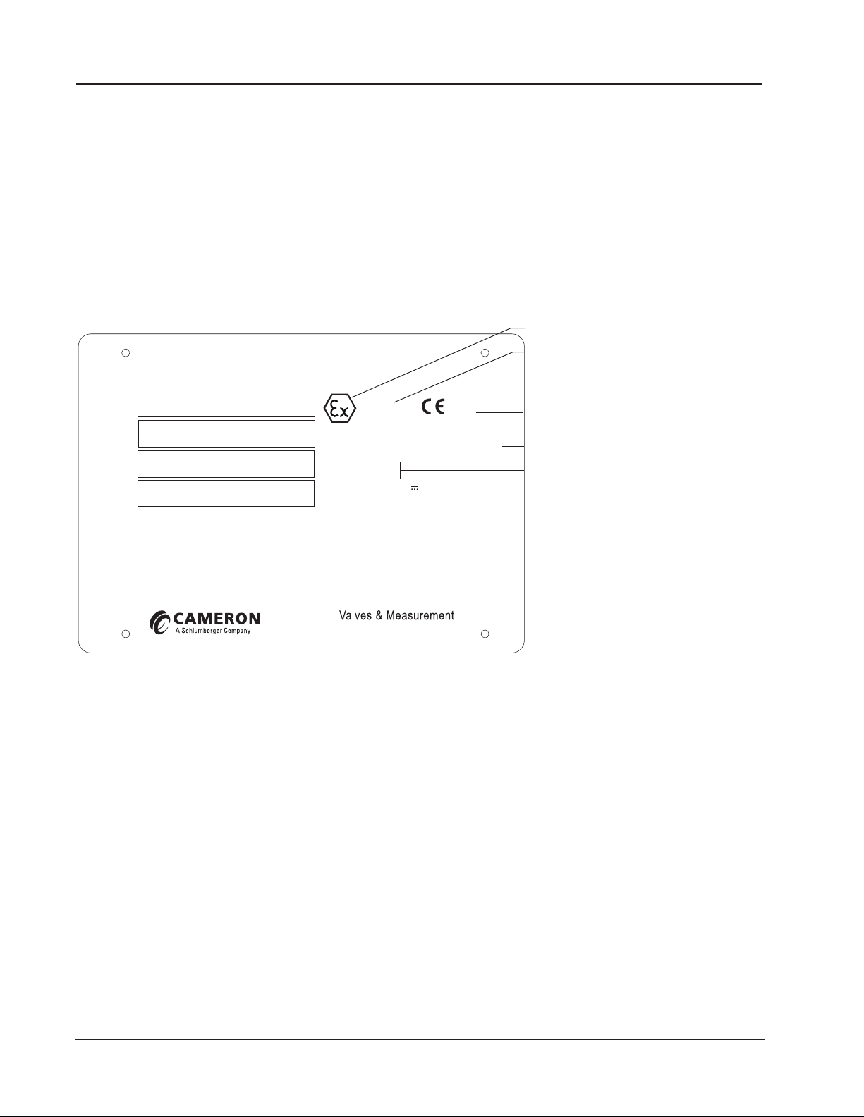
Explosion-proof marking
CE marking and number of notified body responsible
Section 1 Scanner 3100 EFM
Standard Features
The Scanner 3100 features a double-ended explosion-proof enclosure with four conduit openings for inputs/outputs, a
bottom conduit opening for a sensor, a large digital display, and a four-button keypad. Removing the front windowed
cover provides access to batteries and the keypad. The rear cover is removed for eld wiring. See Section 3—Wiring the
Scanner 3100 EFM, page 55 for wiring diagrams.
Product Identication
Each device is labeled with a serial tag that identies the product by model number and serial number and identies
the maximum operating pressure, working pressure, and differential pressure of the integral MVT (Figure 1.1). The tag
content depicted illustrates the electrical protection afforded by ATEX/IECEx certication. CSA-approved products are
marked accordingly with the respective ratings and symbols.
SCANNER 3100 EFM
MODEL
3100-
SERIAL
SP/SWP
PSIA
DP
IN H2O
WARNING: BATTERIES MUST ONLY BE CHANGED IN A NON-HAZARDOUS LOCATION.
WARNING: DO NOT OPEN WHEN AN EXPLOSIVE ATMOSPHERE IS PRESENT.
WARNING: ALL CABLE AND CABLE GLANDS MUST BE RATED FOR 80ºC.
FOR INSTALLATION AND OPERATION INFORMATION, SEE MANUAL PART NO. 2350759-01.
II 2 (1) GD
Ex d [ia Ga] ib IIC T5 Gb (Tamb -40°C to 70°C) or
Ex tb [ia Da] ib IIIC T100°C Db (Tamb -40°C to 70°C)
Sira 15ATEX 1122X
IECEx SIR15.0049X
INPUT POWER: 9 to 30V
7000 NIX DRIVE, DUNCAN, OK
@
150 mA
0518
Equipment Group II, Category 2
Hazardous conditions are likely to occur in normal
operation occasionally (>10<1000 hours/year);
Explosive atmosphere: Gas, Dust
for production
Flameproof for gas and dust; temperature class
Certification number
Figure 1.1—Device serial tag
Hardware Options
The following hardware options are available for customizing the Scanner 3100 to your specic needs: sensors, battery
packs, explosion-proof control switches, explosion-proof RTD assemblies, pole-mounting kits, and wireless communication components. See the sections below for details.
Sensors
The Scanner 3100 is available with no sensor or with an integral MVT (Figure 1.2, page 9). MVTs are available in
NACE and non-NACE models with bottom ports (gas measurement) or side ports (liquid measurement).
8
Page 9

MVT adapter
High pressure/
low pressure
port indicator
Integral
vent plugs
Multi-variable transmitter
(NACE-compliant MVT available)
Conduit entry
3/4-in. NPT
Ground
screw
Conduit plug
Antenna*
(available for wireless option)
Battery packs
Mounting boss
for pole mount
hardware
Antenna*
(available for wireless option)
SCANNER 3100 (NO SENSOR)
SCANNER 3100 + OPTIONAL MVT
*Remote-mount
antenna also
available.
Scanner 3100 EFM Section 1
Figure 1.2—Scanner 3100 sensor options
Battery Packs
Cameron’s dual lithium battery packs (Figure 1.3, page 10) provide backup power for the Scanner 3100. Battery life
can vary signicantly depending on the input and output congurations in use. For continuous operation, an external primary power supply is required (9 to 30 VDC at 150 mA; for Mexico installations, use 9 to 24 VDC at 150 mA).
WARNING: EXPLOSION RISK. Housing temperature must not exceed 70 degC (158 degF). Excessive tem-
peratures, which could result from ambient conditions combined with radiated and conductive heat from
!
the process, could cause the internal lithium battery to ignite or explode.
Each stick-style battery pack contains two 3.6 V batteries. Together, the dual packs can autonomously power the device
for a short period (approximately 2 to 3 weeks with a default conguration) in the event of a primary power outage. With
dual packs installed, you can replace a depleted battery pack without interrupting operations even when the device is operating solely on battery power.
9
Page 10
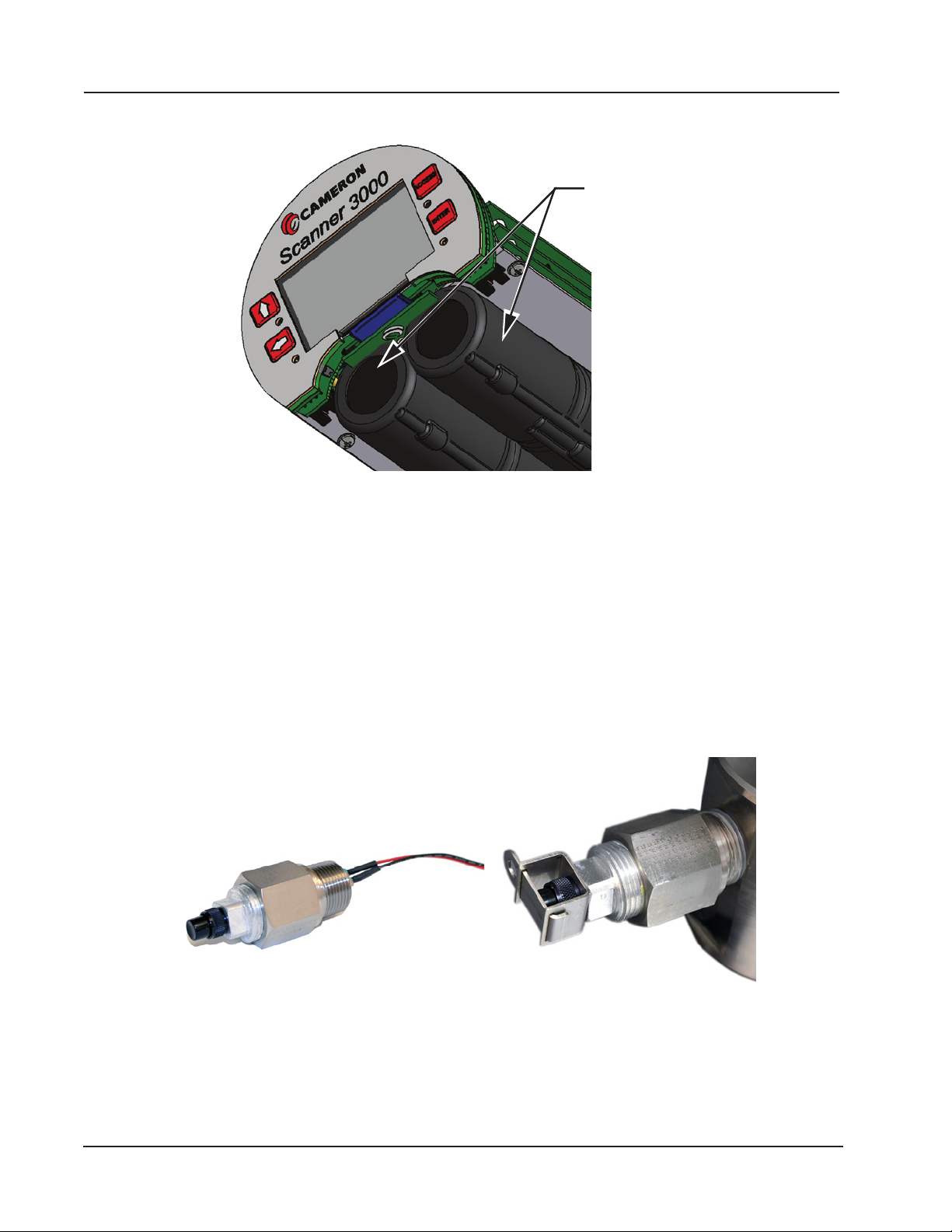
Battery packs
Section 1 Scanner 3100 EFM
For more information on battery replacement, see Lithium Battery Pack Replacement, page 85.
Figure 1.3—Lithium stick-style battery packs
Explosion-Proof Control Switch
An external explosion-proof control switch (Figure 1.4) allows you to manually control the operation of a peripheral device (such as a radio), unlatch an alarm, or reset a total being accumulated by the device, depending on how it is congured. The switch is available in either of two models:
• Toggle Switch. Opens or closes a circuit with each push and release of the button. Uses include manual control of
ow accumulation, and manual control of a triggered archive.
• Momentary Switch. Opens or closes a circuit when the button is pushed and held in position. Unlike the toggle
switch, the switch action is terminated upon release of the button. Uses include pacing the display, toggling a wireless
transmitter on and off, resetting grand totals for ow run or pulse input accumulations, unlatching a digital output, and
resetting a latch on a triggered archive.
Figure 1.4—Explosion-proof control switch (left); control switch with factory-installed safety lockout device (right)
Control switches are wired and pre-congured at the factory (Figure 1.5, page 11) when they are purchased with the
Scanner 3100. However, you can change the conguration via the web interface. A momentary switch is connected to
DIO Terminal 5 at the factory, and a toggle switch is connected to DIO Terminal 6. See Digital Inputs—Contact Closure,
page 61 and Digital Outputs, page 64 for wiring diagrams.
Either switch is available with a factory-installed mechanical lockout device (Figure 1.4, right) that can be used with a
10
Page 11
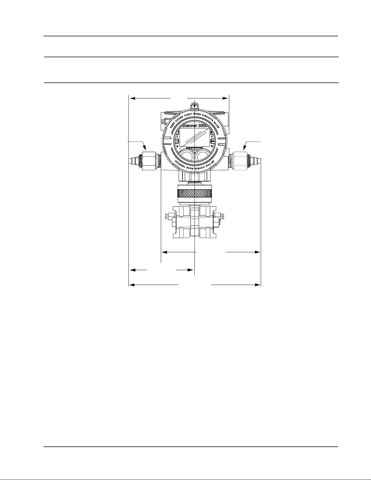
Approx. 8.0
Toggle switch
Momentary
(268)
Scanner 3100 EFM Section 1
lock or a seal to prevent unauthorized changes to the switch position as is sometimes required for audit compliance.
Important When a mechanical lockout device is required, the lockout must be installed in the switch at the
factory. A lockout mechanism cannot be added to an existing Scanner 3100 control switch after the
switch is installed.
(204.7)
switch
Approx. 8.0
(204.7)
Approx. 5.3
(134.07)
Figure 1.5—Control switch dimensions in inches (mm); the above diagram shows the default locations of factory-installed
switches
Approx. 10.6
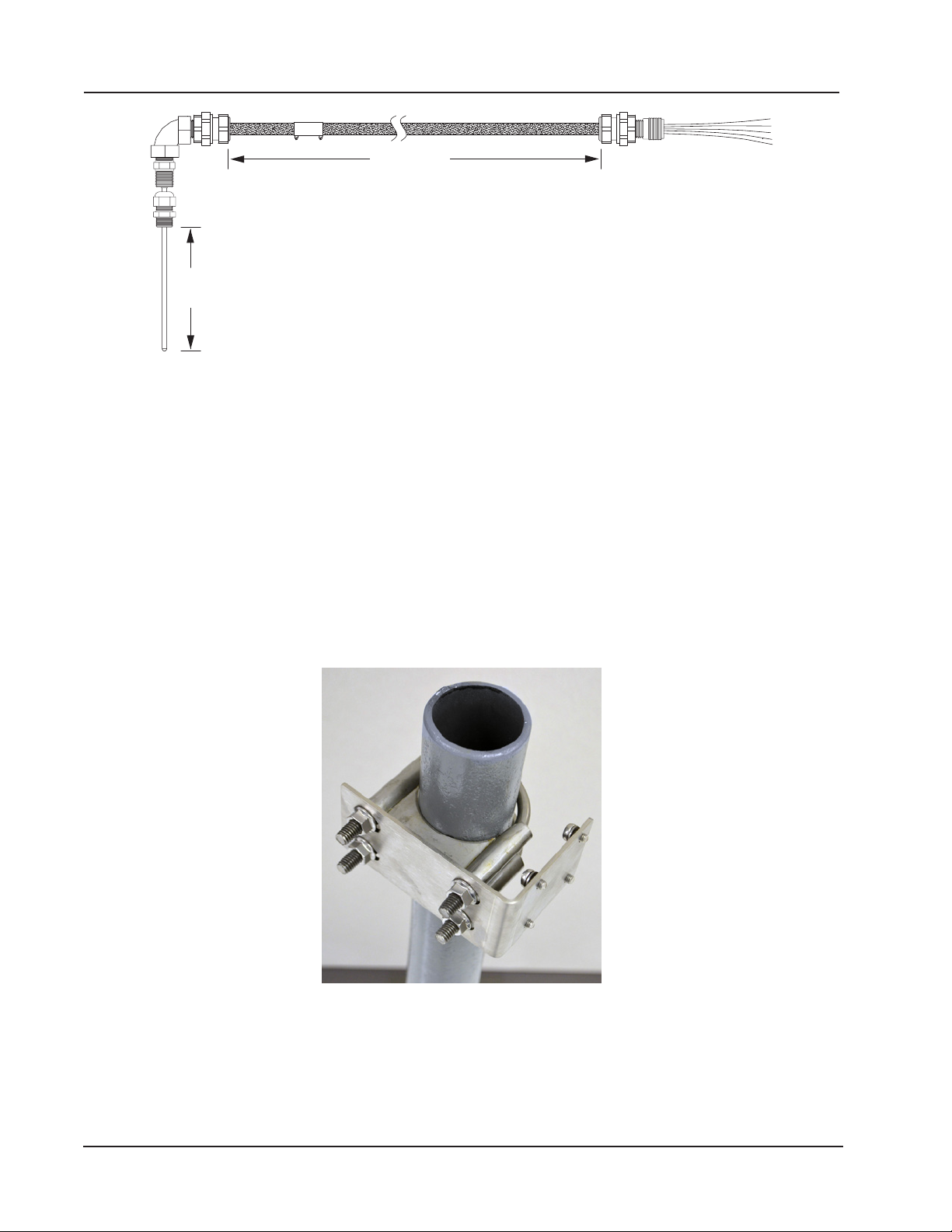
Explosion-Proof RTD Assembly
The Barton Model 21 RTD, shown in Figure 1.6, page 12, is a 4-wire, 100-ohm explosion-proof RTD assembly that
can be connected to the Scanner 3100 without conduit in a Class I, Division 1 installation. Factory-sealed, armored leads
are covered in PVC. The RTD assembly can be ordered with teck cable lengths of 5, 10, or 30 ft, and is available with a
6-in. or 12-in. RTD probe.
The Model 21 RTD is CSA certied for use in Class I, Groups B, C, and D; Class II, Groups E, F and G; and Class III
hazardous area environments.
Each RTD assembly is tted with 1/2-in. and 3/4-in. connectors for adapting to various size conduit openings and threadolets. The RTD is eld-adjustable for insertion lengths of up to 12 in. For wiring instructions, see Figure 3.6, page 59.
For part numbers, see Table 7.3—RTD and Cable Assemblies, page 89.
11
Page 12
Section 1 Scanner 3100 EFM
Cable length
Probe
length
Figure 1.6—Explosion-proof (Class I, Div. 1) RTD assembly
Flameproof RTD Assembly (ATEX, Zone 1)
Cameron offers a ameproof RTD that is ATEX-certied for use in Zone 1 installations. The 4-wire, Class A sensor is
encapsulated in a stainless steel sheath long enough to accommodate line sizes from 2 to 12 inches. It is attached to a
3500-mm armoured cable. For wiring instructions, see Figure 3.6, page 59. For part numbers, see Table 7.3—RTD and
Cable Assemblies, page 89.
Pole-Mounting Kits
Cameron’s pole mounting kit (Figure 1.7) is recommended for mounting a Scanner 3100 to a 2-in. pole. The kit consists
of a stainless steel “L” mounting bracket, two U-bolts, and four 10-mm M6 screws.
The bracket bolts directly to the four mounting bosses on the side of the Scanner enclosure and the U-bolts secure the assembly to the pole. For installation instructions, see Pole-Mounting the Scanner 3100, page 30. For part numbers, see
Table 7.1—Scanner 3100 EFM Parts, page 87.
Figure 1.7—Pole mounting kit
12
Page 13
and cable
Cameron direct-mount antenna
Scanner 3100 EFM Section 1
Wireless Communications
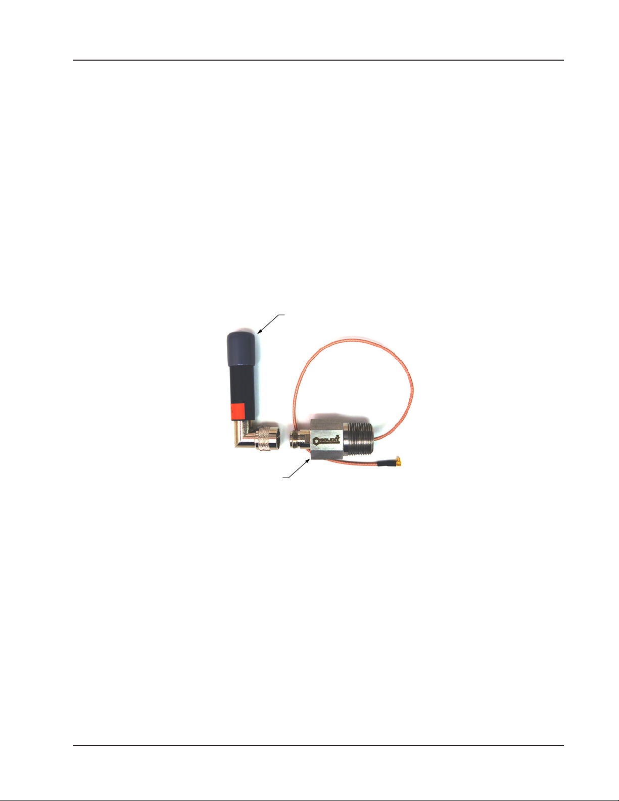
The Scanner 3100 wireless communications option includes a factory-installed wireless radio module and an explosionproof coupler (Figure 1.8) that enables an external antenna to be safely used in a hazardous area.
Explosion-proof Coupler
An explosion-proof coupler is factory-installed in the top left conduit opening of the Scanner 3100 enclosure and the
coupler cable is factory-connected to the radio module inside the Scanner 3100. The coupler is rated for compliance with
CSA (North America) or ATEX certication requirements. See Table 7.2—Wireless Components, page 88 for replace-
ment part numbers.
Direct-Mount Antenna
The Cameron-supplied right-angle antenna (Figure 1.8) connects directly to the threaded coupler connection. When installing the antenna, ensure that it is in a vertical position well above ground level and positioned away from large structures that could interfere with signal transmission and reception.
Cameron’s direct-mount antenna is rated for a maximum of 1 watt of power and a maximum antenna gain of 10 dB (in
North America) and has a frequency range of 2.35 to 2.50 GHz. Antennas with equivalent ratings may also be used with
the coupler.
Antenna coupler
Figure 1.8—Direct-mount antenna and explosion-proof antenna coupler (left); the coupler cable is factory-connected to
the Scanner 3100 enclosure
Remote-Mount Antenna
In locations where a physical barrier restricts the use of a direct-mount antenna or where a longer transmission distance
is required, a remote-mount antenna (Figure 1.9, page 14) may be installed up to 30 ft (10 m) away and connected by
cable to the antenna coupler. A remote-mount antenna and connecting cable may be purchased from Cameron (see Sec-
tion 7—Scanner 3100 Parts, page 87). If purchasing cable elsewhere, verify that the cable meets the maximum capaci-
tance and inductance ratings (Figure 2.5, page 32) and that the cable length is adequate to connect to both the antenna
and the coupler. See Specications, page 15 for additional details.
The installation of the antenna coupler, antennas, and antenna cable must meet the requirements shown in Figure 2.4 and
Figure 2.5, page 32. For installation instructions, see:
• Remote-Mount Antenna for Pole Outside Diameters up to 2 Inches, page 34
• Remote-Mount Antenna for Pipe Outside Diameters of 2 3/8 Inches, page 35
13
Page 14
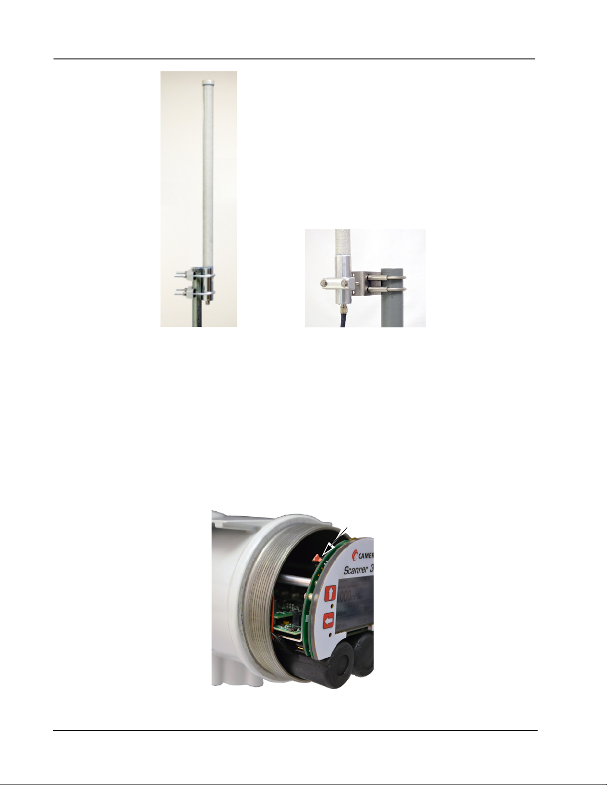
Mounting hardware supplied with
the Cameron remote-mount antenna
(fits pole outside diameters up to 2 inches)
Configuration
Section 1 Scanner 3100 EFM
Optional hardware kit for mounting the
Cameron remote-mount antenna to a
2-in. pipe (fits outside diameter of 2 3/8-in.)
Figure 1.9—Remote-mount antenna mounting options
Conguration Lock
The conguration lock is located inside the Scanner 3100 housing along the top edge of the display circuit board assembly, just left of center (Figure 1.10). The switch can be enabled to prevent unauthorized individuals from changing
the conguration of the Scanner 3100. By default, this conguration lock feature is disabled and the switch position is
ignored. The conguration lock feature must be enabled via the ADMINISTRATION>GENERAL>SECURITY page
of the Scanner 3100 web interface. For more information, see the Scanner 3100 Web Interface User Manual. After a device is fully congured, the lock can be enabled by changing the mechanical switch to the active position (pushed in the
direction of the display face) and enable the switch in the web interface security settings. After the lid is replaced, a wire
can be connected to an external set screw and secured with a lead seal to prevent unauthorized conguration changes.
Lock Switch
Figure 1.10—Conguration lock switch
14
Page 15

Scanner 3100 EFM Section 1
Specications
Table 1.1—General Specications
Approvals CSA (US and Canada)
Class I, Div. 1, Groups C and D, T4; Type 4 enclosure
ATEX 15ATEX1122X— Ex d [ia Ga] ib IIC T5 Gb (Tamb –40 degC to 70 degC; – 40 degF to
158 degF)
IECEx SIR 15.0049X— Ex tb [ia Da] ib IIIC T100 degC Db (Tamb –40 degC to 70 degC; –40
degF to 158 degF)
(IP66 protection from dust and water)
ANSI 12.27.01 single seal (MVT ≤ 3000 psi)
ASME pressure vessel code (MVT ≤ 3000 psi); CRN 0F10472.5C
Environmental
Safety
Enclosure Cast aluminum (less than 0.05% copper), painted with epoxy and polyurethane
Weight Base unit (no MVT or batteries) 4.1 kg (9.1 lb)
System Power External user-supplied power supply (9 to 30 VDC, 150 mA) with internal lithium battery
Real-time Clock Accurate within 2 minutes/year over temperature range
Processor 32-bit dual-core ARM Cortex M4
Operating
Temperature
WARNING: EXPLOSION RISK. Housing temperature must not exceed 70 degC (158 degF). Excessive
temperatures, which could result from ambient conditions combined with radiated and conductive heat from
the process, could cause the internal lithium battery to ignite or explode.
LCD Display/
Keypad
Memory 2.18 MB RAM for processing
Relative humidity: 0% to 95% non-condensing
Altitude: Up to 2000 meters
Double-ended with single window
Dimensions: 5.43 in. wide, 11.27 in. deep, 10.76 in. tall with MVT
5 conduit ports including bottom sensor port, 3/4-in. FNPT connections
Base + MVT and 2 batteries 8.3 kg (18.4 lb)
Base + MVT, direct-mount antenna, and 2 batteries 8.6 kg (19 lb)
backup.
For installations in Mexico, the power supply is limited to 9 to 24 VDC.
Two integral 7.2 V lithium stick-style battery packs, each containing two “D” batteries in series
(air transport regulations apply)
Lithium coin cell battery maintains clock during loss of system power (lithium content: 0.11 g)
–40 degC to 70 degC (–40 degF to 158 degF)
LCD contrast is reduced below –30 degC (–22 degF)
2.7-in. diagonal graphic display, 400 × 240 pixels
0.3-in. high characters
Displays up to 32 user-dened parameters (ve at a time), with auto-scrolling
External power indicator
Integral battery capacity indicators
Wireless communications indicator
Parameter status indicators
Congurable background (dark or light) and scroll frequency
4-button keypad for advancing the display; viewing communication settings, serial number,
and rmware version; and restoring factory default settings to the device
512 KB non-volatile memory for conguration data
32+1 MB on-board system ash memory
48 MB on-board archive ash memory
15
Page 16

Section 1 Scanner 3100 EFM
Table 1.1—General Specications
Supported
Met e r Types
Download Types Per Device Complete (all records, including slave device records as
Archive
Capacity
Communications/
Archive Retrieval
Turbine meter
Cone meter
Orice meter
Ultrasonic meter
Positive displacement (PD) meter
Coriolis meter
Venturi meter
applicable)
Local (integral ow records in a condensed le ideal for
emailing)
Events
Triggered (one-second logs, including PID tuning)
Per Flow Run Daily
Interval (hourly)
Event
Recent (past 7 days of interval logs)
Per Slave Daily
Interval (hourly)
Recent (past 7 days of interval logs)
Up to 58 archivable parameters per ow run
Daily log capacity 2,048 days
Interval log capacity 2.8 years with 13 parameters (plus date, time and status)
logged hourly
Capacity varies with the number of parameters logged (13 to
58) and logging frequency (1 second to 12 hours)
Triggered log capacity
(1 to 19 parameters)
Event log capacity 98,304 records
Downloadable via FTP, HTTP (web interface), or Enron Modbus protocol (see Scanner Data
Manager User Manual for information on viewing data les)
Logs stored in non-volatile memory for up to 10 years
Wireless Optional SmartMesh wireless radio module available with or
Wired RS-485 Two dedicated ports (1 and 2) and one shared RS-485/RS-
Wired RS-232 Shared RS-485/RS-232 port (port 3)
1,351,680 logs with one parameter logged;
135,168 logs with 19 parameters logged
Congurable to log periodically (1 second to 12 hours) on
a real-time period (daily, weekly, etc.) on device alarm, on
digital input, or when activated remotely via the web browser
without external antenna. See Table 1.2—Hardware Options,
page 20.
232 port (3)
Software-selectable 120-ohm termination resistor
Selectable master and slave protocols (Enron Modbus,
Modbus RTU, Modbus TCP)
TXD, RXD, RTS, CTS
Time-of-day digital output conguration
16
Page 17

Scanner 3100 EFM Section 1
Table 1.1—General Specications
Communications/
Archive Retrieval
(cont’d)
Flow Rate
Calculations
Fluid Property
Calculations
Liquid
Compensation and
Correction Factors
Flow Streams Two integral compensated ow run inputs
MVT
Specications
Ethernet/TCP One RJ- 45 connection supports two TCP/IP user-
congurable ports with selectable slave protocols
Continuous use requires external power
Supports 10/100 Mbits/second
Port Pass-Through Any communications port can be routed to another port
Ethernet can be bridged to serial communications for
remotely interfacing with connected Modbus devices.
(For example, a Scanner slave device can be congured
using ModWorX* Pro software without changing wiring
connections.)
Natural Gas AGA 3 (1992 and 2012), ISO 5167-2 (2003), ASME MFC-14M
(2003), AGA 7
Liquids API MPMS 5.3, AGA 3, ISO 5167, AGA 7
Natural Gas AGA 8 2017 (Parts 1 and 2), GERG-08, SGERG-88, AGA 3,
AGA 5, GPA 2145-09
Liquids API MPMS Chapter 11.1 (2004)
Pure Substances IAPWS-IF97 (Steam) Quality-corrected saturated steam,
water, dry steam, critical range (Regions 1 through 4)
Temperature and pressure compensation
Meter factor compensation
Shrinkage factor compensation
Live BS&W correction
Live density correction
Dynamic oil fraction (watercut)—derived from owing density or watercut analyzer; automatic
base density updates from owing density measurement
Chisholm-Steven orice meter multiphase correction for steam
Chisholm-Steven cone meter multiphase correction for steam
Up to 20 remote ow runs via Scanner 2000 Series devices in local area Scanner network
Three additional integral uncompensated pulse/frequency inputs
Bidirectional ow measurement
Up to 8 gas streams using gas chromatograph inputs or user-entered static compositions
16-point calibrations for all inputs (linear factory and multipoint meter factor calibrations also
supported); see Table 1.6—Flow Correction Factors, page 25 for information on multipoint
meter factor calibration
Stacked differential pressure and static pressure inputs for rangeability
Linearized digital data for static pressure (absolute) and differential pressure
Measures pressure in absolute and displays pressure in gauge
Standard MVT has bottom ports, which are ideal for gas measurement; MVT can be inverted
for liquid measurement (LCD autocorrects for easy viewing)*
Complies with pre-qualied materials of NACE MR0175/ISO 15156. This certification does
not imply or warrant the application of the product in compliance with NACE MR0175/ISO
15156 service conditions in which the customer/user installs the product.
Process temperature: –40 degC to 121 degC (–40 degF to 250 degF)
User-adjustable sample time (up to 10 Hz) and damping
*Side-port MVT for liquid measurement is available by special order.
17
Page 18
Section 1 Scanner 3100 EFM
Table 1.1—General Specications
MVT Accuracy Differential Pressure ± 0.05% of range for all except for 30 “H2O
± 0.1% of range for 30 “H2O
Static Pressure ± 0.05% of range
Temperature Effect ± 0.25% of full scale over operating range
Stability (long-term drift) Less than ± 0.05% of URL per year over a ve-year period
Resolution 24 bits
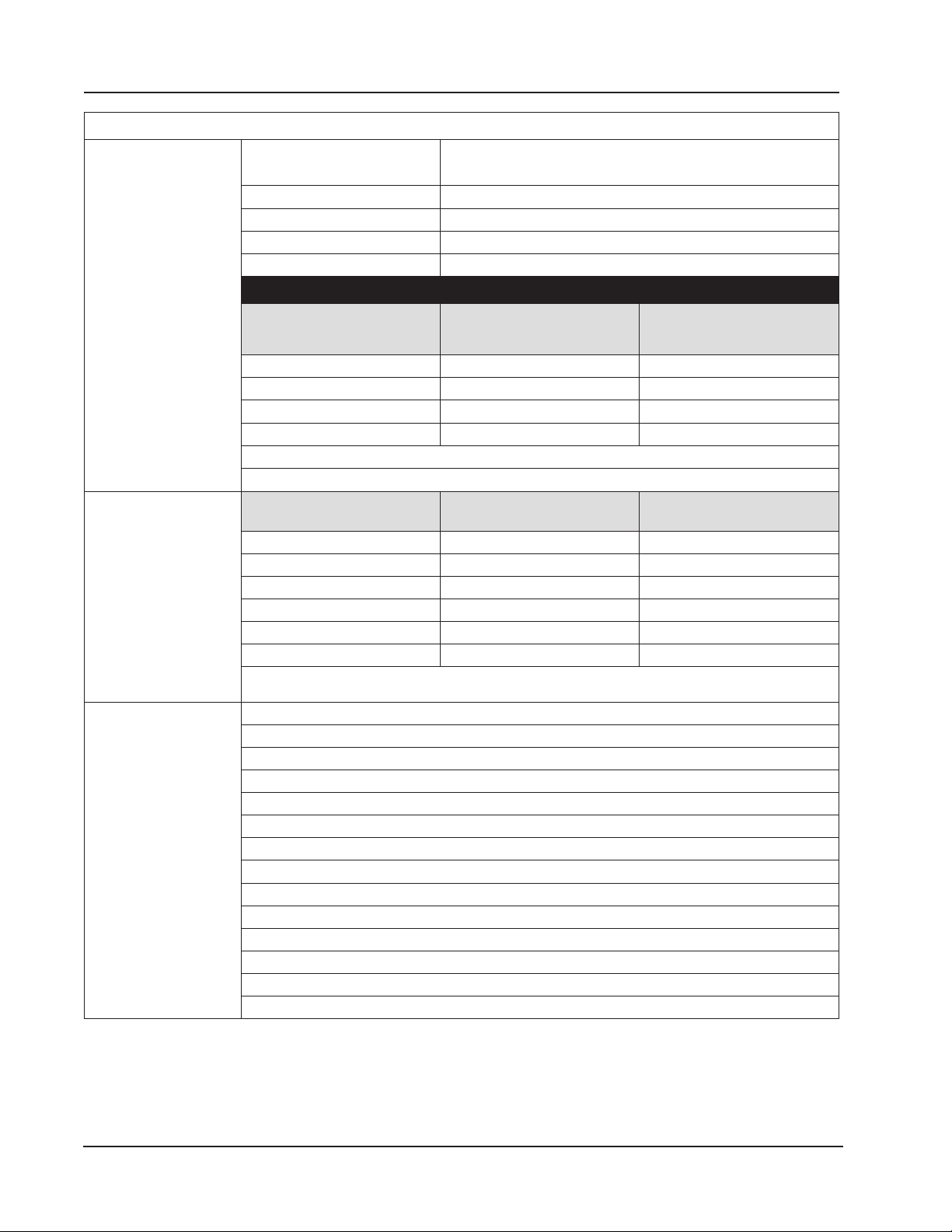
Effect on Differential Pressure for a 100-psi Pressure Change
Differential Pressure
Range (in. H2O)
*± Indicates bidirectional capabilities (for example, a range of 30 in. H2O is – 30 to +30 H2O).
**Exception: 200 x 300 psi has a zero shift of .007% and a span shift of .01%.
MVT Pressure
Static Pressure/SWP
Ranges
Custom ranges available by special order. For materials of construction, see Table 2.1—MVT Materials
and Bolt Specications, page 28.
Analog Inputs 4 channels
1 to 5 V, 0 to 5 V, 4 to 20 mA, or 0 to 20 mA
Accuracy: ± 0.030% of span maximum error at 25 degC (77 degF)
Temperature effect: ± 0.25% of span over operating range
Impedance: > 60 Kohm for 1 to 5 V input; approximately 250 ohm for 4 to 20 mA input
Transmitter voltage supply: 10 VDC at 20 mA, protected to 50 mA
Over-voltage protection: 30 VDC
A/D resolution: 22 bits (minimum 20 effective bits)
Linearity error: ± 0.020% max.; ± 0.010% typical
Single-ended inputs
Sample rate: 0.1 seconds to 12 hours
Four previous calibrations available stored in device
Congurable shutoff for saving power when transducer warm-up period is not required
Integral battery backup
Zero Shift
(% URL)
Span Shift
(% reading)
± 30* .05 .01
± 200** .01 .01
± 400 .04 .01
± 840 .04 .01
(psia)
100
Differential Pressure
(in. H2O)
30 150
Maximum Overrange
Pressure (psia)
300 200 or 840 450
500 30 or 200 750
1500 200, 400, or 840 2250
3000 200, 400, or 840 4500
5300 200, 400, or 840 7420
18
Page 19

Scanner 3100 EFM Section 1
Table 1.1—General Specications
RTD Inputs 2 channels
100-ohm platinum RTD with 2-wire, 3-wire, or 4-wire interface
Range: –40 degC to 427 degC (– 40 degF to 800 degF), excluding RTD uncertainty
Accuracy: ± 0.2 degC (0.36 degF) over sensing range at calibrated temperature
Temperature effect: ± 0.3 degC (0.54 degF) over operating range
A/D resolution: 24 bits
Sample rate: 0.1 seconds to 12 hours
Congurable shutoff for power savings when transducer warm-up period is not required
Pulse/Frequency
(TFM) Inputs
Analog Outputs 2 channels
Digital I/O 6 channels, user-congurable as input or output
3 channels
Maximum voltage: 30 VDC
Maximum frequency: 10,000 Hz
Gated transmitter power for each input channel
Transmitter voltage supply: 10 VDC at 20 mA, protected to 50 mA
TFM Channel 3 has no sleep mode and increased power consumption
Accumulation types: uncompensated gas volume, uncompensated liquid volume, mass
Volume: pulse represents discrete units of volume from a turbine, PD, Venturi, Coriolis, or
ultrasonic meter
Mass: pulse represents discrete units of mass from a Coriolis meter
Congurable turbine sensitivity (20, 50, 100 mV, peak-to-peak)
Type 4 to 20 mA, optically isolated, externally powered
Accuracy (after calibration): ± 0.1% of span maximum error at 25 degC (77 degF)
Temperature drift: ±50 ppm/degC (±27.8 ppm/degF)
Maximum output load resistance (ohms) = {supply (volts) – 8.0} / 0.02
Maximum voltage: 30 VDC
D/A resolution: 16 bits
Calibration (zero and full-scale) via software
Programmable output alarm value for use during loss of power or communication to CPU
Regulates control valve in PID control applications
DIO1, DIO2, DIO3, and DIO4 are optically isolated with a max. output of 60 mA at 30 VDC
DIO5 and DIO6 are high-speed and non-isolated with a max. output of 500 mA at 30 VDC
Input Types Control switch
Pulse
Open collector
Contact closure
Special Functions Advance display
Turn transmitter on/off
Reset ow run totals
Reset pulse input totals
Unlatch digital inputs/outputs
Reset latching state of triggered archive
19
Page 20

Section 1 Scanner 3100 EFM
Table 1.1—General Specications
Digital I/O (cont’d) Output Modes Pulse (based on pulse count or time period)
Alarm (based on the status of any or all selected alarms; up
to 32 user-congured alarms are selectable)
Conditional (value above or below setpoint, out of setpoint
range)
Programmed [time of day or output state (normally open,
normally closed)]
Pulse Output Maximum frequency: 50 Hz
Congurable pulse duration (10 msec to 1 day)
Congurable pulse representation (1 pulse = 1 MCF) based
on time or volume
Based on any accumulator (ow run or turbine meter run)
Alarm Output Low/high
Out-of-range
Status/diagnostic
Web Interface—
Local Device
Management
Web Inter face—
Network
Management
Access data and device settings via laptop, tablet, or smartphone
Congure, calibrate, and maintain ow runs, inputs/outputs, and gas streams
Poll real-time data
Download data
View daily logs and up to 7 days of interval (recent) logs
Control user access with four levels of security
Congure communications with up to 20 wired or wireless Scanner 2000 Series devices
Display real-time data, ow rate calculation method, and input averages for up to 20 slave
devices
Read and store conguration data from up to 20 slave devices
Read and store daily and interval archive records for up to 20 slave devices
Change gas composition and plate size in slave device congurations
Download slave data via FTP, HTTP, or Enron Modbus protocol
Synchronize slave device conguration and slave archive data
Read gas streams connected to slave devices
Clear slave device grand totals and alarms
Load factory default conguration le
Remotely reset slave device without cycling power
Wireless
SmartMesh Radio
20
Table 1.2—Hardware Options
2.4 GHz self-healing and self-sustaining network
Factory installed with stainless steel, explosion-proof antenna coupler, N female × 3/4 MNPT,
with 12-in. coaxial cable and MMCX male connector
Transmits up to 300 m (985 ft) node-to-node
Page 21

Scanner 3100 EFM Section 1
Table 1.2—Hardware Options
Radio Certications Supports communications with up to 20 remote Scanner 2000 Series devices (each Scanner
node can transmit and receive data)
Radio certications (by country):
Argentina: CNC
Australia/New Zealand: ACMA, R-NZ (Z571 Limited), C-Tick
Bahrain: TRA
Ecuador
Egypt: NRTA
Europe: CE Mark, R&TTE
India
Indonesia: SDPPI
Mexico: IFETEL
North America: FCC/IC
Oman, TRA
Qatar
Thailand
United Arab Emirates, TRA
Venezuela
Antenna
Electrical Properties
Frequency Range 2.35 to 2.50 GHz 2.4 to 2.5 GHz
Impedance 50 ohms nominal at 2.4 GHz 50 ohms nominal at 2.4 GHz
Voltage Standing Wave
Range (VSWR)
Connector N male brass nickel-plated
Height 95.25 mm (3.75 in.) 800 mm (32.28 in.)
Shape Elbow (right angle) Straight
Material UV-resistant ABS Fiberglass
Operating Temperature –40 degC to 80 degC (–40
Pole Mount Hardware
— N/A Standard hardware (included
— N/A Alternate remote-mount kit
Antenna Cable Length N/A 10-, 20-, and 30-ft with
Type N/A Type 400
Temperature Range N/A –40 degC to 70 degC (–40
Direct-Mount Remote-Mount
1.13:1 <1.5
N female brass nickel-plated
connector for use with N
female explosion-proof/
intrinsically-safe coupler
degF to 176 degF)
connector, cable required
for connection to N female
explosion-proof coupler
–40 degC to 80 degC (–40
degF to 176 degF)
with antenna) ts pole with
outside diameter up to 2 in.
available for pipe with outside
diameter of 2 3/8 in.
connectors
degF to 158 degF)
21
Page 22

Section 1 Scanner 3100 EFM
Table 1.2—Hardware Options
Control Switch (CSAor ATEX-Approved)
Remote-Mount Kit Stainless steel mounting kit for 2-in. poles (mounts to the side of the electrical enclosure)
RTD Temperature
Sensor
Thermowell Nominal 6.6 mm (0.26 in.) bore, 1/2-in. FNPT instrument connection
5-Valve Manifold Consult factory for direct-mount or remote-mount manifold and materials
Portable Ethernet
Router
Customer Tag Stainless steel tag for customer-specied information, 3 in. × 3 in., wired on, 5 lines of text, 45
Explosion-proof switch*, momentary contact, ts 3.4 in. female pipe thread (uses include
pacing the display, toggling a wireless transmitter on and off, resetting ow run or pulse input
grand totals, unlatching a digital output, and resetting a triggered archive latch)
Explosion-proof switch*, toggle action, ts 3.4 in. female pipe thread (uses include manual
control of ow accumulation and manual control of a triggered archive)
*Switch can be ordered with a factory-installed mechanical lockout mechanism for preventing
unauthorized users from changing the switch position.
4-wire, 100-ohm explosion-proof RTD assembly suitable for CSA Class 1, Div. 1 installations
4-wire, Class A sensor encapsulated by a stainless steel sheath and attached to a 3500 mm
(11.48 ft) armoured cable
Consult factory for various materials, process connections, insertion lengths ,and options
Supports connection of a PC or other browser-based device to a Scanner 3100 ow
computer. Connects to Scanner with RJ-45 cable and connect to PC via WiFi. Available in
USB- or battery-powered models. See Wireless Communications, page 13 for additional
WiFi solutions.
character per line maximum
Table 1.3—Scanner Companion Software
Important To download software or software user manuals, visit the Cameron website at
products.slb.com, select Scanner 3100 Series Wired and Wireless, and click on the link for the
desired software install/manual.
Scanner Logic
IDE
Scanner Data
Manager
ScanMap Creates custom Scanner 3100 Modbus register maps, including user-specied units, rates, and
ScanFlash Uploads rmware (BIN), conguration (SRF), Scanner Logic IDE le (SLBIN), and custom Modbus
PC Requirements
Windows 7 or later operating system
1 GHz or faster 32-bit (x86) or 64-bit (x64) processor
1 GB RAM (32-bit) or 2 GB RAM (64-bit) available hard disk space (135 MB for companion software installation, 30 MB
for Adobe Reader, adequate space for data les)
DirectX 9 graphics device with WDDM 1.0 or later driver
Creates Scanner Logic scripts (SLOGIC) and compiles them into a logic-controller program le
(SLBIN).
Performs live debugging on scripts, showing immediate and upcoming script sections to be
debugged.
Uses a high-level procedural programming language designed to build logic controllers. In this way,
the program resembles a state machine.
Opens proprietary data les (.sdf) downloaded from the Scanner 3100 and provides tools for data
analysis, reporting, export and conversion
Presents data in tabular and trend views
Includes tools for customizing reports
register names for SCADA integration
Firmware-specic templates
Auto-generates protocol manual for printing or uploading to the web interface
register map (PMAP) les to the Scanner 3100
22
Page 23

Scanner 3100 EFM Section 1
Flow Rate and Fluid Property Calculations
The Scanner 3100 calculates ow rates and uid properties for natural gas and liquid ow in accordance with the following industry standards. The calculations compensate for the effects of pressure, temperature, and uid composition to
determine mass and volume at specied base conditions. The uid corrections typically require conguration of inputs
including static pressure and temperature. The ow calculation requires conguration of differential pressure or pulse
(frequency) inputs.
Table 1.4—Flow Rate Standards
Standard Description
AGA 3
(1992)
AGA 3
(2012)
ISO 5167-2
(2003)
ISO 5167-4
(2003)
ASME
MFC-14M
(2003)
AGA 7 (2006) AGA 7 provides the measurement standards used to calculate natural gas
Miller
Handbook,
Third Ed.
The Scanner 3100 supports the orice metering calculations described in AGA
Report No. 3 (1992). This meter covers pipe sizes of nominal 2-in. and larger;
there is no stated maximum limit, but the largest size listed in the standard is
nominal 36 inch. Beta ratio must lie between 0.1 and 0.75. The AGA 3 orice
meter can be used to measure natural gas and liquids.
The Scanner 3100 supports the orice metering calculations described in
AGA Report No. 3 (2012). The AGA 3 orice meter covers pipe sizes of
nominal 2-in. and larger; there is no stated maximum limit, but the largest size
listed in the standard is nominal 36-in. Beta ratio must lie between 0.1 and
0.75. The 2012 report offers an improved expansion factor correction and is
recommended for use except where contractual or regulatory requirements
specify the 1992 standard. The AGA 3 orice meter can be used to measure
natural gas and liquids.
ISO 5167-2 describes the measurement of natural gas and liquids with an
orice meter using pipe sizes of nominal 50 mm (2 in.) to a maximum of 1000
mm (39 in.). Beta ratio must lie between 0.1 and 0.75. In ASME MFC-3M
(2004), the ISO-5167 orice ow calculation was adopted without modication.
The ISO orice meter can be used to measure natural gas and liquids.
ISO 5167-4 provides information for calculating ow rates with Venturi tubes.
It is applicable only to Venturi tubes in which the ow remains subsonic
throughout the measuring section and where the uid can be considered
as single-phase. In addition, each of these devices can only be used within
specied limits of pipe size, roughness, diameter ratio and Reynolds number.
ISO 5167 4 is not applicable to the measurement of pulsating ow. It does not
cover the use of Venturi tubes in pipes sized less than 50 mm or more than
1200 mm, or for where the pipe Reynolds numbers are below 20000.
For low ow applications, the Scanner 3100 supports the small bore orice
described in ASME MFC-14M for use with nominal 1/2-in. to 1-1/2-in. pipe
sizes. Beta ratio must lie between 0.1 and 0.75. The ASME small bore orice
meter can be used to measure natural gas and liquids.
ow rates from linear pulse output meters, including turbine meters, vortex
shedding meters, pulser-equipped positive displacement (PD) meters, Coriolis
meters having volumetric pulse output, and other types. Linear pulse output
meters can be used to measure natural gas and liquids.
Richard Miller’s Flow Measurement Engineering Handbook provides denitive
information on selecting, sizing, and performing pipe-ow-rate calculations,
using ISO and ANSI standards in both SI and US equivalents. This reference
also presents physical property data, support material for important uid
properties, accuracy estimation and installation requirements for all commonly
used ow meters.
Orice
NuFlo Cone
Linear Pulse
Output
Venturi
♦
♦
♦
♦
♦
♦
♦
23
Page 24

Section 1 Scanner 3100 EFM
Table 1.5—Fluid Property and Energy Flow Calculations
Standard Description
AGA 5 (2009) AGA 5 provides the methods for computing the mass, molar, and volumetric heating
values of natural gas at reference temperature. AGA 5 is also used in calculating related properties, including Wobbe index, motor octane number, and net (inferior) volume heating value. AGA 5 supports an intermediate calculation and therefore is not a
standard uid property selection in the Scanner 3100 web interface.
AGA 8, Part 1,
Detailed (2017)
AGA 8, Part 1,
Gross (2017);
SGerg-88
(1988)
AGA 8, Part 2,
Gross (2017);
Gerg-2008
(2012)
API MPMS
Chapter 11.1
(2004)
API MPMS
Chapter 20.1
(2011)
The worldwide standard for calculating the physical properties of natural gas and
similar gases is the AGA 8 92DC equation originally described in AGA Report No. 8
(1992). The 2017 edition, Part 1, uses the same DETAIL equations of state as in the
1994 edition of AGA 8. However, the temperature, pressure, and gas composition
limits have been modied in this edition.
Use of this calculation requires a gas analysis, i.e. knowledge of the mole fractions of
21 gas components: the alkanes methane through decane, common diluents including nitrogen, carbon dioxide, hydrogen sulde, and assorted trace components. In
ISO 12213-2 (1997), the AGA 8 92DC equation was adopted without modication.
The AGA 8 92DC equation is most accurate between temperatures of 17 degF and
143 degF (–8 degC to 62 degC) and at pressures up to 1,750 psia (12 MPa). If lesser
accuracy is acceptable, the range can be extended from –200 degF to 400 degF
(–130 degC to 200 degC) and pressures up to 20,000 psi (140 MPa). This uid calculation will provide the computed value for Speed of Sound.
When the detailed composition of the gas is unknown, an alternative method of characterizing the gas is available. It is based on the gross properties: real gas relative density
(gas gravity), and content of carbon dioxide and nitrogen. This method detailed in AGA
8 and ISO 12213-3 is based on the SGerg-88 equation. The Gross Characterization
method should only be used at temperatures between 17 degF and 143 degF (–8
degC to 62 degC) and at pressures below 1,750 psia (12 MPa). Gravity range is from
0.554 to 0.87; up to 28.94% carbon dioxide, and up to 53.6% nitrogen. This method
should not be used outside of these limits.
AGA 8, Part II uses temperature, pressure, and gas molar composition to compute
uid density at base and owing conditions. AGA 8, Part II is used with a ow calculation to determine uid ow rate.
The temperature and pressure correction factors for hydrocarbon liquids including
crude oil, rened products (gasoline, jet fuel, fuel oils), lubricating oils, and special
products are calculated according to API MPMS Chapter 11.1 (2004). For crude oils,
the density range is 610.6 to 1,163.5 kg/m3, temperature range is from –58 degF to
302 degF (–50 degC to 150 degC), and pressure range is from 0 to 1,500 psig (0 to
10,340 kPa). For differential pressure meters, the viscosity at operating temperature
is a required input to the ow computer, and it must be determined as accurately as
possible.
API MPMS Chapter 20.1, Section 1.9.5.4, provides procedure for computing net oil
volume in an oil/water mixture when watercut is higher than normal and a dynamic
sampling method, such as an online watercut analyzer, is used to measure watercut,
incorporating a shrinkage factor where applicable.
Natural Gas
♦ ♦
♦
♦
♦
Hydrocarbon
Liquid
Steam
♦
♦
24
Page 25
Scanner 3100 EFM Section 1
Table 1.5—Fluid Property and Energy Flow Calculations
Standard Description
GPA 2145
(2008)
ISO 6976
(1995)
IAPWS-IF97,
Saturated
Steam
IAPWS-IF97,
All Regions
GPA 2145 is a compilation of numerical values for the parafn hydrocarbons and
other compounds occurring in natural gas and natural gas liquids as well as for a few
other compounds of interest to the industry. GPA 2145 supports an intermediate cal-
culation and therefore is not a standard uid property selection in the Scanner 3100
web interface.
ISO 6976 species methods for the calculation of the superior caloric value and the
inferior caloric value, density, relative density and Wobbe index of dry natural gas
and other combustible gaseous fuels, when the composition of the gas by mole fraction is known. A simplied version of the AGA 5 calculation, ISO 6976 supports an
intermediate calculation and therefore is not a standard uid property selection in the
Scanner 3100 web interface.
IAPWS Industrial Formulation 1997 for the Thermodynamic Properties of Water and
Steam. This calculation should be used when the steam is assumed to be at the
saturation temperature at a given owing pressure. Only a pressure input is required.
Providing a steam quality measurement will yield an estimated liquid owrate and
produce accumulations for vapor and liquid water.
IAPWS Industrial Formulation 1997 for the Thermodynamic Properties of Water and
Steam. This calculation should be used when measuring in regions off the saturation
line operating conditions and when the water is liquid or super-heated. A pressure
input and a temperature input are required. From the owing condition inputs, the
operating region of the water is detected: liquid water (Region 1), dry steam (Region
2), critical range (Region 3), and saturated steam (Region 4). All regions except liquid
water are accumulated as vapor.
Natural Gas
Hydrocarbon
Liquid
Steam
♦
♦
♦
♦
Flow Correction Factors
The Scanner 3100 measures compensated petroleum liquid ow using an orice or cone ow meter. For accuracy, these
measurements often include a correction factor to compensate for the effect of gas or water on volume, or changes in
calibration. Table 1.6 describes the correction factors congurable in the Scanner 3100 web interface.
Table 1.6—Flow Correction Factors
Flow Correction Factor Description
Multipoint Meter Factor
Correction (for Gas and
Liquid)
Chisholm-Steven Orice
Meter Multiphase
Correction (for Steam)
The multipoint meter factor calibration method allows users to compensate for
variations between calibrations without changing the meter K-factor from the value
stamped on the meter at the factory. Meter factors are typically determined through
calibrations performed by third-party test laboratories. You can enter the appropriate
factor during calibration to account for any variation in the calibration curve over
Reynolds numbers.
The Chisholm-Steven correction method is used for over-reading prediction in wet
vapor ow conditions (multiphase) for water at the owing conditions along the
saturation line. When provided with a quality measurement, the vapor ow is corrected
and the estimated liquid ow is accumulated.
25
Page 26
Section 1 Scanner 3100 EFM
Table 1.6—Flow Correction Factors
Flow Correction Factor Description
Crude Oil Shrinkage
Factor
Base Sediment and Water
(BS&W) Correction Factor
This correction factor allows users who are measuring crude oil to automatically
correct their liquid volume measurements for the effects of gas content. When the oil
is discharged from a pipeline to a stock tank at atmospheric conditions, the volatile
components in the oil evaporate, causing a reduction in liquid volume. When live oils
are metered (e.g., test separators), a shrinkage factor must be applied to correct the
measured liquid volume from the metering pressure and temperature to stock tank
conditions unless the meter is proved to stock tank conditions. Shrinkage volumes are
typically obtained with a shrinkage tester. This correction method will correct the meter
reading for both dissolved gas and for oil volume reduction. It will not compensate for
the effects of uid viscosity changes. Shrinkage volumes or factors are often used to
mitigate safety and environmental concerns when live oil volumes are measured at high
pressures or when the live oil contains hydrogen sulde (H2S).
Crude oil generally contains some water. The BS&W correction provides a means
of discounting the water content and totalizing only the crude. The correction can be
based on a user-entered value (assumed to be constant) or on a watercut monitor/
BS&W monitor output to the Scanner 3100 via a 4-20 mA signal.
26
Page 27

Scanner 3100 EFM Section 2
Section 2—Installing the Scanner 3100 EFM
Overview
The Scanner 3100 ow computer is fully assembled at the time of shipment and ready for mounting. However, Cameron
recommends that operators congure the EFM prior to mounting if the instrument is to be installed in a hazardous area.
The enclosure must be opened to congure the device, either via keypad controls or via software, and once the instrument is mounted in a hazardous area, the cover should not be removed unless the area is void of combustible gas and
vapors.
Hazardous Area Precautions
The Scanner 3100 is ATEX/IECEx-certied (Zone 1) and CSA-certied (Class I, Div. 1) for hazardous area use. Installation requirements vary, depending on the certication required. Carefully review the following hazardous area requirements before installing a Scanner 3100 in a hazardous area.
ATEX Installations (Conditions for Safe Use)
The ATEX-certied standard Scanner 3100 is fully compliant with European ATEX Directive 94/9/EC and has been
evaluated per the following standards:
• IECEx: IEC 60079-0:2011, Edition 6, IEC 60079-1:2007-04, Edition 6, IEC 60079-11:2006, Edition 5, and IEC
60079-31:2013, Edition 2
• ATEX: EN 60079-0:2012, EN 60079-1:2007, EN 60079-11:2012, EN 60079-31:2014
The following instructions apply to equipment covered by certicate numbers Sira15ATEX 1122X and IECEx SIR
15.0049X:
• When removing the conduit plug to t the data transfer socket to the communication adaptor and during data
transfer, the user/installer shall ensure that no explosive atmosphere is present. After data transfer has nished, the
conduit plug shall be retted in accordance with the relevant Code of Practice.
• Under rated conditions, the branching point at the entry point may reach 80 degC (176 degF); therefore, when
choosing cables and cable glands, this shall be taken into account.
• When removing or replacing the internal battery packs, this shall be done in accordance with the user instructions
provided by the manufacturer, and the user/installer shall ensure that no explosive atmosphere is present.
• The user/installer shall install this equipment taking into account any restrictions or special conditions for safe use that
are applicable to the previously certied devices that are used in its construction.
Wiring Precautions
CAUTION In accordance with EN60079-0, Clause 16.6, all cable and cable glands must be rated for 80 degC
(176 degF). The Scanner 3100 may be tted as a remote unit when all the cable entries are tted
with ameproof glands that have been suitably certied by a notied body.
RTD Assembly Options (for Gas and Liquid Flow Runs Only)
The process temperature input is typically supplied by an RTD installed in a thermowell downstream of the primary
differential pressure source. The location of the thermowell should conform to the relative standard to ensure accurate
measurement. Use only an RTD assembly that is tted with a suitably certied, Ex d IIC cable entry gland, such as the
ameproof RTD (Part No. 9A-X-TTXR-0003) listed in Table 7.1—Scanner 3100 EFM Parts, page 87.
27
Page 28
Section 2 Scanner 3100 EFM
CSA Installations
The Scanner 3100 is CSA-certied as explosion-proof for Class I, Division 1, Groups C and D hazardous locations.
Wiring Precautions
CAUTION All eld wiring must conform to the National Electrical Code, NFPA 70, Article 501-4(b) for installa-
tions within the United States or the Canadian Electric Code for installations within Canada. Local
wiring ordinances may also apply. The cable used between the Scanner 3100 and other devices
must be either armored MC-HL cable or standard cable routed through conduit. If standard cable is
used, a conduit seal must be installed within 6 inches of the Scanner.
Pressure Precautions
WARNING: Before connecting the Scanner 3100 to a ow line, consider the pressure rating of the sensor
!
and the presence of harmful gases. The tubing and xtures used to connect the sensor to the manifold
in the ow line must be manufactured from materials that are appropriate for the pressure ratings of the
sensor used. If H2S is present, use a NACE sensor and take appropriate precautions to avoid exposure to
this hazardous gas.
Table 2.1—MVT Materials and Bolt Specications
MVT Materials of Construction
Process Cover 316 SS (other materials available by special order)
Process Cover Gasket Glass-lled PTFE
Diaphragm 316L SS (other materials available by special order)
Vent/drain SS bleed (316SS plug optional for NACE and coastal applications)
Body Bolts and Nuts (non-process wetted)
B7/2H
alloy steel
Conguration
Standard Yes No Yes Ye s Yes
NACE No Ye s No No Yes
Coastal
Max. Pressure Range
Coating Plated Black oxide None None None
1
B7 and B7M alloy steel is susceptible to rust. Other materials may be preferred for offshore use.
2
316 SS bolts have a CRN safe working pressure limit of 2725 psi.
3
5300-psi ranges require transducer code HP and have a CRN safe working pressure limit of 3625
psi. Single seal is limited to 3000 psi.
4
5300-psi ranges require transducer code HP and are not available with a Canadian CRN. 5300-psi
range has a CRN SWP limit of 3710 psi. Therefore, it is possible to measure to 3710 psi and remain
in CRN compliance. Single seal is limited to 3000 psi.
Yes Yes
5300
B7M/2HM
alloy steel 316SS 17-4 PH SS Inconel 718
Yes No Ye s
1500 1500 3000 5300
Note A four-port MVT adapter has been evaluated by CSA for use with the Scanner 3100 but is not released for pro-
duction at this time. Seals must be installed at each port for CSA compliance. The four-port MVT adapter has not
been evaluated for ATEX approval.
28
Page 29
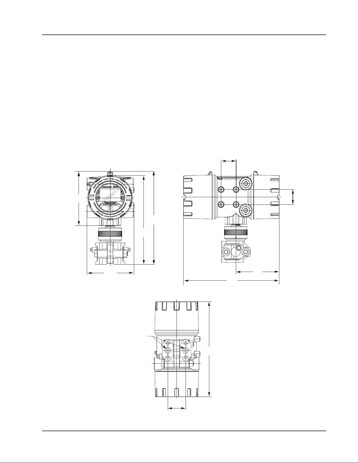
(161.4)
Scanner 3100 EFM Section 2
Thermowell Location (for Gas and Liquid Flow Runs Only)
The process temperature input is typically supplied by an RTD installed in a thermowell downstream of the primary differential pressure source using a 2-wire, 3-wire, or 4-wire RTD assembly. To ensure accurate measurement, the location
of the thermowell should conform to the appropriate standard.
Mounting Options
The Scanner 3100 can be mounted using the following methods:
• Direct-mount to an orifice or cone type differential pressure meter. The MVT shown in Figure 2.1 (with antenna
in Figure 2.3, page 31) may be connected to the pressure taps with stabilizers or a heavy wall nipple with adapter
anges, and a 5-valve manifold. A bottom-port MVT is recommended for gas measurement; a side-mount MVT is
recommended for liquid measurement.
• Pole-mount. The instrument can be mounted on a 2-in. pole using the mounting bosses on the side of the enclosure
and a Cameron pole mount kit (as shown in Figure 2.2, page 30). Tubing is used to connect the MVT to the orice
meter or cone meter.
1.77
(45.00)
6.35
5.43
(138.00)
10.28
(261.04)
1/4-18 NPT
process
connections
10.76
(273.18)
11.27
(286.29)
11.28
(286.29)
5.12
(129.93)
1.77
(45.00)
2.125
(53.98)
Figure 2.1—Scanner 3100 with MVT, direct-mount; dimensions shown in inches (mm)
29
Page 30
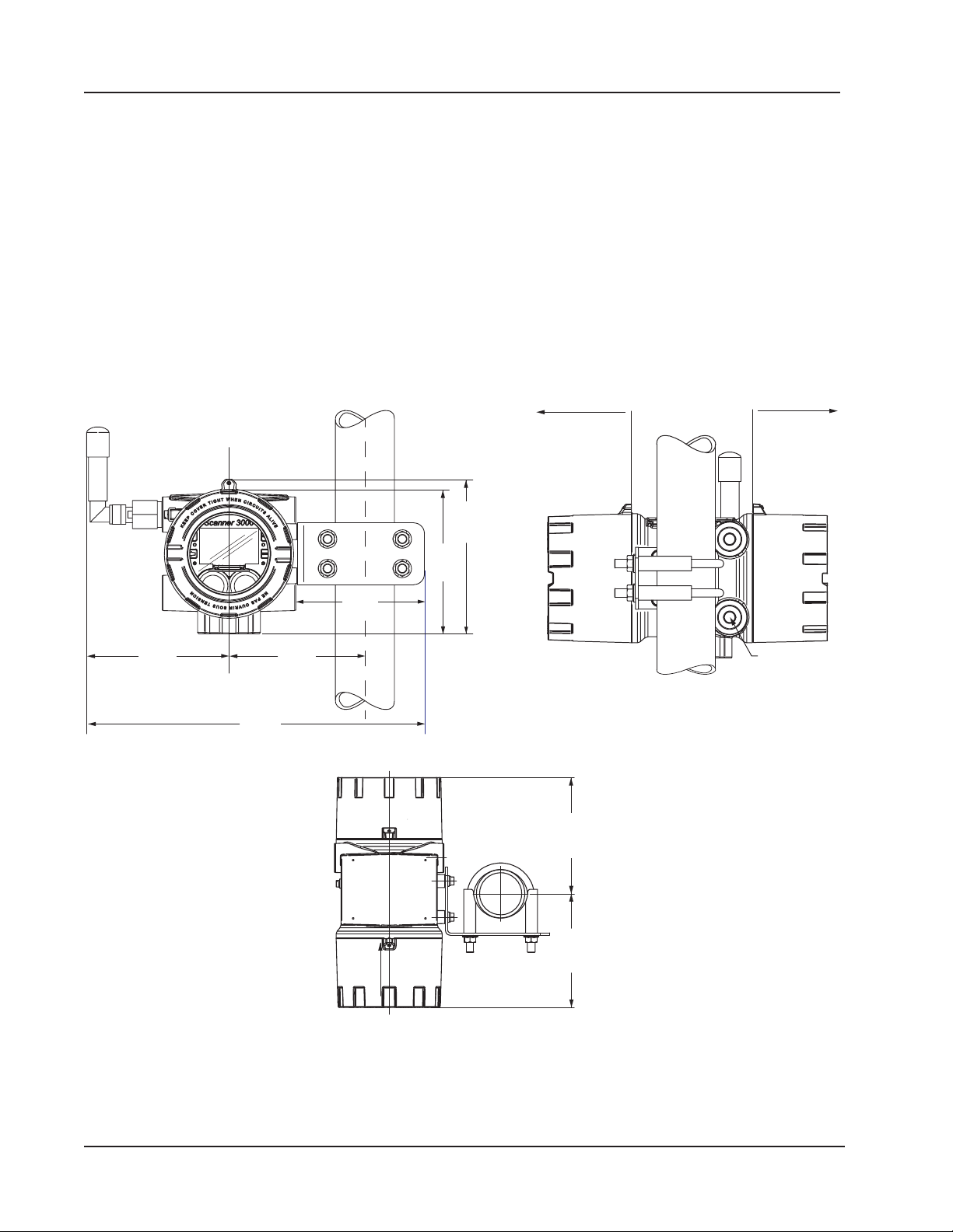
CSA Requirement: When using standard cable, a conduit seal
Accommodates
Section 2 Scanner 3100 EFM
The following accessories are also recommended:
• 5-valve manifold for connecting process lines to the MVT
• RTD assembly for process temperature input on gas ow runs and compensated liquid ow runs
• Tubing and/or pipe for plumbing process connections
• Explosion-proof signal cable for remote turbine connections (stranded, shielded cable is recommended)
Pole-Mounting the Scanner 3100
The 2-in. pole mount hardware kit (Figure 2.2) is a convenient option for remote-mounting the Scanner 3100. The kit
consists of a stainless steel “L” mounting bracket with four mounting holes, two U-bolts, four nuts, and four 10-mm M6
screws.
must be installed within 6 in. (152.4 mm) of the Scanner.
5.72
(145.2)
6.20
(157.5)
5.80
(147.2)
5.46
(138.7)
13.58
(344.8)
5.10
(129.7)
(back)
8.5
(216)
clearance
required
for removing
batteries
(front) (back)
5.70
(144.8)
approx
5.0
(127)
clearance
required
for accessing
terminals
straight
nipple/cable
radius up to
0.58 (14.73)
5.58
(141.8)
approx
(front)
Figure 2.2—Scanner 3100 remote-mounted with a 2-in. pole mount kit; dimensions are shown in inches (mm)
30
Page 31
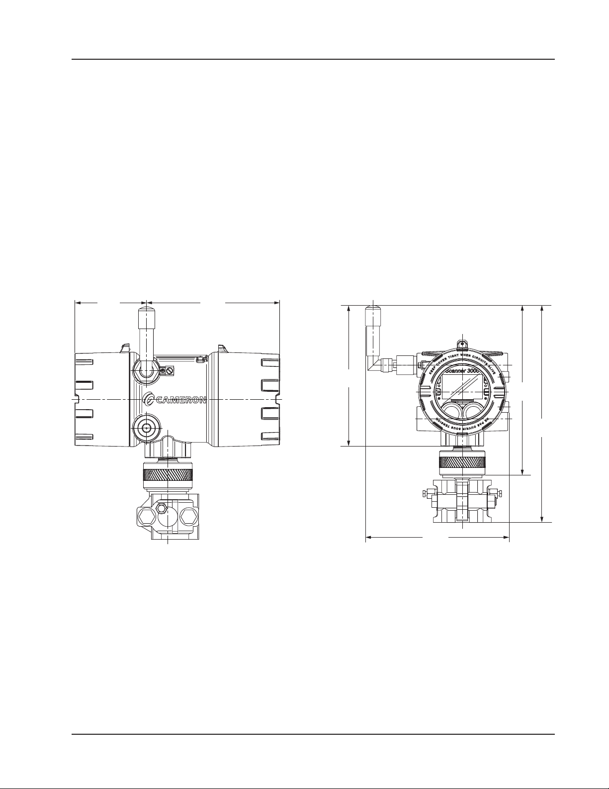
3.94
7.33
(215.18)
(324.95)
Scanner 3100 EFM Section 2
Install as follows:
1. Locate the mounting bosses on the side of the Scanner 3100 enclosure.
2. Attach the mounting bracket to the bosses using the four 10-mm screws provided. For best stability, orient the
bracket so that the at surface of the “L” bracket is near the front of the Scanner 3100.
3. Position the device with bracket against the pole so that the bracket is directly in front of the pole.
4. Install the two U-bolts around the pole and through the mounting holes in the bracket.
5. Tighten the U-bolts securely.
6. Install and connect process piping between the Scanner 3100 and the ow meter with appropriate ttings. Process
piping installation procedures vary with each application.
Hazardous Area Requirements for Wireless Communications
Each Scanner 3100 wireless device is equipped with a wireless module connected to the main circuit board and an
explosion-proof coupler that threads into an enclosure port. Antennas and antenna cable are optionally available. Figure
2.3 shows installation dimensions for a Scanner 3100 equipped with the direct-mount, right-angle antenna supplied by
Cameron.
(100.2)
Figure 2.3—Wireless Scanner 3100 with MVT and direct-mount antenna; dimensions are shown in in. (mm)
(186.11)
8.31
(211.13)
10.01
(254.31)
12.79
8.47
The installation of the antenna coupler, antennas, and antenna cable must meet the requirements shown in Figure 2.4 and
Figure 2.5, page 32.
Cameron supplies the following antenna and antenna cable options:
• Direct-mount, right-angle antenna with N male connector
• Remote-mount antenna with N female connector
• Type 400 male-to-male antenna cable in three lengths - 10, 20, and 30 feet
See Table 7.2—Wireless Components, page 88 for ordering details.
31
Page 32
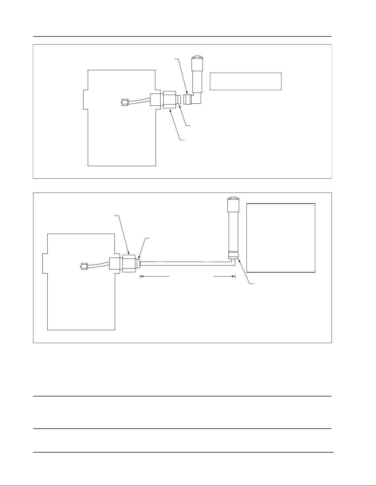
Section 2 Scanner 3100 EFM
N-MALE CONNECTOR
DIRECT-MOUNT ANTENNA
CONNECTS TO
WIRELESS
MODULE
INSIDE
SCANNER 3100
ENCLOSURE
N-FEMALE CONNECTOR
ANTENNA COUPLER (NO SEAL REQUIRED)
PART NO. 2350765-01 (CSA - NORTH AMERICA)
PART NO. 76533628 (ATEX)
PART NO. 2350869-01
HAZARDOUS AREA
Figure 2.4—Installation requirements for a direct-mount Cameron-supplied antenna
ANTENNA COUPLER (NO SEAL REQUIRED)
PART NO. 2350765-01 (CSA - NORTH AMERICA)
PART NO. 76533628 (ATEX)
CONNECTS TO
WIRELESS
MODULE
INSIDE
SCANNER 3100
ENCLOSURE
N-FEMALE CONNECTOR
MALE-TO-MALE CABLE
MAX. 30 FT (9.1 M)
(CSA - NORTH AMERICA)
MAX. CAPACITANCE: 60 pF/ft (196 pF/m)
MAX. INDUCTANCE: 2µH/ft (6.5 µH/m)
(ATEX)
MAX. CAPACITANCE: 23.9 pF/ft (78.4 pF/m)
MAX. INDUCTANCE: 0.060 µH/ft (0.20 µH/m)
REMOTE ANTENNA
PART NO. 50279275
OR EQUIVALENT DESIGN WITH
GAIN OF 10 dBI OR LESS
(CSA - NORTH AMERICA)
MAX. CAPACITANCE: 200 pF
MAX. INDUCTANCE: 100 nH
(ATEX)
MAX. CAPACITANCE: 50 pF
MAX. INDUCTANCE: 20 nH
N-FEMALE CONNECTOR
HAZARDOUS
AREA
Figure 2.5—Installation requirements for a remote-mount antenna
FCC Radio Frequency Compliance
Scanner 3100s that include the optional SmartMesh radio module comply with Federal Communications Commission
(FCC) radio frequency (RF) exposure compliance requirements when the following requirements are met.
Important To comply with FCC and IC RF exposure compliance requirements, the antenna must be installed
to provide a separation distance of at least 20 cm from all persons. Changes or modications to
the installation that violate this requirement and are not authorized by the radio manufacturer
could void your authority to operate the equipment.
32
Page 33
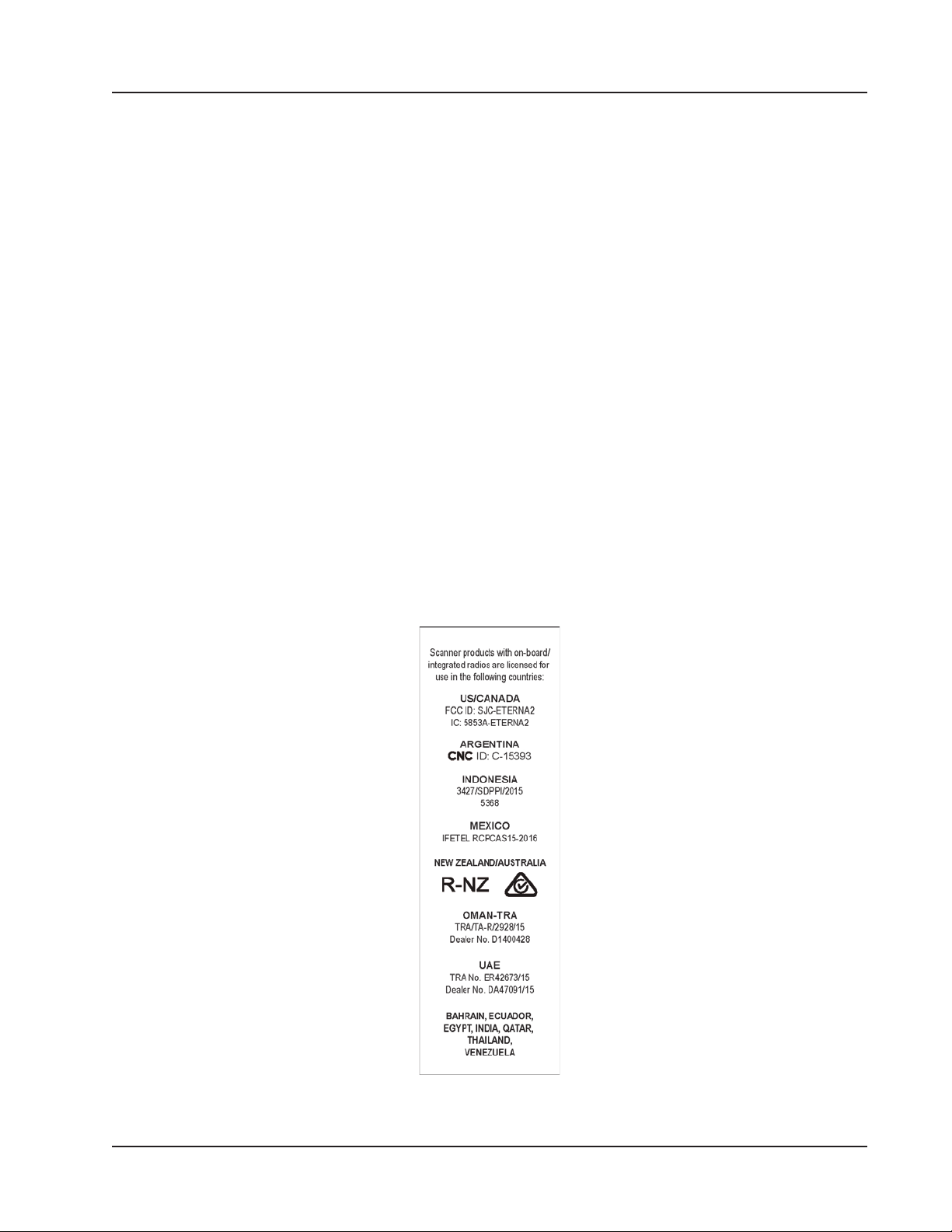
Scanner 3100 EFM Section 2
The SmartMesh radio has been tested and found to comply with the limits for a Class B digital device, pursuant to Part
15 of the FCC Rules. These limits are designed to provide reasonable protection against harmful interference in a residential installation. This equipment generates, uses and can radiate radio frequency energy and, if not installed and used
in accordance with the instructions, may cause harmful interference to radio communications. However, there is no
guarantee that interference will not occur in a particular installation. If this equipment does cause harmful interference to
radio or television reception, which can be determined by turning the equipment off and on, you are encouraged to try to
correct the interference by one or more of the following measures:
• Reorient or relocate the receiving antenna.
• Increase the separation between the equipment and receiver.
• Connect the equipment to an outlet on a circuit different from that used with the receiver.
• Consult the dealer or an experienced radio/TV technician for help.
IC Radio Frequency Compliance
Scanner 3100s that include the optional SmartMesh radio module comply with Industry Canada (IC) license-exempt RSS
standards. Operation is subject to the following conditions:
• The device may not cause interference.
• The device must accept any interference, including interference that may cause undesired operation of the device.
Radio Frequency Compliance Labeling
Scanner 3100s that include the optional SmartMesh radio module comply with a broad range of country-specic radio
frequency standards. The Scanner 3100 wireless radio is approved for use in all of the regions listed on a radio compliance label (Figure 2.6) applied to the Scanner 3100 enclosure.
Figure 2.6—Radio frequency compliance label applied to the Scanner 3100 enclosure (content may change without
notice)
33
Page 34
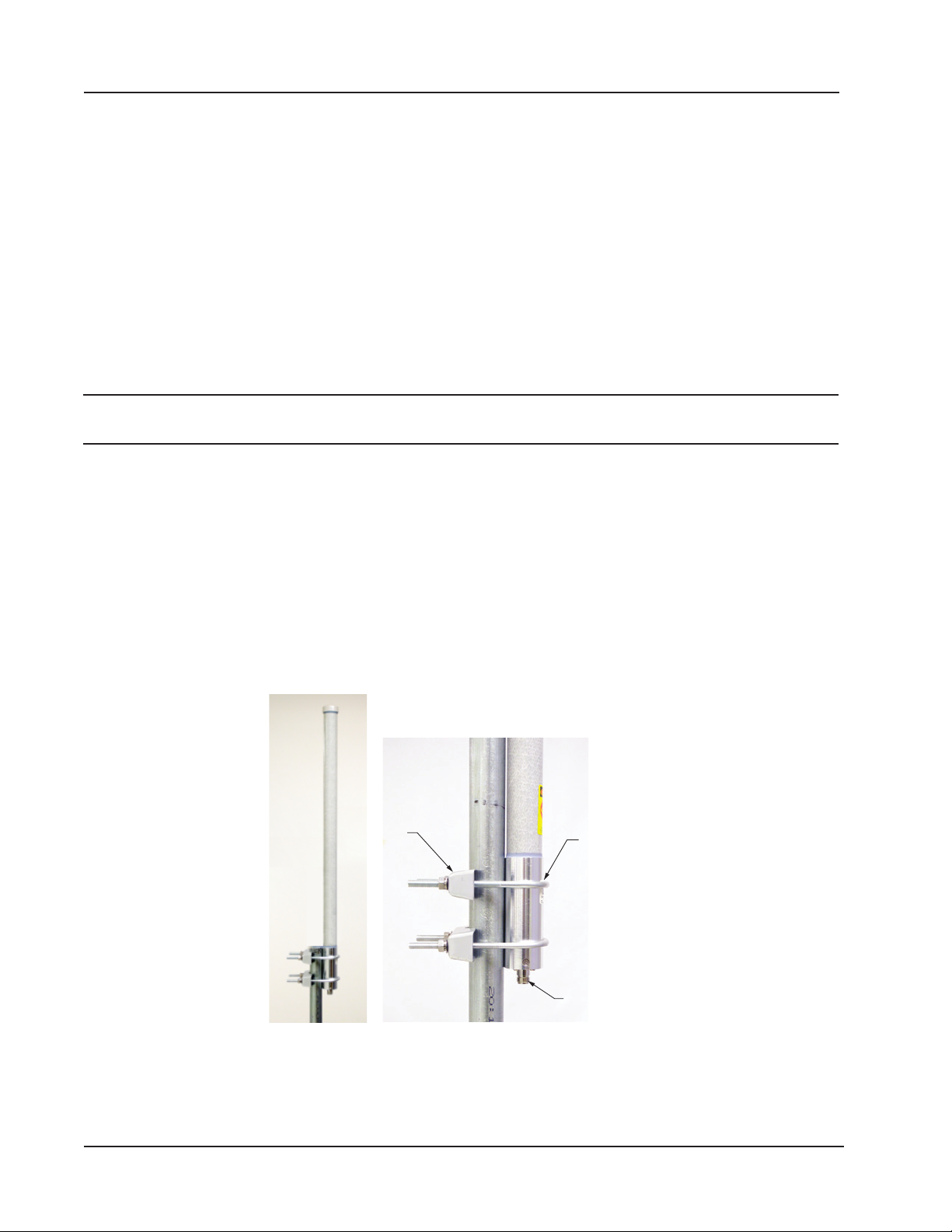
cable connector
Section 2 Scanner 3100 EFM
Antenna Installation Options
Direct-Mount Antenna
Each Scanner 3100 wireless device is equipped with a wireless module (installed on an advanced communications circuit
board) and an explosion-proof coupler that threads into an enclosure port. Antennas and antenna cable are optionally
available.
The installation of the antenna coupler, antennas, and antenna cable must meet the requirements shown in Figure 2.4 and
Figure 2.5, page 32.
Remote-Mount Antenna for Pole Outside Diameters up to 2 Inches
The standard hardware supplied with Cameron’s remote-mount antenna can be used to mount the antenna to a pole with
an outside diameter of 2 in. or less. The supplied hardware includes two U-bolts, two toothed brackets, four lock washers
and four nuts.
Note If a 2-in. pipe with a 2 3/8-in. outside diameter is to be used, consider using Cameron’s 2-in. pipe mount hard-
ware kit.
To install the antenna, reference Figure 2.7 while following the instructions below:
1. Position the antenna with the shiny metal base against a vertical pole and the capped end of the antenna vertical in
the air. Note the N-female cable connector at the bottom of the metal base for connecting antenna cable.
2. Position a U-bolt around the antenna and pole, placing the bend of the U-bolt against the antenna base.
3. Place a toothed bracket over the threaded legs of the U-bolt with the teeth facing the pole and slide the bracket
snugly against the pole.
4. Install a lock washer and a nut on each of the two U-bolt legs extending through the toothed bracket.
5. Repeat steps 2 through 4 to install the second U-bolt and toothed bracket to secure the base of the antenna.
6. Attach the antenna cable to the N-female cable connector at the bottom of the antenna.
Toothed
bracket
(2)
Figure 2.7—Standard pole mount bracket (ts poles with an outside diameter of 2 in. or less)
34
U-bolts (2)
N-female
Page 35
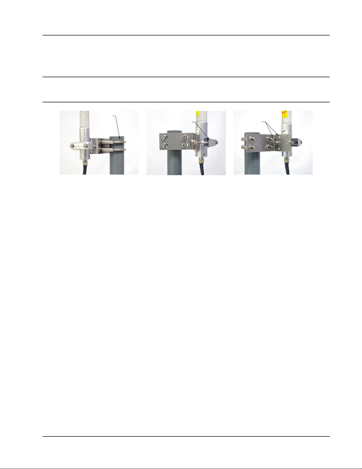
Scanner 3100 EFM Section 2
Remote-Mount Antenna for Pipe Outside Diameters of 2 3/8 Inches
Cameron’s optional pipe mount kit accommodates mounting the remote antenna to a 2-in. pipe with a 2 3/8-in. outside
diameter. The hardware kit includes a stainless steel L-shaped bracket, two U-bolts, four U-bolt nuts, two stainless steel
5/16-18 bolts (3.25-in. long), two 5/16-in. lock washers, two 5/16-in. at washers and two 5/16-in. nuts.
Important One of the toothed brackets shipped with the standard pole-mount kit is also required for this
installation. Do not discard the standard pole-mount kit antenna packaging before locating the
toothed brackets.
U-bolt (2) Toothed bracket
(ships with antenna)
Figure 2.8—Optional 2-in. pipe mount bracket
Top and bottom holes
are not used
To install the antenna, reference Figure 2.8 while following the instructions below:
1. Remove one of the toothed brackets from the standard pole-mount kit antenna packaging for use with the optional
hardware kit. The remaining hardware in the antenna package will not be used for this installation.
2. Position the L-shaped bracket against the pipe so that the pipe is on the outside of the “L” and secure it to the pipe
with the two U-bolts and four U-bolt nuts (Figure 2.8, left). The U-bolts will pass through the widest panel of the
“L” bracket.
3. Position the antenna against the bracket so that the shiny metal base is touching the bracket and the capped end of
the antenna is vertical in the air. Note the N-female cable connector at the bottom of the metal base for connecting
antenna cable.
4. Place the toothed bracket against the adjacent L-bracket panel (shortest of the two panels) so that the toothed, rounded edge faces the L-bracket panel and the holes in the toothed bracket align with the center holes in the L-bracket.
5. Place a at washer over each of the 5/16-in. bolts and insert the bolts through the holes in the toothed bracket and
through the center holes in the L-bracket panel (Figure 2.8, center and right).
6. Attach a lock washer and a nut to each of the bolts on the inside of the L-shaped bracket to hold the toothed bracket
loosely in place.
7. Position the antenna between the toothed bracket and the L-shaped bracket so that the rounded edge of the toothed
bracket ts snugly against the curvature of the shiny antenna base and the brackets clamp around the approximate
center of the antenna base.
8. Holding the antenna in place, tighten the two 5/16-in. nuts on the inside of the L-bracket to secure the antenna (Fig-
ure 2.8, right).
9. Attach the antenna cable to the N-female cable connector at the bottom of the antenna.
Industry Standard Compliance
To ensure measurement accuracy, ow runs and turbine meter runs must be installed in accordance with the industry
standards listed in Table 2.2—Industry Standards for Meter Installation, page 36. For a complete list of industry stan-
dards used in the development of ow rate and uid property calculations, see Table 1.4—Flow Rate Standards, page
23 and Table 1.5—Fluid Property and Energy Flow Calculations, page 24.
35
Page 36

Section 2 Scanner 3100 EFM
Table 2.2—Industry Standards for Meter Installation
Meter Type Standard Description
Orice Meter AGA 3, Section 2.6 Specications for orice meters (to include beta ratios)
Installation requirements for orice plates, meter tubes, ow conditioners, and
thermometer wells
This standard is also distributed under the following names: API MPMS Chapter
14.3, Part 2; ANSI/API 14.3, Part 2-3100; and GPA 8185, Part 2.
ISO 5167, Part 1 Installation of orice plates inserted into a circular cross-section conduit
running full
Limitation of pipe size and Reynolds number
ISO 5167 is applicable only to ow that remains subsonic throughout the
measuring section and where the uid can be considered single-phase. It is
not applicable to the measurement of pulsating ow. It does not cover the use
of orice plates in pipe sizes less than 50 mm (2 in.) or more than 1000 mm
(39 in.), or for pipe Reynolds numbers below 5000.
ISO 5167, Part 2 Species orice plates that can be used with ange pressure tappings, corner
pressure tappings, D and D/2 pressure tappings.
API MPMS Chapter
21.1, Section 1.7
API MPMS Chapter
21.1, Section 1.8
ASME M FC-14M Species low-ow orice meters smaller than 2 inch pipe size, that can be
Cone Meter NuFlo* Cone Meter
User Manual,
Sections 2 through 5
ISO 5167, Part 1 Installation of orice plates inserted into a circular cross-section conduit
Venturi Meter ISO 5167, Part 1 Installation of orice plates inserted into a circular cross-section conduit
ISO 5167, Part 3 ISO 5167-3 describes three Venturi meter variations: machined inlet, rough
Installation of electronic gas measurement devices and associated
communications, gauge/impulse lines, and cabling
Requirements for calibrating and verifying the accuracy of electronic gas
measurement devices
used with ange taps and corner taps.
Nominal pipe sizes (1/2 inch to 1-1/2 inch only)
Beta ratio from 0.1 to 0.75
Suitable for single-phase uids only
Subsonic ow only
Not suitable for pulsating ow
System components, impulse tubing considerations, best practices for
installation, installation procedures/diagrams for liquid and gas service
running full
Limitation of pipe size and Reynolds number
ISO 5167 is applicable only to ow that remains subsonic throughout the
measuring section and where the uid can be considered single-phase. It is
not applicable to the measurement of pulsating ow. It does not cover the use
of orice plates in pipe sizes less than 50 mm (2 in.) or more than 1000 mm
(39 in.), or for pipe Reynolds numbers below 5000.
running full
Limitation of pipe size and Reynolds number
ISO 5167 is applicable only to ow that remains subsonic throughout the
measuring section and where the uid can be considered single-phase. It is
not applicable to the measurement of pulsating ow. It does not cover the use
of orice plates in pipe sizes less than 50 mm (2 in.) or more than 1,000 mm
(39 in.), or for pipe Reynolds numbers below 5,000.
cast inlet, and welded sheet metal. Machined inlet meters are available in
diameters up to 10 inches (250 mm), rough cast meters up to 30 inches (800
mm), and welded construction up to 47 in. (1,200 mm).
36
Page 37
Scanner 3100 EFM Section 2
Table 2.2—Industry Standards for Meter Installation
Meter Type Standard Description
Turbi n e
Meter
AGA 7, Section 7 Installation of gas turbine meters to include ow direction, meter orientation,
meter run connections, internal surfaces, temperature well location, pressure
tap location, and ow conditioning
Illustrations of recommended installation congurations
Environmental considerations, the use of other devices to improve meter
performance, and precautionary measures
This specication applies to axial-ow turbine ow meters for measurement
of natural gas, typically 2-in. and larger bore diameter, in which the entire gas
stream ows through the meter rotor.
API MPMS Chapter
21.1, Section 1.7
API MPMS Chapter
21.1, Section 1.8
API MPMS 5,
Section 3
ISO 5167, Part 1 Installation of orice plates inserted into a circular cross-section conduit
Installation of electronic gas measurement devices and associated
communications, gauge/impulse lines, and cabling
Requirements for calibrating and verifying the accuracy of electronic gas
measurement devices
Description of unique installation requirements and performance
characteristics of turbine meters in liquid hydrocarbon service (This section
does not apply to the measurement of two-phase uids.)
running full
Limitation of pipe size and Reynolds number
ISO 5167 is applicable only to ow that remains subsonic throughout the
measuring section and where the uid can be considered single-phase. It is
not applicable to the measurement of pulsating ow. It does not cover the use
of orice plates in pipe sizes less than 50 mm (2 in.) or more than 1,000 mm
(39 in.), or for pipe Reynolds numbers below 5,000.
Measuring Natural Gas via a Differential Pressure Meter
Best Practices
For best measurement accuracy, ensure that the meter run complies with the following AGA 3 and ISO 5167 guidelines,
as applicable:
• Do not place unit near vents or bleed holes that discharge corrosive vapors or gases.
• Consider the orientation of the meter run when determining the best position for mounting the Scanner 3100.
– If the Scanner 3100 is mounted to a horizontal pipeline, make sure process connections are at the top of the line,
and mount the Scanner 3100 above the pressure connections at the pipe.
– If the Scanner 3100 is mounted to a vertical pipeline, install the sensor above the differential pressure source
connections, or install a condensate (drip) pot to prevent the accumulation of liquid in interconnecting tubes.
Slope all tubing upward at least 1 in./LF to avoid liquid entrapment.
• Mount the Scanner 3100 as near level as possible such that the operator has a clear view of the LCD and can access
the keypad easily when the enclosure cover is removed. The location should be as free from vibration as possible.
• Ensure the high port of the sensor (marked H) is connected to the upstream side of the meter run.
• Flow should remain subsonic throughout the measuring section and should be single phase.
• Pipe diameters (D) should be between 2 in. (50 mm) and 39 in. (1,000 mm) per ISO 5167; or greater than 2 in. (50
mm) per AGA 3.
• Pipe Reynolds numbers must be above 5,000.
• d (orice diameter) must be greater than or equal to 0.45 in. (11.5 mm).
37
Page 38
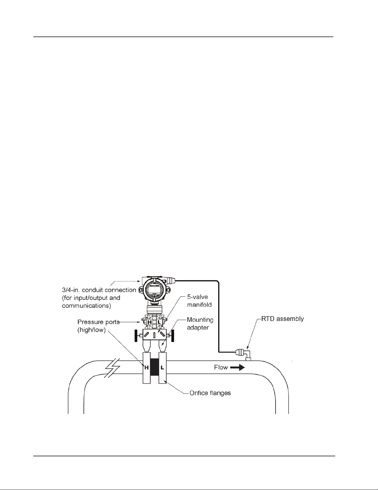
Section 2 Scanner 3100 EFM
• β (diameter ratio) must be greater than or equal to 0.1 and less than or equal to 0.75.
• Gauge lines should be of uniform internal diameter and constructed of material compatible with the uid being
measured. For most applications, the bore should be no smaller than 1/4 in. (6 mm) and preferably, 3/8 in. (10
mm) in diameter. The internal diameter should not exceed 1 in. (25 mm). If high-temperature uids are likely to be
encountered, make sure the measuring tube used is rated for the anticipated temperature range.
• Gauge line length should be minimized to help prevent pulsation-induced errors.
• Gauge lines should slope downward to the meter at a minimum of 1 in. per foot.
• If gauge lines must slope in more than one direction, do not allow more than one bend and install a liquid or gas
trap, as applicable. A liquid trap should be installed at the lowest point in a gas service installation.
• Gauge lines should be supported to prevent sag and vibration.
• Where pulsation is anticipated, full-port manifold valves with a nominal internal diameter consistent with the gauge
lines are recommended.
If the Scanner 3100 is mounted to a cone meter, consider the following best practices as well:
• Position the cone meter so that there are 0 to 5 diameters of straight pipe upstream of the meter and 0 to 3 diameters
of straight pipe downstream of the meter.
• Install the meter so that the static pressure tap is upstream of the differential pressure tap. The high side of the
integral Scanner 3100 sensor must also be situated upstream.
• Install shutoff valves directly on the pressure taps. Choose a shutoff valve that is rated for the ambient temperatures of
the location and the operating pressure of the pipe in which it will be installed, and suitable for use with dangerous or
corrosive uids or gases, if applicable. The valves must not affect the transmission of the differential pressure signal.
Direct Mount to Orice Meter or Cone Meter
A Scanner 3100 can be mounted directly to an orice meter or cone meter for gas measurement. The setup of the meter
run and plumbing congurations can vary widely, depending upon the challenges existing on location. Figure 2.9 shows
a typical direct-mount installation.
Figure 2.9—Direct-mount installation in an orice meter run. The direct-mount method can be used with a cone meter as
well.
38
Page 39
Scanner 3100 EFM Section 2
WARNING—HAZARDOUS AREA USE. The Scanner 3100 is certied for hazardous area use only when
1. Verify that the meter is properly installed in the ow line (per manufacturer’s instructions).
2. Bolt a ange-by-ange 5-valve manifold (as recommended by Cameron) to the Scanner 3100 MVT sensor.
3. Connect the Scanner 3100 and manifold assembly to the differential pressure meter. Hardware requirements will
CAUTION Do not use Teon tape on the threads of the union, adapter, or pipe plugs that may be installed in
installed in accordance with applicable standards and local wiring practices. Carefully review Hazardous
!
Area Precautions, page 27 to determine specic installation requirements (cable glands, conduit seals,
signal cable, RTD, etc.).
a. Locate the H and L markings on the MVT sensor body and position the MVT/manifold assembly so that the
upstream side of the ow line can easily be connected to the sensor’s “High” port and the downstream side of
the ow line can be connected to the sensor’s “Low” port. The Scanner 3100 enclosure can be rotated to face
the desired direction.
b. Position the manifold so that all valves are accessible from the front of the instrument.
vary, depending upon the installation conguration. Minimally, an adapter that can span between the threaded pressure tap/orice ange connector and the non-threaded manifold is required. This adapter can be a one-piece stabilizer (often preferred for added strength and stability) or a short heavy-wall pipe nipple attached to a football ange
(available from Cameron). Use a suitable compound or tape on all threaded process connections.
the enclosure. Use of Teon tape will void the explosion-proof rating of the instrument.
4. Install the RTD assembly in the thermowell. Route the RTD assembly cable through a conduit opening in the top
of the Scanner 3100 to connect to the terminal board. A wiring diagram for the RTD assembly is provided in Figure
3.6, page 59. For hazardous areas, review Hazardous Area Precautions, page 27.
5. Route any additional inputs/outputs or COM connections, etc. through a conduit opening in the top of the Scanner
3100. For hazardous areas, review Hazardous Area Precautions, page 27.
6. Perform a manifold leak test as described in Performing a Manifold Leak Test, page 51.
7. Verify the zero offset, if required (and other calibration points, if desired). See the Scanner 3100 Web Interface User
Manual for complete instructions. See also Zero Offset (Static Pressure or Differential Pressure), page 51, Differ-
ential Pressure Calibration and Verication, page 53, and Static Pressure Calibration and Verication, page 52.
CAUTION Do not put the Scanner into operation until the valves are positioned properly so that pressure is
supplied to both sides of the MVT. For instructions on proper valve positions, see Placing the Scan-
ner into Operation, page 54.
Remote Mount to Orice Meter or Cone Meter
A Scanner 3100 can be mounted remotely and connected to an orice meter or cone meter with tubing for gas measurement. The setup of the meter run and plumbing congurations can vary widely, depending upon the challenges existing
on location. Figure 2.10, page 40 shows a typical remote-mount gas run installation.
WARNING—HAZARDOUS AREA USE. The Scanner 3100 is certied for hazardous area use only when
!
installed in accordance with applicable standards and local wiring practices. Carefully review Hazardous
Area Precautions, page 27 to determine specic installation requirements (cable glands, conduit seals,
signal cable, RTD, etc.).
Note To prevent ttings from turning and to avoid putting tension on stainless steel tubing, use a backup wrench to at-
tach stainless steel tubing to a manifold, shutoff valves, or sensor ports.
39
Page 40
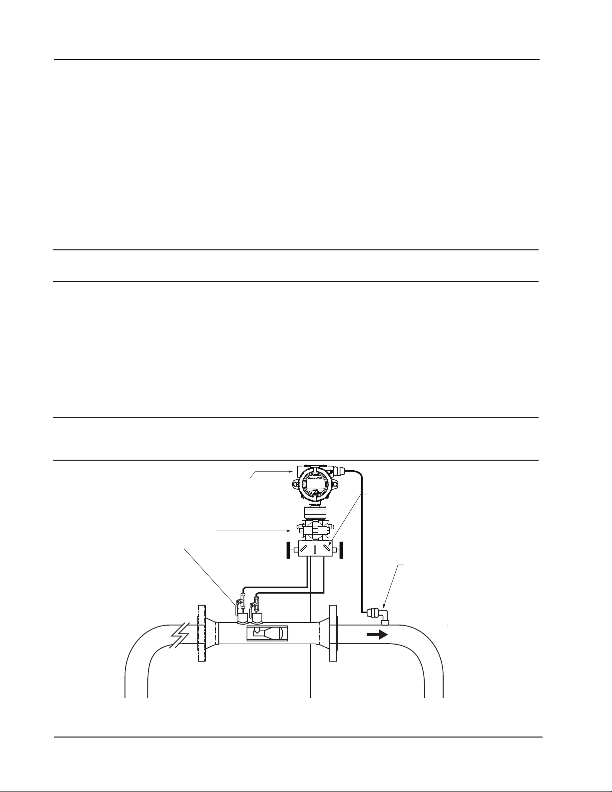
RTD assembly
Section 2 Scanner 3100 EFM
1. Verify that the meter is properly installed in the ow line (per manufacturer’s instructions).
2. Mount the Scanner 3100 to a 2-in. pipe using the mounting bosses on the side of the enclosure and a Cameron pole
mount kit. See Pole-Mounting the Scanner 3100, page 30 for detailed mounting instructions.
3. Bolt a 5-valve ange-by-NPT manifold (as recommended by Cameron) to the Scanner 3100 MVT sensor.
a. Locate the H and L markings on the integral MVT sensor body and position the MVT/manifold assembly so
that the upstream side of the ow line can easily be connected to the sensor’s “High” port and the downstream
side of the ow line can be connected to the sensor’s “Low” port. The Scanner 3100 enclosure can be rotated to
face the desired direction.
b. Position the manifold so that all valves are accessible from the front of the instrument.
4. Install tubing and ttings to connect the Scanner 3100 and manifold assembly to the differential pressure meter,
sloping the gauge lines downward to the meter at a minimum of one inch per foot. Use a suitable compound or tape
on all threaded process connections.
CAUTION Do not use Teon tape on the threads of the union, adapter, or pipe plugs that may be installed in
the enclosure. Use of Teon tape will void the explosion-proof rating of the instrument.
5. Install the RTD assembly in the thermowell. Route the RTD assembly cable through a conduit opening in the top
of the Scanner 3100 to connect to the terminal board. A wiring diagram for the RTD assembly is provided in Figure
3.6, page 59. For hazardous areas, review Hazardous Area Precautions, page 27.
6. Route any additional inputs/outputs or COM connections, etc. through a conduit opening in the top of the Scanner
3100. For hazardous areas, review Hazardous Area Precautions, page 27.
7. Perform a manifold leak test as described in Performing a Manifold Leak Test, page 51.
8. Verify the zero offset (if required) and other calibration points (if desired). See the Scanner 3100 Web Interface User
Manual for complete instructions. See also Zero Offset (Static Pressure or Differential Pressure), page 51, Differ-
ential Pressure Calibration and Verication, page 53, and Static Pressure Calibration and Verication, page 52.
CAUTION Do not put the Scanner into operation until the valves are positioned properly so that pressure is
supplied to both sides of the MVT. For instructions on proper valve positions, see Placing the Scan-
ner into Operation, page 54.
3/4-in. conduit connection
(for input/output and
communications)
Pressure ports
(high/low)
L
H
Figure 2.10—Remote-mount gas cone meter run installation. The remote-mount method can be used with an orice meter
as well.
L
H
Manifold
Flow
40
Page 41

Scanner 3100 EFM Section 2
Measuring Natural Gas via a Turbine Meter
Best Practices
The Scanner 3100 calculates gas ow through a turbine meter in accordance with AGA 7 and API MPMS Chapter 21.1
industry standards. For optimum performance, ensure that the turbine and Scanner 3100 installation complies with the
industry recommendations listed below:
• Install the turbine owmeter in the meter run such that there are 10 nominal diameters of straight pipe upstream
and 5 nominal diameters of straight pipe downstream of the meter. Both inlet and outlet pipe should be of the same
nominal size as the meter.
• Straightening vanes are recommended for eliminating swirl conditions. If used, they should be installed 5 diameters
of straight pipe upstream of the meter.
• Where an RTD is used to facilitate compensated gas measurement from a gas turbine meter, locate the RTD within 5
diameters of straight pipe downstream of the meter outlet and upstream of any valve or ow restriction.
Remote Mount to a Turbine Meter
A Scanner 3100 can be mounted remotely and connected to a gas turbine meter for measuring gas in accordance with
AGA 7 calculations. Figure 2.11, page 42 shows an installation in which the pressure input is provided by the integral
MVT. The setup of the meter run and plumbing congurations can vary widely, depending upon the challenges existing
on location.
WARNING—HAZARDOUS AREA USE. The Scanner 3100 is certied for hazardous area use only when
!
To connect the Scanner 3100 to a turbine meter, perform the following steps:
1. Verify that the owmeter and magnetic pickup are installed in the ow line.
2. Mount the Scanner 3100 to a 2-in. pipe using the mounting bosses on the side of the enclosure and a Cameron pole
3. Bolt a 3-valve ange-by-NPT manifold (as recommended by Cameron) to the Scanner 3100 MVT sensor. Position
4. Connect the pressure port of the turbine meter to either manifold process port with tubing. The unused pressure port
CAUTION Do not use Teon tape on the threads of the union, adapter, or pipe plugs that may be installed in
5. Remove the plug from the conduit opening in the top of the Scanner 3100 enclosure, route the turbine signal cable
6. Install the RTD assembly in the thermowell. Remove the plug from the other conduit opening in the top of the Scan-
7. Zero the static pressure and recalibrate, if required. See the Scanner 3100 Web Interface User Manual for complete
installed in accordance with applicable standards and local wiring practices. Carefully review Hazardous
Area Precautions, page 27 to determine specic installation requirements (cable glands, conduit seals,
signal cable, RTD, etc.).
mount kit. See Pole-Mounting the Scanner 3100, page 30 for detailed mounting instructions.
the manifold so that all valves are accessible from the front of the instrument.
can be used as a “vent” as required. Always leave the equalizer valves open to allow pressure to both sides of the
MVT. Use a suitable compound or tape on all threaded process connections.
the enclosure. Use of Teon tape will void the explosion-proof rating of the instrument.
through the opening, and connect it to the terminal board. A wiring diagram for the turbine input is provided in Fig-
ure 3.7, page 60. For hazardous areas, review Hazardous Area Precautions, page 27.
ner 3100 enclosure, route the RTD assembly cable through the conduit opening in the top of the Scanner 3100, and
connect it to the terminal board. A wiring diagram for the RTD assembly is provided in Figure 3.6, page 59. For
hazardous areas, review Hazardous Area Precautions, page 27.
instructions. See also Zero Offset (Static Pressure or Differential Pressure), page 51, Differential Pressure Calibra-
tion and Verication, page 53, and Static Pressure Calibration and Verication, page 52.
41
Page 42
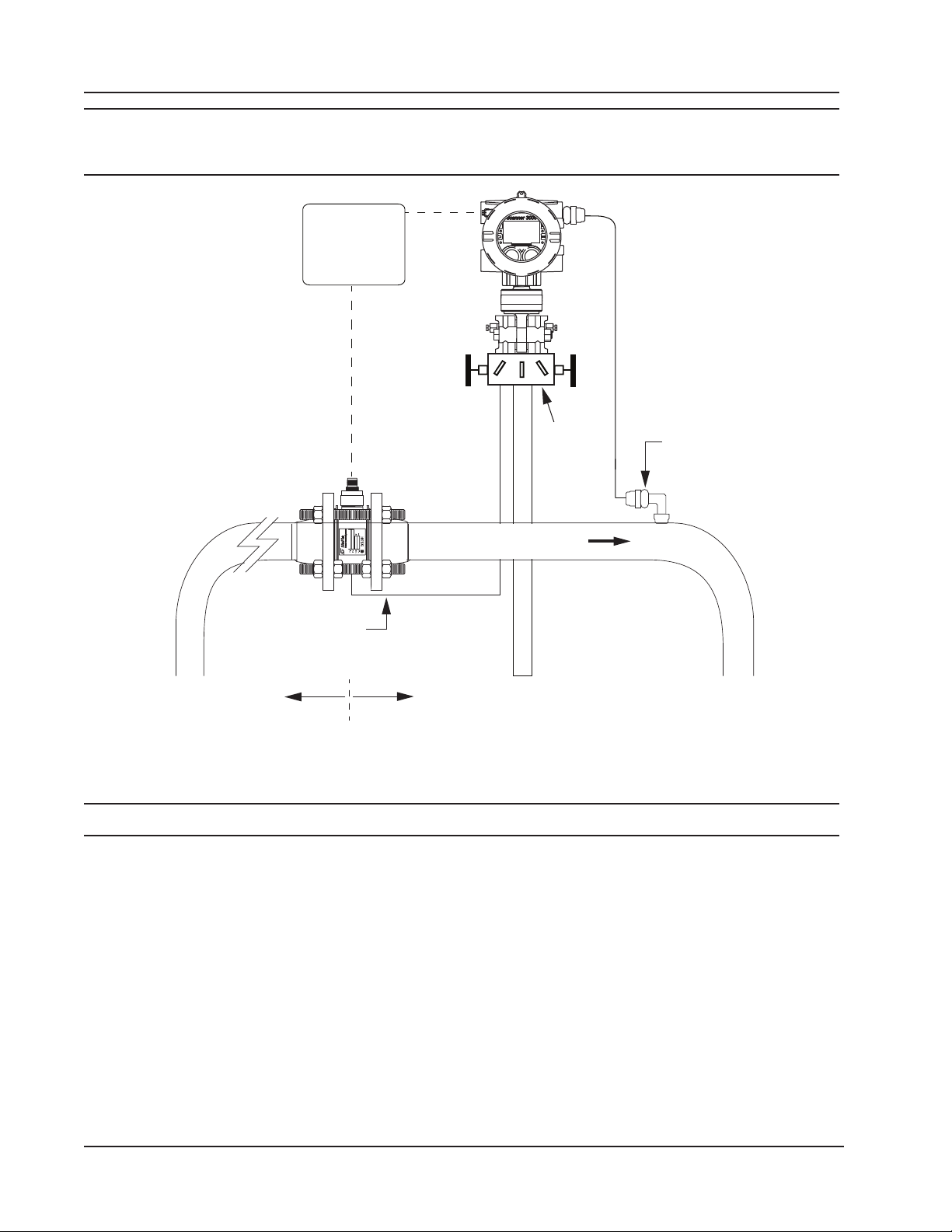
10 pipe diameters
upstream
downstream
Section 2 Scanner 3100 EFM
CAUTION Do not put the Scanner into operation until the valves are positioned properly so that pressure is
supplied to both sides of the MVT. For instructions on proper valve positions, see Placing the Scan-
ner into Operation, page 54.
Seal cable at point of
entry in accordance
with the relevant
code of practice
Manifold
Flow
Static pressure input
(manifold equalizer
valve must remain open)
5 pipe diameters
Figure 2.11—Remote-mount installation in an AGA 7 turbine meter run
RTD
assembly
Measuring Steam via a Differential Pressure Meter
Note Steam uid types are only supported for ow rate calculation methods using orice meters or cone meters.
Best Practices
The Scanner 3100 calculates steam ow in accordance with IF-97, AGA-3, and ISO-5167 industry standards. For optimum performance, ensure that the installation complies with the following industry recommendations:
Condensate Pots
• A condensate pot for a small-volume transducer like the Scanner 3100 MVT can be a simple pipe tee, oriented so
• The pots should be the highest point in the system.
• The pots should be mounted at the same level, and one or both should be adjustable vertically to remove zero shifts in
42
that one port extends downward (into the cold leg), the opposite port extends upward and is closed by a pipe cap or
blowdown valve, and the tee extends horizontally into the hot leg.
the differential pressure measurement.
Page 43

Scanner 3100 EFM Section 2
Hot Legs
• Hot legs should be large diameter (1/2 in. recommended)
• Hot legs should be as short as possible. If these sections must be more than 1ft in length, insulate them.
• Elbows and bends should not form any traps in which liquid can accumulate.
• Hot legs should be sloped along their entire length to allow liquids to drain back into the pipe.
Cold Legs
• Cold legs should enter the multi-variable sensor through its bottom ports. Side port installation is also available.
Contact your sales representative or technical support for assistance with side port installation.
• Cold legs should not be insulated and should be a minimum of 2 ft in length to allow proper convection cooling of
the process uid to below 120 degF. The nominal rate of cooling is 100 degF/ft, with an ambient temperature of 70
degF.
• If the cold leg must be installed horizontally, ensure a slope of approximately 1 in./ft to allow air bubbles to oat up
into the pots.
• Elbows and bends should not form any traps for air bubbles.
• Cold legs should be lled with a suitable antifreeze. Dibutyl phthalate is recommended.
Antifreeze
Dibutyl phthalate (DBP) has the following advantages over glycol antifreeze:
• Does not mix with water, and therefore does not become dilute over time; its specic gravity does not shift.
• It is slightly denser than water, so it will stay in the pot permanently.
• It is non-ammable.
• It is much less toxic than glycol.
• It is available from industrial suppliers.
Valves
• Use only full-opening block valves that are rated for steam service.
• Use only blowdown valves rated for steam service. Periodic blowdowns are recommended to prevent scale build up.
CAUTION Before starting the system, remove the caps and add water or antifreeze if necessary to completely
ll the pots and cold legs. Air trapped in the lines will produce errors in differential pressure measurements.
WARNING: EXPLOSION RISK. Housing temperature must not exceed 70 degC (158 degF). Excessive tem-
peratures, which could result from ambient conditions combined with radiated and conductive heat from
!
the process, could cause the internal lithium battery to ignite or explode.
Installation Procedure—Remote Mount to Orice Meter or Cone Meter
A Scanner 3100 can be mounted remotely and connected to an orice meter or cone meter with tubing for steam measurement. The setup of the meter run and plumbing congurations can vary widely, depending upon the challenges existing on location.
43
Page 44
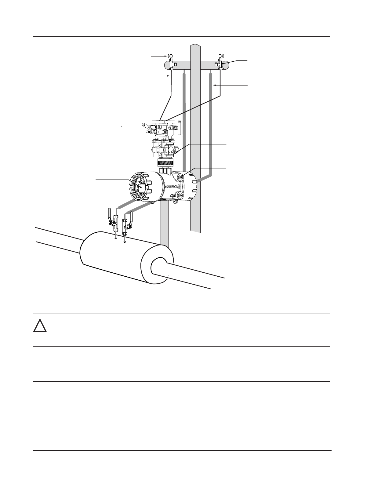
(1/2 in. diameter recommended)
Section 2 Scanner 3100 EFM
Pipe tee (can be used to fill cold legs)
Long cold legs protect the sensor from
extreme process temperatures
Cold legs connect to manifold
(slope to eliminate air trap)
LCD orientation
auto-corrects when
device is inverted
Condensate pot (pipe tee
with blowdown valve attached)
Hot legs, insulated to within
1 ft of condensate pot
MVT vent (can be used to fill cold legs)
3/4 in. conduit connection for
input/output & communications
Figure 2.12—Remote-mount steam run installation
WARNING: HAZARDOUS AREA USE. The Scanner 3100 is certied for hazardous area use only when
installed in accordance with applicable standards and local wiring practices. Carefully review
!
Hazardous Area Precautions, page 27, to determine specic installation requirements (cable glands, con-
duit seals, signal cable, RTD, etc.).
IMPORTANT When measuring steam, process connections must be designed to eliminate air pockets. This is
achieved by making sure all tubing in the cold legs slopes upward. A bottom-port MVT and block
manifold (shown in Figure 2.12) is recommended to help prevent air bubbles from being
trapped in the sensor.
1. Verify that the meter is properly installed in the ow line (per manufacturer’s instructions).
2. Mount the Scanner 3100 to a 2-in. pipe or to a at, vertical surface using bolts and the mounting holes in the enclosure. A horizontal pipe is recommended, as additional hardware may be required for a vertical pipe mount to provide
clearance for the manifold block.
44
Page 45

Scanner 3100 EFM Section 2
3. Mount a set of pipe tees (which serve as condensate pots) typically on either side of the Scanner 3100 at an elevation
above the process connections of the Scanner 3100 MVT (for proper drainage). They should be a considerable distance (see Best Practices, page 42) from the sensor ports, but as close as possible to the pressure taps on the meter.
4. Install a pipe cap or a blowdown valve that is rated for steam service at the top of each pipe tee. A blowdown valve
is recommended when the steam passing through the meter is known to be dirty.
5. Install tubing and ttings to connect the high-pressure and low-pressure taps of the DP meter to the pipe tees. This
section is typically referred to as the hot legs of the installation, as this section of tubing encounters steam at its
highest temperature. Install a shut-off valve near the high and low ports of the DP meter. Use a suitable compound or
tape on all threaded process connections.
6. Route any additional inputs/outputs or COM connections, etc. through the conduit opening in the side of the Scanner
3100. For hazardous areas, review Hazardous Area Precautions, page 27.
Note To prevent ttings from turning and/or to avoid putting tension on stainless steel tubing, use a backup wrench to
attach stainless steel tubing to shut-off valves or sensor ports.
CAUTION Whenever possible, locate the hot legs of a steam installation behind the Scanner 3100 safely out
of the operator’s normal reach. This will help prevent accidental burns.
7. Install tubing to connect the high-pressure and low-pressure process connections of the block manifold to the pipe
tees installed in step 3. This tubing section is typically referred to as the cold legs of the installation, since it is lled
with water.
8. To eliminate air bubbles, ll the cold legs with water or other ll uid from the lowest point in the system, typically
the MVT, using the following steps:
a. Open the blowdown valve or remove the lling plug from one of the pipe tees/condensate pots.
b. Open the equalizer and bypass/block valves on the block manifold. Ensure the vent valve is closed.
c. Remove the corresponding (high pressure or low pressure) vent screw from the side of the MVT and insert a
tting to allow connection of a hand pump or funnel. If a funnel is used, attach a length of Tygon tubing that is
long enough to elevate the funnel well above the condensate pot to force the uid up the legs.
d. Connect a hand pump or funnel to the tting.
e. Pour ll liquid into the funnel or pump it into the cold leg, tapping the cold leg occasionally to dislodge any
bubbles.
f. Observe the pipe tee/condensate pot and stop pouring when the ll liquid is visible at the top and no air bubbles
can be seen.
g. Remove the tting from the vent of the MVT and quickly replace the vent screw and tighten.
h. Close the blowdown valve or replace the lling plug from one of the pipe tees/condensate pots.
i. Repeat steps a through h for the other cold leg.
9. To eliminate an offset of the differential pressure reading, open the equalizer valves on the block manifold, remove
the caps from the seal pots, and adjust either seal pot vertically to bring the water levels to the exact same elevation.
10. Perform a manifold leak test as described on page 51.
11. Verify the zero offset, if required (and other calibration points, if desired). See the Scanner 3100 Web Interface User
Manual for complete instructions. See also Zero Offset (Static Pressure or Differential Pressure), page 51, Static
Pressure Calibration and Verication, page 52, and Differential Pressure Calibration and Verication, page 53.
IMPORTANT Do not put the Scanner into operation until the valves are positioned properly so that pressure is
supplied to both sides of the MVT. For instructions on proper valve positions, see
Placing the Scanner into Operation, page 54.
45
Page 46

Section 2 Scanner 3100 EFM
Measuring Liquid via a Differential Pressure Meter
Best Practices
To ensure measurement accuracy, ensure that the meter run complies with the following AGA 3 and ISO 5167 guidelines, as applicable:
• Do not place unit near vents or bleed holes that discharge corrosive vapors or gases.
• Consider the orientation of the meter run when determining the best position for mounting the Scanner.
– If the Scanner 3100 is mounted to a horizontal pipeline, make sure process connections are horizontal with
the pipeline, or sloped downwards towards the Scanner. Mount the Scanner 3100 below the pressure taps at
the pipe. Use the side (upper) ports as process connections and the bottom ports for draining and lling the
differential pressure housings.
– If the Scanner 3100 is mounted to a vertical pipeline, install the sensor below the differential pressure source
connections. Slope all tubing downward at least 1 in./LF to avoid gas entrapment.
• Mount the Scanner 3100 as near level as possible such that the operator has a clear view of the LCD, and can access
the keypad easily when the enclosure cover is removed. The location should be as free from vibration as possible.
• Make sure the high port of the sensor (marked “H”) is connected to the upstream side of the meter run.
• Pipe diameters (D) should be between 2 in. (50 mm) and 39 in. (1000 mm) per ISO 5167; or greater than 2 in. (50
mm) per AGA 3.
• Pipe Reynolds numbers must be above 5000. Avoid high-viscosity liquids (greater than 15 cP).
• d (orice diameter) must be greater than or equal to 0.45 in. (11.5 mm).
• Orice β (diameter ratio) must be greater than or equal to 0.1 and less than or equal to 0.75.
• Gauge lines should be of uniform internal diameter and constructed of material compatible with the uid being
measured. For most applications, the bore should be no smaller than 1/4 in. (6 mm) and preferably, 3/8 in. (10
mm) in diameter. The internal diameter should not exceed 1 in. (25 mm). If high-temperature uids are likely to be
encountered, make sure the measuring tube used is rated for the anticipated temperature range.
• If there is possibility of freezing, the gauge lines can be lled with a suitable seal liquid. The seal liquid should be
somewhat denser than the process uid, should not dissolve in it, should have a sufciently low freezing point, and
should be non-toxic. Alternatively, heat tracing can be used.
• Gauge line length should be minimized to help prevent pulsation-induced errors.
• Gauge lines should slope upward to the meter at a minimum of 1 in./ft.
• If gauge lines must slope in more than one direction, do not allow more than one bend and install a gas trap.
• Gauge lines should be supported to prevent sag and vibration.
• Where pulsation is anticipated, full-port manifold valves with a nominal internal diameter consistent with the gauge
lines are recommended.
If the Scanner 3100 is mounted to a cone meter, consider the following guidelines in addition to the best practices listed
above.
• Position the cone meter so that there are 0 to 5 diameters of straight pipe upstream of the meter and 0 to 3 diameters
of straight pipe downstream of the meter.
• Install the meter so that the static pressure tap is upstream of the differential pressure tap. The high side of the
integral Scanner 3100 sensor must also be situated upstream.
• Install shutoff valves directly on the pressure taps. Choose a shutoff valve that is rated for the ambient temperatures
of the location and the operating pressure of the pipe in which it will be installed, and for use with dangerous or
corrosive uids or gases, if applicable. The valves must not affect the transmission of the differential pressure signal.
46
Page 47

Scanner 3100 EFM Section 2
Direct Mount to Orice Meter or Cone Meter
A Scanner 3100 can be mounted directly to an orice meter or cone meter for liquid measurement using a side-port
MVT, a block manifold and two football ange adapters (Figure 2.13, page 48). The setup of the meter run and plumbing congurations can vary widely, depending upon the challenges existing on location.
CAUTION When measuring liquid with a direct-mount Scanner 3100, process connections must be parallel to
the horizontal center line of the meter, or below the center line to eliminate air pockets.
1. Verify that the meter is properly installed in the ow line (per manufacturer’s instructions).
2. Screw a football ange adapter onto each meter pressure tap using pipe tape or pipe dope to seal the threads.
3. Align the bolt holes in the Scanner 3100 MVT and manifold, and install bolts to mate these components to the foot-
ball anges, using O-rings as appropriate. Torque the bolts to the manufacturer’s specication.
4. Route any additional inputs/outputs, communications connections, etc. through a conduit opening in the top of the
Scanner 3100. For hazardous areas, review Hazardous Area Precautions, page 27.
5. Verify that all manifold valves are closed and ll the meter with process uid.
6. Loosen one of the vent screws in the side of the MVT.
7. Open the equalizer valves and the vent valve on the manifold.
8. Slowly open one of the bypass/block valves on the manifold. Process uid should immediately spurt from the MVT
vent.
9. When air bubbles are no longer visible around the MVT vent, tighten the MVT vent screw.
10. Loosen the other vent screw in the side of the MVT, and repeat steps 7 through 9.
11. Perform a manifold leak test as described in Performing a Manifold Leak Test, page 51.
12. Verify the zero offset (if required) and other calibration points (if desired). See the Scanner 3100 Web Interface User
Manual for complete instructions. See also Zero Offset (Static Pressure or Differential Pressure), page 51, Differ-
ential Pressure Calibration and Verication, page 53, and Static Pressure Calibration and Verication, page 52.
CAUTION Do not put the Scanner into operation until the valves are positioned properly so that pressure is
supplied to both sides of the MVT. For instructions on proper valve positions, see Placing the Scan-
ner into Operation, page 54.
47
Page 48
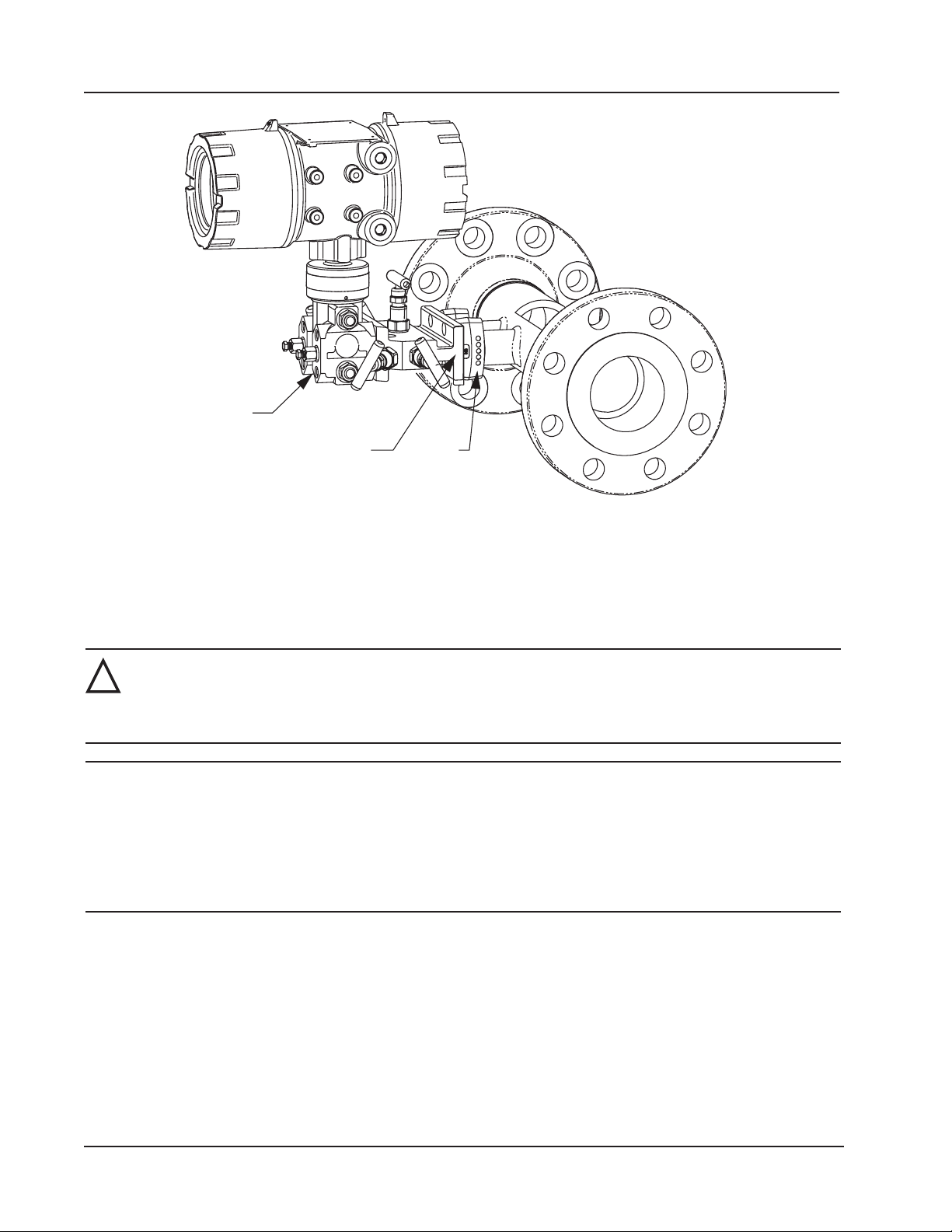
Section 2 Scanner 3100 EFM
MVT with
side ports
Block
manifold
Figure 2.13—Direct-mount liquid cone meter run installation. The downstream RTD is not shown.
Adapter
(2 typ.)
Remote Mount to Orice Meter or Cone Meter
A Scanner 3100 can be mounted remotely and connected to an orice meter or cone meter with tubing for liquid measurement (Figure 2.14, page 49). The setup of the meter run and plumbing congurations can vary widely, depending
upon the challenges existing on location.
WARNING—HAZARDOUS AREA USE. The Scanner 3100 is certied for hazardous area use only when
!
CAUTION When measuring liquid, process connections must be designed to eliminate air pockets. This is
1. Verify that the meter is properly installed in the ow line (per manufacturer’s instructions).
2. Mount the Scanner 3100 to a 2-in. pipe using the mounting bosses on the side of the enclosure and a Cameron pole
3. Install tubing and ttings to connect the high-pressure and low-pressure taps of the differential pressure meter to the
installed in accordance with applicable standards and local wiring practices. Carefully review Hazardous
Area Precautions, page 27 to determine specic installation requirements (cable glands, conduit seals,
signal cable, RTD, etc.).
achieved by mounting the sensor below the metering device and sloping all tubing downward from
the meter to the sensor. A side-port MVT and block manifold (shown in Figure 2.14, page 49) is
recommended to help prevent air bubbles from being trapped in the sensor.
If a bottom-port MVT is used, the bottom process ports must be plugged or replaced with a drain
valve, and side vents must be used for process connections. A block manifold is not recommended
for use with bottom port MVTs. Contact a Cameron eld representative for assistance.
mount kit. See Pole-Mounting the Scanner 3100, page 30 for detailed mounting instructions.
process connections of the block manifold. Install a pair of shutoff valves near the high and low ports of the differential pressure meter. Use a suitable compound or tape on all threaded process connections.
48
Page 49
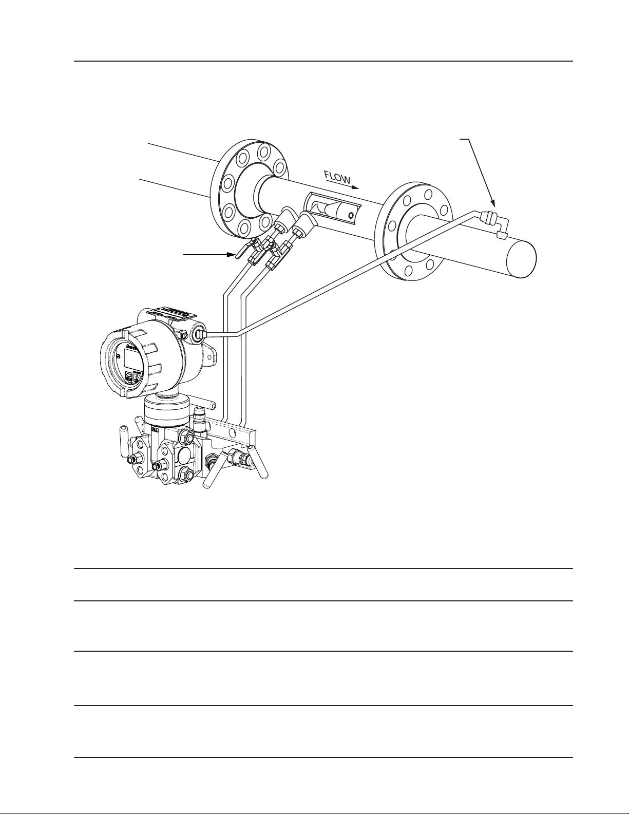
Scanner 3100 EFM Section 2
4. Install the RTD assembly in the thermowell. Remove the plug from a conduit opening in the top of the Scanner 3100
enclosure, route the RTD assembly cable through the conduit opening and connect it to the terminal board. A wiring
diagram for the RTD assembly is provided in Figure 3.6, page 59. For hazardous areas, review Hazardous Area
Precautions, page 27.
RTD assembly
Shut-off valves
throttle flow to
the manifold
and MVT
Positioning of sensor below the
meter and slope of tubing helps
prevent gas bubbles from entering
the liquid
Figure 2.14—Remote-mount liquid cone meter run installation. The remote-mount method can be used with an orice
meter as well.
5. Route any additional inputs/outputs, communications connections, etc. through a conduit opening in the top of the
Scanner 3100. For hazardous areas, review Hazardous Area Precautions, page 27.
Note To prevent ttings from turning and/or to avoid putting tension on stainless steel tubing, use a backup wrench to
attach stainless steel tubing to shutoff valves, or sensor ports.
6. To eliminate air bubbles in the MVT, manifold and legs connecting them to the meter, ll the legs with uid. Choose
a uid that is safe for the environment and stable when depressurized.
Important If the process uid does not present an environmental risk and is stable when depressurized, it
may be used to bleed air from the lines. If the process uid can contaminate the environment or is
highly volatile when depressurized as with liqueed gases, a different seal uid should be used to
ll the legs. An ideal seal uid is one that does not dissolve in the process uid.
7. If process uid is to be used, bleed air from the lines as follows. If a different seal uid is to be used, proceed to step
8.
49
Page 50

Section 2 Scanner 3100 EFM
a. Make sure the shut-off valves in the tubing near the meter pressure taps are closed, and the meter is lled with
process uid.
b. Open the equalizer and bypass/block valves on the block manifold. Make sure the vent valve is closed.
c. Open one of the shut-off valves near the meter.
d. Slowly loosen the corresponding vent screw on the MVT, and throttle the rate of ow from the vent with the
shut-off valve.
e. When air bubbles are no longer visible around the MVT vent, tighten the MVT vent screw.
f. Repeat steps 7a through 7e for the other leg.
g. Proceed to step 9.
8. If a uid other than the process uid is to be used, bleed air from the lines as follows:
a. Make sure the shut-off valves in the tubing near the pressure taps are open.
b. Open the equalizer and bypass/block valves on the block manifold. Ensure the vent valve is closed.
c. Remove the vent screw from one side of the MVT and insert a tting to allow connection of a hand pump or
funnel. If a funnel is used, attach a length of Tygon tubing long enough to elevate the funnel well above the
meter pressure taps to force the uid up the legs.
d. Connect a hand pump or funnel to the tting.
e. Estimate the amount of ll uid required to ll the tubing and push any air bubbles into the meter.
f. Pour ll liquid into the funnel, tapping the tubing occasionally to dislodge any bubbles.
g. When the leg is full of uid, remove the tting from the MVT vent and quickly replace the vent screw and
tighten.
h. Repeat steps 8a through 8g for the other leg.
9. Perform a manifold leak test as described in Performing a Manifold Leak Test, page 51.
10. Verify the zero offset, if required (and other calibration points, if desired). See the Scanner 3100 Web Interface User
Manual for complete instructions. See also Zero Offset (Static Pressure or Differential Pressure), page 51, Differen-
tial Pressure Calibration and Verication, page 53, and Static Pressure Calibration and Verication, page 52.
CAUTION Do not put the Scanner into operation until the valves are positioned properly so that pressure is
supplied to both sides of the MVT. For instructions on proper valve positions, see Placing the Scan-
ner into Operation, page 54.
Measuring Compensated Liquid via a Turbine Meter
Best Practices
The Scanner 3100 calculates temperature- and pressure-compensated liquid ow through a turbine meter in accordance
with API MPMS Ch. 11.1 and the measurement principles upon which the AGA 7 standard is based. When you supply a
linear or multipoint calibration factor, the instrument performs the required compensation calculations based on the RTD
and/or pressure inputs.
For optimum performance, ensure that the turbine and Scanner 3100 installation complies with the industry recommendations listed below:
• Install the turbine owmeter in the meter run such that there are at least 10 nominal diameters of straight pipe
upstream and 5 nominal diameters of straight pipe downstream of the meter. Both inlet and outlet pipe should be of
the same nominal size as the meter.
• Straightening vanes are recommended for eliminating swirl conditions. If used, they should be installed 5 diameters
of straight pipe upstream of the meter. If a pressure transducer is installed, it is recommended that it be placed
upstream of the ow straightener.
50
Page 51
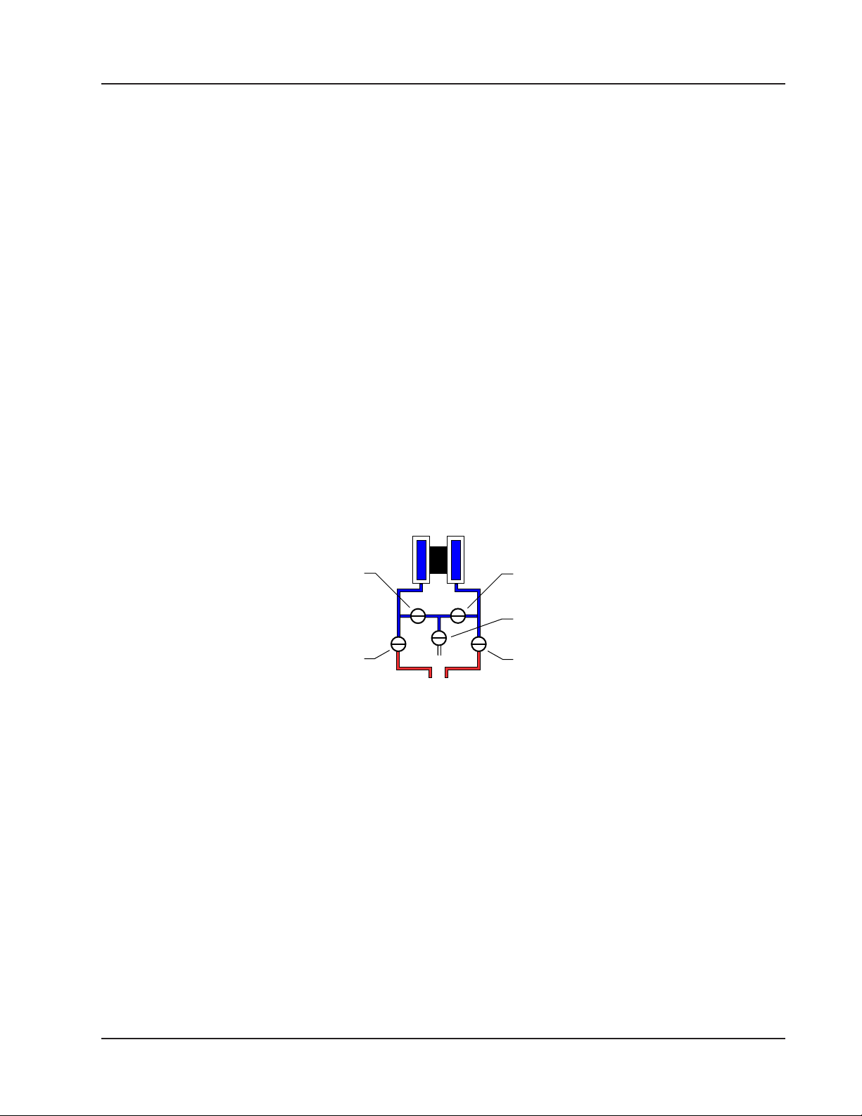
Scanner 3100 EFM Section 2
Performing a Manifold Leak Test
A manifold leak test is recommended prior to operating any differential pressure meter into service. Check the manifold
for leaks as follows:
1. Verify that the instrument is approximately level and is properly connected to the pressure source.
2. Make sure the vent valve in the manifold is closed. (The bypass/block valves should be open.)
3. Close both bypass/block valves on the manifold to isolate pressure between the block valve and the MVT (Figure
2.15).
4. Open both equalizer valves to distribute pressure throughout.
5. Monitor the pressure readout and watch for a steady decrease in pressure.
6. If desired, spray all connections and valves with soapy water and observe for bubbling to detect the location of any
leak(s). If leakage is indicated,
a. Depressurize the system by opening both bypass/block valves.
b. Check all manifold and piping joints.
c. Tighten connections and/or replace seals as necessary.
d. Repeat steps 3 through 6 to retest the manifold for leaks.
7. When the manifold is determined to be free of leaks, verify the condition of the equalizing valves as follows.
a. Close both equalizing valves and open the vent.
b. Monitor the differential pressure reading for any change.
8. Repair or replace the manifold as required if the differential pressure varies.
EQUALIZER
BYPASS/
BLOCK
Figure 2.15—Valve positions for manifold leak test
EQUALIZER
VENT
BYPASS/
BLOCK
Zero Offset (Static Pressure or Differential Pressure)
The static pressure input for the Scanner 3100 is zeroed at the factory before shipment. However, changes in temperature
and atmospheric pressure can cause the static pressure and differential pressure readings to vary. The inputs can be easily
zeroed in the eld prior to putting the Scanner 3100 into service, if necessary.
To zero the static pressure or differential pressure:
1. Close the bypass valves to isolate the pressure below the manifold (Figure 2.16, page 52).
2. Open the equalizer and vent valves.
3. Connect to the Scanner 3100 via the web interface.
4. Navigate to the Local I/O>DP:Diff Pres or Local I/O>SP:Stat Pres screen, click the Zero Offset tab, and click the
Modify button. You will be prompted to enter the Maintenance mode. See the Scanner 3100 Web Interface User
Manual for complete instructions.
5. Click the “Applied/As Left” eld, enter 0.0, and wait for the reading to be acquired.
6. Click Accept to exit the dialog. The measured zero offset will be displayed on the screen.
51
Page 52
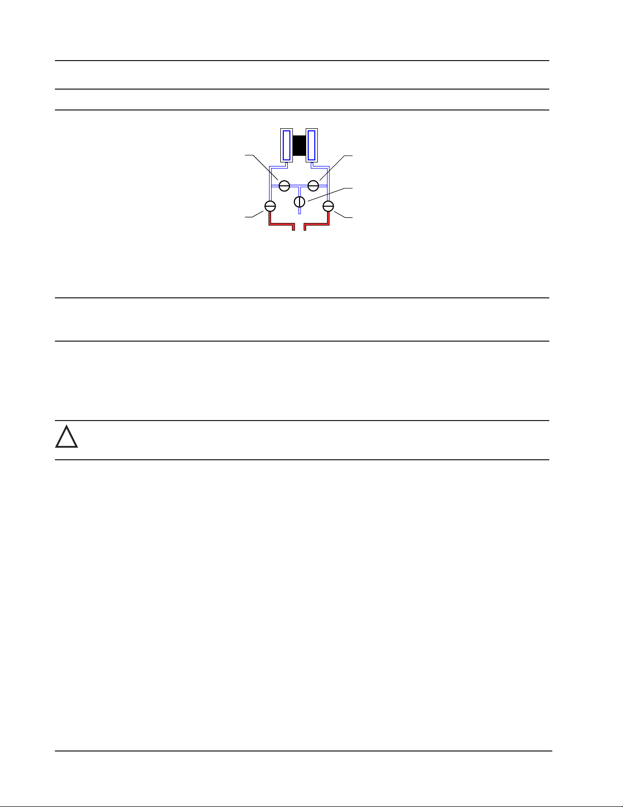
Section 2 Scanner 3100 EFM
7. Click Save to apply the offset to the Scanner 3100, and exit the Maintenance mode.
Note Zero offset values are cleared when a new calibration is saved.
EQUALIZER
BYPASS/
BLOCK
Figure 2.16—Valve positions for zero offset
EQUALIZER
VENT
BYPASS/
BLOCK
Static Pressure Calibration and Verication
Note The pressure range stamped on the MVT is expressed as psia (absolute). However, Scanner 3100 pressure
inputs are recalibrated as psig (gauge) at the factory before the device is shipped. Therefore, default pressure
readings displayed on the LCD and in the web interface are in terms of psig.
The static pressure and differential pressure inputs are calibrated and veried before the Scanner 3100 leaves the factory,
and recalibration in the eld may or may not be required. To comply with API standards for verication, “as found” readings should be recorded at approximately 0, 50, and 100 percent of the operating pressure range, increasing, and at 80, 20
and 0 percent of the operating pressure range, decreasing. For example, the static pressure measurements of a 1500-psi
sensor should be veried at 0 psi, 750 psi, and 1500 psi, then at 1200 psi, 300 psi, and 0 psi.
WARNING: Do not subject the Scanner 3100 to unnecessary shock or over-range pressure during mainte-
!
nance operations.
To calibrate the static pressure:
1. Close the bypass valves to isolate the pressure below the manifold (Figure 2.17, page 53).
2. Open the equalizer valves and vent valve to purge the lines.
3. Close the vent valve.
4. Connect a static pressure simulator to either side of the manifold.
5. Connect to the Scanner 3100 via the web interface.
6. Navigate to the Local I/O>SP:Stat Pres screen, click the Calibration tab, and click the Modify button. You will
be prompted to enter the Maintenance mode. See the Scanner 3100 Web Interface User Manual for complete
instructions.
7. Click the “Applied/As Left” eld, enter a known pressure.
8. Apply the same pressure to the MVT using the simulator and wait for the reading to be acquired.
9. Click Accept to accept the reading and exit the dialog. The pressure read by the simulator will be displayed in the
As Found eld and the calculated error between the pressure applied and the pressure read will appear beside it.
10. Repeat steps 7 through 9 to enter multiple calibration points.
11. When all calibration points have been entered, click Save to apply the new calibration settings.
12. Exit the Maintenance mode.
52
Page 53
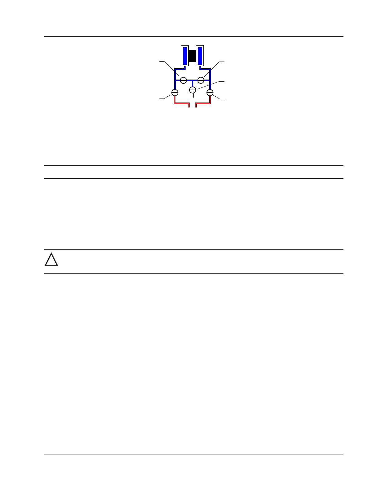
Scanner 3100 EFM Section 2
EQUALIZER
BYPASS/
BLOCK
Figure 2.17—Valve positions for static pressure calibration
EQUALIZER
VENT
BYPASS/
BLOCK
To verify the static pressure, perform the steps described in steps 6 through 12 above, except instead of clicking the Cali-
bration tab, click the Verication tab. You will be prompted to enter an applied value, and you will apply the same pres-
sure to the MVT, just as in the calibration process. The web interface will display a measured value and a percentage of
error. When you click Save, the measured values are written to memory.
Note Error is expressed as a percentage of the full scale of the MVT input range.
Differential Pressure Calibration and Verication
The static pressure and differential pressure inputs are calibrated and veried before the Scanner 3100 leaves the factory,
and recalibration in the eld may or may not be required. To comply with API standards for verication, “as found” readings should be recorded at approximately 0, 50, and 100 percent of the operating pressure range, increasing, and at 80,
20 and 0 percent of the operating pressure range, decreasing. For example, the differential pressure measurements of a
200 in H2O sensor should be veried at 0 in. H2O, 100 in. H2O, 200 in. H2O, then at 160 in. H2O, 40 in. H2O, and 0 in.
H2O.
WARNING: Do not subject the Scanner 3100 to unnecessary shock or over-range pressure during mainte-
!
nance operations.
To calibrate the differential pressure:
1. Close the bypass valves to isolate the pressure below the manifold (Figure 2.18, page 54).
2. Open the equalizer valves and vent valve to purge the lines.
3. Close the high-pressure side equalizer valve, leaving the low side vented.
4. Connect a pressure simulator to the high-pressure side of the manifold.
5. Connect to the Scanner 3100 with the web interface.
6. Navigate to the Local I/O>DP:Diff Pres screen, click the Calibration tab, and click the Modify button. You will
be prompted to enter the Maintenance mode. See the Scanner 3100 Web Interface User Manual for complete
instructions.
7. Click the “Applied/As Left” eld, enter a known pressure.
8. Apply the same amount of pressure to the high side of the MVT using the simulator. and wait for the reading to be
acquired.
9. Click Accept to accept the reading and exit the dialog. The pressure read by the simulator will be displayed in the
As Found eld and the calculated error between the pressure applied and the pressure read will appear beside it.
10. Repeat steps 7 through 9 to enter multiple calibration points.
11. When all calibration points have been entered, click Save to apply the new calibration settings.
12. Exit the Maintenance mode.
53
Page 54
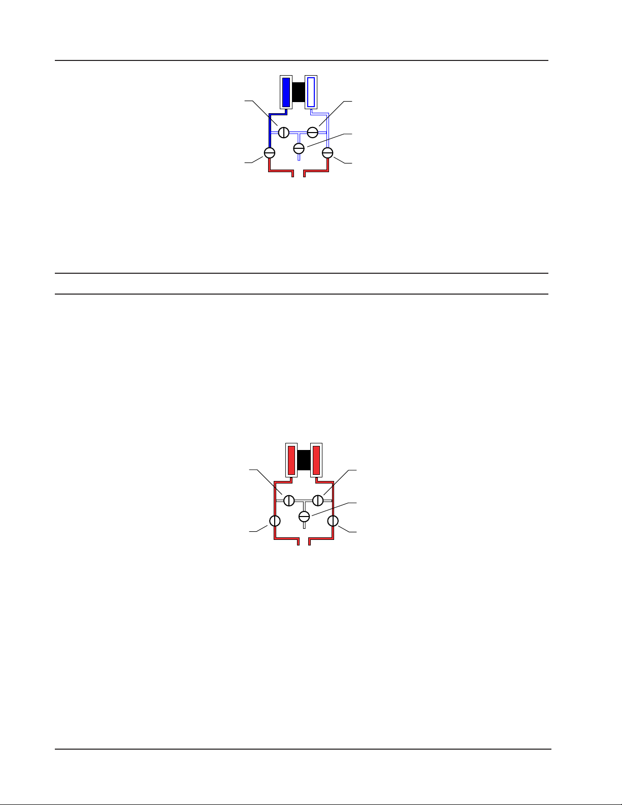
Section 2 Scanner 3100 EFM
EQUALIZER
BYPASS/
BLOCK
Figure 2.18—Valve positions for differential pressure calibration
EQUALIZER
VENT
BYPASS/
BLOCK
To verify the differential pressure, perform the steps described in steps 6 through 12 above, except instead of clicking the
Calibration tab, click the Verication tab. You will be prompted to enter an applied value, and you will apply the same
pressure to the MVT, just as in the calibration process. The web interface will display a measured value and a percentage
of error. When you click Save, the measured values are written to memory.
Note Error is expressed as a percentage of the full scale of the MVT input range.
Placing the Scanner into Operation
To put the Scanner into operation:
1. Close the vent valve (Figure 2.19).
2. Open the equalizer valves.
3. Open the bypass/block valves to allow pressure to be supplied to both sides of the MVT.
4. Close the equalizer valves.
5. Open the vent valve (optional, you may choose to leave the vent closed).
EQUALIZER
BYPASS/
BLOCK
Figure 2.19—Valve positions for placing the Scanner into operation
54
EQUALIZER
VENT
BYPASS/
BLOCK
Page 55
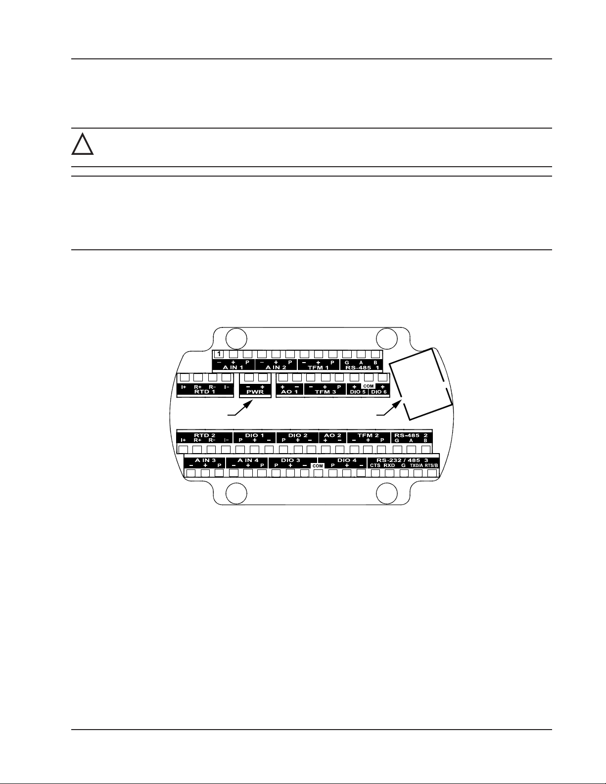
Scanner 3100 EFM Section 3
Section 3—Wiring the Scanner 3100 EFM
Field Wiring Connections
WARNING: Do not connect/disconnect equipment or change batteries unless the area is known to be non-
!
hazardous. The Scanner 3100 poses no hazard when opened in a safe area.
CAUTION All eld wiring must conform to the National Electrical Code, NFPA 70, Article 501-4(b) for installa-
tions within the United States or the Canadian Electric Code for installations within Canada. Local
wiring ordinances may also apply. All eld wiring must be rated for temperatures of 90 degC or
higher, and have a wire range of 22 to 14 AWG. Terminal block screws must be tightened to a minimum torque of 5 to 7 in-lb. (0.57 to 0.79 joules) to secure the wiring within the terminal block. Only
personnel who are experienced with eld wiring should perform these procedures.
To wire the Scanner 3100 for operation, complete the following eld connections:
1. Remove the rear cover of the enclosure to access the terminal board. All wiring connections can be made to this
board with the exception of the lithium batteries. Wire in accordance with the wiring diagrams shown on page 58
through page 65. See Figure 3.1 for help in locating the terminals by number.
2 3 4 5 6 7 8 9 10 11 12
13 14 15 16 17 18 19 20 21 22 23 24 25 26
Power Ethernet
27 28 29 30 31 32 33 34 35 36 37 38 39 40 41 42 43 44
45 46 47 48 49 50 51 52 53 54 55 56 57 58 59 60 61 62
Figure 3.1—Terminal board illustration with numbered terminals
2. Complete wiring of the terminal board as follows:
a. Connect wiring for external power to PWR (Terminals 17 and 18), if desired.
b. If the device is externally powered, route the protective earth grounding conductor into the enclosure with the
incoming power conductors and terminate it to the screw in the top of the enclosure (Figure 3.2, page 56).
Alternatively, connect an earth ground conductor to the external stainless steel ground lug of the enclosure and
to a ground rod or other suitable system earth ground, as shown in (Figure 3.2, page 56).
55
Page 56
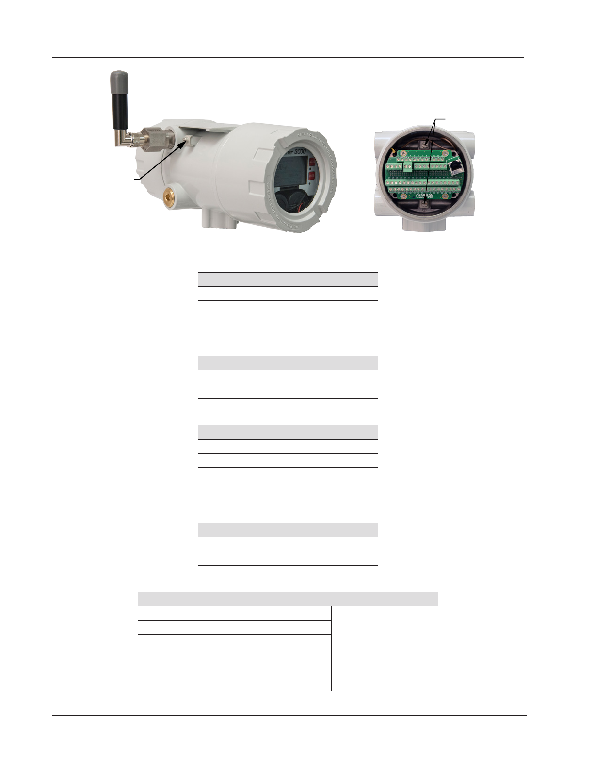
Ground screws
Section 3 Scanner 3100 EFM
Ground screw
Figure 3.2—External and internal ground screw locations
c. Connect the owmeter input wiring to TFM 1, TFM 2, or TFM 3, as required.
Terminal Block Termi nal s
TFM 1 7, 8, 9
TFM 2 39, 40, 41
TFM 3 21, 22, 23
d. Connect the process temperature input wiring to RTD 1 or RTD 2, as required.
Terminal Block Termi nal s
RTD 1 13, 14, 15, 16
RTD 2 27, 28, 29, 30
e. Connect analog input wiring to A IN 1, A IN 2, A IN 3 or A IN 4, as required.
Terminal Block Termi nal s
A IN 1 1, 2 , 3
A IN 2 4, 5, 6
A IN 3 45, 46, 47
A IN 4 48, 49, 50
f. Connect analog output wiring to AO 1 or AO 2, as required.
Terminal Block Termi nal s
AO 1 19, 20
AO 2 37, 38
g. Connect digital input/output wiring to DIO 1, DIO 2, DIO 3 or DIO 4, as required.
Terminal Block Te rmin als
DIO 1 31, 32, 33, 54 (COM) Use 54 (COM) only with
DIOs 1, 2, 3 and 4.
DIOs 5 and 6.
DIO 2 34, 35, 36, 54 (COM)
DIO 3 51, 52, 53, 54 (COM)
DIO 4 54 (COM), 55, 56, 57
DIO 5 24, 25 (COM) Use 25 (COM) only with
DIO 6 25 (COM), 26
56
Page 57
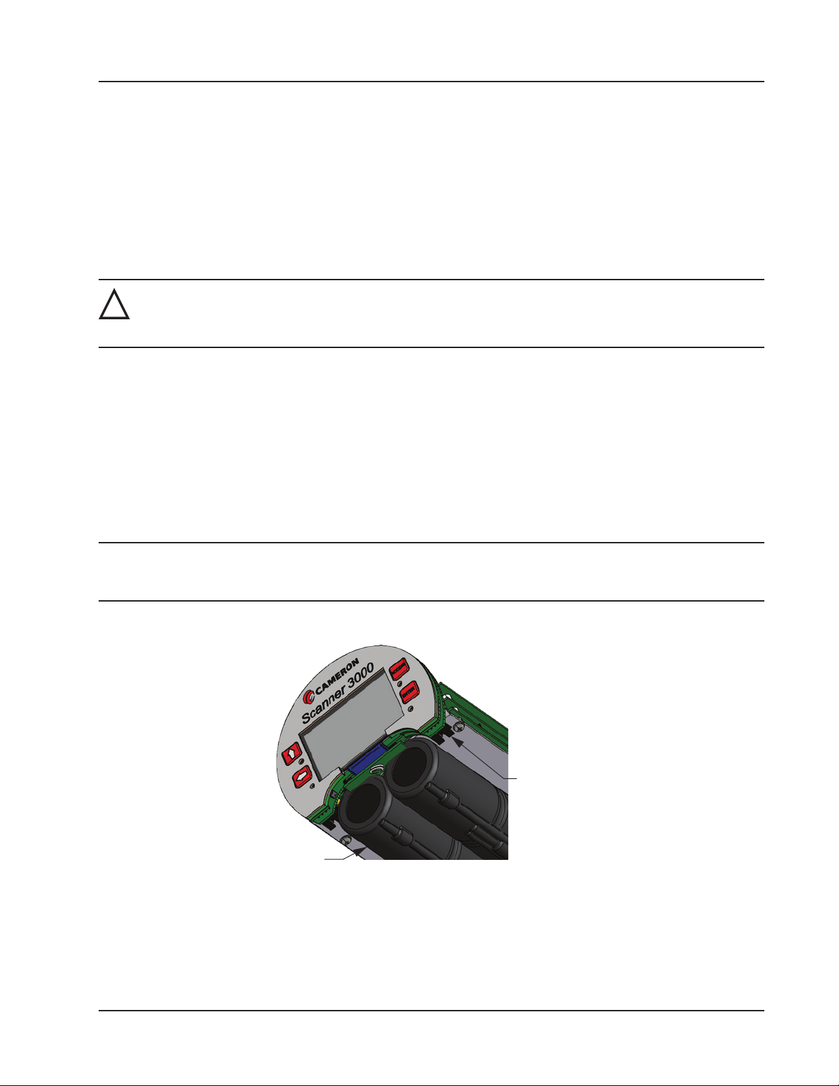
connector (2)
pack (2)
Scanner 3100 EFM Section 3
3. Congure and calibrate the Scanner 3100.
3. Replace the enclosure cover.
Power Supply Wiring
Internal Power Supply
Cameron’s 7.2 V lithium battery packs provide reliable backup power when used with an external primary power supply.
The Scanner 3100 supports up to two battery packs simultaneously. The battery compartment is located below the display/keypad assembly and is readily accessible when the front cover is removed from the enclosure.
WARNING: EXPLOSION RISK. Housing temperature must not exceed 70 degC (158 degF). Excessive tem-
!
peratures, which could result from ambient conditions combined with radiated and conductive heat from
the process, could cause the internal lithium battery to ignite or explode.
To determine which battery pack to change, look at the battery life indicator on the device display. See Status Indicators
(Glyphs), page 79 and Table 5.1—Device Status Glyph Denitions, page 80 for additional information.
To install a battery pack,
1. Insert the pack so that the cable end of the battery faces the back of the compartment.
2. Wrap the loose end of the cable toward the front of the compartment so that the connector is visible with the pack
installed.
3. Locate the two receptacles on the back of the display board assembly (Figure 3.3).
4. Taking note of pin positions on the cable receptacle, slide the battery cable connector securely onto the pins of the
receptacle nearest the battery pack.
Note Proceed carefully when connecting the battery packs to the plastic receptacles to avoid damaging the connector
or bending pins. Using a pair of needle-nose pliers to grasp the plastic battery cable connector may aid in aligning the connector and receptacle pins when connecting and disconnecting battery packs.
5. Repeat steps 1 through 4 to install the second battery pack.
Battery pack
Battery
Figure 3.3—Lithium battery pack connectors (shown with enclosure removed from view)
Battery Life
Although external power is recommended for continuous use, the dual battery packs will autonomously power the Scanner 3100 for an estimated 2 to 3 weeks under a base load (no analog inputs, digital outputs, or Ethernet communication).
57
Page 58
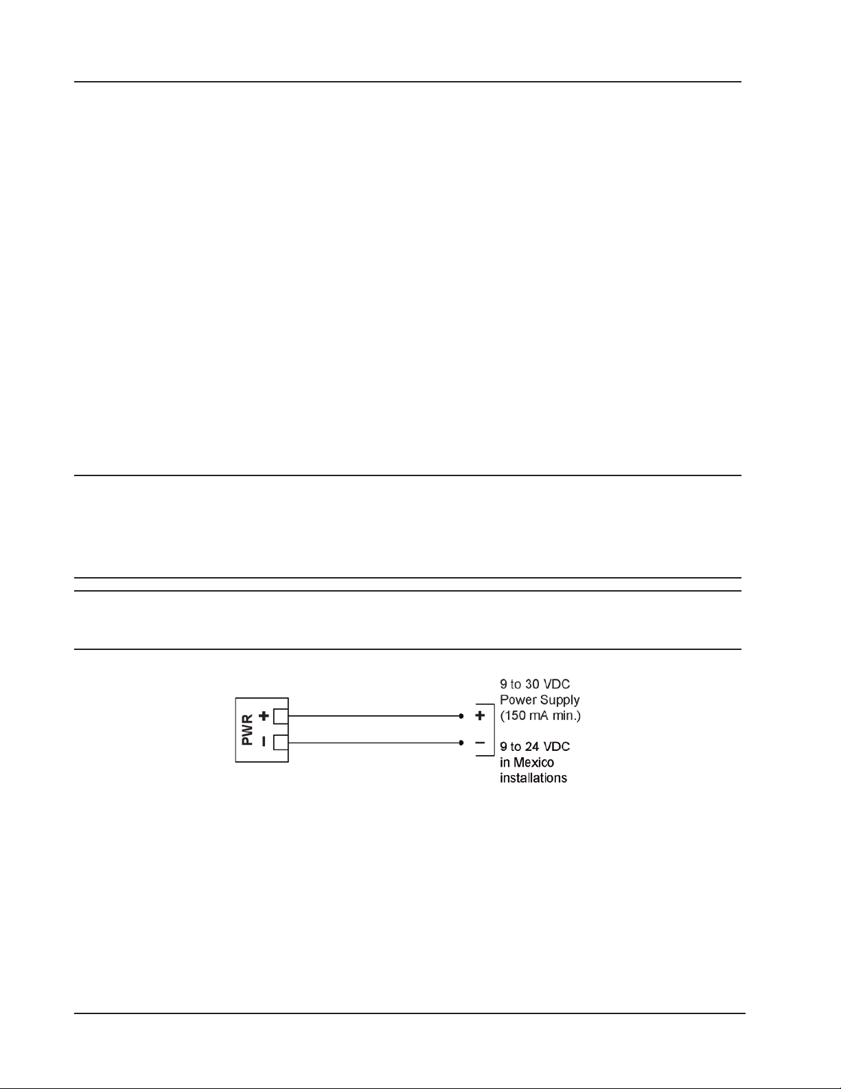
Section 3 Scanner 3100 EFM
Should the primary power supply fail, take the following precautions to maximize battery life:
• Ensure calculation frequency is no greater than once per minute.
• Ensure logging frequency (interval) is no greater than once per hour.
• Ensure download frequency is no greater than once per month.
• Avoid operating at extremely cold temperatures.
• Avoid the use of digital outputs (pulse or alarm).
• Avoid the use of analog inputs.
• Avoid the use of the Ethernet port (web interface access).
• Avoid powering an external transmitter with the Scanner 3100.
External Power Supply
The Scanner 3100 can be connected to a remote DC power supply (Figure 3.4). The power supply and cable must be capable of supplying 9 to 30 VDC at 150 mA minimum (9 to 24 VDC at 150 mA for installations in Mexico).
The external power supply used with CSA-approved units must be an approved SELV source, insulated from the AC
main by double/reinforced insulation per CSA C22.2, No. 61010-1-04/UL 61010-1, 2nd Edition.
ATEX-approved devices should be powered with an external SELV power supply (Um = 30 VDC) and an internal 7.8 V
battery pack as backup, per ATEX Certicate Number Sira 15ATEX 1122X.
Caution All eld wiring must conform to the National Electrical Code, NFPA 70, Article 501-4(b) for installa-
tions within the United States or as specied in Section 18-156 of the Canadian Electrical Code for
installations within Canada. Local wiring ordinances may also apply. All eld wiring must have a
wire range of 22 to 14 AWG and terminal block screws must be tightened to a minimum torque of 5
to 7 in-lb. to secure the wiring within the terminal block. Only personnel who are experienced with
eld wiring should perform these procedures.
Important In all applications using an external power supply, a switch or circuit breaker must be included in
the safe area within easy reach of the operator. The switch or circuit breaker must be marked as
the “disconnect” for the safe area external DC power supply.
Figure 3.4—External power supply
58
Page 59

Turbine Magnetic
TFM 1, 2, 3
2-Wire
RED
Scanner 3100 EFM Section 3
Input Wiring
Turbine Flowmeter Inputs
TFM inputs 1, 2 and 3 on the terminal board provide the turbine owmeter input signal generated by a magnetic pickup,
enabling the Scanner 3100 to calculate and display instantaneous ow rates and accumulated totals. Wire as shown in
Figure 3.5.
RED
BLACK
A
B
Pickup Input
Figure 3.5—Flowmeter input
RTD Inputs
The 4-wire RTDs described in Appendix A of this manual are recommended for measuring temperature in temperaturecompensated gas and liquid calculations, though a 2- or 3-wire RTD may prove functional. Wiring is essentially the same
for all three models, though wire color may vary as indicated. Wire as shown in Figure 3.6.
WHITE
I-
RTD-
RTD+
I+
I-
RTD-
RED
WHITE
WHITE
R- I-
R+
RTD 1, 2
I+
3-Wire
R- I-
JUMPER
JUMPER
Figure 3.6—Process temperature input
R+
RTD 1, 2
I+
4-Wire
R- I-
R+
RTD 1, 2
I+
JUMPER
RTD+
I+
RTD-
RTD+
I+
RED
WHITE
I-
WHITE
RED
59
Page 60
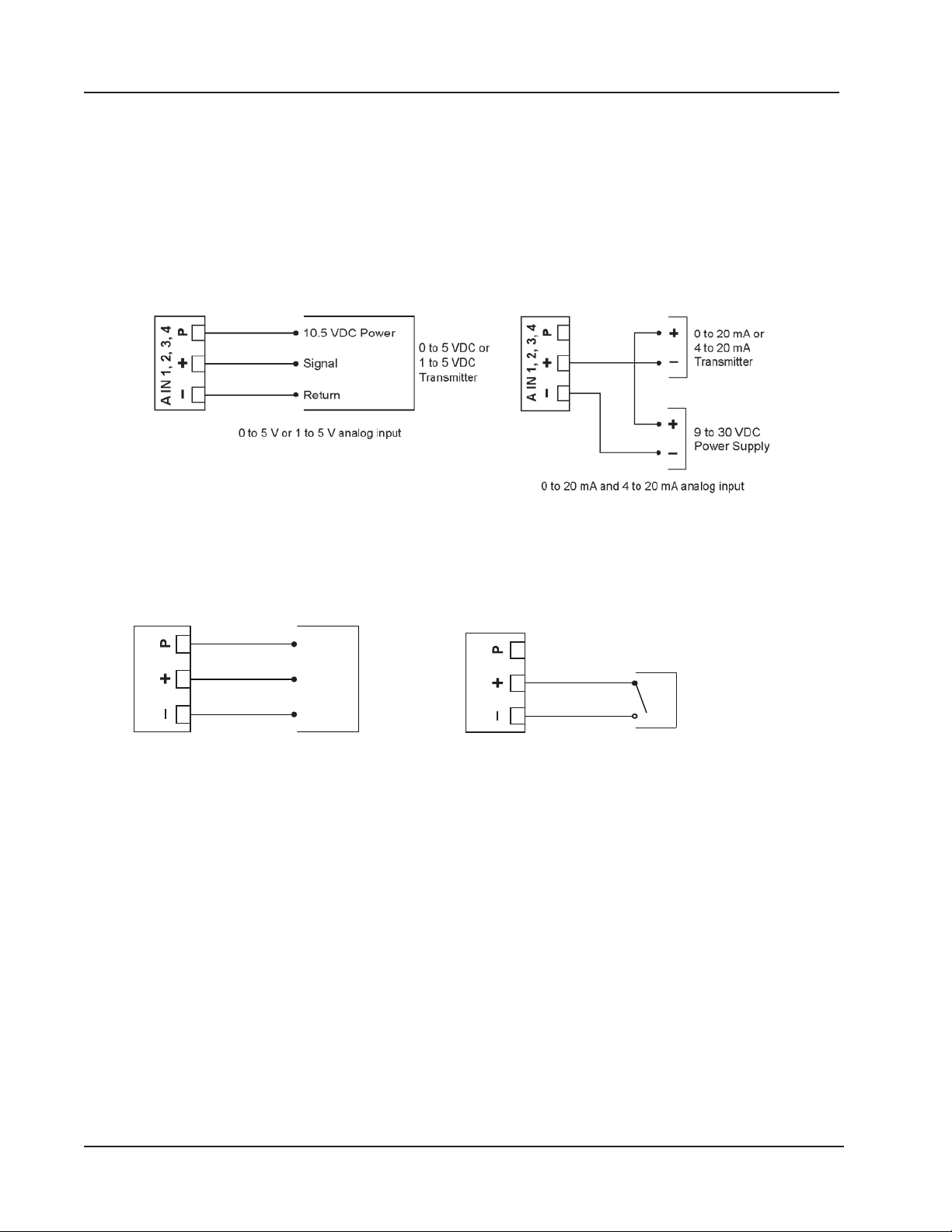
Pre-Amp
TFM 1, 2, 3
TFM 1, 2, 3
Contact Closure
Input
Section 3 Scanner 3100 EFM
Analog Inputs
The analog inputs (Figure 3.7), which can be congured for a 0 to 5 V, 1 to 5 V, 0 to 20 mA or 4 to 20 mA signal, can
be used to receive readings from a pressure or temperature transmitter for use in any ow run. Alternatively, they can be
used to log measurements from any device with a 0 to 5 V, 1 to 5 V, 0 to 20 mA or 4 to 20 mA output. An on-board resistor is automatically enabled when a current input is congured in the Scanner 3100 web interface. Therefore, no external
resistor is required for use with a current input.
The Scanner 3100 provides approximately 10 VDC at 20 mA for powering a 0 to 5 V or 1 to 5 V transmitter. It is not
suitable for powering a 4 to 20 mA transmitter. For reduced power consumption, disable analog inputs in the Scanner
3100 web interface when they are not in use.
Figure 3.7—Analog input
Pulse Inputs
Pulse inputs (Figure 3.8) provide an input for high-amplitude pulse (frequency) signals, such as signals from a turbine
meter equipped with a preamplier (shown at left) or signals from a positive displacement meter (shown at right).
Power
Out
GND
Figure 3.8—Pulse input
Input
60
Page 61
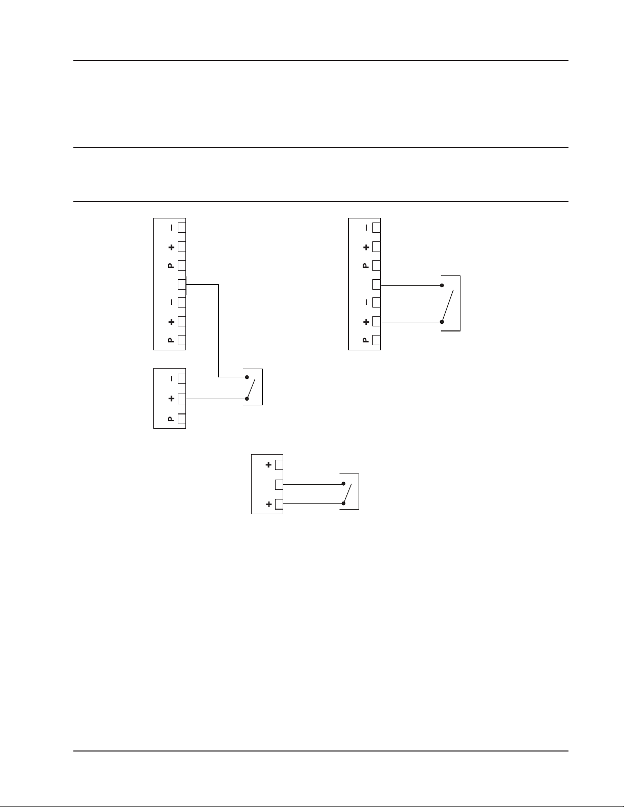
Contact
DIO 1, 2
DIO 5, 6
Signal (+)
Contact
Scanner 3100 EFM Section 3
Digital Inputs—Contact Closure
The digital contact closure input (Figure 3.9, top) provides an input for use with any relay contact switch. DIO 1 through
DIO 4 are optically isolated. DIO 5 and DIO 6 (Figure 3.9, bottom) are non-isolated. To congure a contact closure using
the Scanner 3100 web interface, choose Contact Closure as the input type and select a trigger state to indicate whether
the pulse will trigger when the signal is high or when it is low.
Note Digital input/output common (COM) connections are not interchangeable. The COM connection located between
DIO 3 and DIO 4 terminals cannot be used with DIO 5 and DIO 6 wiring and vice versa. The COM connections
between DIO 3 and DIO 4 terminals contains a 3.6 kΩ resistor to circuit ground. The COM connection between
DIO 3 and DIO 4 terminals can be used with DIOs 1 through 4.
COM (-)
COM
DIO 3 DIO 4
Signal (+)
Figure 3.9—Digital contact closure
COM (-)
COM
Signal (+)
DIO 3 DIO 4
Relay
Contact
Optically-isolated digital input
COM (-)
COM
Non-isolated digital input for use with internal pull-up resistor
Relay
Relay
61
Page 62
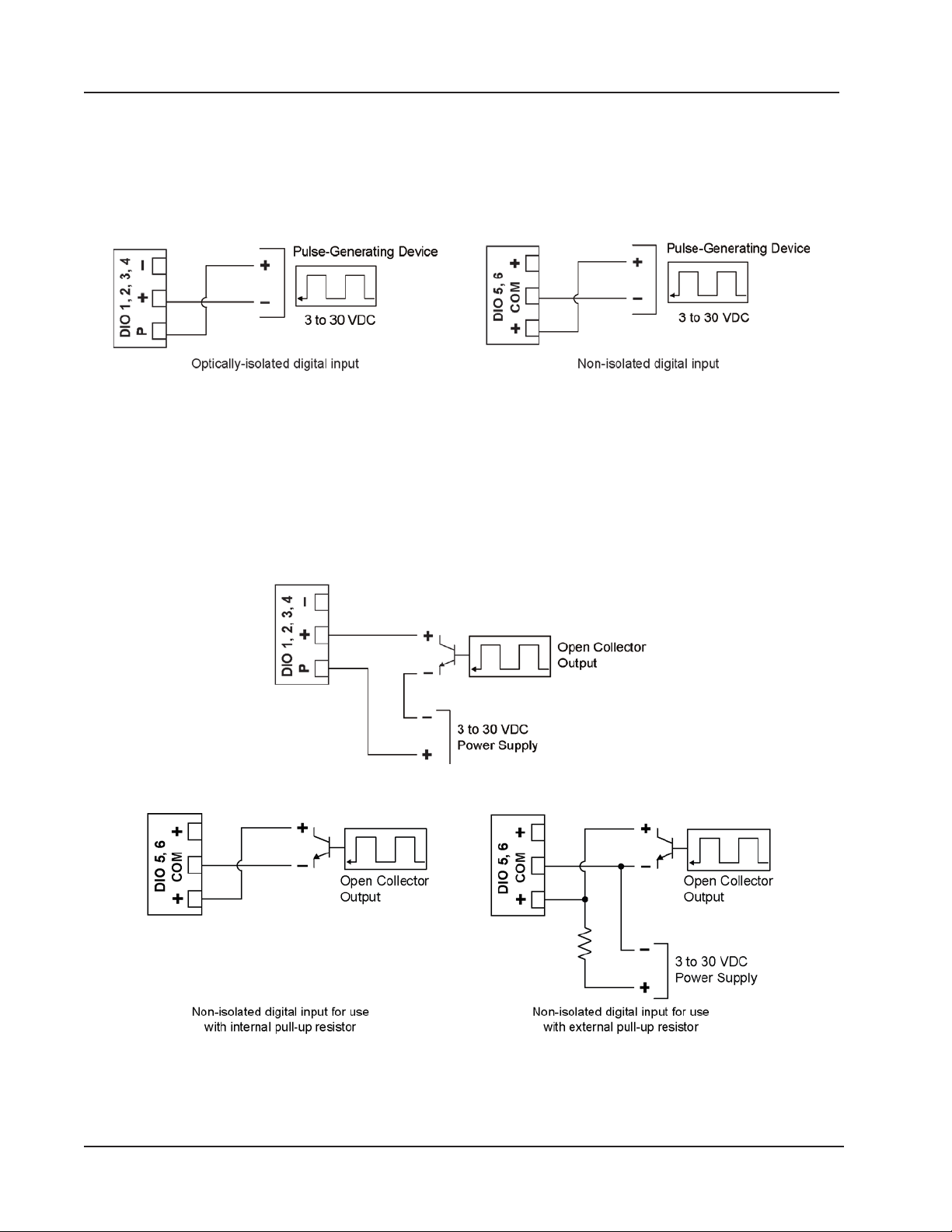
Section 3 Scanner 3100 EFM
Digital Inputs—Pulse
The digital pulse input (Figure 3.10) provides an input for use with any 3 to 30 VDC pulse-generating device. DIOs 1
through 4 (shown at left) are optically isolated. DIOs 5 and 6 (shown at right) are non-isolated.
To congure a pulse input using the web interface, choose Pulse as the input type, and select a trigger state to indicate
whether the pulse will trigger when the signal is high or when it is low.
Figure 3.10—Digital pulse input
Digital Inputs—Open Collector
The digital open collector input (Figure 3.11) provides an input for use with any device with an open collector output.
DIOs 1 through 4 (top) are optically isolated. DIOs 5 and 6 (bottom) are non-isolated and can be wired for use with an
internal pull-up resistor, or with a customer-supplied resistor. When the internal pull-up resistor is used, signals can be
transmitted over short distances without the use of an external power supply.
To congure an open collector input using the web interface, choose Open Collector as the input type, and select a trigger state to indicate whether the input is to trigger when the signal is high or when it is low.
Optically-isolated digital input
Figure 3.11—Digital open collector input
62
Page 63
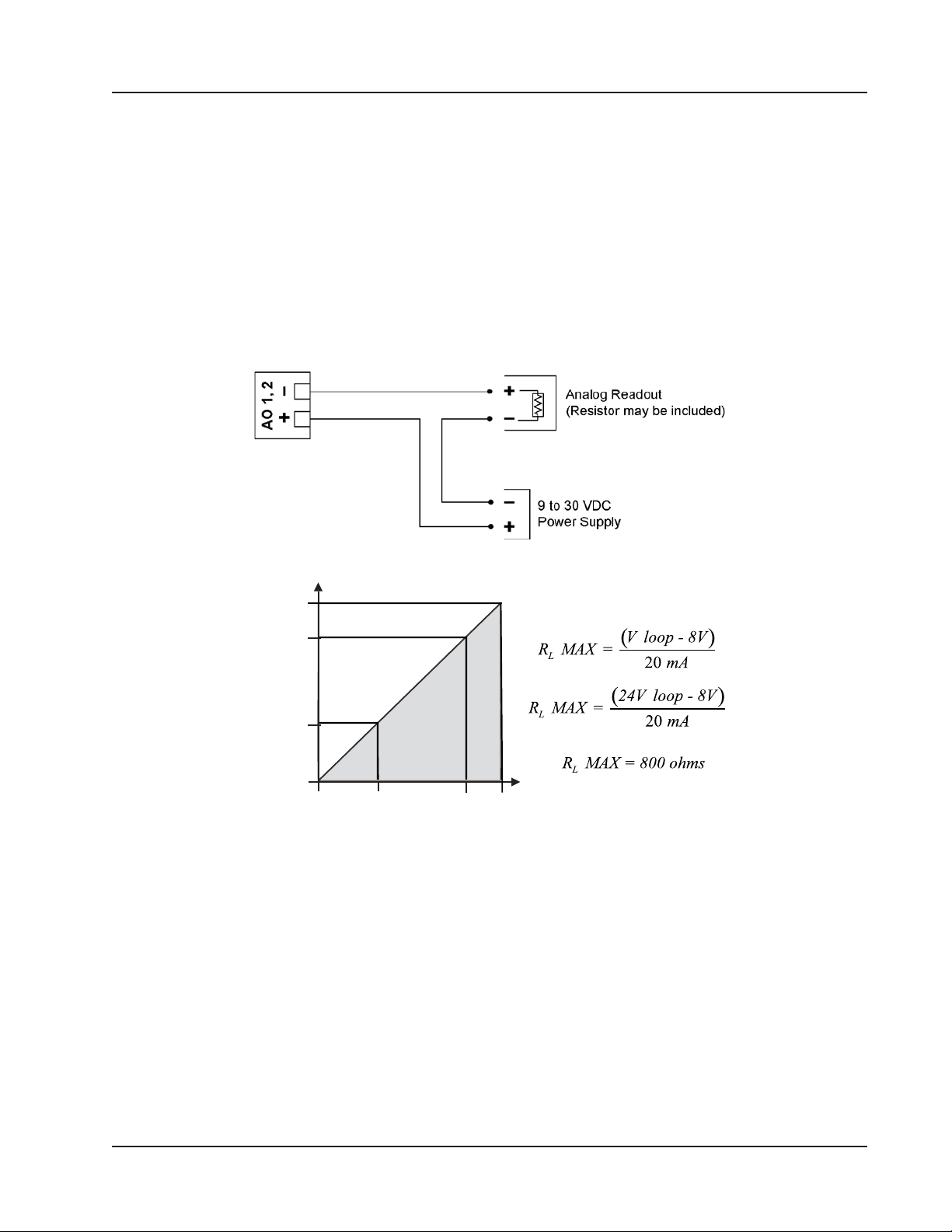
LOOP SU PPLY VOLTAGE (VDC)
LOAD RESISTANCE (OHM S)
Scanner 3100 EFM Section 3
Output Wiring
Analog (4 to 20 mA) Outputs
The 4 to 20 mA output (Figure 3.12) provides a linear current output that can be congured to represent any parameter
in the holding registers using the Scanner 3100 web interface. This output requires a two-conductor cable connected to
a 9 to 30 VDC power supply (voltage required is dependent on loop resistance) and a current readout device located in
the remote location. The analog outputs are electrically isolated from each other and from the main electronics. See the
Scanner 3100 Web Interface User Manual for information on conguring and calibrating zero and full-scale values.
The load resistance vs. loop supply voltage graph below shows the minimum voltage required to power the instrument
for a given loop resistance. In addition, the mathematical relationship between loop voltage and load resistance is given.
For example, if a power supply voltage of 24 volts is available to power the current loop, the maximum load resistance
would be 800 ohms.
1100
800
200
0
8 12 24 30
Figure 3.12—Analog (4 to 20 mA) output
OPERATING
REGION
63
Page 64
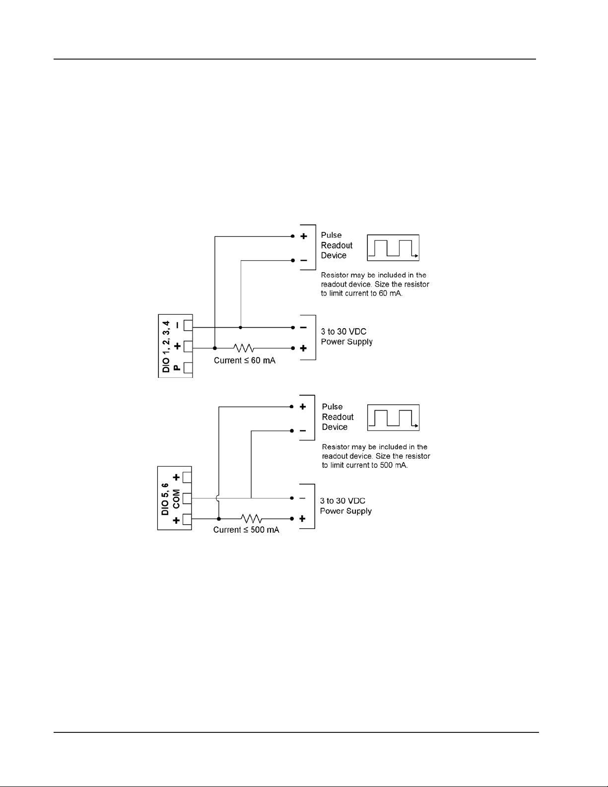
Section 3 Scanner 3100 EFM
Digital Outputs
The standard Scanner 3100 supports six solid-state digital outputs that are congurable as pulse outputs, alarm outputs,
conditional outputs, or programmed outputs using time of day or an output state as the trigger.
DIO 1 through DIO 4 are isolated and rated for a maximum of 60 mA at 30 VDC. Maximum frequency is 50 Hz. Wire as
shown in Figure 3.13, page 64 (top diagram). Because the circuit is isolated, it can be used with any other feature on
the Scanner 3100. A two-conductor cable from the Scanner 3100 to the remote location is required.
DIO 5 and DIO 6 are designed for handling signicantly higher currents and can be used to control power to another device. Wire as shown in Figure 3.13, page 64 (bottom diagram). These terminals are rated for a maximum of 500 mA at
30 VDC. Maximum frequency is 50 Hz.
For reduced power consumption, disable digital outputs using the Scanner 3100 web interface when they are not in use.
Figure 3.13—Pulse output wiring
Optically-isolated digital output
Non-isolated digital output
64
Page 65
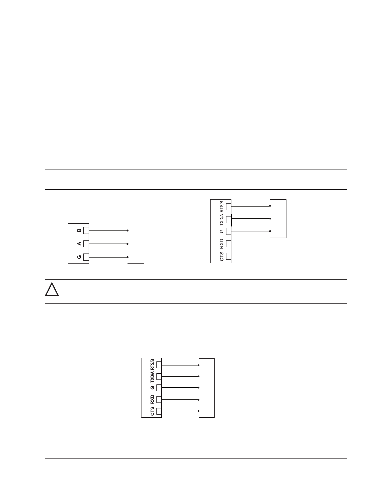
RS-485 1, 2
COM
A
B
RS-485 Device
COM
RS-232/485 3
RS-485 Device
A
B
RS-232/485 3
RS-232 Device
Scanner 3100 EFM Section 3
Communications
RS-485 Communications
The Scanner 3100 supports digital serial communications using EIA-RS-485 hardware with Modicon Modbus protocol.
RS-485 communications are supported by three ports with a baud range of 300 to 115.2K. Ports 1, 2, and 3 can be used
simultaneously, if desired, and all three ports are protected from high-voltage transients. The circuit can be terminated by
enabling an internal termination resistor in the web interface. See the Scanner 3100 Web Interface User Manual for details. Wire as shown in Figure 3.14, page 65.
Ports 1 and 2 (shown at left) are designed for use with low-power peripherals such as radios, gas chromatographs, other
wired Modbus devices, and wired Scanner slave devices, and are always enabled. If a large number of slave devices are
to be connected to a Scanner 3100 network via a serial port, more than one communication port may be required, depending on archive periods and baud rates desired.
Port 3 (shown at right) supports both RS-485 and RS-232 communications and may be preferred for continuous, highspeed communications. Port 3 is disabled by default, and must be enabled before use. The mode (RS-485 or RS-232) is
automatically detected by the hardware.
Note Not all RS-485 devices, including converters, identify A and B terms consistently. If communications are not
established, switch the wires.
Figure 3.14—RS-485 communications
WARNING: To prevent ignition of hazardous atmospheres, do not remove the Scanner 3100 cover while
!
circuits are alive. The Scanner 3100 poses no hazard when opened in a safe area.
RS-232 Communications
RS-232 communications are supported by Port 3, a high-power port that also supports RS-485 communications. RS-232
communications are useful for short-range communications (typically 50 ft or less) with radios and some Modbus peripheral devices. Wire as shown in Figure 3.15. Port 3 must be enabled and congured for RS-485 or RS-232 communications via the web interface.
CTS
RXD
COM
TXD
RTS
Figure 3.15—RS-232 communications
65
Page 66

Section 3 Scanner 3100 EFM
Ethernet Communications
An RJ-45 connector (Figure 3.1, page 55) provides the Ethernet communications required for accessing the web interface via a web browser and for transmitting data over two TCP ports. The TCP ports support Modbus TCP and Modbusover-TCP protocols and can be congured individually (assigned to unique port numbers) using the web interface.
Section 4 describes two methods for using the Ethernet port to connect the Scanner 3100 to a PC or laptop.
66
Page 67

Scanner 3100 EFM Section 4
Section 4—Connecting to the Scanner 3100 Interface
To connect to the Scanner 3100 interface, you will need to establish a local area network between your computer (PC or
laptop) and the Scanner using Ethernet cables and possibly, a router. An IP address will be assigned to the Scanner 3100
during this process. You can then enter the IP address into the address bar of any web browser to login to the Scanner
3100 interface.
You can access the Scanner 3100 web interface from any laptop, tablet, or smart phone equipped with a web browser.
This section describes IP address options and three methods for establishing a local area network with the Scanner 3100
EFM.
Important The Scanner 3100 web interface requires JavaScript to be enabled. For instructions about enabling
JavaScript in the 5 most commonly used web browsers, see http://www.enable-javascript.com/.
Important Before attempting to connect to the Scanner 3100, check with your Information Technology (IT)
department to determine the best method of connection, review relevant company policies, and
obtain permission before attempting to add the device to a corporate network infrastructure.
IP Address Options
The Scanner 3100 accommodates both dynamic and static IP addresses.
Dynamic IP is considered the least restrictive means of supporting communications with the Scanner, and is often preferred by corporations with extensive IP needs. However, you should be aware that dynamic IP addresses are subject to
change over time (the frequency of such changes is controlled by corporate network settings). If the Scanner 3100 device
is to be installed in a remote location, a dynamic IP address may not be the most reliable choice.
Static IP addresses are unchanging, which helps protect user access to the device but restricts the address from being
used with any other device. A static IP address may be a consideration if you must access the device from a great distance and do not have a local contact near the device who can verify the IP address from the device display.
Note Static IP addresses can be disabled during rmware upgrades, requiring onsite assistance to restore the static IP
address.
Dynamic IP is recommended for initial setup of the device. Once communication with the device is achieved, a static IP
address can be assigned, if applicable. Basic instructions for changing an IP address are provided in the Scanner 3100
Web Interface User Manual linked to the web interface. step-by-step instructions may vary with web utilities and computer operating systems. If you are unfamiliar with this process, seek assistance from an IT professional.
Important The following instructions will help guide you through an initial connection to the Scanner 3100
using the Scanner’s dynamic IP address. If a static IP address is required for ongoing Scanner
communications, the IP can be recongured in the web interface after this initial connection. See
the static IP conguration instructions in the Scanner 3100 Web Interface User Manual for details.
67
Page 68
Section 4 Scanner 3100 EFM
Connection Options
A computer can be connected to a Scanner 3100 using either of two methods:
• Direct (1 to 1) Connection (Ethernet Only). This method is recommended only if you have experience changing
Windows settings and have the administrative rights to assign a static IP address to your computer.
• Standard Connection (Ethernet and WiFi). This method requires no changes to computer settings and is typically
the easiest connection method for novice users. Three different types of connections are supported by the Scanner
3100:
– Add the Scanner 3100 to an existing corporate network (contact your IT professional for assistance)
– Create an ad hoc network using a wireless router (for locations without an external power supply, Cameron
recommends the use of a portable router)
– Create a permanent local network using a Cameron WiFi communications accessory equipped with a wireless
modem
Direct (1-to-1) Connection to a Laptop
To establish a direct connection between the Scanner 3100 and a laptop, perform the steps below.
1. Obtain the following hardware:
– External power supply
– Ethernet cable (cross-over or straight CAT 5 or greater)
2. Remove the Scanner 3100 rear enclosure cover and connect the power supply to the power terminal (see External
Power Supply, page 58 for detailed instructions). Allow approximately one minute for the Scanner 3100 to boot.
WARNING: To prevent ignition of hazardous atmospheres, do not remove the cover while circuits are
!
alive. The Scanner 3100 poses no hazard when opened in a safe area.
3. If the Scanner 3100 has the factory default dynamic IP address, navigate to the laptop’s Control Panel settings and
change the IP address of the laptop to 192.168.0.XXX where “XXX” is any number sequence other than “040.” If
the IP address of the Scanner 3100 has been changed to a static IP address, change the IP address of the laptop to
match the current static IP address, changing the last three digits as required. Ensure that the laptop uses the same
subnet and differs only in the last three digits.
4. Connect the Ethernet cable to the RJ-45 connector on the Scanner 3100 terminal board and to the laptop Ethernet
port.
5. Open a web browser on the laptop and enter the IP address shown at the top of the Scanner display. Press “Enter”
and wait for the Device Login screen to load.
6. On the Device Login screen, enter the appropriate user name and password. Default entries (case-sensitive) are:
User Name: admin
Password: scanner
7. Press the “Login” button on the screen.
Important Changing the administrative password after the initial login is strongly recommended. See the
“Security” section of the Scanner 3100 Web Interface User Manual for instructions on changing the
administrative password and setting up additional users with password-protected access.
68
Page 69

Scanner 3100 EFM Section 4
Ad-Hoc Wireless Router Connection
If you have no wireless access point or work for a company that does not wish to add another device to the corporate
Ethernet network, a portable wireless router can be used to establish a local area network. Routers with a single LAN
port must be used with a wireless-enabled laptop. Multi-port wireless routers can be used to establish a wireless connection using any standard laptop with or without wireless capabilities.
Important Cameron supports only select third-party portable wireless routers that are compatible with the
Windows 7 operating system and are IEEE 802.11 compliant. Contact your local Cameron representative for a list of supported routers.
To establish the Scanner 3100’s connection to a laptop via a wireless router, obtain the following hardware:
• External power supply (for USB-powered routers, a USB cable connected to a computer provides this supply)
• Router with one or more LAN ports
• One or two Ethernet cables (cross-over or straight CAT 5 or greater)
– One cable for routers with a single LAN port (for use with a wireless communications-enabled laptop)
– Two cables for routers with multiple LAN ports
If the selected router has only one LAN port (as with many portable routers), wireless communications must be used
to connect to the laptop. In this instance, the laptop must have wireless capabilities to match router specications. See
Single-Port Router Option (Requires Wireless-Enabled Laptop), for setup instructions.
If the selected router has multiple LAN ports, see Multi-Port Router Option, page 70 for setup instructions.
Single-Port Router Option (Requires Wireless-Enabled Laptop)
1. Identify the router’s IP address, user name, and password in the router manufacturer literature.
2. Enable wireless communications on the laptop.
3. Boot the router using the following procedure:
a. Connect power to the router with the supplied power source. If using a USB-powered router, connect the USB
power cable to the laptop and to the router to power the router from the laptop. If using a battery-powered
router, turn on the router.
b. Wait approximately 20 seconds.
c. Connect an Ethernet cable to the laptop and to the router LAN/WAN port.
4. Obtain wireless network information using the following procedure:
a. Open the laptop browser, enter the router’s IP address, and press “Enter.”
b. At the login prompt, enter the router’s user name and password and click OK to display the router home page.
c. Record the SSID, security type, encryption type, and pre-shared security key for your wireless network. This
information is found in router’s manufacturer instructions and is required to complete step 5.
d. Close the web browser and disconnect the Ethernet cable from the router and the laptop.
5. Congure the wireless network as follows:
a. Enable wireless communications on the laptop.
b. From the laptop’s Control Panel, access the Wireless Network Conguration utility.
c. Choose Add in the Wireless Network Management Tool.
d. Select Manually create a network prole.
e. Enter the wireless network information recorded in step 4c.
69
Page 70

Section 4 Scanner 3100 EFM
f. Select Start this connection automatically and click Next.
6. Click the “Wireless Communication” icon on the Quick Access tray at the bottom of the laptop screen. If you cannot
see the icon, expand the Quick Access tray.
7. From the list of wireless networks connected, select the wireless network you created and click Connect.
8. Proceed to Scanner 3100 Network Connection below.
Multi-Port Router Option
If the router in use has multiple LAN ports, proceed as follows:
1. Boot the router by performing the following tasks.
a. Connect power to the router using the supplied power source. If using a USB-powered router, connect the USB
power cable to the laptop and to the router to power the router from the laptop.
b. Wait approximately 20 seconds.
c. Connect an Ethernet cable to the laptop and to one of the router LAN ports.
2. Proceed to Scanner 3100 Network Connection below.
Scanner 3100 Network Connection
To connect the Scanner 3100 to the local area network (LAN), use the following procedures.
1. Remove the Scanner 3100 rear enclosure cover and connect the power supply to the power terminal. The Scanner
3100 will take approximately one minute to boot.
2. Connect an Ethernet cable to the terminal board’s RJ-45 connector and to the router’s LAN port. The Scanner 3100
will detect the network automatically.
3. Record the Scanner 3100’s IP address displayed in the upper left corner of the LCD display.
4. Open a web browser, type the Scanner 3100’s IP address in the address bar, and press “Enter” on the keyboard or
keypad of your device.
5. On the Device Login screen, enter the appropriate user name and password. Default entries (case-sensitive) are:
User Name: admin
Password: scanner
6. Press the “Login” button on the screen.
Note If the loading stalls, click Refresh. If a connection to the Scanner is not established, verify the IP address and
repeat step 4.
Important Changing the administrative password after the initial login is strongly recommended. See the
“Security” section of the Scanner 3100 Web Interface User Manual for instructions on changing the
administrative password, and setting up additional users with password-protected access.
WiFi Communications Accessory
The WiFi communications accessory (“WiFi box”) provides wireless access to the Scanner 3100 via the web interface
and a permanently installed wireless modem. The WiFi box is externally powered and can be accessed by multiple users.
It also allows users to communicate to the Scanner 3100 from a safe distance outside a Class I, Div. 1 area for compliance with hazardous area safety regulations.
The WiFi solution includes a wireless modem, modem power supply, and internal antenna cable/lightning arrestor assembled inside a weatherproof Class I, Div. 2 enclosure and an external remote-mount antenna with pole-mounting
hardware. A 10-ft antenna cable and an Ethernet/power bundled cable (5, 10, 20 or 30 feet) are optionally available for
70
Page 71
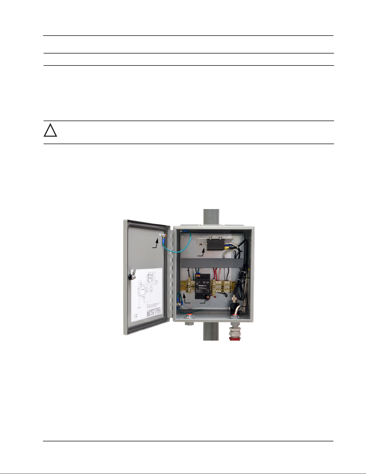
Modem
Fuse
Interior
ground
Scanner 3100 EFM Section 4
purchase.
Note A user-supplied external 110/240 VAC, 50/60 Hz power supply is required to power the WiFi box.
The WiFi box is pre-assembled and the router is pre-congured at the factory. Field wiring is limited to power connections to the box and to the Scanner 3100 and an Ethernet connection to the Scanner 3100.
Installation
The WiFi box is approved for mounting in Class 1, Div. 2, Group A, B, C, or D locations. Select a suitable location in a
safe area at least 3 feet from any Class 1, Div. 1 area and free of physical obstructions.
WARNING: To avoid personal injury and property damage, ensure the antenna is clear of any overhead
!
power lines.
The WiFi box is preassembled at the factory (Figure 4.1) and ships with:
• One pair of installed fuses
• One pair of spare fuses
• Hardware for mounting to a vertical pipe or to a at vertical surface
• An external 31.5-in. antenna with pole-mounting hardware
• A 10-ft antenna cable (if longer lengths are required, 20-ft and 30-ft cable can be ordered separately)
Figure 4.1—Interior of WiFi Communications box
Pole Mount
To mount the WiFi box on a vertical pipe or pole, position the U-bolts around the pipe and secure them to the integral
brackets on the WiFi box using the nuts provided (Figure 4.2, page 72).
71
Page 72
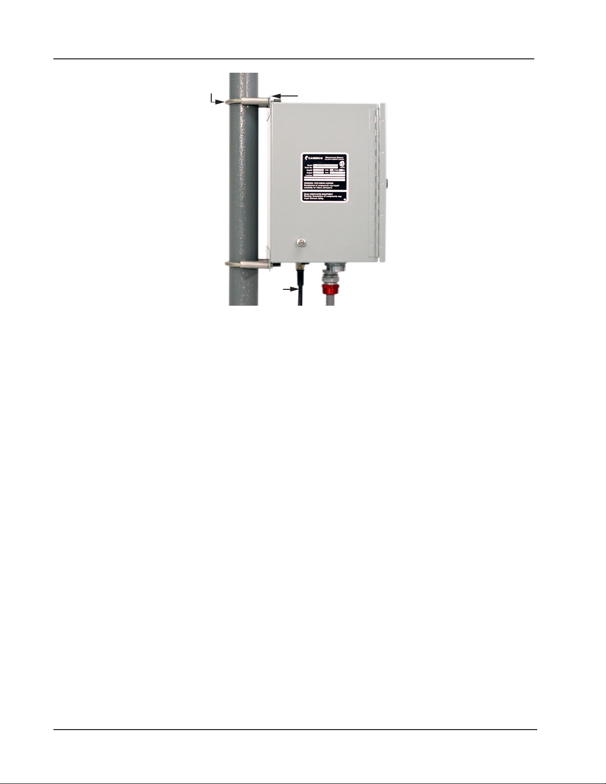
Section 4 Scanner 3100 EFM
U-bolt
(1 of 2)
Figure 4.2—WiFi box mounted on a 2-in. pole
Bulkhead Mount
To mount the WiFi box to a at vertical surface,
Integral mounting
bracket (1 of 2)
Antenna
cable
1. Dry-t the WiFi box and mark screw locations using the outside holes on the top and bottom of the WiFi box integral mounting brackets.
2. Secure the box in place using the screws provided.
Antenna Mount
The antenna must be mounted in a vertical position with the metal base closest to the ground. The antenna connector at
the base of the antenna must be no more than 10 feet from the antenna connector on the bottom of the WiFi enclosure to
accommodate the 10-ft antenna cable.
If the antenna will be mounted to a 2-in. pipe with a 2 3/8-in. OD, an alternate 2-in. pipe bracket must be used in place of
the standard bracket (Figure 4.3, page 73).
To install the antenna,
1. Determine the mounting location and verify that the 10-ft cable will connect to the WiFi box from that location.
2. Position the U-bolts around the pipe and secure to the mounting bracket with the nuts provided.
72
Page 73
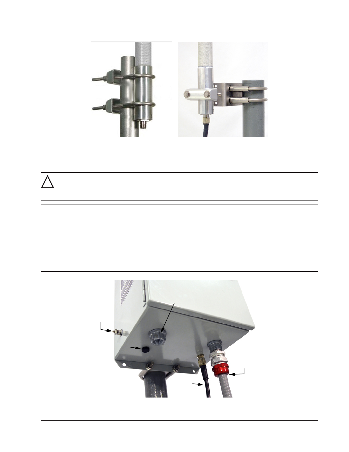
Scanner 3100 EFM Section 4
Figure 4.3—(Left) Standard antenna mounting bracket for outside pipe diameters up to 2-in. and (right) alternate antenna
mounting bracket for outside pipe diameters of 2.375-in.
Wiring the WiFi Box
WARNING: Before attempting any wiring, ensure that all power is disconnected. Failure to disconnect
!
main service power to the WiFi box can cause severe personal injury, death, or substantial property damage. Before reapplying power, ensure that all wiring connections are secure and connected properly.
CAUTION All eld wiring must conform to the National Electric Code, NFPA 70, Article 501-4(b) for installa-
tions within the United States or as specied in Section 18-156 of the Canadian Electrical Code for
installations within Canada. Local wiring ordinances may also apply. All eld wiring must have a
wire range of 22 to 14 AWG and insulation rated for 120 VAC or above and copper or copper-clad
aluminum conductors. Terminal block screws must be tightened to a minimum torque of 5 to 7 in-lb
to secure the wiring within the terminal block. Only personnel who are experienced with eld wiring should perform these procedures.
The instrument must be grounded with a protective earth grounding conductor in accordance with
national and local electrical codes.
External
power
supply inlet
Ground
screw
Vent
Bundled power/
Ethernet cables
(connect to
Scanner 3100)
Antenna
cable
Figure 4.4—Exterior of WiFi box showing location of connectors and external ground screw
73
Page 74
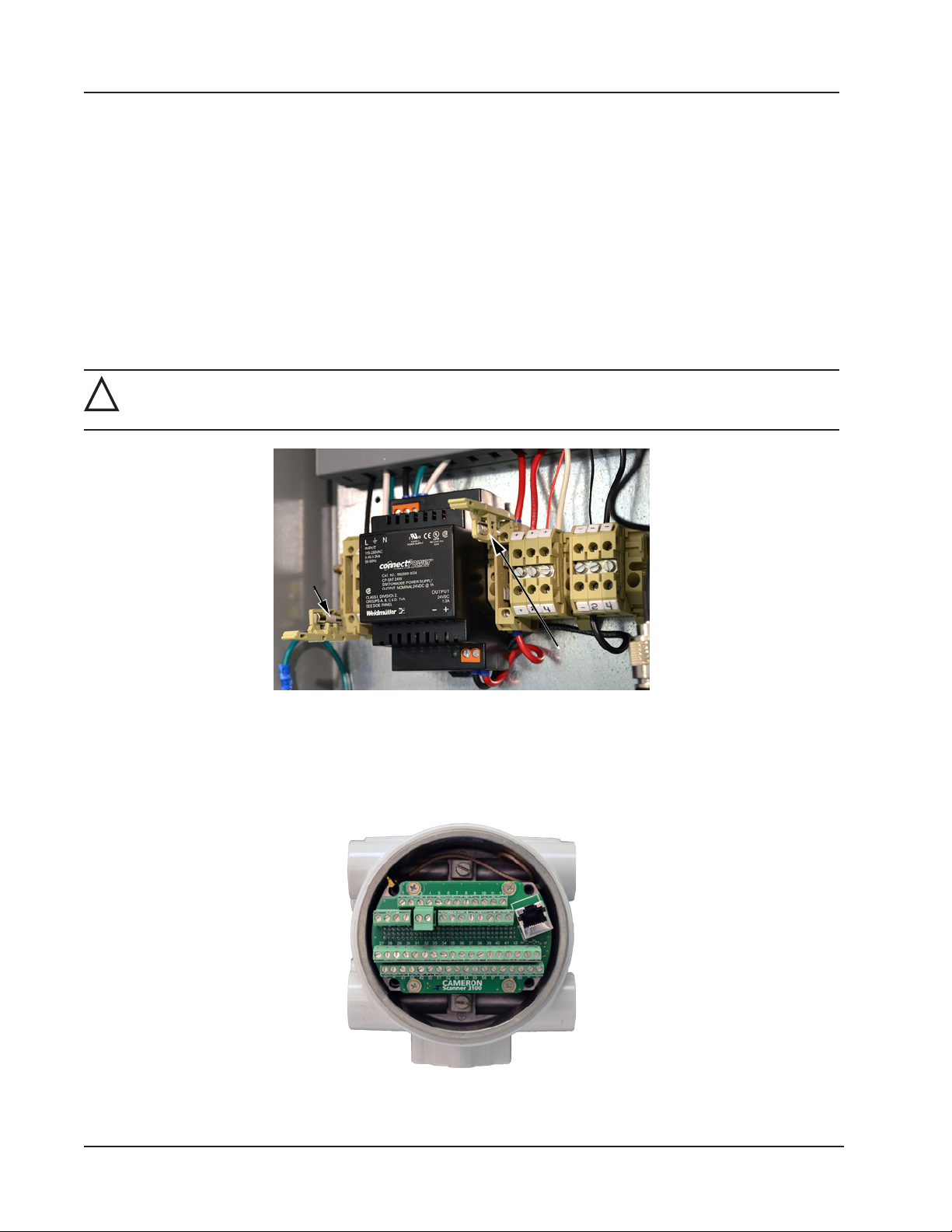
Section 4 Scanner 3100 EFM
To wire the WiFi box for operation, perform the following steps:
1. Open the door of the WiFi box and open the F1 and F2 fuse housings on the power block (Figure 4.5). Fuse F1
opens from the top. Fuse F2 opens from the bottom.
2. Connect a ground wire to the external ground located on the bottom left side of the WiFi box (Figure 4.4, page
73).
3. Disconnect the external power supply that will power the WiFi box using a disconnect breaker switch or other means
of locking out power.
4. Attach the antenna to the WiFi box as follows:
a. Connect the black antenna cable to the antenna connection located on the bottom of the box behind the Ethernet
connection hub as shown in Figure 4.4, page 73.
b. Twist the antenna connector clockwise to tighten.
WARNING: Do not connect/disconnect equipment unless the area is known to be non-hazardous. The
!
Scanner 3100 poses no hazard when opened in a safe area.
F1 fuse
housing
F2 fuse
housing
Figure 4.5—F1 and F2 fuse housing, opened
Connect the Scanner 3100 to the WiFi box as follows:
c. Remove a conduit port plug from the Scanner 3100 enclosure.
d. Remove the rear lid of the Scanner 3100 enclosure to access the terminal board (Figure 4.6).
Figure 4.6—Rear view of Scanner 3100 showing terminal board
74
Page 75
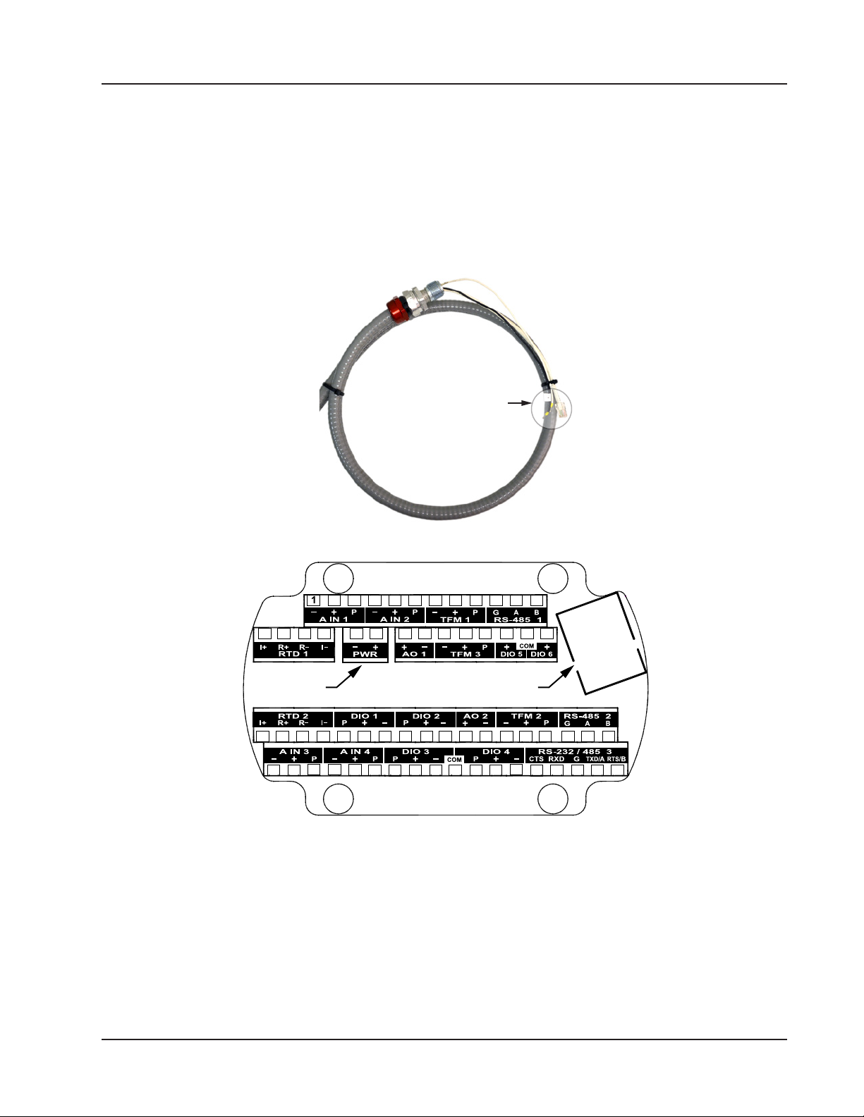
Scanner 3100 EFM Section 4
e. To free up space for pulling wires through the conduit port, unseat the terminal board by unscrewing the four
Phillips screws holding it in place and gently pulling the board straight back to disconnect it from its connected
header without bending pins. Do not attempt to completely remove the board from the enclosure. Doing so
could damage a SATA cable attached to the back of the terminal block. Allow the board to rest terminal-side up
along the bottom edge of the enclosure.
f. Thread the Ethernet and power wires shown in Figure 4.7 through the conduit opening in the Scanner 3100
enclosure and tighten the cable connector in the conduit opening.
g. Connect the Ethernet cable to the Ethernet port on the Scanner 3100 terminal board (shown in Figure 4.8).
Ethernet and
power connectors
Figure 4.7—Ethernet and power conductors connecting the WiFi box to the Scanner 3100
2 3 4 5 6 7 8 9 10 11 12
13 14 15 16 17 18 19 20 21 22 23 24 25 26
Power Ethernet
27 28 29 30 31 32 33 34 35 36 37 38 39 40 41 42 43 44
45 46 47 48 49 50 51 52 53 54 55 56 57 58 59 60 61 62
Figure 4.8—Terminal board illustration showing Ethernet port and Power terminal block location
h. Wire white (+) and black (–) power wires to the Scanner 3100 PWR terminal block (shown in Figure 4.7).
i. Reseat the terminal block in the enclosure, carefully aligning the pins on the back with the underlying header,
and replace the four screws removed in step 4c.
j. Replace the Scanner 3100 enclosure lid.
5. With the external power still off, connect the 110 VAC external power supply to the WiFi box as follows:
a. Thread the external power supply wires through the conduit hub on the bottom of the WiFi box (Figure 4.4,
page 73).
75
Page 76
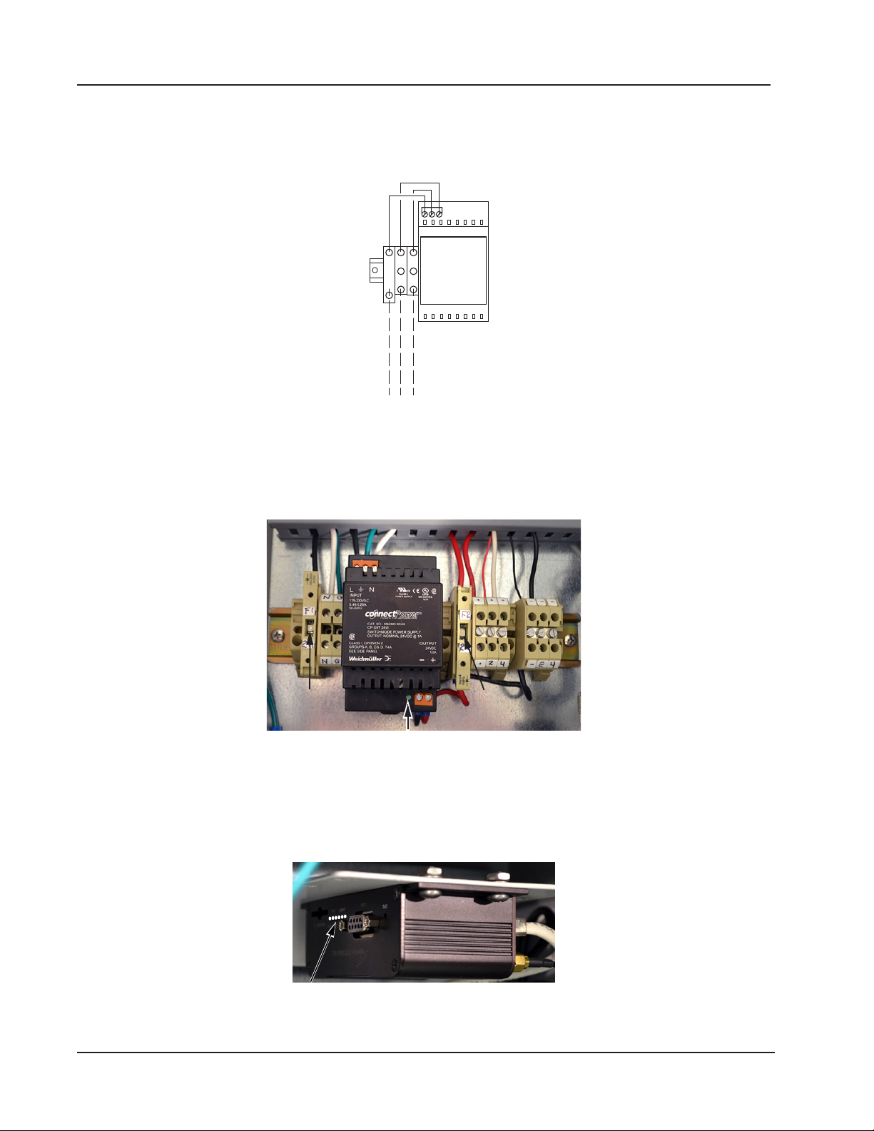
indicator light
Section 4 Scanner 3100 EFM
b. Tighten the power supply cable connector.
c. Verify that the F1 and F2 fuse housings on the power block are open (Figure 4.8, page 75).
d. Wire the external power supply to the designated terminal blocks (H, N, GND) as shown in Figure 4.9.
B W G
F1
H N
GND
110/240 VAC
Figure 4.9—WiFi box external power supply wiring diagram
6. Restore the external power that was disconnected in step 2 to initiate power to the WiFi box.
7. Close the F1 fuse housing (Figure 4.10) to bring power into the box. The green indicator light on the modem power
supply will come on to indicate that the fuse is working correctly.
F1 fuse
diode light
Modem power
F2 fuse
diode light
Figure 4.10—F1 and F2 fuse housing, closed
8. Close the F2 fuse (Figure 4.10) to supply power to the modem and the connected Scanner 3100.
9. Verify that the modem indicator lights are illuminated (Figure 4.11). If no lights are visible, check the diode light in
the middle of the fuse housing (Figure 4.10). If it is lit, the fuse is blown and must be replaced.
Figure 4.11—Location of modem indicator lights
76
Page 77

Scanner 3100 EFM Section 4
Connecting to the Scanner 3100
The WiFi modem is pre-congured at the factory to expedite user setup in the eld. To connect to the Scanner 3100 web
interface via the WiFi accessory,
1. Apply 110 VAC power to the modem. The modem will begin broadcasting its wireless signal momentarily.
2. From a laptop or other browser-enabled device, click on the “IPn4G+” wireless connection to connect to the WiFi
modem.
3. Locate and record the IP address displayed in the upper left corner of the Scanner’s LCD display.
4. Open a web browser on the laptop or other browser-enabled device and enter the Scanner 3100 IP address. The
Scanner 3100 web interface Device Login page will appear.
5. On the Device Login page, enter the appropriate user name and password. Default entries (case-sensitive) are:
User Name: admin
Password: scanner
6. Press the “Login” button on the screen.
Note If the loading stalls, click Refresh. If a connection to the Scanner is not established, verify the IP address and
repeat step 4.
Important Changing the administrative password after the initial login is strongly recommended. See the
“Security” section of the Scanner 3100 Web Interface User Manual for instructions on changing the
administrative password and setting up additional users with password-protected access.
Troubleshooting the Wireless Connection
If the modem fails to communicate with the Scanner 3100, consider the following steps to address the problem:
1. Open and close fuse F2 inside the WiFi box to reboot the modem.
2. Shut off the laptop and restart it.
3. If the modem is powered, but no wireless connectivity is detected on your computer or other browser-enabled
device, it may be necessary to reset the Scanner 3100 IP address. Please contact Cameron technical support for
assistance.
Adding Security to the WiFi Connection
WiFi security is disabled at the factory during initial modem conguration, but users can enable security by logging into
the modem web browser menu, as follows.
1. Open a web browser on a laptop or smartphone.
2. Enter the modem’s IP/port address, 192.168.168.1:8080.
3. When prompted, enter the following user name and password to access the main modem screen:
User Name: admin
Password: admin
4. Click the Wireless tab in the top bar, and the Radio 1 tab from the second bar at the top of the screen.
5. From the Radio 1 tab, locate the “Encryption Type” eld near the bottom of the screen.
6. Select an encryption type from the dropdown list.
7. Enter a password if desired, and click Submit.
77
Page 78

Section 4 Scanner 3100 EFM
This page intentionally left blank.
78
Page 79
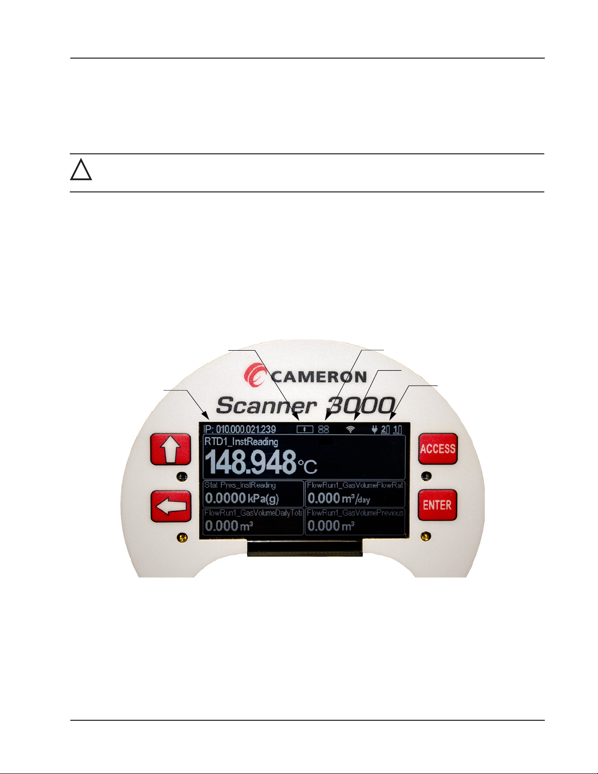
Battery/Power
Indicators
Wireless Glyph
Keypad Glyph
IP Address
LCD Display Indicator
Scanner 3100 EFM Section 5
Section 5—Display and Keypad Operations
The Scanner 3100 display and keypad allows you to view the real-time measurements for up to 32 selected parameters,
5 at a time. By default, the parameters scroll continuously through the 5 elds provided (Figure 5.1). In a declassied or
safe area, you can use the keypad to manually pace the display. To access the keypad, remove the cover of the explosionproof enclosure.
WARNING: To prevent ignition of hazardous atmospheres, do not remove the cover while circuits are
!
alive. The Scanner 3100 poses no hazard when opened in a safe area.
IP Address
The IP address used to connect with a Scanner 3100 via the web interface is displayed at the top of the LCD. The IP address is assigned when a user connects to the device for the rst time using a computer or other browser-enabled device.
If no address appears in the display, check for a problem with the Ethernet connection.
Status Indicators (Glyphs)
When power is applied to the device, a row of pictorial status indicators or “glyphs” appears in the top right corner of the
LCD. You can use these glyphs to quickly assess the status of the LCD display, wireless connectivity, power connectivity, and battery capacity once you become acquainted with the symbols and their meanings (Figure 5.1 and Table 5.1—
Device Status Glyph Denitions, page 80).
Figure 5.1—LCD display components
Additionally, glyphs indicating the parameter status appear to the left of the parameter reading. You can use these glyphs
to quickly identify the status of a parameter (fail, locked, high- or low-system alarm, etc.) See Table 5.2—Parameter Sta-
tus Glyph Denitions, page 81 for more information about the parameter status glyphs.
79
Page 80

Section 5 Scanner 3100 EFM
Table 5.1—Device Status Glyph Denitions
Keypad Use. This glyph depicts the four keys positioned on either side of the LCD. Pressing a key
on the keypad causes the corresponding key in the glyph to appear lled, verifying that the key is
actuated.
Device Boot-up Failure. The illumination of all four keys in the keypad glyph when no keys are
depressed signals a boot failure. Should this occur, the LEP and UIC rmware versions will appear as
“0.000” in the web interface (Device menu), and the communication ports and turbine inputs will not
function properly.
To rule out a hardware failure:
1. Remove all power sources and unplug power at the terminal block.
2. Let the device sit idle for at least 10 seconds.
3. Check the power supply to ensure it complies with the Scanner’s external power supply rating.
4. Restore power and check the keypad glyph. If the four quadrants are still illuminated, contact
Cameron for assistance.
LCD Display Indicator (Center/Asleep). The default mode for the LCD display indicator.
LCD Display Indicator (Right). Cover the right half of the LCD display to stop auto-scrolling
parameters and begin advancing parameters manually.
LCD Display Indicator (Left). Cover the left half of the LCD display to view the device name, rmware
version, serial number, metrology hash codes, and the IP address.
External Power. An external power source has been detected.
Battery Status. These numbered glyphs represent the Scanner 3100’s two lithium battery packs. The
left-most indicator represents the battery on the left as you face the display. Each glyph provides two
indications.
Battery Capacity The tall battery shape indicates battery capacity. A lled “battery pack” (black
on a light gray background) indicates full capacity. An empty “battery pack”
indicates a nearly depleted battery pack or none installed. Battery replacement
is recommended when the indicator shows capacity to be 50% or less. Battery
levels typically remain high (full) for the majority of a battery’s life and then
deplete quickly near the end of the battery’s life.
Battery State
(In Use or Not in
Use)
A lled block under the number indicates the battery is in use. One or both
batteries may be in use at any given time. When external power is available,
neither battery block should appear lled. If a mostly depleted battery is shown
to be in use when you are ready to replace it, you may proceed without concern.
The Scanner 3100 will automatically switch to the remaining battery pack when
one pack is disconnected from the device. To avoid interrupting operations: If
both batteries are nearly depleted, connect an external power source before
disconnecting the battery pack(s) for replacement. If external power is not
available and at least one installed battery pack has the capacity to power the
device momentarily, disconnect and replace the fully depleted pack before
disconnecting and replacing the second pack.
80
Page 81
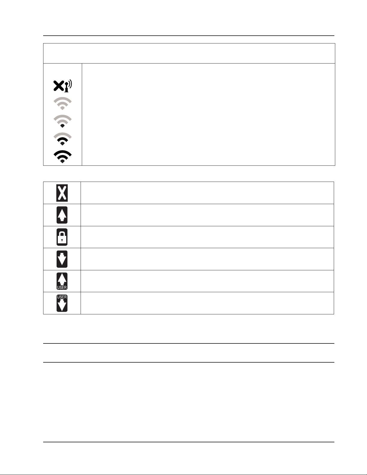
Scanner 3100 EFM Section 5
Table 5.1—Device Status Glyph Denitions
Wireless Communications Status.
The wireless transmitter is disabled.
No mesh nodes are congured.
At least one mesh node is congured but none are operational.
One or more mesh nodes are congured and at least one is operational.
Multiple mesh nodes are congured and all are operational.
Table 5.2—Parameter Status Glyph Denitions
Fail. This parameter value is in a fail state.
High System Alarm. The parameter value exceeds the top end of the system operating range.
Locked. The parameter is in Maintenance mode, or is congured to use a user-specied override
value.
Low System Alarm. The parameter value is below the low end of the system operating range (low
end).
High User-Configured Alarm. The parameter value exceeds the user-congured high setpoint.
Low User-Configured Alarm. The parameter value is below the user-congured low setpoint.
Congurable Display Features
A number of display features can be congured via the Scanner 3100 web interface with the proper user permissions.
Note Only users with Administrator or Conguration Editor user access levels can change display features. See the
Scanner 3100 Web Interface User Manual for instructions on setting user security levels.
• Orientation. By default, display orientation is set to “automatically detect” the orientation of the device. If the
device is inverted, the display will automatically invert as well for optimum visibility. A user can also specify the
orientation of the MVT port as upward or downward.
• Color Scheme. The LCD display background can be congured as light gray or dark gray. Character color
automatically adjusts to provide contrast for easy viewing.
• Message Delay. This setting determines the length of time a set of parameters is displayed between scrolls. The
default setting is 10 seconds. The congurable range of values is 0 to 600 seconds (10 minutes).
81
Page 82
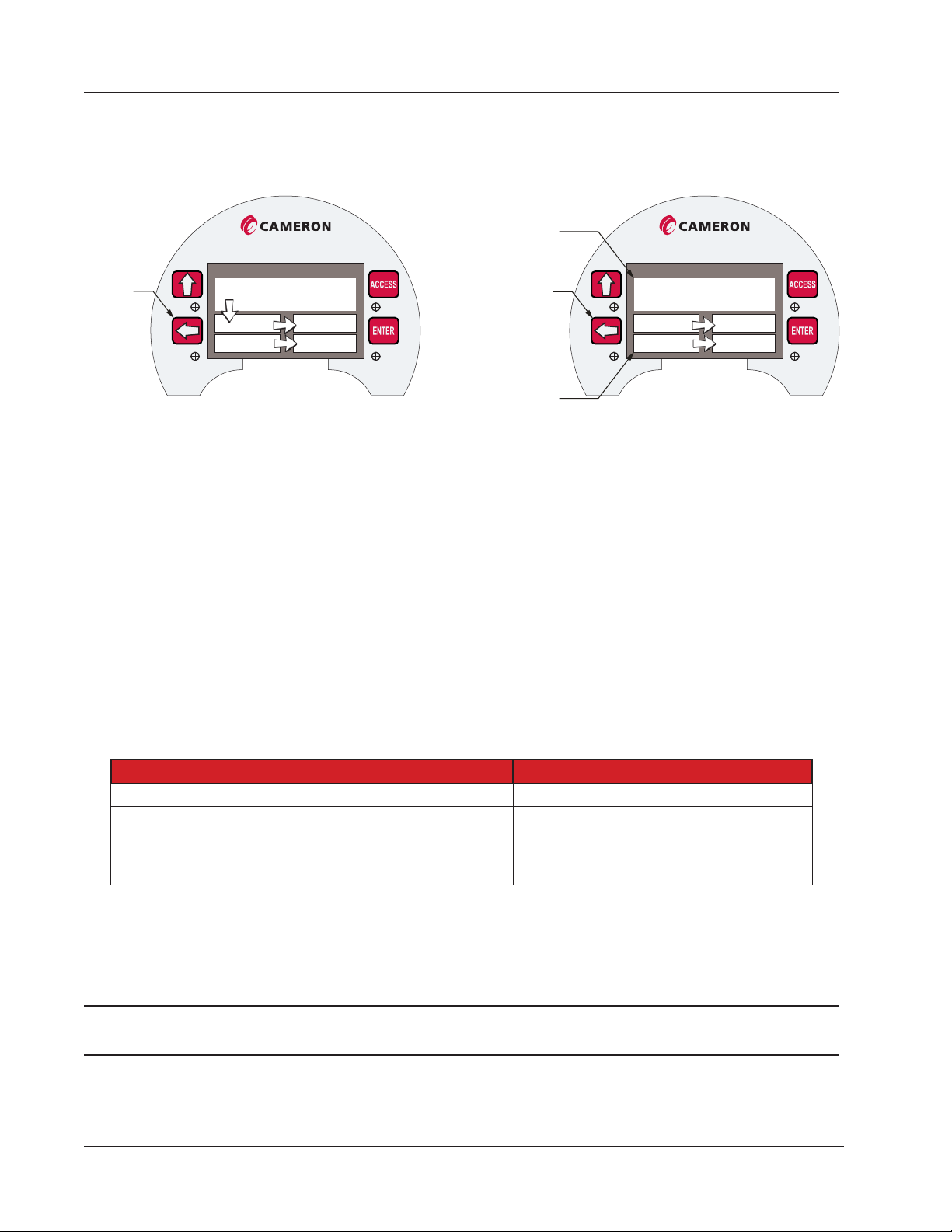
the four fields in the bottom half
View next
parameter
Section 5 Scanner 3100 EFM
Message Display Mode
You can force selected “high priority” parameters to be displayed only in the top eld of the display by assigning a priority status to these parameters (Figure 5.2).
Parameters configured
Scanner 3000
as “topmost” will always be
displayed in the top field
Scanner 3000
Position 1
2 3
4 5
Figure 5.2—Arrangement of parameters in LCD display
View next parameter
Parameters configured
as “normal” will scroll through
“topmost” parameter(s)
1 2
3 4
Figure 5.2, page 82 shows the standard order of progression as parameters cycle through ve display elds on the
LCD. You may choose to restrict the large topmost display eld for displaying high-priority parameters that require constant monitoring. When one or more parameters are congured as “topmost” priority in the web interface, the display
effectively functions as two parallel scrolling sequences. The large “topmost” eld will scroll the high priority parameters and the bottom four elds will scroll the other normal priority parameters. If only one parameter is congured as
“topmost” priority, it will remain in constant view in the top display. For additional message display modes, refer to the
Scanner 3100 Web Interface Manual.
Keypad Controls
Using the keypad buttons, a user can manually pace the Scanner 3100 display, locate its serial number and rmware version, and view communications settings. Table 5.3—Keyboard Controls identies the button-press congurations for
performing these tasks.
Table 5.3—Keyboard Controls
Keyboard Control Action
Stop scrolling and advance parameters manually Press LEFT ARROW or COVER RIGHT
View device name, rmware version, serial number, metrology
hash codes, IP address
View serial port conguration settings (including protocol,
baud rate, slave address, unit ID)
COVER LEFT
Press ACCESS
LCD Display Indicator
To change the LCD display view, leave the enclosure lid in place and cover the right side or left side of the LCD with
your hand for 4 to 8 seconds, after which the device should detect your hand. Upon detection, the Scanner window will
display a popup window with the device information.
Note When covering the LCD display, there is no need to touch the LCD glass or to completely block your view of the
LCD.
When the LCD Display Indicator changes position from the center to the left, the device name, rmware version, serial
number, metrology hash codes, and IP address will appear. The metrology device and software codes are 32-bit values
82
Page 83
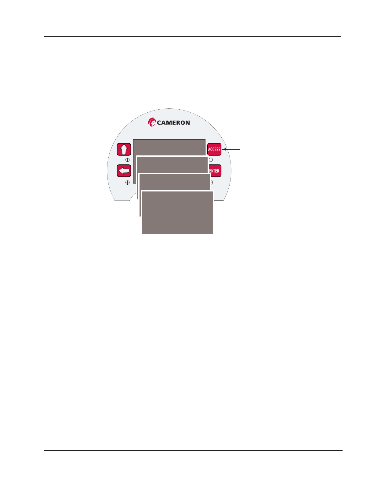
Scanner 3100 EFM Section 5
contained within the binary le loaded onto the Scanner 3100. The codes uniquely dene the device rmware and software to ensure that the rmware has not been modied.
Cover the right side of the LCD to stop automatic scrolling and enable manual pacing through the device parameters.
Viewing Communication Settings
Press the ACCESS key to display the communication port settings, beginning with Serial Port 1 (Figure 5.3). The display
will momentarily progress to the settings for the other serial port settings.
Scanner 3000
Serial Number:
Firmware Version: 1.001
Serial Port 1: Modbus Enron
Baud: 9600 Add: 1
Serial Port 2: Modbus Master
Serial Port 3: Modbus TCP
Baud: 9600 UID: 1
Figure 5.3—Communication parameters accessible via the Access key
View
communication
settings
83
Page 84

Section 5 Scanner 3100 EFM
This page intentionally left blank.
84
Page 85
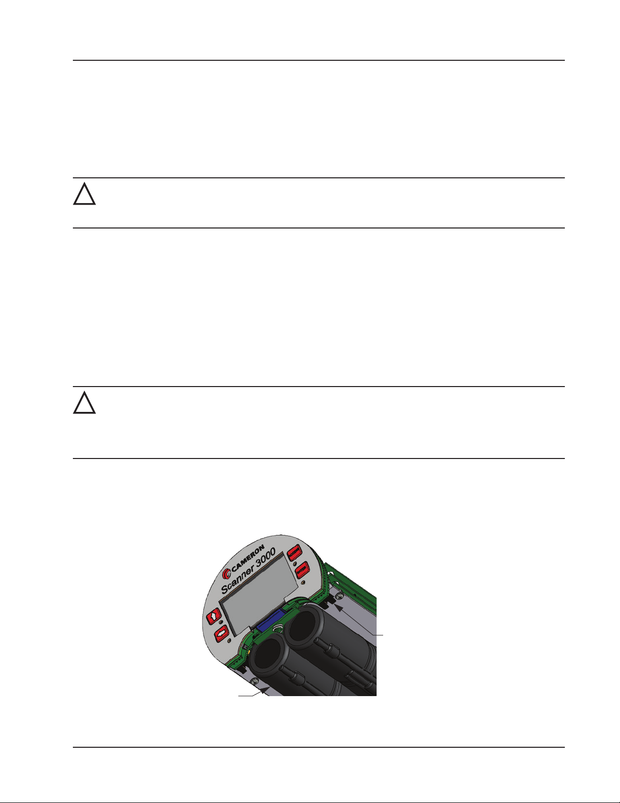
connector (2)
pack (2)
Scanner 3100 EFM Section 6
Section 6—Scanner 3100 EFM Maintenance
The Scanner 3100 is engineered to provide years of dependable service with minimal maintenance. Batteries require periodic replacement, and battery life depends on (1) whether battery power is the primary or secondary power source, (2)
the conguration settings of the Scanner 3100, and (3) ambient temperature conditions.
All conguration settings are stored in nonvolatile memory; therefore, conguration settings will not be lost in the event
of power failure.
WARNING: Before servicing the Scanner 3100, disconnect all power sources/signal sources or verify that
!
the atmosphere is free of hazardous gases. Do not remove the cover while circuits are alive. The Scanner
3100 poses no hazard when opened in a safe area.
Lithium Battery Pack Replacement
Two integral battery packs provide backup power for the Scanner 3100 when external power is present, and can sustain
the device for short periods as an autonomous power supply. Battery life can vary, depending on the power demands of
the conguration. As an autonomous supply, the dual battery packs have an estimated life of 2 to 3 weeks, assuming the
device is congured with a base load.
A battery capacity indicator in the Scanner 3100 display helps users predict the need for battery replacement. See Table
5.1—Device Status Glyph Denitions, page 80, for details. Battery replacement is recommended when the indicator
shows capacity to be 50% or less. Battery levels typically remain high (full) for the majority of a battery’s life and then
deplete quickly near the end of the battery’s life.
When two packs are installed, a user can replace a spent battery pack without interrupting operations.
WARNING: The lithium battery pack that powers the Scanner 3100 is a sealed unit; however, should a lithi-
!
um battery develop a leak, toxic fumes could escape upon opening the enclosure. Ensure that the instrument is in a well-ventilated area before opening the enclosure to avoid breathing fumes trapped inside the
enclosure. Exercise caution in handling and disposing of spent or damaged battery packs. See additional
information in Lithium Battery Disposal, page A-1.
Replacement Procedure
The stick-style battery packs are installed in a compartment just below the display (Figure 6.1). Battery leads are connected to the Scanner 3100 via two connectors extending from the back side of the display assembly on either side of the
rounded cutout.
Battery pack
Battery
Figure 6.1—Removal of the battery pack from the enclosure
85
Page 86

Section 6 Scanner 3100 EFM
To replace a Scanner 3100 lithium battery pack,
1. Remove the cover from the enclosure (after securing the area per the warning on the previous page).
Note Proceed carefully when connecting the battery packs to the plastic receptacles to avoid damaging the connector
or bending pins. Using a pair of needle-nose pliers to grasp the plastic battery cable connector may aid in aligning the connector and receptacle pins when connecting and disconnecting battery packs.
2. Disconnect the battery leads of the spent battery from the connector on the back side of the display assembly.
3. Firmly grasp the battery pack and gently pull it forward to remove it from the enclosure.
4. Insert the fresh battery pack so that the battery lead end faces the rear of the battery compartment.
5. Connect the lead to the connector on the back side of the display assembly.
6. Repeat steps 2 through 5 to replace the other battery pack if required. Even if no external power is supplied, operations will continue uninterrupted as long as one battery pack remains connected.
7. Replace the enclosure cover.
86
Page 87
Scanner 3100 EFM Section 7
Section 7—Scanner 3100 Parts
Spare Parts and Optional Hardware
The stick-style lithium battery packs, the lithium coin cell battery that controls the real-time clock, and the desiccant
packets are the only consumable parts within the Scanner 3100 that require periodic replacement. If a WiFi communication accessory is in use, fuses may be replaced periodically as well.
Lithium coin cell batteries can last 8 years or longer, depending on operating conditions. Keeping a spare battery on hand
can prevent the loss of the device time and date in the event the coin cell battery fails.
WARNING—EXPLOSION HAZARD: Substitution of components may impair suitability for Class I, Division
!
1. Use of spare parts other than those identied by Cameron International Corporation voids hazardous
area certication. Cameron bears no legal responsibility for the performance of a product that has been
serviced or repaired with parts that are not authorized by Cameron.
Table 7.1—Scanner 3100 EFM Parts
Qt y. Part Number Description
Common Parts
1* 9A-100002605 Desiccant, Humidisorb, Self Regenerate, 2 in. x 2 in. Packet with Adhesive
1 3J-40-0245-00 Battery, BR 2032, 3 V, 190 mAh, Lithium Coin
1 76526610 Connector, Power, 2-pin, Connects to the Terminal Strip
2 76525511 O-Ring, 120 mm × 4 mm, XD-I, for Explosion-proof Enclosures
1 502 68179 Kit, Pole Mount, Stainless Steel
1 50263697 CD, Scanner Software (ModWorX Pro, Scanner Data Manager, ScanMap, and
ScanFlash Software); software is also available for download from the Cameron
website
For wireless components, see Table 7.2—Wireless Components, page 88.
CSA-Approved Parts
1 9A-21-XX-YY
(see Table 7.3—RTD
and Cable Assemblies,
page 89)
1* 50261533 Battery Pack, 2 D Batteries in Series, 7.2 V, Lithium, Stick Style, CSA-approved
1 50267637 Assembly, External Explosion-proof Switch, with Extension, CSA-approved,
1 50271475 Assembly, External Explosion-proof Switch, with Extension, CSA-approved, Fits
1 50267636 Assembly, External Explosion-proof Switch, with Extension, CSA-approved, Fits
1 50271474 Assembly, External Explosion-proof Switch, with Extension, CSA-approved Fits
Assembly, RTD and Cable, CSA Explosion-Proof (Division 1), Model 21
Fits 3/4 in. Female Pipe Thread, Momentary Contact, Wired Ends (uses include
manual control of ow accumulation, and manual control of a triggered archive)
3/4 in. Female Pipe Thread, Momentary Contact, with Lockout Mechanism, Wired
Ends (uses include manual control of ow accumulation or manual control of a
triggered archive)
3/4 in. Female Pipe Thread, Toggle, Wired Ends (uses include pacing the display,
toggling a wireless transmitter on and off, resetting grand totals for ow run or
pulse input accumulations, unlatching a digital output, and resetting a latch on a
triggered archive)
3/4 in. Female Pipe Thread, Toggle, with Lockout Mechanism, Wired Ends (uses
include pacing the display, toggling a wireless transmitter on and off, resetting
grand totals for ow run or pulse input accumulations, unlatching a digital output,
and resetting a latch on a triggered archive)
87
Page 88
Section 7 Scanner 3100 EFM
Table 7.1—Scanner 3100 EFM Parts
Qt y. Part Number Description
ATEX-Approved Parts
1 9A-X-TTXR-0003 Assembly, RTD and Cable, Flameproof, 3500-mm Cable, 50-mm Probe,
ATEX-approved, for Line Sizes from 2 to 12 inches
1 50302004 Battery Pack, 2 D Batteries in Series, 7.2 V, Lithium, Stick Style, ATEX-approved
1 50302001 Assembly, External Explosion-proof Switch, with Extension, ATEX-approved,
Fits 3/4 in. Female Pipe Thread, Momentary Contact, Wired Ends (uses include
manual control of ow accumulation, and manual control of a triggered archive)
1 50302003 Assembly, External Explosion-proof Switch, with Extension, ATEX-approved, Fits
3/4 in. Female Pipe Thread, Momentary Contact, with Lockout Mechanism, Wired
Ends (uses include manual control of ow accumulation or manual control of a
triggered archive)
1 503019 98 Assembly, External Explosion-proof Switch, with Extension, ATEX-approved, Fits
3/4 in. Female Pipe Thread, Toggle, Wired Ends (uses include pacing the display,
toggling a wireless transmitter on and off, resetting grand totals for ow run or
pulse input accumulations, unlatching a digital output, and resetting a latch on a
triggered archive)
1 50302000 Assembly, External Explosion-proof Switch, with Extension, ATEX-approved Fits
3/4 in. Female Pipe Thread, Toggle, with Lockout Mechanism, Wired Ends (uses
include pacing the display, toggling a wireless transmitter on and off, resetting
grand totals for ow run or pulse input accumulations, unlatching a digital output,
and resetting a latch on a triggered archive)
* Recommended spare part
** For router adapters with other voltage ratings, contact Cameron.
Table 7.2—Wireless Components
Qt y. Part No. Description
1 76533628 Antenna Coupler, N Coax, Male-to-Male (Female Thread), ATEX-approved
1 2350765-01 Antenna Coupler, N Coax, Male-to-Male (Female Thread), CSA-approved
1 2350869 -01 Antenna, Short-haul Wireless, 2.4 GHz, 1/2 Wave Dipole, N Male, Right-Angle
1 50279275 Antenna, Short-Haul Wireless, Remote-Mount, 9 dBi 2.4 GHz Omnidirectional,
32-in. long, N Female with pole-mount bracket (ts pole outside diameters up to
2- in.)
1 50278052 Bracket, Pipe-Mount for Remote-Mount Antenna (ts pipe with 2.375-in. outside
diameter)
1 76 5 27410 Antenna Cable with Connectors, Short-haul Wireless, 10-ft, Type 400,
-40 degC to 70 degC (–40 degF to 158 degF)
1 76527411 Antenna Cable with Connectors, Short-haul Wireless, 20-ft, Type 400,
-40 degC to 70 degC (–40 degF to 158 degF)
1 76 5 27412 Antenna Cable with Connectors, Short-haul Wireless, 30 -ft, Type 400,
-40 degC to 70 degC (–40 degF to 158 degF)
1 50272454 Ethernet Router, Portable, USB-powered; 110 V/220 V-to-USB Adapter Included
(not required when PC-powered with USB cable)**
1 76528845 Ethernet Router, Portable, Integral Rechargeable Lithium-Ion Battery-powered
1 76528309 RJ-45 Ethernet Cable, 15-ft Molded Connector
1 50272960-05 Cable, Ethernet, 5 ft, for WiFi Communications Accessory for Multi-Scanner Sites
1 50272960-10 Cable, Ethernet, 10 ft, for WiFi Communications Accessory for Multi-Scanner Sites
1 50272960-20 Cable, Ethernet, 20 ft, for WiFi Communications Accessory for Multi-Scanner
Sites
88
Page 89
Scanner 3100 EFM Section 7
Table 7.2—Wireless Components
Qt y. Part No. Description
1 50272960-30 Cable, Ethernet, 30 ft, for WiFi Communications Accessory for Multi-Scanner
Sites
2* 9A -0111 - 9 00 7 T Fuse, 5 amp, 5 × 20, Glass, for WiFi Communications Accessory for Multi-Scanner
Sites
2 9A-0142-9 003T Assembly, Clamp and U-Bolt, 2-1/2 in., for WiFi Communications Accessory for
Multi-Scanner Sites
* Recommended spare part if WiFi Communications Accessory is in use
Table 7.3—RTD and Cable Assemblies
Select assemblies based on specic application.
Cable length and probe length are specied in the part number:
9A-21-XX-YY where XX is the cable length and YY is the probe length.
Available cable lengths: 5, 10, or 30 ft. Probe nominally adjustable up to 6 in. or 12 in.
Qt y. Part No. Description
1 9A-21-05-06 Model 21 RTD, CSA Explosion-proof, 5-ft Cable, 7.625-in. Probe for 6 -in.
Thermowell
1 9A -21- 0 5 -12 Model 21 RTD, CSA Explosion-proof 5-ft Cable, 11.625-in. Probe for 12-in.
Thermowell
1 9A -21-10-06 Model 21 RTD, CSA Explosion-proof 10-ft Cable, 7.625-in. Probe for 6-in.
Thermowell
1 9A -21-10-12 Model 21 RTD, CSA Explosion-proof 10-ft Cable, 11.625-in. Probe for 12-in.
Thermowell
1 9A-21-30-06 Model 21 RTD, CSA Explosion-proof 30-ft Cable, 7.625-in. Probe for 6-in.
Thermowell
1 9A -21- 30-12 Model 21 RTD, CSA Explosion-proof 30-ft Cable, 11.625-in. Probe for 12-in.
Thermowell
The thermowell dimensions listed above refer to the maximum “U” dimensions that a probe will fit with a plastic bushing.
Consult Cameron for sizing information if a union and nipple is to be used in place of a bushing. When using a bushing,
select the shortest probe possible for a compact installation and best strength.
Electronics Replacement
The Scanner 3100 contains two circuit board subassemblies (pre-assembled groupings of circuit boards and hardware),
a terminal board, and an optional advanced communications board (for support of wireless communications) that can be
replaced by a knowledgeable technician. For disassembly instructions, see the Scanner 3100 Service User Manual. Subassemblies must be replaced without further disassembly.
Before attempting any repair work on a Scanner 3100, contact a Cameron technician to review the issues you are observing and determine if the problem requires hardware replacement.
CAUTION—EQUIPMENT DAMAGE RISK: Attempts to disassemble the Scanner 3100 in the eld for the
!
purpose of troubleshooting or repairs can damage the internals and cables beyond repair. Cameron does
not warranty damage resulting from eld replacement of Scanner 3100 parts.
Table 7.4—Scanner 3100 Circuit Board Replacements
Qt y. Part Number Description
1 50279707 Display Subassembly, includes Hardware Kit and Coin Cell Battery
89
Page 90
Section 7 Scanner 3100 EFM
Table 7.4—Scanner 3100 Circuit Board Replacements
Qt y. Part Number Description
1 50279704 Main Subassembly, includes Hardware Kit and SATA Cable (Field replacement in
devices equipped with an MVT can result in accuracy degradation.)
1 2350508-01 Terminal Board
1 50279738 Advanced Communications Board, CSA
1 50331936 Advanced Communications Board, ATEX
1 76522730 Cable, SATA, 300 mm, Straight with Latch
1 50279708 Hardware Kit (includes screws and standoffs for subassemblies)
90
Page 91

Scanner 3100 EFM Appendix A
Appendix A—Lithium Battery Information
Lithium Battery Disposal
Once a lithium battery is removed from a device and/or is destined for disposal, it is classied as solid waste under EPA
guidelines. Depleted lithium batteries are also considered to be hazardous waste because they meet the denition of Reactivity, as per 40 CFR 261.23(a)(2), (3) and (5). This document describes how the lithium reacts violently with water,
forms potentially explosive mixtures with water, and when exposed to certain pH conditions, generates toxic cyanide or
sulde gases.
Federal law requires that depleted lithium battery packs be sent to a fully permitted Treatment, Storage and Disposal Facility (TSDF) or to a permitted recycling/reclamation facility.
Important Do not ship lithium battery packs to our factory. Cameron facilities are not permitted recycling/rec-
lamation facilities.
CAUTION Proling and waste characterization procedures must be followed prior to shipping a lithium bat-
tery to a disposal site. It is the shipper’s responsibility to comply with all applicable federal transportation regulations (see below).
Transportation Information
WARNING: The Scanner 3100 contains lithium batteries. The internal component (thionyl chloride) is haz-
!
ardous under the criteria of the Federal OHSA Hazard Communication Standard 29 CFR 1920.1200. Before
shipping a lithium battery or equipment containing a lithium battery, verify that the packaging and labeling conforms with the latest version of all applicable regulations.
The transport of the lithium batteries is regulated by the United Nations, “Model Regulations on Transport of Dangerous
Goods,” (special provisions 188, 230, and 310), latest revision.
Within the United States, the lithium batteries and cells are subject to shipping requirements under Part 49 of the Code of
Federal Regulations (49 CFR, Parts 171, 172, 173, and 175) of the US Hazardous Materials Regulations (HMR), latest
revision.
Shipping of lithium batteries in aircraft is regulated by the International Civil Aviation Organization (ICAO) and the International Air Transport Association (IATA) requirements in Special Provisions A45, A88 and A99, latest revision.
Shipping of lithium batteries on sea is regulated the International Maritime Dangerous Goods (IMDG) requirements in
special provisions 188, 230 and 310, latest revision.
Shipping of lithium batteries on road and rail is regulated by requirements in special provisions 188, 230 and 310, latest
revision.
Battery Safety Datasheet
For a link to the current MSDS for the lithium batteries used to power the Scanner 3100, see the Valves & Measurement
section of the our website: www.cameron.slb.com/owcomputers.
A-1
Page 92

Appendix A Scanner 3100 EFM
This page intentionally left blank.
A-2
Page 93

Scanner 3100 EFM Appendix B
Appendix B—FTP Downloads
FTP downloads provide an alternative to the web interface download process and may be preferred for expediting downloads, particularly if you have no other need to log into the web interface. FTP downloads can be performed with a router
connection to the Scanner, or with a physical Ethernet cable connection between the PC/laptop and the Scanner. The only
piece of information required is the IP address of the Scanner 3100 storing the archive les.
The following steps describe the FTP download process using the Windows FTP Command executable le.
Important Other third-party FTP le managers, such as File Commander, provide a graphical interface. Please
note that the Scanner 3100 currently supports only one FTP session at a time; some software programs require two simultaneous sessions to function properly.
Downloading SDF Files from the Scanner 3100
To download SDF les using Windows FTP Command prompts, perform the following steps:
1. Access the Command Prompt window by clicking the Start button.
2. Type cmd and click Enter.
3. Type ftp <IP address of the Scanner 3100 device> and click Enter.
4. At the prompt, type <your login name> and click Enter.
5. At the prompt, type <your login password> and click Enter.
6. Type cd archives and click Enter to access the parent level of the directory. This directory contains three folders
of SDF les: full, recent, and events.
7. Type cd <file type> (for example, cd full to select the full folder) and click Enter.
8. Type ls or dir to view a list of .sdf les inside the folder. The command “dir” provides additional details about the
les such as archive timestamp and le size.
9. To download an .sdf le, type get <complete filename> c:<location for saving the SDF
file > and click Enter.
10. To download a batch of .sdf les, type bye to exit the connection. The command prompt will display your default
directory. Unlike the single le download process where you can specify the desired location of the download les
as part of the command string, batch downloads require you to establish the intended location before the download
command it issued.
11. If the current directory is not where the SDF les are to be stored, type cd <desired directory path for
storing SDF files> and click Enter.
12. Type cd archives\<file type> (for example, cd archives\full) and click Enter.
13. Type prompt and click Enter.
14. Type m ge t <*.s df > and click Enter. The batch of les should automatically be transferred to the directory path
designated in step 11.
Note FTP clients are prone to timeouts. To restart following a timeout, type open <Scanner IP address>.
Note To move back one level in your directory path, type cd ..
B-1
Page 94
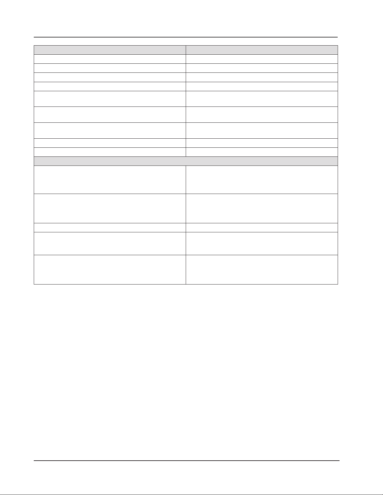
Appendix B Scanner 3100 EFM
Full Folder Contents Example Filename
Daily Logs: Scanner 3100 S3100_FA01_D_Full.sdf
Interval Logs: Scanner 3100 S3100_FA01_I_Full.sdf
Triggered Logs: Scanner 3100 DeviceName_TR_Full.sdf
Daily Logs: Scanner Slave Device (up to 20 logs possible) Slave01_SA01_D_Full.sdf
Interval Logs: Scanner Slave Device (up to 20 logs
possible)
Local (All archive logs for the Scanner 3100 only, includes
no logs for networked slave devices)
Complete (Complete archive record for the Scanner 3100
and networked slave devices)
Event Logs: Scanner 3100 S3100_EA _Full.sdf
Event Logs: Scanner Slave Device Slave01_SE01_Full.sdf
File Name Conventions
Scanner 3100 Daily or Interval Logs Example: S3100_FA01_D_Full.sdf, where
Slave Device Daily or Interval Logs Example: Slave01_SA01_D_Full.sdf, where
Scanner 3100 Event Archive Example: S3100_EA_Full.sdf, where EA = Event Archive
Slave Device Event Archive Slave01_SE01_Full.sdf, where
Scanner 3100 Recent Logs (interval logs recorded within
current 24-hour contract period)
Slave01_SA01_I_Full.sdf
S3100_Local.sdf
S3100_Complete.sdf
FA01 = ow archive (FA01 or FA02) and
D = type of log (D for daily or I for interval)
Slave 01 = slave ID (up to 20 possible),
SA01 = slave archive (one for each slave device) and
D = type of log (D for daily or I for interval)
SE01 = slave archive (one for each slave device) and
EA = Event Archive
S3100_FA01_I_20140823.sdf, where
FA01 = ow archive (FA01 or FA02),
I = type of log (D for daily or I for interval) and
20140823 = date stamp (year-month-day)
Slave Device Archive Logs
Slave archive logs can also be downloaded locally from a Scanner 2000, 2100 or 2200 using ModWorX™ Pro software.
Viewing and Sharing Downloaded Data
Cameron’s Scanner Data Manager software opens the proprietary SDF les and provides an assortment of le sharing,
conversion and reporting tools. See the Scanner Data Manager manual for more information. To download the Scanner Data Manager software and user manual, visit Cameron’s Measurement website at http://www.cameron.slb.com/
owcomputers, select Scanner Model 3100 Flow Computer, and click the link for the Scanner Data Manager install or
manual.
B-2
Page 95

Scanner 3100 EFM Appendix C
Appendix C—Firmware, Conguration, Scanner Logic, and
Modbus Register Map Uploads
Firmware Uploads
The factory default rmware is easily restored using the Scanner 3100 web interface. Simply log into the Scanner 3100
interface, select ADMINISTRATION>GENERAL from the taskbar, then click Management at the left of the screen.
Under the “Firmware Management” section near the bottom of the screen, click Restore Firmware.
To upload new rmware, download the ScanFlash software utility and follow the upload instructions listed under Scan-
Flash Upload, page C-2.
Important To download ScanFlash software, visit Cameron’s Measurement website at http://www.cameron.
slb.com/owcomputers, choose CAMERON Flow Computer Scanner 3100, and click the link for the
software install.
Conguration Uploads
A user can load factory-set default conguration values, save the current conguration le, and upload an existing conguration le using the Scanner 3100 web interface. A conguration le can also be uploaded using ScanFlash software
utility.
• To make conguration changes from the web interface, select ADMINISTRATION>GENERAL from the taskbar,
then click Management at the left of the screen. Locate the “Conguration Management” section at the top of the
screen.
– To load default conguration values, click Load Conguration Defaults and click OK at the Conrm dialog
prompt.
– To save currently applied conguration values in a le that can be later uploaded to a Scanner 3100, right-click
the SCANNER 3100 CONFIGURATION FILE link, then click Save link as… Rename the le and/or change
the location where the le will be stored, if desired.
– To upload a conguration le that was previously saved to your computer, click Browse next to “Load
Conguration File,” select the desired conguration le to upload, and click Open. From the interface screen,
click Submit, click OK at the Conrm dialog, and wait for the le to upload.
• To upload a conguration le using ScanFlash, download the ScanFlash software utility and follow the upload
instructions listed under ScanFlash Upload, page C-2.
Important To download ScanFlash software, visit Cameron’s Measurement website at http://www.cameron.slb.
com/owcomputers, choose Scanner Model 3100 Flow Computer, and click the link for the software
install.
Register Map Uploads
Using Cameron’s ScanMap software, a user can create a set of user-dened Modbus register maps (.pmap) for customizing Modbus communications protocols. A .pmap le can be uploaded to a Scanner 3100 using the Scanner 3100 web
interface or the ScanFlash software utility. Files are uploaded to the web interface by selecting Administration>
General>Installed Files.
Important To download ScanFlash or ScanMap software, visit Cameron’s Measurement website at http://www.
cameron.slb.com/owcomputers, choose Scanner Model 3100 Flow Computer, and click the link for
the desired software install. A ScanMap user manual is also available for download from this site.
C-1
Page 96
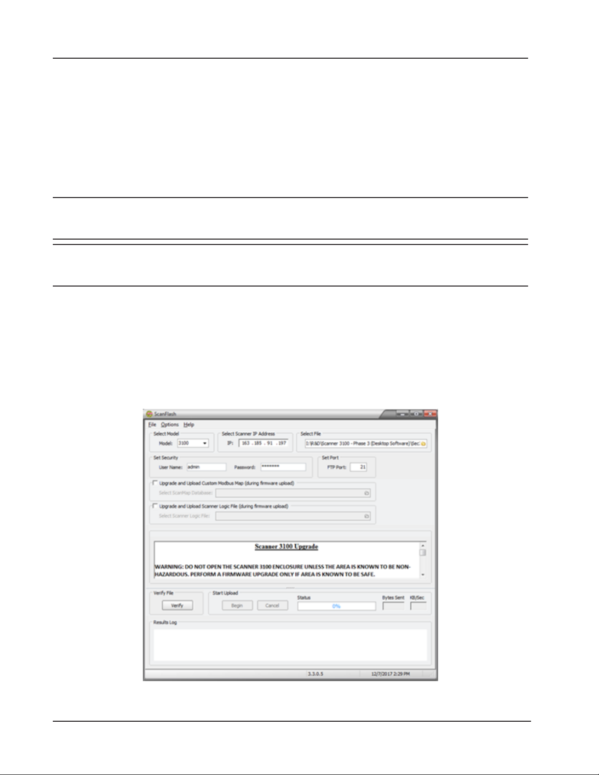
Appendix C Scanner 3100 EFM
• To upload a register map via the web interface, log into the Scanner 3100 interface, select ADMINISTRATION>
GENERAL from the taskbar and click Installed Files at the left of the screen. To erase the map currently installed,
click Uninstall PMAP File and click OK at the Conrm prompt. Then, click Browse under “Install Protocol Map
File,” select the desired conguration (.pmap) le to upload, and click Open. From the interface screen, click
Submit, click OK at the Conrm dialog, and wait for the le to upload.
• To upload a register map le via the ScanFlash utility, follow the upload instructions under ScanFlash Upload, page
C-2.
ScanFlash Upload
Important To download ScanFlash software, visit Cameron’s Measurement website at http://www.cameron.
slb.com/owcomputers, choose CAMERON Flow Computer Scanner 3100, and click the link for the
software install.
Important To upload rmware to the Scanner 3100, you must have Administrator-level user access. To upload
conguration les or custom Modbus register maps, you must have Conguration Editor-level or
Administrator-level user access.
1. Download ScanFlash from the Cameron website, as noted above.
2. Open a web browser and enter the IP address of the Scanner 3100 to establish a connection to the device.
3. Download all historical data from the Scanner 3100.
4. Open ScanFlash (shown in Figure C.1) and enter the IP address for the Scanner 3100.
5. Close the browser and clear the browser cache.
6. Select the rmware (BIN), conguration (SCF), Scanner Logic (SLBIN), or Modbus map (PMAP) le to be
uploaded.
Figure C.1—ScanFlash interface
C-2
Page 97

Scanner 3100 EFM Appendix C
7. Enter your user name and password for accessing the Scanner 3100 web interface. You must have the appropriate
user access level to proceed. See the “Important” note above.
8. Click Verify to conrm the connection and identify the current rmware version. The button will turn blue while the
utility attempts to communicate with the Scanner.
– When a connection has been veried, the Scanner’s system information will appear in the Results log at the
bottom of the screen.
– If a connection cannot be made, an error message will appear. Check the IP address, username and password
and click “Verify” again.
9. Click Begin to begin the le upload to the Scanner 3100.
10. Monitor the Status bar for percentage of upload completion. The process should take 3 to 4 minutes for rmware
les and less than a minute for conguration and Modbus map les.
When the rmware or conguration upload is completed, ScanFlash will automatically disconnect from the Scanner
3100. The Results log at the bottom of the screen will display “Successfully Flashed Scanner” and the utility will
try to reconnect to the device to retrieve the version information. The Results log will display the updated version
information if the new rmware is loaded and the reconnection is successful.
Note Verication may fail if the IP address has changed, as is typical with dynamic IP addresses. If the verication
fails, check the upper left corner of the device display, enter the IP address displayed on the device, click Verify
and conrm that the correct rmware is loaded. If desired, reset the device IP address after verication. For more
information, consult the Scanner 3100 Web Interface User Manual.
11. Open the web browser and login to the Scanner 3100 web interface.
12. Verify the date and time in the Scanner 3100 Device Status screen. If it is not correct, click on the Administration
tab and click Device Time to update the date and time.
Troubleshooting a Failed Upload
If the upload does not complete as expected, communications may have been lost during the upload or the le you are
attempting to upload (conguration or Modbus map) may have been created for use with a different version of rmware
than that installed on the Scanner 3100.
If there is no apparent rmware version conict, perform the following steps:
1. Click Cancel to abort the upload.
2. Remove power from the Scanner 3100.
3. Restore power to the Scanner 3100.
4. Restart ScanFlash and repeat the upload process.
C-3
Page 98

Appendix C Scanner 3100 EFM
This page intentionally left blank.
C-4
Page 99

WARRANTY - LIMITATION OF LIABILITY: Seller warrants only title to the products, software, supplies
and materials and that, except as to software, the same are free from defects in workmanship and
materials for a period of one (1) year from the date of delivery. Seller does not warranty that software
is free from error or that software will run in an uninterrupted fashion. Seller provides all software “as
is”. THERE ARE NO WARRANTIES, EXPRESS OR IMPLIED, OF MERCHANTABILITY, FITNESS
OR OTHERWISE WHICH EXTEND BEYOND THOSE STATED IN THE IMMEDIATELY PRECEDING SENTENCE. Seller’s liability and Buyer’s exclusive remedy in any case of action (whether in
contract, tort, breach of warranty or otherwise) arising out of the sale or use of any products, software,
supplies, or materials is expressly limited to the replacement of such products, software, supplies,
or materials on their return to Seller or, at Seller’s option, to the allowance to the customer of credit
for the cost of such items. In no event shall Seller be liable for special, incidental, indirect, punitive
or consequential damages. Seller does not warrant in any way products, software, supplies and
materials not manufactured by Seller, and such will be sold only with the warranties that are given by
the manufacturer thereof. Seller will pass only through to its purchaser of such items the warranty
granted to it by the manufacturer.
Page 100

 Loading...