

Page 1

NUFLO™
Scanner® 2000 microEFM
Hardware User Manual
Manual No. 9A-30165023, Rev. 10
Page 2

Important Safety Information
Symbols and Terms Used in this Manual
WARNING: This symbol identies information about practices or circumstances that can lead to per-
!
sonal injury or death, property damage, or economic loss.
CAUTION: Indicates actions or procedures which if not performed correctly may lead to personal
injury or incorrect function of the instrument or connected equipment.
Important: Indicates actions or procedures which may affect instrument operation or may lead to an
instrument response which is not planned.
Symbols Marked on Equipment
Attention! Refer to manual Protective (earth) ground
Technical Support Contact Information
Cameron
Measurement Systems Division
14450 John F. Kennedy Blvd.
Houston, TX 77032
Phone: 1-800-654-3760; 281-582-9500
Fax: 281-582-9599
NuFlo and ModWorX are trademarks of Cameron International Corporation (“Cameron”).
Scanner and Barton are registered trademarks of Cameron.
Modbus is a registered trademark of the Modbus Organization, Inc.
Flow-Cal is a registered trademark of Flow-Cal, Inc.
PGAS is a registered trademark of Quorum Business Solutions, Inc.
Foundation is a trademark of the Fieldbus Foundation.
Windows is a registered trademark of Microsoft Corporation.
Acrobat Reader is a registered trademark of Adobe Systems Incorporated.
© 2011 Cameron International Corporation (“Cameron”). All information contained in this publication is condential and proprietary property of Cameron. Any reproduction or use of these instructions, drawings, or
photographs without the express written permission of an ofcer of Cameron is forbidden.
All Rights Reserved.
Printed in the United States of America.
Manual No. 9A-30165023, Rev. 10
December 2011
Page 3

Scanner® 2000 microEFM Table of Contents
Contents
Important Safety Information ...............................................................................................................................ii
Section 1—Introduction ................................................................................................................................... 7
Flow Rate and Fluid Property Calculations ........................................................................................................ 8
Natural Gas .................................................................................................................................................. 8
Steam ........................................................................................................................................................... 8
Compensated Liquid .................................................................................................................................... 9
Uncompensated Liquid ............................................................................................................................... 9
Standard Features ............................................................................................................................................ 10
Product Identication ................................................................................................................................. 12
Hardware Options............................................................................................................................................. 12
Table 1.1—Scanner 2000 microEFM Specications .................................................................................. 15
Power Options .................................................................................................................................................. 21
Interface Software Functions ............................................................................................................................ 21
LCD/Keypad Functions..................................................................................................................................... 22
Viewing Real-Time Measurements ............................................................................................................ 23
Conguring Basic Parameters ................................................................................................................... 24
Viewing Daily and Hourly Logs .................................................................................................................. 24
Password-Protected Security ........................................................................................................................... 25
Section 2—Installing the Scanner 2000........................................................................................................ 27
Overview........................................................................................................................................................... 27
Hazardous Area Installations ............................................................................................................................ 27
Zone 1 (ATEX) Installations ....................................................................................................................... 27
Class I, Div. 1 (CSA) Installations .............................................................................................................. 28
Class I, Div. 2 (CSA) Installations .............................................................................................................. 29
Pressure Safety Precautions ............................................................................................................................ 29
Table 2.1—MVT Pressure Limits, Approvals and Bolt Specications ........................................................ 29
Mounting Options ............................................................................................................................................. 30
Pole-Mount Installation .............................................................................................................................. 30
Measuring Natural Gas via a Differential Pressure Meter ................................................................................ 33
Best Practices for Orice and Cone Meter Installation .............................................................................. 33
Installation Procedure—Direct Mount to Orice Meter or Cone Meter ....................................................... 34
Installation Procedure—Remote Mount to Orice Meter or Cone Meter ................................................... 35
Measuring Natural Gas via a Turbine Meter ..................................................................................................... 38
Best Practices ........................................................................................................................................... 38
Installation Procedure—Remote Mount to a Turbine Meter ....................................................................... 38
Installation Procedure—Direct Mount to a Turbine Meter (CSA Compliant) .............................................. 40
Measuring Steam via a Differential Pressure Meter ......................................................................................... 42
Best Practices ............................................................................................................................................ 42
Installation Procedure—Remote Mount to Orice Meter or Cone Meter ................................................... 43
Measuring Liquid via a Differential Pressure Meter .......................................................................................... 46
Best Practices ............................................................................................................................................ 46
Installation Procedure—Direct Mount to Orice Meter or Cone Meter ....................................................... 47
Installation Procedure—Remote Mount to Orice Meter or Cone Meter ................................................... 48
Measuring Compensated Liquid via a Turbine Meter ....................................................................................... 51
Best Practices ........................................................................................................................................... 51
Installation Procedure—Direct Mount to a Turbine Meter (CSA Compliant) .............................................. 51
Installation Procedure—Direct Mount to a Barton 7000 Series Turbine Meter (ATEX Compliant) ............ 52
Measuring Uncompensated Liquid via a Turbine Meter .................................................................................. 54
Best Practices ........................................................................................................................................... 54
Installation Procedure—Direct Mount to a Turbine Meter (CSA Compliant) .............................................. 54
iii
Page 4

Table of Contents Scanner® 2000 microEFM
Installation Procedure—Direct Mount to a Barton 7000 Series Turbine Meter (ATEX Compliant) ............ 55
Performing a Manifold Leak Test ...................................................................................................................... 55
Zero Offset (Static Pressure or Differential Pressure) ................................................................................ 56
Static Pressure Calibration and Verication ............................................................................................... 56
Differential Pressure Calibration and Verication ....................................................................................... 57
Placing the Scanner into Operation ........................................................................................................... 58
Industry Standard Compliance ......................................................................................................................... 58
Table 2.2—Industry Standards for Orice Meters ...................................................................................... 59
Industry Standards for Cone Meters .......................................................................................................... 59
Table 2.3—Industry Standards for Turbine Meters .................................................................................... 60
Table 2.4—Industry Standards for Fluid Properties ................................................................................... 60
Section 3—Wiring the Scanner 2000 ............................................................................................................ 61
Field Wiring Connections.................................................................................................................................. 61
Grounding Procedures .................................................................................................................................... 62
Power Supply Wiring ........................................................................................................................................ 63
Internal Power Supply ................................................................................................................................ 63
External Power Supply .............................................................................................................................. 64
Input Wiring ...................................................................................................................................................... 65
Turbine Flowmeter Input ............................................................................................................................ 65
RTD Input ................................................................................................................................................... 66
Output Wiring.................................................................................................................................................... 67
Digital Output (Pulse or Alarm) .................................................................................................................. 67
RS-485 Output—Permanent Computer Connection .................................................................................. 68
RS-485 Output—Laptop Computer Connection ........................................................................................ 69
Conguration via Keypad ................................................................................................................................. 70
Conguration via ModWorX™ Pro Software ................................................................................................... 70
Section 4—Conguration and Operation via Keypad ................................................................................. 71
Entering the Slave Address .............................................................................................................................. 72
Entering the Baud Rate .................................................................................................................................... 73
Editing the Date and Time ................................................................................................................................ 74
Editing the Contract Hour ................................................................................................................................. 75
Editing the Plate Size ....................................................................................................................................... 76
Section 5—Scanner 2000 Maintenance ........................................................................................................ 77
Lithium Battery Pack Replacement .................................................................................................................. 77
Circuit Assembly Replacement ......................................................................................................................... 78
Keypad Replacement ....................................................................................................................................... 81
MVT Replacement ............................................................................................................................................ 82
Section 6—Spare Parts .................................................................................................................................. 83
Table 6.1—Scanner 2000 microEFM Spare Parts ..................................................................................... 83
Table 6.2—Scanner 2000 microEFM Spare Parts (ATEX-Approved) ....................................................... 84
Table 6.3—RTD and Cable Assemblies (CSA-Approved) ......................................................................... 85
Table 6.4—Multi-Variable Transmitters ..................................................................................................... 85
Appendix A—Scanner 2000 Hardware Options ..........................................................................................A-1
Explosion-Proof Control Switch .......................................................................................................................A-1
RTD Assemblies ..............................................................................................................................................A-3
Weatherproof RTD Assembly (CSA, Class I, Div. 2) .................................................................................A-3
Explosion-Proof RTD Assembly (CSA, Class I, Div. 1) ............................................................................. A-3
Flameproof RTD Assembly (ATEX, Zone 1) .............................................................................................A-3
Communications Adapter (CSA Div. 1 or Div. 2, ATEX Zone 1).......................................................................A-4
Communications Adapter Installation
(for adapters purchased separately from a Scanner 2000) ......................................................................A-6
iv
Page 5

Scanner® 2000 microEFM Table of Contents
USB Communications Adapter (CSA Div. 1 or Div. 2) .....................................................................................A-6
Covering the Adapter ................................................................................................................................ A-6
Using the Adapter .....................................................................................................................................A-7
Adapter Kit Installation .............................................................................................................................. A-8
Input/Output Expansion Board (Not Available with Fieldbus) ..........................................................................A-8
Installation (for boards purchased separately from a Scanner 2000) ......................................................A-9
Wiring Diagrams .....................................................................................................................................A-10
Measurement Canada Seal Kit......................................................................................................................A-14
Seal Kit Installation .................................................................................................................................A-14
Terminal Housing ........................................................................................................................................... A-16
Appendix B—Lithium Battery Information ..................................................................................................B-1
Lithium Battery Disposal ................................................................................................................................. B-1
Transportation Information ..............................................................................................................................B-1
Material Safety Data Sheet..............................................................................................................................B-1
Appendix C—Scanner 2000 for Foundation™ Fieldbus ..............................................................................C-1
Overview..........................................................................................................................................................C-1
Hardware Options .....................................................................................................................................C-2
Specications ..................................................................................................................................................C-2
Table C.1—Scanner 2000 microEFM Specications (Fieldbus Devices Only) .........................................C-2
Installing the Scanner 2000 .............................................................................................................................C-3
Control System Components ....................................................................................................................C-3
Mounting Options ......................................................................................................................................C-4
Field Wiring Connections.................................................................................................................................C-4
Fieldbus Cable ..........................................................................................................................................C-5
Basic Wiring ..............................................................................................................................................C-5
Grounding Procedures .............................................................................................................................C-6
Lithium Battery Pack .................................................................................................................................C-7
Foundation™ Fieldbus Power Supply .......................................................................................................C-7
Terminal Housing Wiring Options ..............................................................................................................C-8
Device Conguration .......................................................................................................................................C-9
Fieldbus Conguration.....................................................................................................................................C-9
Device Description ..................................................................................................................................C-10
Block Descriptions ..................................................................................................................................C-10
Device Identication ................................................................................................................................C-11
Conguring Fieldbus Communications ...................................................................................................C-12
Fieldbus Operations ......................................................................................................................................C-15
Engineering Units ....................................................................................................................................C-15
Status ......................................................................................................................................................C-15
Fieldbus Troubleshooting ..............................................................................................................................C-15
General Errors ........................................................................................................................................C-15
Communication Faults ............................................................................................................................C-16
Maintenance ..................................................................................................................................................C-16
Board Replacement ................................................................................................................................C-17
Spare Parts .............................................................................................................................................C-22
Table C.2—Scanner 2000 microEFM Spare Parts .................................................................................C-22
Appendix D—Modbus® Communications Protocol ....................................................................................D-1
Introduction ......................................................................................................................................................D-1
Supported Commands.....................................................................................................................................D-1
Data Types ......................................................................................................................................................D-2
Security............................................................................................................................................................D-3
Registers .........................................................................................................................................................D-3
Product Code...................................................................................................................................................D-5
v
Page 6

Table of Contents Scanner® 2000 microEFM
Firmware Version/Register Table Version ........................................................................................................D-5
Manufacture Date/Sales Date .........................................................................................................................D-5
Analog Input 1 Calibration .......................................................................................................................D-16
Analog Input 2 Conguration ..................................................................................................................D-17
Analog Input 2 Calibration .......................................................................................................................D-17
Digital Input Conguration .......................................................................................................................D-18
Flow Rate Calculation Register .....................................................................................................................D-21
Fluid Property Register ..................................................................................................................................D-22
Tap Type Register ..........................................................................................................................................D-23
Output Conguration ...............................................................................................................................D-24
Pulse Input for Status Indication ...................................................................................................................D-25
Flow Calculation Parameter Registers (1-16)................................................................................................D-34
Base Units/Congured Units .........................................................................................................................D-34
Polling Registers............................................................................................................................................D-34
Interval/Daily/Event Pointer Registers ...........................................................................................................D-35
User-Dened Modbus® Registers Conguration ...........................................................................................D-43
Device Status ................................................................................................................................................D-45
Enron Log Data .............................................................................................................................................D-48
Appendix E—Fieldbus Communications Protocol .....................................................................................E-1
Device Properties ...........................................................................................................................................E-1
Parameter Tables ............................................................................................................................................E-1
Table E.1—Resource Block Parameters ...................................................................................................E-1
Table E.2—Transducer Block Parameters ................................................................................................E-3
Table E.3—Analog Input Block Parameters ..............................................................................................E-5
Table E.4—Transducer Error (XD_Error) and Block Alarm Codes ...........................................................E-7
Control Registers ............................................................................................................................................. E-7
Table E.5—Control Registers ....................................................................................................................E-7
Unit Conversion ...............................................................................................................................................E-8
Table E.6—Unit Conversions for XD Scale ...............................................................................................E-8
vi
Page 7

Scanner® 2000 microEFM Section 1
Section 1—Introduction
The NuFlo Scanner 2000 microEFM packs the gas, steam, and liquid measurement capabilities commonly
available only in large instruments into a compact, low-power ow computer. The device is available in a
CSA-approved explosion-proof and weatherproof model suitable for Class I, Div. 1 and Div. 2 (non-sparking)
installations, and an explosion-proof ATEX-approved model suitable for Zone 1 installations.
A single lithium battery pack typically powers the instrument for more than a year, making it ideal for remote
locations where power supply options are limited.
The Scanner 2000 is an economical chart recorder replacement, stand-alone totalizer, and ow computer, all
in one. It measures and computes standard volumes of gas, steam, petroleum liquids, and generic liquids with
a high degree of accuracy. These measurements are typically based on the differential pressure outputs of an
orice plate or a cone meter, or the linear pulse output of a turbine, positive displacement or vortex owmeter.
This combination is ideal for the gas and water measurement associated with coal bed methane operations.
Combining the differential pressure and static pressure inputs of an integral MVT with a process temperature
input, the Scanner 2000 offers everything needed for an AGA-3 or cone meter run in a compact, explosion-
proof device. Similarly, compensated liquid measurements can be obtained with an orice meter, cone meter,
or averaging pitot tube meter (such as Annubar
5167, cone, or averaging pitot tube calculation methods.
®
) installation, using ow calculations based on AGA-3, ISO-
Alternatively, the Scanner 2000 can be paired with a pulse output gas meter to obtain gas measurements in
compliance with AGA-7 standards. Live temperature and pressure inputs and the AGA-7 algorithm allow
computations based on gas turbine, rotary or vortex meters.
When liquid measurement is the goal and pressure inputs are not required, simply purchase the Scanner 2000
without the MVT and mount it directly to a liquid turbine meter, then install an RTD in the ow line for
temperature compensation. The Scanner 2000 uses algorithms based on AGA-7 principles to give accurate
measurement of API liquids and other generic liquids.
The addition of an optional expansion board expands the input/output capabilities to include a second turbine
meter input, enabling the Scanner 2000 to measure up to three separate ow runs, which could represent a
gas measurement, water measurement and oil measurement. A pulse input, two analog inputs, and an analog
output are also included on the expansion board.
Every Scanner 2000 microEFM is shipped complete with software for fully conguring hardware and ow
calculations, calibrating inputs, and collecting and viewing ow history. With hardware and software included
in the standard product offering, the Scanner 2000 microEFM is a complete alternative to the chart recorder.
Plus, because the Scanner can be powered by a lithium battery pack that is contained in the enclosure, the
installation cost for a Scanner 2000 is about the same as that for a chart recorder. High-speed communication
via industry standard Modbus
®
and Enron Modbus® protocols makes it easy to integrate the Scanner into other
measurement systems.
The Scanner 2000 is also available in a eldbus conguration that is powered by a eldbus network and
communicates via Foundation™ eldbus protocol. The eldbus conguration supports many of the hardware
options available for non-eldbus devices. See Appendix C—Scanner 2000 for Foundation™ Fieldbus, page
C-1, for details.
Measurement Canada has approved the Scanner 2000’s use for custody transfer applications when an optional
seal kit is installed. See Measurement Canada Seal Kit, page A-14, for details.
For a complete list of specications, see Table 1.1, page 14.
7
Page 8

Section 1 Scanner® 2000 microEFM
Flow Rate and Fluid Property Calculations
The Scanner 2000 calculates ow rates and uid properties for natural gas, steam and liquid ow. The
following descriptions identify the industry standards upon which these calculations are based.
Natural Gas
The Scanner 2000’s natural gas calculations and data storage conform to AGA-3, AGA-7, AGA-8, API 21.1,
and ISO-5167 industry standards. The ow calculations compensate for the effects of pressure, temperature,
and gas composition to calculate the volume of gas measured at specied base conditions. These calculations
typically require conguration of inputs including differential pressure, static pressure, process temperature,
and for AGA-7, a turbine meter input.
The integral multi-variable transmitter (MVT) is used to measure static pressure and differential pressure. A
4-wire, 100-ohm platinum RTD is recommended for measuring process temperature. Where temperature is
relatively constant, a xed temperature value may be congured.
Orice Plate (DP Input). The Scanner 2000 calculates natural gas ow rate from orice plates using
calculation methods found in the AGA-3 or ISO-5167 measurement standards. The natural gas uid
properties, such as density and compressibility, are calculated in accordance with AGA-8 (Detail and Gross
methods). Heating values are calculated in accordance with AGA Report 3, Part 3, Appendix F using the gas
properties dened in GPA 2145. Molar mass (molecular weight) calculations are also based on GPA 2145.
NuFlo Cone Meter (DP Input). The Scanner 2000 calculates natural gas ow rate from cone meters using
industry-recognized algorithms identied in the NuFlo Cone Meter User Manual. The natural gas uid
properties, such as density and compressibility, are calculated in accordance with AGA-8 (Detail and Gross
methods). Heating values are calculated in accordance with AGA Report 3, Part 3, Appendix F using the gas
properties dened in GPA 2145. Molar mass (molecular weight) calculations are also based on GPA 2145.
Gas Turbine Meter (Frequency Input). The Scanner 2000 calculates natural gas ow rate from a gas turbine
meter using calculations found in the AGA-7 measurement standard. The natural gas uid properties, such as
density and compressibility, are calculated in accordance with AGA-8 (Detail and Gross methods). Heating
values are calculated in accordance with AGA Report 3, Part 3, Appendix F using the gas properties dened in
GPA 2145. Molar mass (molecular weight) calculations are also based on GPA 2145.
Averaging Pitot Tube Meter (Annubar
averaging pitot tube meter using calculations found in the ASME MFC-12M-2006 measurement standard.
The natural gas uid properties, such as density and compressibility, are calculated in accordance with
AGA-8 (Detail and Gross methods). Heating values are calculated in accordance with AGA Report 3, Part 3,
Appendix F using the gas properties dened in GPA 2145. Molar mass (molecular weight) calculations are
also based on GPA 2145.
®
). The Scanner 2000 calculates natural gas ow rate from an
Steam
The Scanner 2000’s saturated steam calculations compensate for the effects of pressure, temperature, steam
properties, and steam quality.
Orice Plate (DP Input). The Scanner 2000 supports steam measurement based on AGA-3 or ISO-5167
ow rate methods for orice plates. Fluid properties are calculated in accordance with the IAPWS IndustrialFormulation 1997 (IF-97) standard. Temperature is calculated according to IF-97 for saturated steam, based
on static pressure. Therefore, an RTD is not required. The optional Chisholm and James wet correction
methods are supported for the measurement of vapor and uid.
8
Page 9

Scanner® 2000 microEFM Section 1
NuFlo Cone Meter (DP Input). The Scanner 2000 supports steam measurement using industry-recognized
algorithms identied in the NuFlo Cone Meter User Manual. Fluid properties for steam are calculated
in accordance with the IAPWS Industrial-Formulation 1997 (IF-97) standard. Temperature is calculated
according to IF-97 for saturated steam, based on static pressure. Therefore, an RTD is not required. The
optional Steven wet correction method is supported for the measurement of vapor and uid.
Averaging Pitot Tube Meter (Annubar
®
). The Scanner 2000 supports steam measurement based on ASME
MFC-12M -2006 ow rate methods for averaging pitot tube meters. Fluid properties are calculated in
accordance with the IAPWS Industrial-Formulation 1997 (IF-97) standard. Temperature is calculated
according to IF-97 for saturated steam, based on static pressure. Therefore, an RTD is not required. Wet
correction methods are not supported.
Compensated Liquid
The Scanner 2000 measures compensated petroleum liquid ow using an orice, cone, liquid turbine, or
averaging pitot tube (Annubar
for use with any of these owmeters.
• The “generic” uid properties calculation method is used to measure liquids such as water or emulsions,
based on user-supplied viscosity values and either user-supplied density values or user-supplied liquid
thermal expansion coefcients.
• The API-2540 calculation method provides temperature corrections for the following petroleum liquids:
crude oil, gasoline, jet fuel, fuel oils, and lube oil.
®
) owmeter. Users can select either of two uid property calculation methods
Orice Plate (DP Input). The Scanner 2000 calculates ow rates in accordance with AGA Report No. 3, Part
1 (1990) or ISO-5167 (2003) methods. When measuring liquids, the expansion factor (Y) is always equal to
1.0. Fluid property calculations for temperature-compensated measurements are based on API-2540 (1980),
Petroleum Measurement Tables.
NuFlo Cone Meter (DP Input). The Scanner 2000 calculates ow rates in accordance with industryrecognized algorithms identied in the NuFlo Cone Meter User Manual. When measuring liquids, the
expansion factor (Y) is always equal to 1.0. Fluid property calculations for temperature-compensated liquids
are based on API-2540 (1980), Petroleum Measurement Tables.
Liquid Turbine Meter (Frequency Input). The Scanner 2000 calculates ow rates in accordance with the
measurement principles upon which the AGA-7 standard is based. The user supplies a linear or multi-point
calibration factor, and the instrument performs the required compensation calculations, based on the RTD
input.
Averaging Pitot Tube Meter (Annubar
®
). The Scanner 2000 calculates ow rates in accordance with the
ASME MFC-12M-2006 measurement standard. When measuring liquids, the expansion factor (Y) is always
equal to 1.0. Fluid property calculations for temperature-compensated liquids are based on API-2540 (1980),
Petroleum Measurement Tables.
Uncompensated Liquid
The Scanner 2000 measures uncompensated liquid ow based on the input from a liquid turbine or PD meter.
Liquid Turbine Meter (Frequency Input) or PD Meter (Pulse Input). The Scanner 2000 calculates ow rate
from a liquid turbine meter via a frequency input, or from a contact closure (which requires the pulse input on
the optional expansion board). Flow rates and totals are calculated using a user-supplied linear or multi-point
calibration factor in accordance with API Manual of Petroleum Measurement Standards, Chapter 5, Section 3,
Measurement of Liquid Hydrocarbons by Turbine Meters (2005).
9
Page 10

Section 1 Scanner® 2000 microEFM
Standard Features
The standard Scanner 2000 microEFM features an explosion-proof enclosure with two conduit openings for
signal cable, a large LCD, a three-button keypad, integral multi-variable transmitter with integral vent plugs,
and a lithium double-D cell battery pack (Figure 1.1, page 10). MVTs are available in NACE and nonNACE models, and with bottom ports (gas measurement) and side ports (liquid and steam measurement).
Alternatively, Scanner 2000 congurations are available for direct connection to a turbine meter, which is
ideal for applications that do not require pressure measurement. The CSA-approved connection is shown in
Figure 1.2, page 11; the ATEX-approved connection is shown in Figure 1.3, page 11.
The main circuit board offers a turbine input, two communications ports, an RTD input, and a digital output.
See Section 2—Installing the Scanner 2000, for wiring diagrams.
Ground screw
LCD / keypad
Multi-variable transmitter
High pressure/low pressure
port indicator
Figure 1.1—Scanner 2000 microEFM with integral MVT; MVTs are available with bottom ports (shown) or side
ports
Conduit plug
Enclosure lid
(remove to access keypad)
Mount for pole-mount hardware
MVT adapter
(NACE-compliant MVT available)
Integral vent plugs
10
Page 11

Scanner® 2000 microEFM Section 1
Ground screw
LCD / keypad
LCD / keypad
Conduit plug
Enclosure lid
(remove to access keypad)
Mount for pole-mount hardware
CSA-approved
3/4 in. to 1 in. adapter
CSA-approved
union (connects directly
to the turbine meter)
Figure 1.2—Scanner 2000 microEFM for direct connection to a turbine meter (CSA-approved)
Figure 1.3—Scanner 2000 microEFM for direct connection to a Barton 7000 Series turbine meter (ATEXapproved)
11
Page 12

Section 1 Scanner® 2000 microEFM
Product Identication
Each device is labeled with a serial tag that identies the product by model number and serial number
and identies the maximum operating pressure, working pressure, and differential pressure of the integral
MVT (Figure 1.4). The tag content depicted in Figure 1.4 shows the electrical protection afforded by SIRA
certication. CSA-approved products are marked accordingly with the respective ratings and symbols.
Units approved for custody transfer by Measurement Canada will have an additional label attached, bearing
the MC approval number. See Measurement Canada Seal Kit, page A-14 for details.
CE marking and number of notified
body responsible for production
Explosion-proof marking
Equipment Group II, Category 2 (hazardous conditions
are likely to occur in normal operation occasionally (>10<1000 hours/year)
Explosive Atmosphere: Gas, Dust
Flameproof for explosive gas environments other than
mines; temperature class
Temperature tested for dust and suitable for use in
Zone 21 area; ingress protection: dust-tight and protected
against the effects of continuous immersion in water;
maximum surface temperature: 85°C
Certification number
Figure 1.4—Device serial tag
Hardware Options
The following hardware options are available for customizing the Scanner 2000 to a user’s specic needs.
Input/Output Expansion Board
An expansion board (Part No. 9A-30188004) allows the instrument to support a differential pressure meter
run and two turbine meter runs simultaneously. The board features a turbine input, a pulse input, two analog
inputs, an analog output, and 256 KB of memory. See Input/Output Expansion Board (Not Available with
Fieldbus) for wiring diagrams.
Standard Device
(Main Board Only)
Integral MVT Integral MVT
2 RS-485 communication ports 2 RS-485 communication ports
1 process temperature input 1 process temperature input
1 turbine meter input 2 turbine meter inputs
— 1 congurable pulse input
— 2 congurable analog inputs (1-5V)
1 congurable digital output 1 congurable digital output
— 1 congurable analog output (4-20 mA)
(Main Board and Expansion Board)
Expanded Device
Important The Scanner 2000 for
option.
12
Foundation™ Fieldbus does not support the I/O expansion board
Page 13

Scanner® 2000 microEFM Section 1
Control Switch
During normal operation, the LCD displays the selected parameters in a continuous scroll. The control switch
allows the user to manually control the display of parameters on the LCD and view daily logs instantaneously
without removing the instrument cover. The control switch is available in two models:
• CSA-approved model for use in Div. 1 and Div. 2 installations (Part No. 9A-30054001)
• ATEX-approved model (Part No. 9A-30054002)
See Explosion-Proof Control Switch, page A-1 for details.
RTD
The temperature input for Scanner 2000 ow calculations is typically supplied by an RTD. Cameron offers
three different types of RTDs to cover both explosionproof and weatherproof applications.
See RTD Assemblies, page A-3, for details. See Table 6.3 for part numbers.
External Explosion-Proof RS-485 Communications Adapter
The explosion-proof communications adapter provides a quick-connect option for communicating with the
Scanner 2000 (downloading logs, for example) via laptop or PC without removing the instrument cover.
Optional accessories include an RS-232 to RS-485 converter. See Communications Adapter (CSA Div. 1 or
Div. 2, ATEX Zone 1), page A-4, for details.
The communications adapter is available in two models:
• CSA-approved model (Part No. 9A-90017004) for use with Div. 1 or Div. 2 installations or with
tion™ eldbus congurations
• ATEX-approved model (Part No. 9A-90017008) for use with Zone 1 installations
Founda-
External Explosion-Proof USB Communications Adapter
The CSA-approved USB communications adapter allows the connection of a Scanner 2000 directly to a
USB port of a laptop or PC. A user-supplied universal USB cable is required. The adapter is factory-installed
when purchased with a Scanner 2000. It is also available as a kit with an installation CD for upgrading
communications in a eld unit. See USB Communications Adapter (CSA Div. 1 or Div. 2), page A-6 for
details.
• COM adapter (replacement part, no installation CD): Part No. 2295524-01
• COM adapter kit with installation CD (required for adding a USB connector to an existing Scanner 2000):
Part No. 2295634-01
Pole-Mounting Kit
A hardware kit (Part No. 9A-30028004) consists of a mounting bracket, two U-bolts and nuts allows the
Scanner 2000 to be mounted on a 2-in. pole. The mounting bracket also provides the extension necessary to
keep the instrument in a vertical position when it is bulkhead-mounted to a at, vertical surface. See Pole-
Mount Installation, page 30, for details.
Accessory Packages for Communication and Power
The NuFlo Scanner 1000 Series Communication and Accessory Packages provide wireless communications
or telephone interface communication devices and the sub-systems to power them. Power can also be
provided for control equipment such as solenoids and high-capacity relays. These packages are CSA-certied
for Class I, Division 2 and NEMA 4 or 4X locations.
13
Page 14

Section 1 Scanner® 2000 microEFM
The NuFlo Solar Power and Communications Unit (Part No. 9A-1000-1086T) continuously powers the
Scanner 2000 and provides short haul (250m) WIFI communication to a user’s PC. A user can download
conguration settings or ow data without entering the hazardous location or leaving his vehicle. This
CEC-certied package is approved for Division 2 installations and is wired to the Scanner via RS-485 (two
conductors) and power (two conductors). It comes with a 12V 12-Ahr battery, a voltage regulator and all the
necessary communication gear wired within a weatherproof enclosure. This package is designed for use with
a 10-watt user-supplied solar panel (not included, but also available from Cameron). Contact the factory for
details.
The NuFlo Solar Power package (Part No. 9A-1000-1085T) continuously powers the Scanner 2000. This
CEC-certied assembly is approved for Division 2 installations and is wired to the Scanner with two
conductors. It comes with a 12V 7-Ahr battery and a charge controller wired within a weatherproof enclosure.
This package is designed for use with a 5-watt user-supplied solar panel (not included, but also available from
Cameron). Contact the factory for details.
Measurement Canada Seal Kit
Scanner 2000 devices approved by Measurement Canada for custody transfer applications must be installed
according to Measurement Canada regulations. Those regulations require the installation of a jumper and a
device seal to prevent changes to the conguration of a device after the unit has been congured and the seal
has been applied. An optional seal kit (Part No. 2295583-01) supplied by Cameron contains a jumper, a lead
seal assembly, an Allen wrench and a label for properly marking a device. See Measurement Canada Seal Kit,
page A-14, for kit installation instructions.
Terminal Housing/Junction Box
Cameron’s Model TH4 terminal housing expands the number of devices or I/O connections that can be added
to a Scanner 2000. The terminal housing is approved by CSA for use with the Scanner 2000. When installed
with a Scanner 2000, the assembly is rated for Class I, Div. 1, Groups C and D and Class I, Div. 2, Groups
A, B, C, and D. If the Scanner is supplied without the terminal housing, it is approved for installation in
Group B areas as well as Group C and D areas. See Terminal Housing, page A-16, for a diagram of a typical
installation.
Foundation™ Fieldbus Communications
Foundation™ eldbus communications are now available for the Scanner 2000 and must be specied at the
time of order. Each eldbus unit is designed with an expansion board that allows Modbus signals from the
Scanner 2000 to be converted to eldbus prior to the distribution of eldbus data to devices on a eldbus
network. See Appendix C—Scanner 2000 for Foundation™ Fieldbus for installation details.
Fieldbus communications are also available in an ATEX-approved intrinsically safe Scanner 2000. See
Cameron manual Scanner 2000 for
Foundation™ Fieldbus, Part No. 9A-30165035, for details.
14
Page 15

Scanner® 2000 microEFM Section 1
Table 1.1—Scanner 2000 microEFM Specications
Electrical Safety
Classication
(Standard Scanner 2000
and Scanner 2000 with
Expansion Board)
Approved by CSA for US and Canada
Class I, Div. 1, Groups B, C, D (explosion-proof)
Class I, Div. 2, Groups A,B,C,D (non-sparking)
Type 4 enclosure, ANSI 12.27.01 single seal (0 to 3000 psi)
T6 temperature class
Approved by SIRA to
ATEX 07ATEX 1037X
IECEx SIR07.0022X
E
II 2 GD
c
Ex d IIC T6 (-40°C to +70°C) or Ex tD A21 IP68 T85°C (-40°C to +70°C)
GOST-R and GOST-K certied
Electrical Safety
Classication
(Scanner 2000 for
Foundation™ Fieldbus)
Pressure Classication ASME pressure vessel code compliant, 0 to 3000 psi
Measurement Agency
Approvals
Enclosure Cast aluminum, painted with epoxy and polyurethane
Weight 11.2 lb (5.08 kg), approximate
System Power Internal power supply
Operating Temperature -40°C to 70°C (-40°F to 158°F)
LCD Display 8-digit top readout of values (7-segment characters)
Keypad 3-key membrane switch
Approved by CSA for US and Canada
Class I, Div. 1, Groups B, C, D (explosion-proof)
Type 4 enclosure, ANSI 12.27.01 single seal (0 to 3000 psi)
T6 temperature class
(CRN 0F10472.5C)
Approved by Measurement Canada for custody transfer, 0 to 1500 psi
(Approval No. AG-0557C)
Battery pack, 2 “D” batteries in series, 7.2V, lithium
Battery life, 1-year, typical
External power supply (6 to 30 VDC) with internal battery backup (reverse
polarity protected)
LCD contrast is reduced below -30°C (-22°F)
6-digit bottom readout of scrolling parameters and associated engineering
units (11-segment characters for easy-to-read prompts)
View up to 12 user-dened parameters
View daily log data
User-selectable units of measurement
0.3” character height
Congurable scan parameters and duration
Adjustable contrast and update period
Password-protected security available
15
Page 16

Section 1 Scanner® 2000 microEFM
Table 1.1—Scanner 2000 microEFM Specications
Logging Daily records: 768 (>2 years)
Interval records:
• Adjustable from 5 sec to 12 hours
• 2304 (>3 months of 1-hour intervals) with main board
• 6392 (>8 months of 1-hour intervals) with main board and expansion
board
Event/alarm records: 1152
Records up to 16 user-dened parameters
Logs stored in non-volatile memory for up to 10 years
Memory Non-volatile memory for conguration and log data
256 KB standard
512 KB standard plus expansion board
Communications/
Archive Retrieval
RTU Modbus
• two on-board RS-485 communications ports (300 to 38.4K baud)
• full download from main board in approximately 3 minutes (approx. 6
minutes with expansion board)
Enron Modbus® compliant downloads
User-deneable Modbus® map with up to 25 oating point values
Explosion-proof control switch option
• Alternative to keypad controls (allows navigation of LCD views without
removing the enclosure lid)
• View next LCD display parameter
• View up to 99 daily logs on LCD
Explosion-proof communications adapter option
• External connector allows quick-connect to RS-485 COM ports without
removing the enclosure lid
• USB or RS-485 COM adapter installs in conduit opening
Flow Rate Calculations Natural Gas (Orice/NuFlo Cone):
AGA Report No. 3: Orice Metering of Natural Gas and Other Related
Hydrocarbon Fluids;
ISO 5167: Measurement of Fluid Flow by Means of Pressure Differential
Devices Inserted in Circular Cross-Section Conduits Running Full
NuFlo Cone Meter User Manual, www.c-a-m.com (Measurement Systems
Division page)
Natural Gas (Turbine Meter):
AGA Report No. 7: Measurement of Natural Gas by Turbine Meters
Natural Gas (Averaging Pitot Tube Meter):
ASME MFC-12M-2006: Measurement of Fluid Flow in Closed Conduits
Using Multiport Averaging Pitot Primary Elements
Steam (Orice/NuFlo Cone):
AGA Report No. 3: Orice Metering of Natural Gas and Other Related
Hydrocarbon Fluids;
ISO 5167: Measurement of Fluid Flow by Means of Pressure Differential
Devices Inserted in Circular Cross-Section Conduits Running Full
NuFlo Cone Meter User Manual, www.c-a-m.com (Measurement Systems)
Liquids (Turbine):
API Manual of Petroleum Measurement Standards, Chapter 5, Section 3,
Measurement of Liquid Hydrocarbons by Turbine Meters
®
16
Page 17

Scanner® 2000 microEFM Section 1
Table 1.1—Scanner 2000 microEFM Specications
Flow Rate Calculations
(cont’d)
Fluid Property
Calculations
MVT Provides linearized static pressure and differential pressure
Compensated Liquids (Orice/NuFlo Cone/Turbine):
AGA Report No. 3: Orice Metering of Natural Gas and Other Related
Hydrocarbon Fluids;
ISO 5167: Measurement of Fluid Flow by Means of Pressure Differential
Devices Inserted in Circular Cross-Section Conduits Running Full
NuFlo Cone Meter User Manual, www.c-a-m.com (Measurement Systems)
AGA Report No. 7: Measurement of Natural Gas by Turbine Meters (as
basis for liquid measurement)
Natural Gas:
AGA Report No. 8; “Compressibility Factors of Natural Gas and Other
Related Hydrocarbon Gases”; Second Edition, AGA Catalogue XQ9212;
American Gas Association, Arlington Virginia 1994.
AGA Report No. 3, “Orice Metering of Natural Gas and Other
Hydrocarbon Fluids,” Part 3, “Natural Gas Applications,” Third Edition,
1992, Appendix F, Heating Value Calculation.”
GPA 2145-09, “Table of Physical Properties for Hydrocarbons and Other
Compounds of Interest to the Natural Gas Industry,” Gas Processors
Association, Tulsa Oklahoma, 2008.
Steam:
IAPWS Industrial-Formulation 1997 (IF-97)
Wet Correction Methods: James and Chisholm (Orice); Steven (NuFlo Cone)
Liquids:
Generic (based on user-dened constants for density and viscosity)
API-2540 - 1980, Petroleum Measurement Tables
Available with bottom ports or side ports
NACE-compliant units also available (See Table 2.1—MVT Pressure Limits,
Approvals and Bolt Specications, page 29 for bolt specications.)
Process temperature: -40°C to 121°C (-40°F to 250°F)
User-adjustable sample time and damping
Stability: Long-term drift is less than ±0.05% of upper range limit (URL) per
year over a 5-year period
Differential Pressure Accuracy (30 In. H2O)
• ±0.10% for spans ≥10% of the sensor URL
• ±(0.010) (URL÷SPAN) for spans <10% of the sensor URL
• ±0.30% of full scale over full operating temperature range
Differential Pressure Accuracy (200 to 840 In. H2O)
• ±0.05% for spans ≥10% of the sensor URL
• ±(0.005) (URL÷SPAN) for spans <10% of the sensor URL
• ±0.25% of full scale over full operating temperature range
Static Pressure Accuracy (500 psia)
• ±0.05% for spans ≥5% of the sensor URL
• ±(0.0025) (URL÷SPAN) for spans <5% of the sensor URL
• ±0.25% of full scale over full operating temperature range
Static Pressure Accuracy (300, 1500, 3000 and 5300 psia)
• ±0.05% for spans ≥10% of the sensor URL
• ±(0.0025) (URL÷SPAN) for spans <10% of the sensor URL Temperature
Performance
• ±0.25% of full scale over full operating temperature range
17
Page 18

Section 1 Scanner® 2000 microEFM
Table 1.1—Scanner 2000 microEFM Specications
MVT Accuracy Effect on differential pressure for a 100-psi change in static pressure:
Max.
SP/SWP
(PSIA)
100 30 150 ±0.05% of URL ±0.01% of reading
300 200 450 ±0.007% of URL ±0.01% of reading
500 200 750 ±0.010% of URL ±0.01% of reading
1500 200 2250 ±0.010% of URL ±0.01% of reading
3000* 200 4500 ±0.010% of URL ±0.01% of reading
5300* 200 7420 ±0.010% of URL ±0.01% of reading
DP
(IN H2O)
Overrange
(PSIA) Zero Shift Span Shift
840 ±0.002% of URL ±0.01% of reading
300 ±0.004% of URL ±0.01% of reading
400 ±0.004% of URL ±0.01% of reading
840 ±0.004% of URL ±0.01% of reading
300 ±0.004% of URL ±0.01% of reading
400 ±0.004% of URL ±0.01% of reading
840 ±0.004% of URL ±0.01% of reading
300 ±0.004% of URL ±0.01% of reading
400 ±0.004% of URL ±0.01% of reading
840 ±0.004% of URL ±0.01% of reading
* 3000-psia and 5000-psia ranges have not been evaluated by Measurement Canada
Inputs (Main Board) Process Temperature Input
• 100-ohm platinum RTD with 2-wire, 3-wire, or 4-wire interface
• Sensing Range: -40°C to 427°C (-40°F to 800°F)
• Accuracy: 0.2°C (0.36°F) over sensing range at calibrated temperature
• Temperature effect: 0.3°C over operating range of -40°C to 70°C (0.54°F
over operating range of -40°F to 158°F)
• Resolution: 24 bits
• User-adjustable sample time and damping
Turbine Meter Input 1
• Congurable sensitivity adjustment (20, 50, 100 or 200 mV, peak-to-peak)
• Frequency range: 0 to 3500 Hz
• Input amplitude: 20 mV to 3000 mV, peak to peak
Turbine Setting Input Sensitivity
0 – 1000 Hz 1000 – 2000 Hz 2000 – 3500 Hz
Low (20mV) 20 mVpp 25 mVpp 50 mVpp
Med (50mV) 50 mVpp 70 mVpp 110 mVpp
High (100mV) 100 mVpp 150 mVpp 250 mVpp
Max (200mV) 200 mVpp 380 mVpp 620 mVpp
18
Page 19

Scanner® 2000 microEFM Section 1
Table 1.1—Scanner 2000 microEFM Specications
Inputs (Expansion Board);
not applicable to
Foundation™ eldbus
congurations
Analog Input (2)
• 3-wire sensor interface
• 1-5V or 4-20 mA
• Sensor power same as external power supply for main board (6 to 30
VDC)
• Accuracy: 0.1% of full scale
• Temperature effect: 0.25% of full scale over operating temperature
range of -40°C to 70°C (-40°F to 158°F)
• Resolution: 20 bits
• User-adjustable sample time and damping
Pulse Input
• Accepts a signal from turbine meter or positive displacement meter
• Optically isolated
• Input: 3 to 30 VDC or contact closure
• Cannot be used as a frequency input simultaneously with Turbine Meter
Input 2
• Can be used as a status input when Turbine Meter Input 2 is in use
Turbine Meter Input 2
• Congurable sensitivity adjustment (20, 50, 100 or 200 mV, peak-topeak)
• Frequency range: 0 to 3500 Hz
• Input amplitude: 20 mV to 3000 mV, peak to peak
• Cannot be used simultaneously with pulse (frequency) input
Turbine Setting Input Sensitivity
0 – 1000 Hz 1000 – 2000 Hz 2000 – 3500 Hz
Low (20mV) 20 mVpp 25 mVpp 50 mVpp
Med (50mV) 50 mVpp 70 mVpp 110 mVpp
High (100mV) 100 mVpp 150 mVpp 250 mVpp
Max (200mV) 200 mVpp 380 mVpp 620 mVpp
Output (Main Board) Digital Output
• Congurable as pulse output or alarm output
• Solid-state relay
• Output rating: 60 mA max @ 30 VDC
When congured as pulse output:
• Maximum frequency: 50 Hz
• Congurable pulse duration (65,535 msec max)
• Congurable pulse representation (1 pulse = 1 MCF)
• Based on any accumulator (ow run or turbine meter run)
When congured as alarm output:
• Low/high
• Out-of-range
• Status/diagnostic
• Latched/unlatched
• Normally open/normally closed
19
Page 20

Section 1 Scanner® 2000 microEFM
Table 1.1—Scanner 2000 microEFM Specications
Output (Expansion Board)
not applicable to
Foundation™ eldbus
congurations
Interface Software Provided at no charge
System Requirements Operating System - Windows XP or later
Analog Output
• 4-20 mA
• Accuracy: 0.1% of full scale @ 25°C (77°F), 50 PPM/°C (27.8 PPM/°F)
temperature drift
• Represents any measured variable (e.g., differential pressure) or
calculated parameter (e.g., ow rate)
• Optically isolated
• Resolution: 16 bits
Easy to use
Real-time data polling
Complete conguration
Conguration upload for conguring multiple units
Multi-level security
Field calibration
• 1 to 12 calibration points for each parameter
• Three methods: multi-point, set zero point, and verify (API compliant)
• Inputs are automatically locked during calibration
Maintenance
• Change plate
• Change cone (linearization: 1 to 12 points)
• Change gas composition
• Change steam properties
• Change ow coefcients
• Change K-factor (linearization: 1 to 12 points)
• Change turbine owmeter
• Change generic/API liquid parameters
Archive data downloads
• Congurable downloads of “all” or “new” records
• Download types: daily, interval, and event/alarm records
• Downloads are automatically saved in uneditable binary (SDF) les
• Exports to .xls, .csv, .rtf, .html, Flow-Cal
®
and PGAS® formats
Reporting
• Daily logs (table or trend graph)
• Interval logs (table or trend graph)
• Event/alarm logs
• Conguration settings
• Calibration settings
• Snapshot of current status data and calculated parameters
Computer/Processor - 1 GHz or faster Pentium-compatible CPU
Memory - 128 MB of RAM
Hard Disk Space - 100 MB for program les, 30 MB for Adobe Reader,
adequate space for data les
Drive - CD-ROM for install
Display - 1024 x 600, 16-bit color display or greater
Browser - Internet Explorer 7 or later
Internet Connection - for web links, tech support
Communications Port - physical or virtual RS-232 compatible serial port
20
Page 21

Scanner® 2000 microEFM Section 1
Power Options
The standard Scanner 2000 microEFM can be powered two ways:
• with the internal lithium battery pack supplied with each Scanner 2000 (shown in Figure 1.5)
• with an external customer-supplied power supply (6 to 30 VDC); the lithium battery provides backup
power when an external power supply is used
Wiring diagrams are provided in Section 3—Wiring the Scanner 2000.
Foundation™ eldbus models are powered by a customer-supplied eldbus power supply. In the event that
eldbus power is lost, the lithium battery will help ensure that timekeeping and volume accumulation will not
be interrupted. See Appendix C—Scanner 2000 for Foundation™ Fieldbus for details.
Lithium battery pack
(double D cell), secured
by a velcro strap
Main circuit board
Battery connector
Figure 1.5— Scanner 2000 microEFM, internal view
Interface Software Functions
The ModWorX™ Pro interface software is designed for simplicity and ease of use. Its intuitive, wellorganized screens allow users to calibrate and congure the Scanner 2000 microEFM within just a few
minutes, and download log archives in an easy-to-read report. RTU Modbus® protocol and RS-485
communications ensure easy access to logs. Up to 16 user-selectable parameters can be logged and
downloaded using ModWorX™ Pro software.
The software interface is designed around the most common needs of the eld operator. A read-only Main
screen (Figure 1.6) provides a quick reference to real-time totals and ow rates, input data, and system data. It
is also home to four task-based menus: Calibrate, Maintain Flow Run, Maintain Turbine, or Congure, and a
large red “Download” button for downloading archive data.
21
Page 22

Section 1 Scanner® 2000 microEFM
Figure 1.6—ModWorX™ Pro software interface
The standard Scanner 2000 microEFM saves up to 2304 interval logs (interval periods are adjustable from
5 sec to 12 hours ), 768 daily logs, and 1152 event/alarm logs in nonvolatile memory. With the optional
expansion board, the Scanner 2000 saves up to 6392 interval logs. A user can selectively download data logs
and instrument conguration settings using the ModWorX™ Pro software. The download les are stored in
an uneditable format on the user’s CPU, and can be viewed immediately or exported to an alternative format
(.csv, .xls, .rtf, html, Flow-Cal®, or PGAS®).
Log data can be viewed or printed as a table or a trend chart, or exported to a spreadsheet.
Event logs track user changes to ow parameters that impact log data. Such changes may include orice plate
changes, K-factor changes, input setting changes, and device events like over-range and resets. Event/alarm
logs can be viewed or printed in tabular format. In addition to showing old and new values, each event log is
time-stamped, and includes the register associated with the change.
Instructions for installing the software are provided on the installation CD pocket folder provided with each
instrument. User manuals containing step-by-step instructions on software functions are linked to the software
interface for quick and easy access (note the tabbed links at the bottom of the screen in Figure 1.6).
LCD/Keypad Functions
From the three-button keypad on the front of the instrument, the user can perform the following tasks:
• scroll through display parameters
• view daily ow totals
• save a current total
• check the temperature and system voltage
• congure basic parameters such as slave address, baud rate, time, turbine K-factor, and orice plate size
22
Page 23

Scanner® 2000 microEFM Section 1
Section 4—Conguration and Operation via Keypad, guides users step by step through the conguration
of these parameters using the keypad. Figure 1.7 summarizes the functions that can be accessed with each
button.
CONFIGURATION:
Move between menus
and menu selections
OPERATION:
View next parameter
TEST ACCESS
CONFIGURATION:
CONFIGURATION:
Save configuration
settings
OPERATION:
Save totals
Change digits and
other menu selections
PRESS +
simultaneously to view
time/date, temperature,
OPERATION:
View daily logs
PRESS +
simultaneously to access
Configuration menu
and battery voltage
Figure 1.7—Keypad functions
Important All operating parameters can be congured using the ModWorX™ Pro software provided
with the Scanner 2000. See Section 3—Wiring the Scanner 2000 for instructions on connecting your laptop or PC to the instrument.
Viewing Real-Time Measurements
Up to 12 parameters can be congured for display on the LCD using ModWorX™ Pro software. During
normal operation, the LCD displays the selected parameters in a continuous scroll.
A user can stop the scrolling action and manually advance the parameter displayed on the screen by removing
the cover of the instrument and pressing the LEFT ARROW button on the keypad (Figure 1.7, page 23). The
parameter selected for display will appear as shown in Figure 1.8.
23
Page 24

Section 1 Scanner® 2000 microEFM
Parameter changes
when LEFT ARROW
button is pressed
Figure 1.8—LCD display of real-time measurements
Note If the instrument is equipped with an explosion-proof switch, the user can manually control the pa-
rameter displayed without removing the instrument cover. See Appendix A—Scanner 2000 Hardware
Options for more information.
Conguring Basic Parameters
Pressing the UP ARROW and ENTER buttons simultaneously allows the user to enter the conguration mode
(Figure 1.9).
Figure 1.9—In conguration mode, the parameter to be congured is displayed at the bottom of the LCD and
the setting for that parameter is displayed in the top LCD.
In that mode, the user can congure the following parameters without the use of a laptop computer:
• slave address
• baud rate
• date and time
• contract hour
• orice plate size
Step-by-step instructions are provided in Section 4—Conguration and Operation via Keypad. All other
instrument conguration is performed via the ModWorX™ Pro software interface.
Viewing Daily and Hourly Logs
Up to 99 consecutive daily logs can be viewed using the keypad.
Pressing the Log button changes the LCD display mode from normal operation (scrolling) to a daily log view
mode (Figure 1.10). The two-digit ashing number or “log index” on the left side of the LCD represents the
number of days that have passed since the log was saved. The user can increment or decrement the number by
clicking the UP ARROW or DOWN ARROW buttons. For example, “01” will display the last daily log saved.
An index of “05” will display the daily log saved 5 days ago.
By default, the top display shows ow volume, however the user can congure the display to show any of
the 16 parameters available using ModWorX™ Pro software. The bottom display shows the date. The entire
24
Page 25

Scanner® 2000 microEFM Section 1
log archive—up to 768 daily logs, 2304 adjustable interval logs, and 1152 event/alarm logs— can be viewed
using ModWorX™ Pro software.
Volume
(or other assigned
parameter)
Log index
(Days since log
was created)
Date stamp
(MMDDYY)
Figure 1.10—LCD display of daily logs
Password-Protected Security
A keypad security access code prevents unauthorized personnel from altering the calibration or accumulated
volume data in the instrument. The security feature may be disabled if this protection is not required.
Password-protected security access is enabled using the ModWorX™ Pro software. When this feature is
enabled, the user will be prompted for a four-digit password each time he attempts to enter a menu from the
keypad (Figure 1.11). The ModWorX™ Pro software is required for establishing or changing the password.
Figure 1.11—LCD display of security password menu
25
Page 26

Section 1 Scanner® 2000 microEFM
26
Page 27

Scanner® 2000 microEFM Section 2
Section 2—Installing the Scanner 2000
Overview
The Scanner 2000 microEFM is fully assembled at the time of shipment and ready for mounting. However,
Cameron recommends that operators congure the microEFM prior to mounting if the instrument is to be
installed in a hazardous area. The enclosure must be opened to congure the device, either via keypad controls
or via software, and once the instrument is mounted in a hazardous area, the cover should not be removed
unless the area is void of combustible gas and vapors.
Hazardous Area Installations
The Scanner 2000 is ATEX-certied (Zone 1) and CSA-certied (Div. 1 and Div. 2) for hazardous area
use. Installation requirements vary, depending on the certication required. Carefully review the following
hazardous area requirements before installing a Scanner 2000 in a hazardous area.
Zone 1 (ATEX) Installations
The ATEX-certied standard Scanner 2000 microEFM and the ATEX-certied Scanner 2000 microEFM with
expansion board are fully compliant with European ATEX Directive 94/9/EC, Annex II,1.0.6.
The following instructions apply to equipment covered by certicate number 07ATEX 1037X:
• The instrument may be located where ammable gases and vapours of groups IIA, lIB and IIC may be present.
• It is only certied for use in ambient temperatures in the range
-40°C to +70°C and should not be used outside this range.
• It has not been assessed as a safety-related device (as referred to
by Directive 94/9/EC Annex II, clause 1.5).
• Installation shall be carried out by suitably trained personnel in
accordance with the applicable code of practice (EN 60079-14
within Europe).
• Repair of this equipment shall be carried out by the manufacturer
or in accordance with the applicable code of practice (IEC 60079-
19).
• If the instrument is likely to come into contact with aggressive
substances, the user is responsible for taking suitable precautions
to prevent it from being adversely affected, thus ensuring that the
type of protection is not compromised.
– Aggressive substances may include, but are not limited to, acidic liquids or gases that may attack met-
als, or solvents that may affect polymeric materials.
– Suitable precautions may include, but are not limited to, regular checks as part of routine inspections
or establishing from the material’s data sheet that it is resistant to specic chemicals.
27
Page 28

Section 2 Scanner® 2000 microEFM
Wiring Precautions
CAUTION In accordance with EN60079-0, Clause 16.5, all cable and cable glands must be rated for
80ºC. The Scanner 2000 may be tted as a remote unit when all the cable entries are tted with ameproof glands that have been suitably certied by a notied body.
CAUTION When a stand off tube is used to connect a turbine meter to an ATEX-approved Scanner
2000, it shall be used only with the turbine meter pick off coil bosses listed in certicate
03ATEX1474U.
RTD Assembly Options (for Gas and Liquid Flow Runs Only)
The process temperature input is typically supplied by an RTD installed in a thermowell downstream of the
primary differential pressure source. The location of the thermowell should conform to the relative standard
to ensure accurate measurement. Use only an RTD assembly that is tted with a suitably certied, EX d IIC,
cable entry gland, such as the ameproof RTD listed in Table 6.2, page 84 (Part No. 9A-X-TTXR-0003).
Class I, Div. 1 (CSA) Installations
The Scanner 2000 is CSA-certied as explosion-proof for Class I, Division 1, Groups B, C and D hazardous
locations when sold individually. The Scanner is certied for Class I, Division 1, Groups C and D when sold
with a Model TH4 terminal housing.
Wiring Precautions
CAUTION All signal cable from other devices and power must be installed in accordance with lo-
cal wiring practices for area classication. The cable used between the Scanner 2000
and other devices must be either armored MC-HL type cable or standard cable routed
through conduit. If standard cable is used, a conduit seal must be installed within 18
inches of the Scanner.
When the Scanner 2000 is sold with a Model TH4 terminal housing, no conduit seal is
required between the two devices.
RTD Assembly Options (for Gas and Liquid Flow Runs Only)
The process temperature input is typically supplied by an RTD installed in a thermowell downstream of the
primary differential pressure source. The location of the thermowell should conform to the relative standard to
ensure accurate measurement. A 2-wire, 3-wire, or 4-wire RTD assembly may be used.
Cameron’s Barton Model 21 RTD, a 4-wire, 100-ohm explosion-proof RTD assembly, can be connected to the
Scanner 2000 enclosure without conduit or a conduit seal. For details, see Explosion-Proof RTD Assembly
(CSA, Class I, Div. 1), page A-3.
RTDs that do not carry the explosion-proof rating can be used if they are routed through conduit and a conduit
seal is installed within 18 inches of the Scanner 2000.
28
Page 29

Scanner® 2000 microEFM Section 2
Class I, Div. 2 (CSA) Installations
The Scanner 2000 is certied for Class I, Division 2, Groups B, C and D hazardous locations.
Wiring Precautions
CAUTION All eld wiring must conform to the National Electrical Code, NFPA 70, Article 501-4(b)
for installations within the United States or the Canadian Electric Code for installations
within Canada. Local wiring ordinances may also apply. All eld wiring must be rated for
temperatures of 90°C or higher, and have a wire range of 22 to 14 AWG. Terminal block
screws must be tightened to a minimum torque of 5 to 7 in-lbs. to secure the wiring
within the terminal block. Only personnel who are experienced with eld wiring should
perform these procedures.
RTD Assembly Options (for Gas and Liquid Flow Runs Only)
The process temperature input is typically supplied by an RTD installed in a thermowell downstream of the
primary differential pressure source. The location of the thermowell should conform to the relative standard to
ensure accurate measurement. A 2-wire, 3-wire, or 4-wire RTD assembly may be used. A weatherproof RTD
tted with a weatherproof Type 4 strain relief is recommended for Div. 2 installations.
Pressure Safety Precautions
WARNING: Before connecting the Scanner 2000 microEFM to a ow line, consider the
!
pressure rating of the sensor, and the presence of harmful gases. The tubing and xtures used
to connect the sensor to the manifold in the ow line must be manufactured from materials that
are appropriate for the pressure ratings of the sensor used. If H2S is present, use a NACE sensor and take appropriate precautions to avoid exposure to this hazardous gas.
Table 2.1—MVT Pressure Limits, Approvals and Bolt Specications
SP/SWP
(PSIA)
100 30 150 X X X B7 or 316 SS B7M
300 200 450 X X X B7 or 316 SS B7M
500 200 750 X X X B7 or 316 SS B7M
1500 200 2250 X X X B7 or 316 SS B7M
3000 200 4500 X X B7 or 17-4 SS Inconel
5300 200 7420 B7 Inconel
DP
(IN H2O)
840
300
400
840
300
400
840
300
400
840
Max.
Overrange
(PSIA)
Measurement
Canada
Approved
ASME
Pressure
Vessel Code
Compliant
CSA
Single Seal
Approved
Standard
Bolts
NACE Bolts
29
Page 30

Section 2 Scanner® 2000 microEFM
Mounting Options
The Scanner 2000 microEFM can be mounted using the following methods:
• Direct-mount to an orice or cone type DP meter. The integral multi-variable sensor may be connected
to the pressure taps with stabilizers or a heavy wall nipple with adapter anges, and a 5-valve manifold
(Figure 2.1, page 31). A bottom-port MVT is recommended for gas measurement; a side-mount MVT is
recommended for liquid or steam measurement.
• Direct-mount to a turbine meter. The CSA-certied instrument can be mounted to a turbine meter using a
pipe adapter and union connection (Figure 2.2, page 31). The ATEX-certied instrument can be mounted to
a Barton 7000 Series meter using a turbine meter pickup extension (Figure 2.3, page 32).
• Pole-mount. The instrument can be mounted on a 2-in. pole using a NuFlo hardware kit, or bulkheadmounted to a at, vertical surface (Figure 2.4, page 32). Pole mounting may be preferred where limited
space or pipe vibration prohibits direct-mount installation. A horizontal pipe mount is recommended for
liquid and steam installations using a side-port MVT and block manifold. Tubing is used to connect the
integral MVT to the orice meter or cone meter. If a Scanner 2000 will be used for steam measurement, a
condensate pot must also be installed to protect the Scanner 2000 from extreme temperatures. See Mea-
suring Steam via a Differential Pressure Meter, page 42, for details.
The following accessories are also recommended:
• a 5-valve manifold for connecting process lines to the integral MVT
• an RTD assembly for process temperature input on gas ow runs and compensated liquid ow runs (not
recommended for steam ow runs). See Hazardous Area Installations, page 27, for a description of RTD
options to meet specic hazardous area requirements.
• tubing and/or pipe for plumbing process connections
• explosion-proof signal cable for remote turbine connections (stranded, shielded cable is recommended)
• terminal housing for expanding the number of inputs/outputs that can be connected to the Scanner 2000
Pole-Mount Installation
To mount the Scanner 2000 using the optional pole-mount kit, perform the following steps:
1. Determine the pipe orientation (horizontal or vertical) that will best accommodate process connections
and eld wiring connections. A horizontal pipe mount is recommended for liquid and steam installations
using a side-port MVT and block manifold.
2. Connect the mounting bracket to the Scanner 2000 using the two bolts provided (Figure 2.4, page 32).
3. Position the U-bolt around the pipe and through the support bracket provided with the U-bolt.
4. Align the mounting bracket against the pole so that the U-bolt passes through the mounting holes in the
bracket. Place the mounting plate over the threaded ends of the U-bolt and against the bracket, and secure
the U-bolt with the two nuts provided.
5. Install and connect process piping between the Scanner 2000 and the turbine meter with appropriate ttings. Process piping installation procedures vary with each application.
30
Page 31
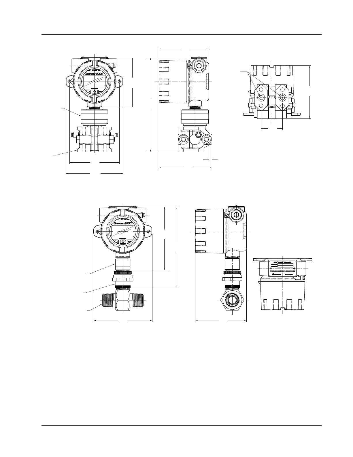
Scanner® 2000 microEFM Section 2
5.00
(127)
1/4-18 NPT
process
connections
4.94
MVT
adapter
(125.5)
9.60
(243.8)
2.125
(53.98)
5.32
(135.1)
MVT
4.96
(126.0)
5.71
(145.0)
5.32
(135.1)
0.32
(8.1)
Figure 2.1—Scanner 2000 with direct-mount MVT (MVT with bottom ports shown)
approx. 6.17
(156.7)
approx. 7.92
(201.2)
3/4” NPT to
1” NPT M/F adapter
Union
Turbine flowmeter
5.71
(145.0)
5.00
(127)
Figure 2.2—Scanner 2000 direct-mounted to a NuFlo turbine owmeter (CSA-approved when direct-mounted
to a NuFlo turbine owmeter or a Barton 7000 Series owmeter)
31
Page 32
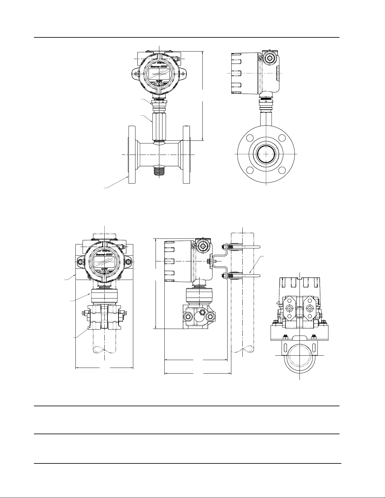
Section 2 Scanner® 2000 microEFM
approx. 9.00
M20 to 3/4”-14 NPT reducer
3/4”-14 NPT to M20 stand-off tube
7000 Series
turbine meter
(228.6)
Figure 2.3—Scanner 2000 direct-mounted to a Barton 7000 Series owmeter (ATEX-approved only when
direct-mounted to a Barton 7000 Series owmeter)
Pole
mount kit
Pole
mount kit
MVT adapter
MVT
6.00
(152.4)
9.60
(243.8)
6.56
(166.6)
6.95
(176.5)
Figure 2.4—Scanner 2000 with MVT, remote-mounted on a 2-in. pole using a NuFlo hardware kit (Part No.
9A-30028004)
Important The vertical pipe mount conguration shown in Figure 2.4 is not recommended for side-
port MVTs when mated with a block manifold for liquid or steam measurement. A horizontal pipe mount should be considered for these installations.
32
Page 33

Scanner® 2000 microEFM Section 2
Measuring Natural Gas via a Differential Pressure Meter
Note This section contains installation guidelines for orice and cone meters. If installing the Scanner 2000
with an averaging pitot tube meter, refer to manufacturer instructions for installation.
Best Practices for Orice and Cone Meter Installation
To ensure measurement accuracy, ensure that the meter run complies with the following AGA-3 and ISO 5167
guidelines, as applicable:
• Do not place unit near vents or bleed holes that discharge corrosive vapors or gases.
• Consider the orientation of the meter run when determining the best position for mounting the Scanner
2000.
– If the Scanner 2000 is mounted to a horizontal pipeline, make sure process connections are at the top
of the line, and mount the Scanner 2000 above the pressure connections at the pipe.
– If the Scanner 2000 is mounted to a vertical pipeline, install the sensor above the differential pressure
source connections, or install a condensate (drip) pot to prevent the accumulation of liquid in interconnecting tubes. Slope all tubing upward at least 1-inch/linear foot to avoid liquid entrapment.
• Mount the Scanner 2000 as near level as possible such that the operator has a clear view of the LCD, and
can access the keypad easily when the enclosure cover is removed. The location should be as free from
vibration as possible.
• Make sure the high port of the sensor (marked “H”) is connected to the upstream side of the meter run.
• Flow should remain subsonic throughout the measuring section and should be single phase.
• Pipe diameters (D) should be between 2 in. (50 mm) and 39 in. (1000 mm) per ISO 5167; or greater than
2 in. (50 mm) per AGA-3.
• Pipe Reynolds numbers must be above 5000.
• d (orice diameter) must be greater than or equal to 0.45 in. (11.5 mm).
• β (diameter ratio) must be greater than or equal to 0.1 and less than or equal to 0.75.
• Gauge lines should be of uniform internal diameter and constructed of material compatible with the uid
being measured. For most applications, the bore should be no smaller than ¼ in. (6 mm) and preferably,
3/8 in. (10 mm) in diameter. The internal diameter should not exceed 1 in. (25 mm). If high-temperature
uids are likely to be encountered, make sure the measuring tube used is rated for the anticipated temperature range.
• Gauge line length should be minimized to help prevent pulsation-induced errors.
• Gauge lines should slope downward to the meter at a minimum of one inch per foot.
• If gauge lines must slope in more than one direction, do not allow more than one bend and install a liquid
or gas trap, as applicable. A liquid trap should be installed at the lowest point in a gas service installation.
• Gauge lines should be supported to prevent sag and vibration.
• Where pulsation is anticipated, full-port manifold valves with a nominal internal diameter consistent with
the gauge lines are recommended.
33
Page 34
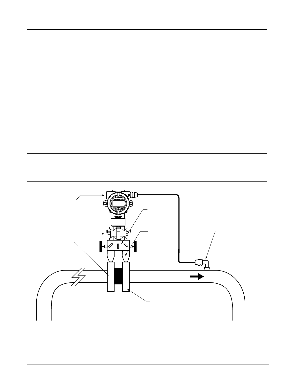
Section 2 Scanner® 2000 microEFM
If the Scanner 2000 is mounted to a cone meter, consider the following best practices in addition to the best
practices listed above.
• Position the cone meter so that there are zero to ve pipe diameters upstream of the meter and zero to
three pipe diameters downstream of the meter.
• Install the meter so that the static pressure tap is upstream of the differential pressure tap. The high side of
the integral Scanner 2000 sensor must also be situated upstream.
• Install shut-off valves directly on the DP meter pressure taps. Choose a shut-off valve that is rated for the
ambient temperatures of the location and the operating pressure of the pipe in which it will be installed,
and for use with dangerous or corrosive uids or gases, if applicable. The valves must not affect the transmission of the differential pressure signal.
Installation Procedure—Direct Mount to Orice Meter or Cone Meter
A Scanner 2000 can be mounted directly to an orice meter or cone meter for gas measurement. The setup
of the meter run and plumbing congurations can vary widely, depending upon the challenges existing on
location. Figure 2.5 shows a typical direct-mount installation.
WARNING HAZARDOUS AREA USE. The Scanner 2000 is certied for hazardous area use only when
installed in accordance with applicable standards and local wiring practices. Carefully
review Hazardous Area Installations, page 27, to determine specic installation requirements (cable glands, conduit seals, signal cable, RTD, etc.).
3/4” conduit connection
(for input/output and
communications)
Pressure ports
(high/low)
H
L
LH
5-valve
manifold
Mounting
adapter
RTD assembly
Flow
Orifice flanges
Figure 2.5—Direct-mount installation in an orice meter run (shown here with an orice meter). The direct-
mount method can be used with a cone meter as well.
34
Page 35

Scanner® 2000 microEFM Section 2
1. Verify that the meter is properly installed in the ow line (per manufacturer’s instructions).
2. Bolt a ange-by-ange 5-valve manifold (as recommended by Cameron) to the Scanner 2000 MVT sen-
sor.
a. Locate the H and L markings on the integral MVT sensor body and position the MVT/manifold as-
sembly so that the upstream side of the ow line can easily be connected to the sensor’s “High” port
and the downstream side of the ow line can be connected to the sensor’s “Low” port. The Scanner
2000 enclosure can be rotated to face the desired direction.
b. Position the manifold so that all valves are accessible from the front of the instrument.
3. Connect the Scanner 2000 and manifold assembly to the differential pressure meter. Hardware require-
ments will vary, depending upon the installation conguration. However, minimally, an adapter is required that can span between the threaded pressure tap/orice ange connector and the non-threaded
manifold. This adapter can be a one-piece stabilizer (often preferred for added strength and stability) or a
short heavy wall pipe nipple attached to a futbol ange (available from Cameron). Use a suitable compound or tape on all threaded process connections.
CAUTION Do not use Teon® tape on the threads of the union, adapter, or pipe plugs. Use of
Teon® tape will void the explosion-proof rating of the instrument.
4. Install the RTD assembly in the thermowell. Route the RTD assembly cable through the conduit opening
in the top of the Scanner 2000 to connect to the main circuit board. A wiring diagram for the RTD assem-
bly is provided in Figure 3.5, page 66. For hazardous areas, review Hazardous Area Installations, page 27.
5. Route any additional inputs/outputs or COM connections, etc. through the conduit opening in the top of
the Scanner 2000. For hazardous areas, review Hazardous Area Installations, page 27.
6. Perform a manifold leak test as described on page 55.
7. Verify the zero offset, if required (and other calibration points, if desired). See the ModWorX™ Pro Soft-
ware User Manual, Part No. 9A-30165025, for complete instructions. See also Zero Offset (Static Pres-
sure or Differential Pressure), page 56, Static Pressure Calibration and Verication, page 56, and Differential
Pressure Calibration and Verication, page 57.
CAUTION Do not put the Scanner into operation until the valves are positioned properly so that
pressure is supplied to both sides of the MVT. For instructions on proper valve positions,
see Placing the Scanner into Operation, page 58.
Installation Procedure—Remote Mount to Orice Meter or Cone Meter
A Scanner 2000 can be mounted remotely and connected to an orice meter or cone meter with tubing for gas
measurement. The setup of the meter run and plumbing congurations can vary widely, depending upon the
challenges existing on location. Figure 2.6 shows a typical remote-mount installation.
WARNING HAZARDOUS AREA USE. The Scanner 2000 is certied for hazardous area use only when
installed in accordance with applicable standards and local wiring practices. Carefully
review Hazardous Area Installations, page 27, to determine specic installation requirements (cable glands, conduit seals, signal cable, RTD, etc.).
35
Page 36
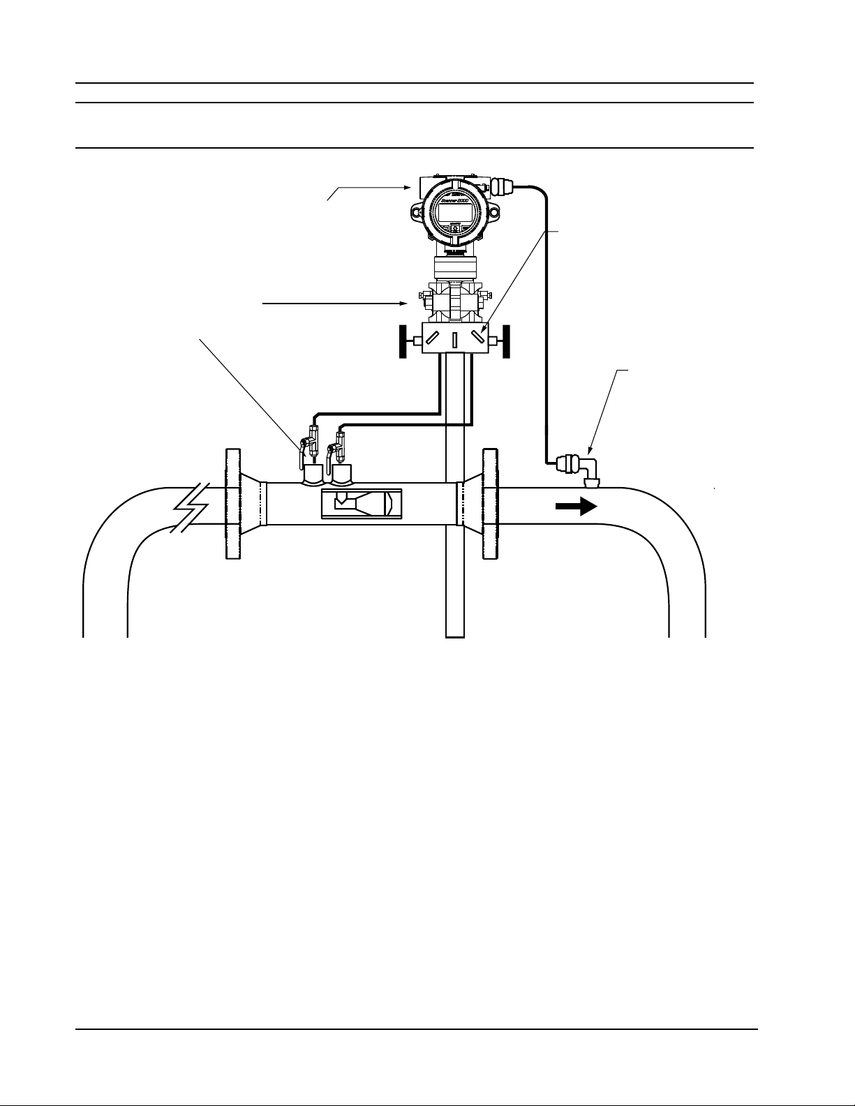
Section 2 Scanner® 2000 microEFM
Note To prevent ttings from turning and/or to avoid putting tension on stainless steel tubing, use a backup
wrench to attach stainless steel tubing to a manifold, shut-off valves, or sensor ports.
3/4” conduit connection
(for input/output and
Manifold
communications)
Pressure ports
H
L
(high/low)
RTD assembly
L
H
Flow
Figure 2.6—Remote-mount gas run installation (shown here with a cone meter). The remote-mount method
can be used with an orice meter as well.
1. Verify that the meter is properly installed in the ow line (per manufacturer’s instructions).
2. Mount the Scanner 2000 to a 2-in. pipe or to a at, vertical surface using bolts and the mounting holes in
the enclosure.
3. Bolt a 5-valve ange-by-NPT manifold (as recommended by Cameron) to the Scanner 2000 MVT sensor.
a. Locate the H and L markings on the integral MVT sensor body and position the MVT/manifold as-
sembly so that the upstream side of the ow line can easily be connected to the sensor’s “High” port
and the downstream side of the ow line can be connected to the sensor’s “Low” port. The Scanner
2000 enclosure can be rotated to face the desired direction.
b. Position the manifold so that all valves are accessible from the front of the instrument.
4. Install tubing and ttings to connect the Scanner 2000 and manifold assembly to the differential pressure
meter, sloping the gauge lines downward to the meter at a minimum of one inch per foot. Use a suitable
compound or tape on all threaded process connections.
36
Page 37

Scanner® 2000 microEFM Section 2
CAUTION Do not use Teon® tape on the threads of the union, adapter, or pipe plugs. Use of
Teon® tape will void the explosion-proof rating of the instrument.
5. Install the RTD assembly in the thermowell. Route the RTD assembly cable through the conduit opening
in the top of the Scanner 2000 to connect to the main circuit board. A wiring diagram for the RTD assem-
bly is provided in Figure 3.5, page 66. For hazardous areas, review Hazardous Area Installations, page 27.
6. Route any additional inputs/outputs or COM connections, etc. through the conduit opening in the top of
the Scanner 2000. For hazardous areas, review Hazardous Area Installations, page 27.
7. Perform a manifold leak test as described on page 55.
8. Verify the zero offset, if required (and other calibration points, if desired). See the ModWorX™ Pro Soft-
ware User Manual, Part No. 9A-30165025, for complete instructions. See also Zero Offset (Static Pres-
sure or Differential Pressure), page 56, Static Pressure Calibration and Verication, page 56, and Differential
Pressure Calibration and Verication, page 57.
CAUTION Do not put the Scanner into operation until the valves are positioned properly so that
pressure is supplied to both sides of the MVT. For instructions on proper valve positions,
see Placing the Scanner into Operation, page 58.
37
Page 38

Section 2 Scanner® 2000 microEFM
Measuring Natural Gas via a Turbine Meter
Best Practices
The Scanner 2000 microEFM calculates gas ow through a turbine meter in accordance with AGA-7 and
API 21.1 industry standards. For optimum performance, ensure that the turbine and Scanner 2000 installation
complies with the industry recommendations listed below:
• Install the turbine owmeter in the meter run such that there are 10 nominal pipe diameters upstream and
ve nominal pipe diameters downstream of the meter. Both inlet and outlet pipe should be of the same
nominal size as the meter.
• Straightening vanes are recommended for eliminating swirl conditions. If used, they should be installed
ve pipe diameters upstream of the meter.
• Where an RTD is used to facilitate compensated gas measurement from a gas turbine meter, locate the
RTD within ve pipe diameters downstream of the meter outlet and upstream of any valve or ow restriction.
Installation Procedure—Remote Mount to a Turbine Meter
A Scanner 2000 can be mounted remotely and connected to a gas turbine meter for measuring gas in
accordance with AGA-7 calculations. Figure 2.7, page 39, shows an installation in which the pressure input
is provided by the integral MVT. Alternatively, if an optional expansion board is installed in the Scanner
2000, an external explosion-proof pressure transducer can be used to supply the pressure. See Installation
Procedure—Direct Mount to a Turbine Meter (CSA Compliant), page 40, for more information.
The setup of the meter run and plumbing congurations can vary widely, depending upon the challenges
existing on location.
WARNING HAZARDOUS AREA USE. The Scanner 2000 is certied for hazardous area use only when
installed in accordance with applicable standards and local wiring practices. Carefully
review Hazardous Area Installations, page 27, to determine specic installation requirements (cable glands, conduit seals, signal cable, RTD, etc.).
To connect the Scanner 2000 to a turbine meter, perform the following steps:
1. Verify that the owmeter and magnetic pickup are installed in the ow line.
2. Mount the Scanner 2000 to a 2-in. pipe or to a at, vertical surface using bolts and the mounting holes in
the enclosure.
3. Bolt a 3-valve ange-by-NPT manifold (as recommended by Cameron) to the Scanner 2000 MVT sensor.
Position the manifold so that all valves are accessible from the front of the instrument.
4. Connect the pressure port of the turbine meter to either manifold process port with tubing. The unused
pressure port can be used as a “vent” as required. Always leave the equalizer valves open to allow pressure to both sides of the MVT. Use a suitable compound or tape on all threaded process connections.
CAUTION Do not use Teon® tape on the threads of the union, adapter, or pipe plugs. Use of
Teon® tape will void the explosion-proof rating of the instrument.
38
Page 39
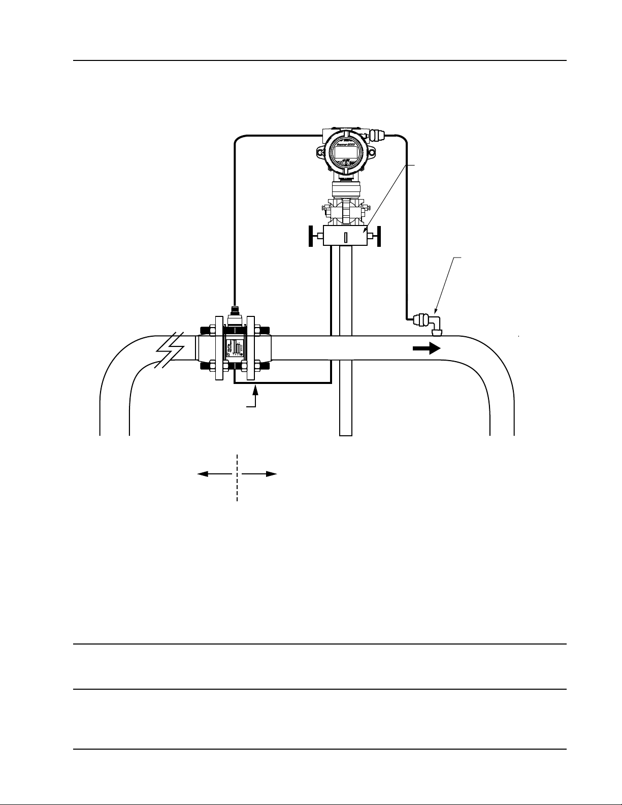
Scanner® 2000 microEFM Section 2
5. Remove the plug from the conduit opening in the top of the Scanner 2000 enclosure, route the turbine sig-
nal cable through the opening, and connect it to the main circuit board. A wiring diagram for the turbine
input is provided in Figure 3.4, page 65. For hazardous areas, review Hazardous Area Installations, page 27.
Manifold
L
H
RTD assembly
Flow
Static pressure input
(manifold equalizer valve
must remain open)
10 pipe diameters
upstream
Figure 2.7—Remote-mount installation in an AGA-7 turbine meter run
6. Install the RTD assembly in the thermowell. Remove the plug from the other conduit opening in the top
of the Scanner 2000 enclosure, route the RTD assembly cable through the conduit opening in the top of
the Scanner 2000, and connect it to the main circuit board. A wiring diagram for the RTD assembly is
provided in Figure 3.5, page 66. For hazardous areas, review Hazardous Area Installations, page 27.
7. Zero the static pressure and recalibrate the static pressure, if required. See the ModWorX™ Pro Software
User Manual, Part No. 9A-30165025, for complete instructions. See also Zero Offset (Static Pressure or
Differential Pressure), page 56, and Static Pressure Calibration and Verication, page 56.
CAUTION Do not put the Scanner into operation until the valves are positioned properly so that
pressure is supplied to both sides of the MVT. For instructions on proper valve positions,
see Placing the Scanner into Operation, page 58.
5 pipe diameters
downstream
39
Page 40
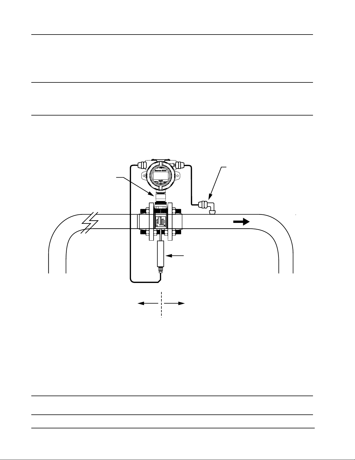
Section 2 Scanner® 2000 microEFM
Installation Procedure—Direct Mount to a Turbine Meter (CSA Compliant)
A Scanner 2000 without the MVT bottomworks can be mounted directly to a gas turbine meter for measuring
natural gas. A pipe adapter and union are attached to the Scanner, allowing a direct connection to the turbine
meter.
WARNING HAZARDOUS AREA USE. The Scanner 2000 is certied for hazardous area use only when
installed in accordance with applicable standards and local wiring practices. Carefully
review Hazardous Area Installations, page 27, to determine specic installation requirements (cable glands, conduit seals, signal cable, RTD, etc.).
An external pressure transducer is required for converting the pressure to a 4-20 mA or 1-5V signal, and the
Scanner 2000 must be equipped with the optional expansion board, which provides the analog input necessary
to receive the pressure signal from the transducer. If installed in a Div. 1 hazardous area, the transducer must
be explosion-proof.
RTD assembly
Adapter/union
(CSA-approved)
Flow
External pressure transducer
(connected to meter
pressure port)
10 pipe diameters
upstream (minimum)
Figure 2.8—Direct-mount installation for use with a gas turbine meter
To connect the Scanner 2000 to a turbine meter using this method, perform the following steps:
1. Position the Scanner 2000 above the gas turbine owmeter.
2. Plug the Scanner 2000 cable connector into the magnetic pickup of the turbine meter and hand-tighten the
knurled nut on the connector.
3. Screw the Scanner 2000 onto the owmeter threads surrounding the magnetic pickup with the display facing the desired direction.
5 pipe diameters
downstream (minimum)
CAUTION Do not use Teon® tape on the threads of the union, adapter, or pipe plugs. Use of
Teon® tape will void the explosion-proof rating of the instrument.
40
Page 41

Scanner® 2000 microEFM Section 2
4. Tighten all sections of the pipe union.
5. Connect the pressure port of the turbine meter to the external pressure transducer.
6. Remove the plug from the conduit opening in the top of the Scanner 2000 enclosure, route the cable from
the pressure transducer through the opening, and connect it to the analog input terminal of the expansion
circuit board. A wiring diagram for the analog input is provided in Figure A.15, page A-10. For hazardous
areas, review Hazardous Area Installations, page 27.
7. Install the RTD assembly in the thermowell. Remove the plug from the unused conduit opening in the
top of the Scanner 2000 enclosure, route the RTD assembly cable through the conduit opening in the top
of the Scanner 2000, and connect it to the main circuit board. A wiring diagram for the RTD assembly is
provided in Figure 3.5, page 66. For hazardous areas, review Hazardous Area Installations, page 27.
41
Page 42

Section 2 Scanner® 2000 microEFM
Measuring Steam via a Differential Pressure Meter
Note This section contains installation guidelines for orice and cone meters. If installing the Scanner 2000
with an averaging pitot tube meter, refer to manufacturer instructions for installation.
Best Practices
The Scanner 2000 calculates steam ow in accordance with IF-97, AGA-3, and ISO-5167 industry standards.
For optimum performance, ensure that the installation complies with the following industry recommendations:
Condensate pots
• A condensate pot for a small-volume transducer like the Scanner 2000 MVT can be a simple pipe tee,
oriented so that one port extends downward (into the cold leg), the opposite port extends upward and is
closed by a pipe cap or blowdown valve, and the tee extends horizontally into the hot leg.
• The pots should be the highest point in the system.
• The pots should be mounted at the same level, and one or both should be adjustable vertically to remove
zero shifts in the differential pressure measurement.
Hot legs
• Hot legs should be large diameter (3/8 in. or 1/2 in., if possible)
• Hot legs should be as short as possible. If these sections must be more than 1 ft. in length, insulate them.
• Elbows and bends should not form any traps in which liquid can accumulate.
• Hot legs should be sloped along their entire length to allow liquids to drain back into the pipe.
Cold legs
• Cold legs should enter the multi-variable sensor through its side ports.
• Cold legs should be a minimum of 2 ft in length to allow proper convection cooling and should be run
horizontally with a slope of approximately 1 inch per foot to allow air bubbles to oat up into the pots.
• Elbows and bends should not form any traps for air bubbles.
• Cold legs should be lled with a suitable antifreeze. Dibutyl phthalate is recommended.
Antifreeze
• Dibutyl phthalate (DBP) has the following advantages over glycol antifreeze:
– DBP doesn’t mix with water, and so doesn’t become dilute over time; its specic gravity doesn’t shift.
– It is slightly denser than water, so it will stay in the pot permanently.
– It is non-ammable.
– It is much less toxic than glycol.
– It is available from industrial suppliers.
Valves
• Use only full-opening block valves that are rated for steam service.
• Use only blowdown valves that are rated for steam service. Periodic blowdowns are recommended for
preventing buildup of scale.
42
Page 43
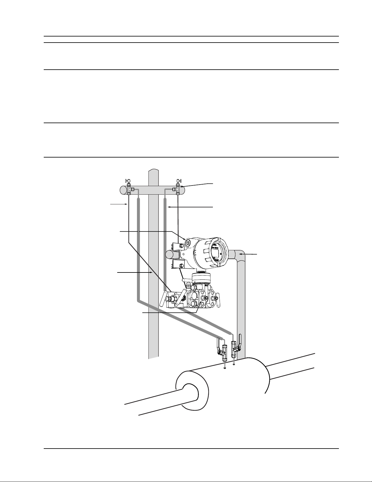
Scanner® 2000 microEFM Section 2
CAUTION Before starting the system, remove the caps and add water or antifreeze if necessary to
completely ll the pots and cold legs. Air trapped in the lines will produce errors in differential pressure measurements.
Installation Procedure—Remote Mount to Orice Meter or Cone Meter
A Scanner 2000 can be mounted remotely and connected to an orice meter or cone meter with tubing for
steam measurement. The setup of the meter run and plumbing congurations can vary widely, depending
upon the challenges existing on location.
WARNING HAZARDOUS AREA USE. The Scanner 2000 is certied for hazardous area use only when
installed in accordance with applicable standards and local wiring practices. Carefully
review Hazardous Area Installations, page 27, to determine specic installation requirements (cable glands, conduit seals, signal cable, RTD, etc.).
Condensate pot (pipe tee
with blowdown valve attached)
Long cold legs protect the
sensor from extreme process
temperatures
3/4 in. conduit connection for
input/output & communications
Cold legs connect to manifold
(slope to eliminate air trap)
MVT vent (use for
for filling cold legs)
Hot legs, insulated to within 1 ft of condensate pot
(1/2 in. diameter recommended)
Horizontal pole mount provides
clearance for block manifold
Figure 2.9—Remote-mount steam run installation (shown here with a cone meter). The remote-mount method
can be used with an orice meter as well.
43
Page 44

Section 2 Scanner® 2000 microEFM
CAUTION When measuring steam, process connections must be designed to eliminate air pock-
ets. This is achieved by making sure all tubing in the cold legs slopes upward. A sideport MVT and block manifold (shown in Figure 2.9) is recommended to help prevent air
bubbles from being trapped in the sensor.
If a bottom-port MVT is used, the bottom process ports must be plugged or replaced with
a drain valve, and side vents must be used for process connections. A block manifold is
not recommended for use with bottom port MVTs. Contact a Cameron eld representative
for assistance.
1. Verify that the meter is properly installed in the ow line (per manufacturer’s instructions).
2. Mount the Scanner 2000 to a 2-in. pipe or to a at, vertical surface using bolts and the mounting holes in
the enclosure. A horizontal pipe is recommended, as additional hardware may be required for a vertical
pipe mount to provide clearance for the manifold block.
3. Mount a set of pipe tees (which serve as condensate pots) typically on either side of the Scanner 2000 at an
elevation above the process connections of the Scanner 2000 MVT (for proper drainage). They should be a
considerable distance (4 ft) from the sensor ports, but as close as possible to the pressure taps on the meter.
4. Install a pipe cap or a blowdown valve that is rated for steam service at the top of each pipe tee. A blowdown valve is recommended when the steam passing through the meter is known to be dirty.
5. Install tubing and ttings to connect the high-pressure and low-pressure taps of the DP meter to the pipe
tees. This section is typically referred to as the hot legs of the installation, as this section of tubing encounters steam at its highest temperature. Install a shut-off valve near the high and low ports of the DP
meter. Use a suitable compound or tape on all threaded process connections.
6. Route any additional inputs/outputs or COM connections, etc. through the conduit opening in the top of
the Scanner 2000. For hazardous areas, review Hazardous Area Installations, page 27.
Note: To prevent ttings from turning and/or to avoid putting tension on stainless steel tubing, use a backup
wrench to attach stainless steel tubing to shut-off valves, or sensor ports.
CAUTION Whenever possible, locate the hot legs of a steam installation behind the Scanner 2000
safely out of the operator’s normal reach. This will help prevent accidental burns.
7. Install tubing to connect the high-pressure and low-pressure process connections of the block manifold to
the pipe tees installed in step 3. This tubing section is typically referred to as the cold legs of the installa-
tion, since it is lled with water.
8. To eliminate air bubbles, ll the cold legs with water or other ll uid from the lowest point in the system,
typically the MVT, using the following steps:
a. Open the blowdown valve or remove the lling plug from one of the pipe tees/condensate pots.
b. Open the equalizer and bypass/block valves on the block manifold. Make sure the vent valve is
closed.
c. Remove the corresponding (high pressure or low pressure) vent screw from the side of the MVT and
insert a tting to allow connection of a hand pump or funnel. If a funnel is used, attach a length of
Tygon tubing that is long enough to elevate the funnel well above the condensate pot to force the uid
up the legs.
44
Page 45

Scanner® 2000 microEFM Section 2
d. Connect a hand pump or funnel to the tting.
e. Pour ll liquid into the funnel or pump it into the cold leg, tapping the cold leg occasionally to dis-
lodge any bubbles.
f. Observe the pipe tee/condensate pot and stop pouring when the ll liquid is visible at the top and no
air bubbles can be seen.
g. Remove the tting from the vent of the MVT and quickly replace the vent screw and tighten.
h. Close the blowdown valve or replace the lling plug from one of the pipe tees/condensate pots.
i. Repeat steps a through h for the other cold leg.
9. To eliminate an offset of the differential pressure reading, open the equalizer valves on the block manifold,
remove the caps from the seal pots, and adjust either seal pot vertically to bring the water levels to the exact
same elevation.
10. Perform a manifold leak test as described on page 55.
11. Verify the zero offset, if required (and other calibration points, if desired). See the ModWorX™ Pro Soft-
ware User Manual, Part No. 9A-30165025, for complete instructions. See also Zero Offset (Static Pressure
or Differential Pressure), page 56, Static Pressure Calibration and Verication, page 56, and Differential Pres-
sure Calibration and Verication, page 57.
CAUTION Do not put the Scanner into operation until the valves are positioned properly so that
pressure is supplied to both sides of the MVT. For instructions on proper valve positions,
see Placing the Scanner into Operation, page 58.
45
Page 46

Section 2 Scanner® 2000 microEFM
Measuring Liquid via a Differential Pressure Meter
Note This section contains installation guidelines for orice and cone meters. If installing the Scanner 2000
with an averaging pitot tube meter, refer to manufacturer instructions for installation.
Best Practices
To ensure measurement accuracy, ensure that the meter run complies with the following AGA-3 and ISO 5167
guidelines, as applicable:
• Do not place unit near vents or bleed holes that discharge corrosive vapors or gases.
• Consider the orientation of the meter run when determining the best position for mounting the Scanner.
– If the Scanner 2000 is mounted to a horizontal pipeline, make sure process connections are horizon-
tal with the pipeline, or sloped downwards towards the Scanner. Mount the Scanner 2000 below the
pressure taps at the pipe. Use the side (upper) ports as process connections and the bottom ports for
draining and lling the DP housings.
– If the Scanner 2000 is mounted to a vertical pipeline, install the sensor below the differential pressure
source connections. Slope all tubing downward at least 1-inch/linear foot to avoid gas entrapment.
• Mount the Scanner 2000 as near level as possible such that the operator has a clear view of the LCD, and
can access the keypad easily when the enclosure cover is removed. The location should be as free from
vibration as possible.
• Make sure the high port of the sensor (marked “H”) is connected to the upstream side of the meter run.
• Pipe diameters (D) should be between 2 in. (50 mm) and 39 in. (1000 mm) per ISO 5167; or greater than
2 in. (50 mm) per AGA-3.
• Pipe Reynolds numbers must be above 5000. Avoid high-viscosity liquids (greater than 15 cP).
• d (orice diameter) must be greater than or equal to 0.45 in. (11.5 mm).
• Orice β (diameter ratio) must be greater than or equal to 0.1 and less than or equal to 0.75.
• Gauge lines should be of uniform internal diameter and constructed of material compatible with the uid
being measured. For most applications, the bore should be no smaller than ¼ in. (6 mm) and preferably,
3/8 in. (10 mm) in diameter. The internal diameter should not exceed 1 in. (25 mm). If high-temperature
uids are likely to be encountered, make sure the measuring tube used is rated for the anticipated temperature range.
• If there is possibility of freezing, the gauge lines can be lled with a suitable seal liquid. The seal liquid
should be somewhat denser than the process uid, should not dissolve in it, should have a sufciently low
freezing point, and should be non-toxic. Alternatively, heat tracing can be used.
• Gauge line length should be minimized to help prevent pulsation-induced errors.
• Gauge lines should slope upward to the meter at a minimum of one inch per foot.
• If gauge lines must slope in more than one direction, do not allow more than one bend and install a gas
trap.
• Gauge lines should be supported to prevent sag and vibration.
• Where pulsation is anticipated, full-port manifold valves with a nominal internal diameter consistent with
the gauge lines are recommended.
If the Scanner 2000 is mounted to a cone meter, consider the following guidelines in addition to the best
46
Page 47
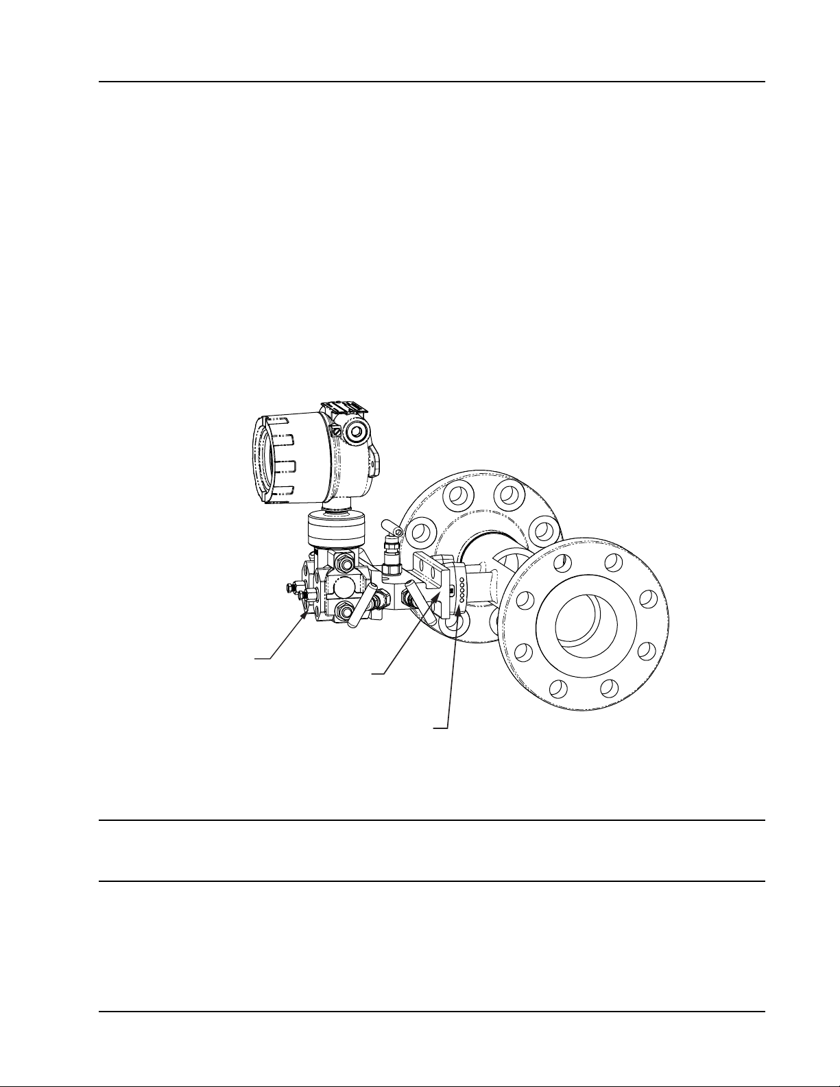
Scanner® 2000 microEFM Section 2
practices listed above.
• Position the cone meter so that there are zero to ve pipe diameters upstream of the meter and zero to
three pipe diameters downstream of the meter.
• Install the meter so that the static pressure tap is upstream of the differential pressure tap. The high side of
the integral Scanner 2000 sensor must also be situated upstream.
• Install shut-off valves directly on the DP meter pressure taps. Choose a shut-off valve that is rated for the
ambient temperatures of the location and the operating pressure of the pipe in which it will be installed,
and for use with dangerous or corrosive uids or gases, if applicable. The valves must not affect the transmission of the differential pressure signal.
Installation Procedure—Direct Mount to Orice Meter or Cone Meter
A Scanner 2000 can be mounted directly to an orice meter or cone meter for liquid measurement using a
side-port MVT, a block manifold and two football ange adapters (Figure 2.10). The setup of the meter run
and plumbing congurations can vary widely, depending upon the challenges existing on location.
MVT with
side ports
Figure 2.10—Direct-mount liquid run installation (shown here with a cone meter). Downstream RTD is not
shown.
CAUTION When measuring liquid with a direct-mount Scanner 2000, process connections must be
parallel to the horizontal centerline of the meter, or below the centerline to eliminate air
pockets.
Block
manifold
Adapter
(2 typ.)
1. Verify that the meter is properly installed in the ow line (per manufacturer’s instructions).
2. Screw a football ange adapter onto each meter pressure tap using pipe tape or pipe dope to seal the
threads.
47
Page 48

Section 2 Scanner® 2000 microEFM
3. Align the bolt holes in the Scanner 2000 MVT and manifold, and install bolts to mate these components
to the football anges, using o-rings as appropriate. Torque the bolts to the manufacturer’s specication.
4. Route any additional inputs/outputs or COM connections, etc. through the conduit opening in the top of
the Scanner 2000. For hazardous areas, review Hazardous Area Installations, page 27.
5. Verify that all manifold valves are closed, and ll the meter with process uid.
6. Loosen one of the vent screws in the side of the MVT.
7. Open the equalizer valves and the vent valve on the manifold.
8. Slowly open one of the bypass/block valves on the manifold. Process uid should immediately spurt from
the MVT vent.
9. When air bubbles are no longer visible around the MVT vent, tighten the MVT vent screw.
10. Loosen the other vent screw in the side of the MVT, and repeat steps 7 through 9.
11. Perform a manifold leak test as described on page 55.
12. Verify the zero offset, if required (and other calibration points, if desired). See the ModWorX™ Pro Software User Manual, Part No. 9A-30165025, for complete instructions. See also Zero Offset (Static Pressure
or Differential Pressure), page 56, Static Pressure Calibration and Verication, page 56, and Differential Pres-
sure Calibration and Verication, page 57.
CAUTION Do not put the Scanner into operation until the valves are positioned properly so that
pressure is supplied to both sides of the MVT. For instructions on proper valve positions,
see Placing the Scanner into Operation, page 58.
Installation Procedure—Remote Mount to Orice Meter or Cone Meter
A Scanner 2000 can be mounted remotely and connected to an orice meter or cone meter with tubing for
liquid measurement (Figure 2.11). The setup of the meter run and plumbing congurations can vary widely,
depending upon the challenges existing on location.
WARNING HAZARDOUS AREA USE. The Scanner 2000 is certied for hazardous area use only when
installed in accordance with applicable standards and local wiring practices. Carefully
review Hazardous Area Installations, page 27, to determine specic installation requirements (cable glands, conduit seals, signal cable, RTD, etc.).
CAUTION When measuring liquid, process connections must be designed to eliminate air pockets.
This is achieved by mounting the sensor below the metering device and sloping all tubing downward from the meter to the sensor. A side-port MVT and block manifold (shown
in Figure 2.11) is recommended to help prevent air bubbles from being trapped in the
sensor.
If a bottom-port MVT is used, the bottom process ports must be plugged or replaced with
a drain valve, and side vents must be used for process connections. A block manifold is
not recommended for use with bottom port MVTs. Contact a Cameron eld representative
for assistance.
48
Page 49
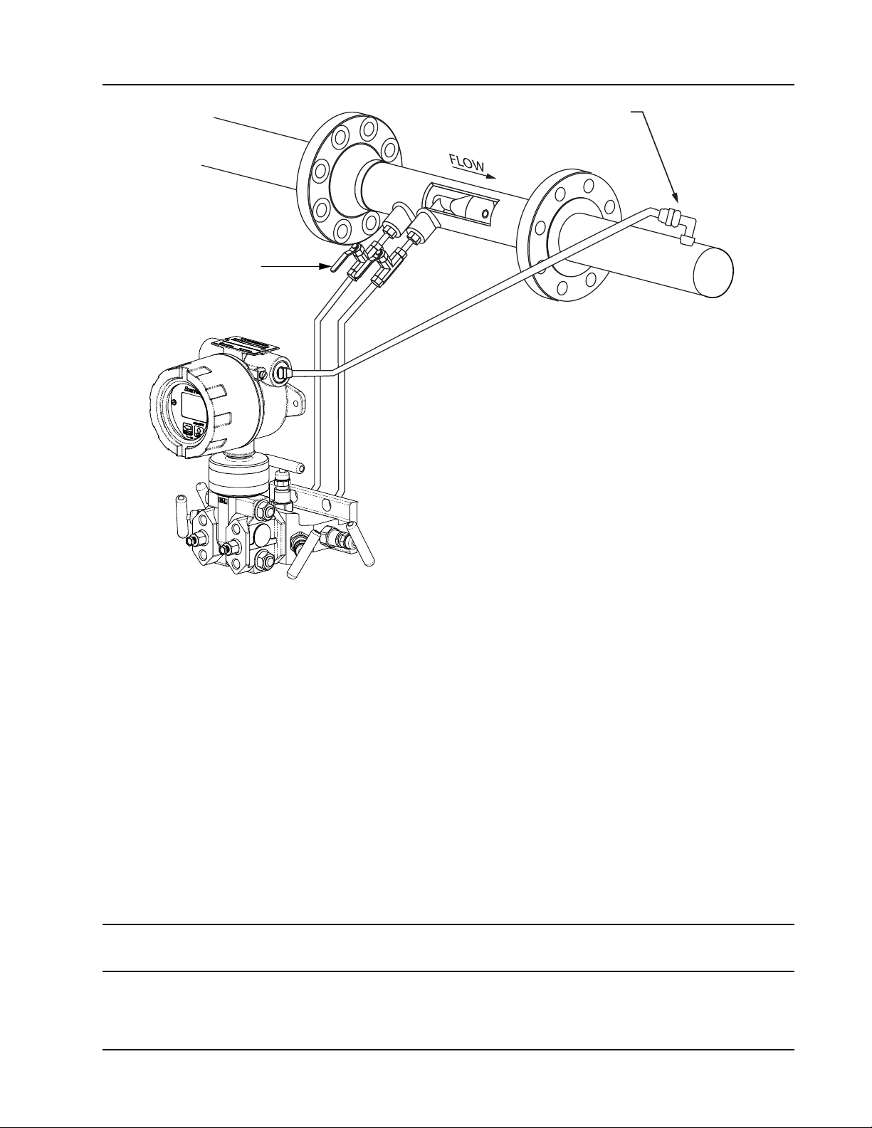
Scanner® 2000 microEFM Section 2
RTD assembly
Shut-off valves
throttle flow to
the manifold
and MVT
Positioning of sensor below the
meter and slope of tubing helps
prevent gas bubbles from entering
the liquid
Figure 2.11—Remote-mount liquid run installation (shown here with a cone meter). The remote-mount method
can be used with an orice meter as well.
1. Verify that the meter is properly installed in the ow line (per manufacturer’s instructions).
2. Mount the Scanner 2000 to a 2-in. pipe or to a at, vertical surface using bolts and the mounting holes in
the enclosure. A horizontal pipe is recommended, as additional hardware may be required for a vertical
pipe mount to provide clearance for the manifold block.
3. Install tubing and ttings to connect the high-pressure and low-pressure taps of the DP meter to the pro-
cess connections of the block manifold. Install a pair of shut-off valves near the high and low ports of the
DP meter. Use a suitable compound or tape on all threaded process connections.
4. Install the RTD assembly in the thermowell. Remove the plug from a conduit opening in the top of the
Scanner 2000 enclosure, route the RTD assembly cable through the conduit opening and connect it to the
main circuit board. A wiring diagram for the RTD assembly is provided in Figure 3.5, page 66. For hazard-
ous areas, review Hazardous Area Installations, page 27.
5. Route any additional inputs/outputs or COM connections, etc. through the conduit opening in the top of
the Scanner 2000. For hazardous areas, review Hazardous Area Installations, page 27.
Note To prevent ttings from turning and/or to avoid putting tension on stainless steel tubing, use a backup
wrench to attach stainless steel tubing to shut-off valves, or sensor ports.
6. To eliminate air bubbles in the MVT, manifold, and legs connecting them to the meter, ll the legs with
uid. Choose a uid that is safe for the environment, and stable when depressurized.
49
Page 50

Section 2 Scanner® 2000 microEFM
Important If the process uid does not present an environmental risk and is stable when depressur-
ized, it may be used to bleed air from the lines. If the process uid can contaminate the
environment, or is highly volatile when depressurized as with liquied gases, a different
seal uid should be used to ll the legs. An ideal seal uid is one that does not dissolve
in the process uid.
Bleeding with Process Fluid
g. Make sure the shut-off valves in the tubing near the meter pressure taps are closed, and the meter is
lled with process uid.
h. Open the equalizer and bypass/block valves on the block manifold. Make sure the vent valve is
closed.
i. Open one of the shut-off valves near the meter.
j. Slowly loosen the corresponding vent screw on the MVT, and throttle the rate of ow from the vent
with the shut-off valve.
k. When air bubbles are no longer visible around the MVT vent, tighten the MVT vent screw.
l. Repeat steps a through e for the other leg.
Bleeding with a Different Seal Fluid
m. Make sure the shut-off valves in the tubing near the pressure taps are open.
n. Open the equalizer and bypass/block valves on the block manifold. Make sure the vent valve is
closed.
o. Remove the vent screw from one side of the MVT and insert a tting to allow connection of a hand
pump or funnel. If a funnel is used, attach a length of Tygon tubing that is long enough to elevate the
funnel well above the meter pressure taps to force the uid up the legs.
p. Connect a hand pump or funnel to the tting.
q. Estimate the amount of ll uid required to ll the tubing and push any air bubbles into the meter.
r. Pour ll liquid into the funnel, tapping the tubing occasionally to dislodge any bubbles.
s. When the leg is full of uid, remove the tting from the vent of the MVT and quickly replace the vent
screw and tighten.
t. Repeat steps a through g for the other leg.
6. Perform a manifold leak test as described on page 55.
7. Verify the zero offset, if required (and other calibration points, if desired). See the ModWorX™ Pro Software User Manual, Part No. 9A-30165025, for complete instructions. See also Zero Offset (Static Pressure
or Differential Pressure), page 56, Static Pressure Calibration and Verication, page 56, and Differential Pres-
sure Calibration and Verication, page 57.
CAUTION Do not put the Scanner into operation until the valves are positioned properly so that
pressure is supplied to both sides of the MVT. For instructions on proper valve positions,
see Placing the Scanner into Operation, page 58.
50
Page 51
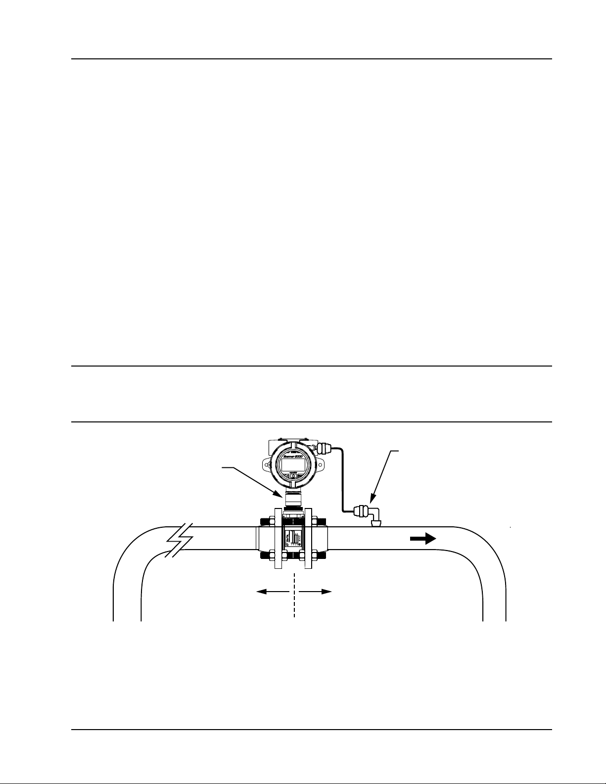
Scanner® 2000 microEFM Section 2
Measuring Compensated Liquid via a Turbine Meter
Best Practices
The Scanner 2000 microEFM calculates compensated liquid ow through a turbine meter in accordance with
API-2540 and the measurement principles upon which the AGA-7 standard is based. The user supplies a
linear or multi-point calibration factor, and the instrument performs the required compensation calculations,
based on the RTD input.
For optimum performance, ensure that the turbine and Scanner 2000 installation complies with the industry
recommendations listed below:
• Install the turbine owmeter in the meter run such that there are at least 10 nominal pipe diameters up-
stream and ve nominal pipe diameters downstream of the meter. Both inlet and outlet pipe should be of
the same nominal size as the meter.
• Straightening vanes are recommended for eliminating swirl conditions. If used, they should be installed
ve pipe diameters upstream of the meter.
Installation Procedure—Direct Mount to a Turbine Meter (CSA Compliant)
A Scanner 2000 without the MVT bottomworks can be mounted directly to a liquid turbine meter for
measuring liquid (Figure 2.12). A pipe adapter and union are attached to the Scanner, allowing a direct
connection to the turbine meter.
WARNING HAZARDOUS AREA USE. The Scanner 2000 is certied for hazardous area use only when
installed in accordance with applicable standards and local wiring practices. Carefully
review Hazardous Area Installations, page 27, to determine specic installation requirements (cable glands, conduit seals, signal cable, RTD, etc.).
RTD assembly
Adapter/union
(CSA-approved)
Flow
10 pipe diameters
upstream
Figure 2.12—Direct-mount installation for use with a Barton 7000 Series meter
5 pipe diameters
downstream
51
Page 52
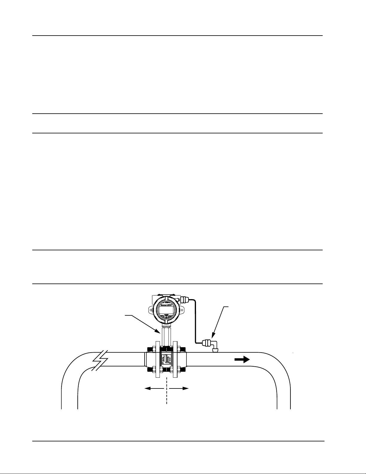
Section 2 Scanner® 2000 microEFM
Flow
Turbine meter pickup
extension (ATEX-approved)
10 pipe diameters
upstream (minimum)
5 pipe diameters
downstream (minimum)
ATEX-approved
explosion-proof RTD
To connect the Scanner 2000 to a liquid turbine meter using this method, perform the following steps:
1. Position the Scanner 2000 above the owmeter.
2. Plug the Scanner 2000 cable connector into the magnetic pickup of the turbine meter and hand-tighten the
knurled nut on the connector.
3. Screw the Scanner 2000 onto the owmeter threads surrounding the magnetic pickup with the display facing the desired direction.
CAUTION Do not use Teon® tape on the threads of the union, adapter, or pipe plugs. Use of
Teon® tape will void the explosion-proof rating of the instrument.
4. Tighten all sections of the pipe union.
5. Install the RTD assembly in the thermowell. Remove the plug from a conduit opening in the top of the
Scanner 2000 enclosure, route the RTD assembly cable through the conduit opening and connect it to the
main circuit board. A wiring diagram for the RTD assembly is provided in Figure 3.5, page 66. For hazard-
ous areas, review Hazardous Area Installations, page 27.
Installation Procedure—Direct Mount to a Barton 7000 Series Turbine Meter (ATEX Compliant)
A Scanner 2000 without the MVT bottomworks can be mounted directly to a Barton 7000 series turbine meter
for measuring liquid (Figure 2.13). A stainless steel turbine meter pickup extension supports the Scanner 2000
and provides the elevation necessary for good visibility of the display.
WARNING HAZARDOUS AREA USE. The Scanner 2000 is certied for hazardous area use only when
installed in accordance with applicable standards and local wiring practices. Carefully
review Hazardous Area Installations, page 27, to determine specic installation requirements (cable glands, conduit seals, signal cable, RTD, etc.).
Figure 2.13—Direct-mount installation for use with a Barton 7000 Series meter
52
Page 53

Scanner® 2000 microEFM Section 2
To connect the Scanner 2000 to a turbine meter using this method, perform the following steps:
1. Position the Scanner 2000 and pickup extension assembly above the owmeter.
2. Plug the Scanner 2000 cable connector into the magnetic pickup of the turbine meter and hand-tighten the
knurled nut on the connector.
3. Screw the Scanner 2000/pickup extension assembly onto the owmeter threads surrounding the magnetic
pickup with the display facing the desired direction, and tighten.
CAUTION Do not use Teon® tape on the threads of the union, adapter, or pipe plugs. Use of
Teon® tape will void the explosion-proof rating of the instrument.
4. Install the RTD assembly in the thermowell. Remove the plug from a conduit opening in the top of the
Scanner 2000 enclosure, route the RTD assembly cable through the conduit opening and connect it to the
main circuit board. A wiring diagram for the RTD assembly is provided in Figure 3.5, page 66.For hazardous areas, review Hazardous Area Installations, page 27.
53
Page 54
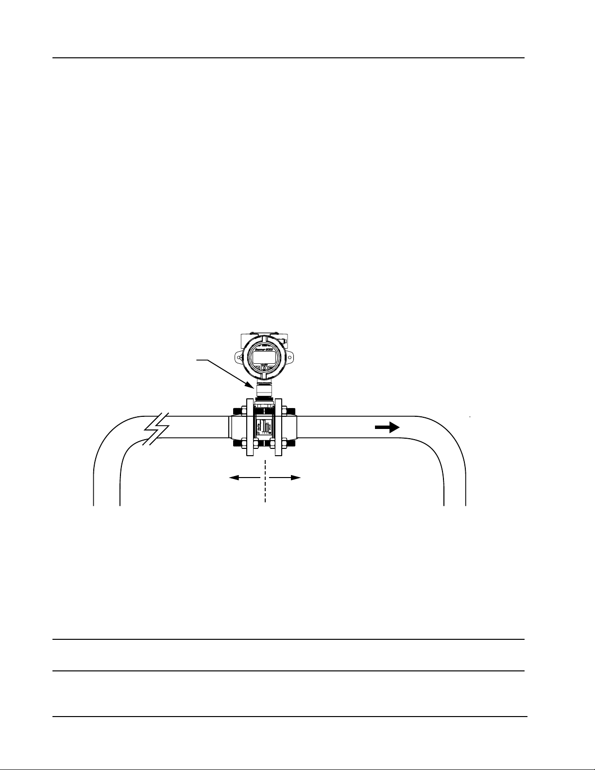
Section 2 Scanner® 2000 microEFM
Measuring Uncompensated Liquid via a Turbine Meter
Best Practices
The Scanner 2000 microEFM calculates uncompensated liquid ow through a turbine meter in accordance
with API MPMS, Chapter 5, Section 3, Measurement of Liquid Hydrocarbons by Turbine Meters. For
optimum performance, ensure that the turbine and Scanner 2000 installation complies with the industry
recommendations listed below:
• Install the turbine owmeter in the meter run such that there are at least 10 nominal pipe diameters upstream and ve nominal pipe diameters downstream of the meter. Both inlet and outlet pipe should be of
the same nominal size as the meter.
• Straightening vanes are recommended for eliminating swirl conditions. If used, they should be installed
ve pipe diameters upstream of the meter.
Installation Procedure—Direct Mount to a Turbine Meter (CSA Compliant)
A Scanner 2000 without the MVT bottomworks can be mounted directly to a liquid turbine meter for
measuring liquid (Figure 2.14). A pipe adapter and union are attached to the Scanner, allowing a direct
connection to the turbine meter.
Adapter/union
(CSA-approved)
Flow
10 pipe diameters
upstream (minimum)
Figure 2.14—Direct-mount installation for use with a Barton 7000 Series meter
To connect the Scanner 2000 to a liquid turbine meter using this method, perform the following steps:
1. Position the Scanner 2000 above the owmeter.
2. Plug the Scanner 2000 cable connector into the magnetic pickup of the turbine meter and hand-tighten the
knurled nut on the connector.
3. Screw the Scanner 2000 onto the owmeter threads surrounding the magnetic pickup with the display facing the desired direction.
5 pipe diameters
downstream (minimum)
CAUTION Do not use Teon® tape on the threads of the union, adapter, or pipe plugs. Use of
Teon® tape will void the explosion-proof rating of the instrument.
4. Tighten all sections of the pipe union.
54
Page 55
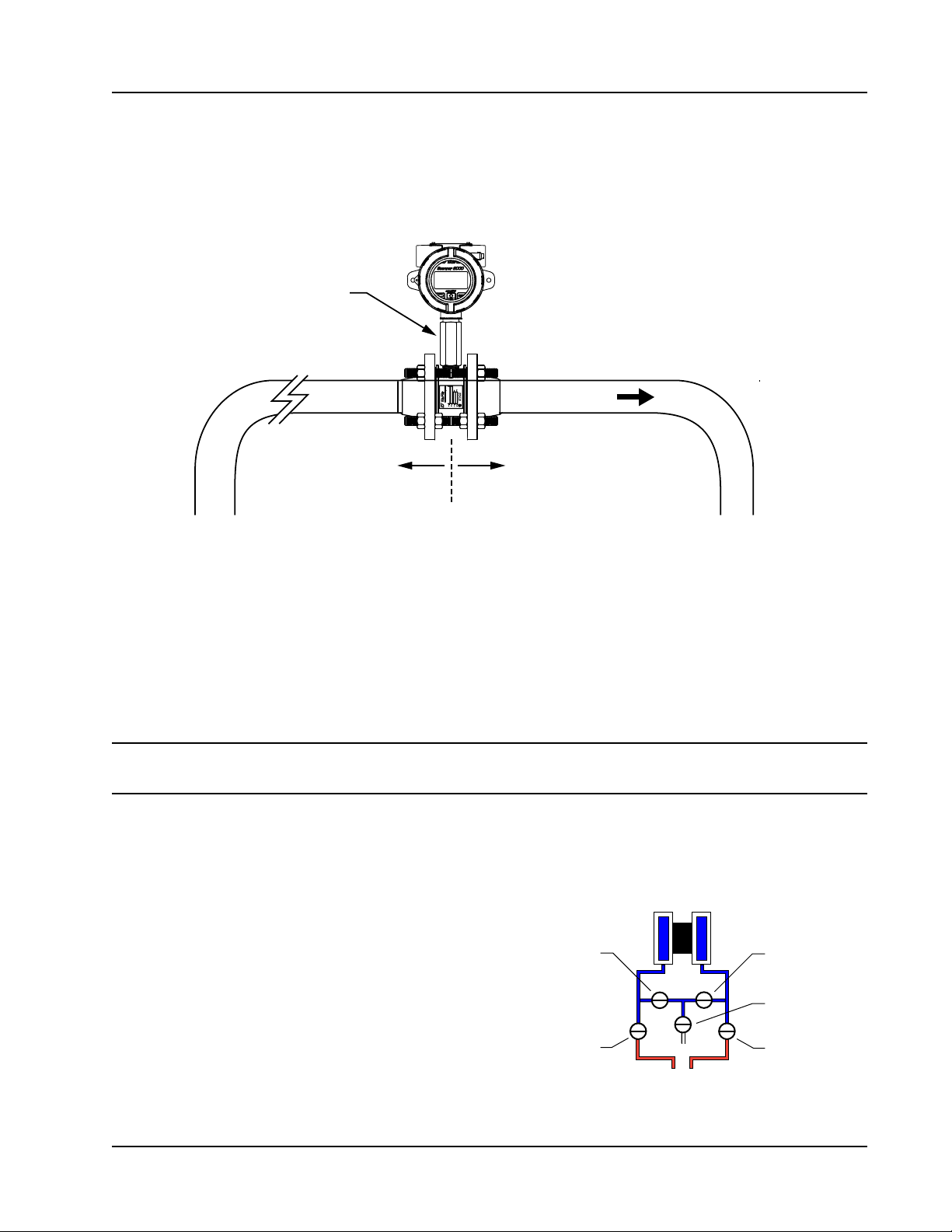
Scanner® 2000 microEFM Section 2
Installation Procedure—Direct Mount to a Barton 7000 Series Turbine Meter (ATEX Compliant)
A Scanner 2000 without the MVT bottomworks can be mounted directly to a Barton 7000 series turbine meter
for measuring liquid (Figure 2.15). A stainless steel turbine meter pickup extension supports the Scanner 2000
and provides the elevation necessary for good visibility of the display.
Turbine meter pickup
extension (ATEX-approved)
Flow
10 pipe diameters
upstream (minimum)
Figure 2.15—Direct-mount installation for use with a Barton 7000 Series meter
5 pipe diameters
downstream (minimum)
To connect the Scanner 2000 to a turbine meter using this method, perform the following steps:
1. Position the Scanner 2000 and pickup extension assembly above the owmeter.
2. Plug the Scanner 2000 cable connector into the magnetic pickup of the turbine meter and hand-tighten the
knurled nut on the connector.
3. Screw the Scanner 2000/pickup extension assembly onto the owmeter threads surrounding the magnetic
pickup with the display facing the desired direction, and tighten.
CAUTION Do not use Teon® tape on the threads of the union, adapter, or pipe plugs. Use of
Teon® tape will void the explosion-proof rating of the instrument.
Performing a Manifold Leak Test
A manifold leak test is recommended prior to operating any differential pressure meter into service. Check the
manifold for leaks as follows.
1. Verify that the instrument is approximately level
and is properly connected to the pressure source.
EQUALIZER
2. Make sure the vent valve in the manifold is closed.
(The bypass/block valves should be open.)
3. Close both bypass/block valves on the manifold to
isolate pressure between the block valve and the
MVT.
4. Open both equalizer valves to distribute pressure throughout.
BYPASS/
BLOCK
EQUALIZER
VENT
BYPASS/
BLOCK
55
Page 56
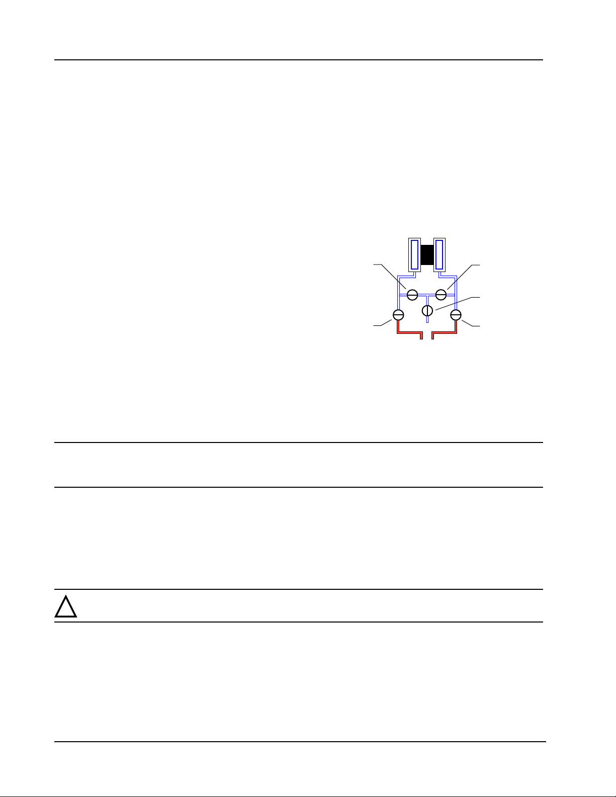
Section 2 Scanner® 2000 microEFM
5. Monitor the pressure readout and watch for a steady decrease in pressure. If leakage is indicated, depressurize the system by opening both bypass/block valves, then check all manifold and piping joints. Tighten
connections as necessary.
6. Repeat steps 3 through 5 to retest the manifold for leaks.
An additional test can verify the condition of the equalizing valves. Assuming the above test has conrmed
the system is leak free, close both equalizing valves and open the vent. Monitor the differential pressure
reading for any change. Repair or replace the manifold as required if the differential pressure varies.
Zero Offset (Static Pressure or Differential Pressure)
The static pressure input for the Scanner 2000 is zeroed at the factory before shipment. However, changes
in temperature and atmospheric pressure can cause the
static pressure and differential pressure readings to vary.
The inputs can be easily zeroed in the eld, if necessary,
prior to putting the Scanner 2000 into service.
EQUALIZER
EQUALIZER
To zero the static pressure or differential pressure
VENT
1. Close the bypass valves to isolate the pressure below
the manifold.
BYPASS/
BLOCK
BYPASS/
BLOCK
2. Open the equalizer and vent valves.
3. Connect to the Scanner 2000 with the ModWorX™ Pro software, and apply zero pressure from the Cali-
brate Inputs screen (see the ModWorX™ Pro Software User Manual; Part No. 9A-30165025; for
complete instructions).
Static Pressure Calibration and Verication
Note The pressure range stamped on the MVT is expressed as psia (absolute). However, Scanner 2000
pressure inputs are recalibrated as psig (gauge) at the factory before the device is shipped. Therefore, pressure readings displayed on the LCD and in the ModWorX Pro software are in terms of psig.
The static pressure and differential pressure inputs are calibrated and veried before the Scanner 2000 leaves
the factory, and recalibration in the eld may or may not be required. To comply with API standards for
verication, “as found” readings should be recorded at approximately 0, 50, and 100 percent of the operating
pressure range, increasing, and at 80, 20 and 0 percent of the operating pressure range, decreasing. For
example, the static pressure measurements of a 1500-psi sensor should be veried at 0 psi, 750 psi, and 1500
psi, then at 1200 psi, 300 psi, and 0 psi.
WARNING: Do not subject the Scanner 2000 microEFM to unnecessary shock or over-range
!
pressure during maintenance operations.
To calibrate the static pressure
1. Close the bypass valves to isolate the pressure below the manifold.
2. Open the equalizer valves and vent valve to purge the lines.
3. Close the vent valve.
4. Connect a static pressure simulator to the manifold (either side).
56
Page 57
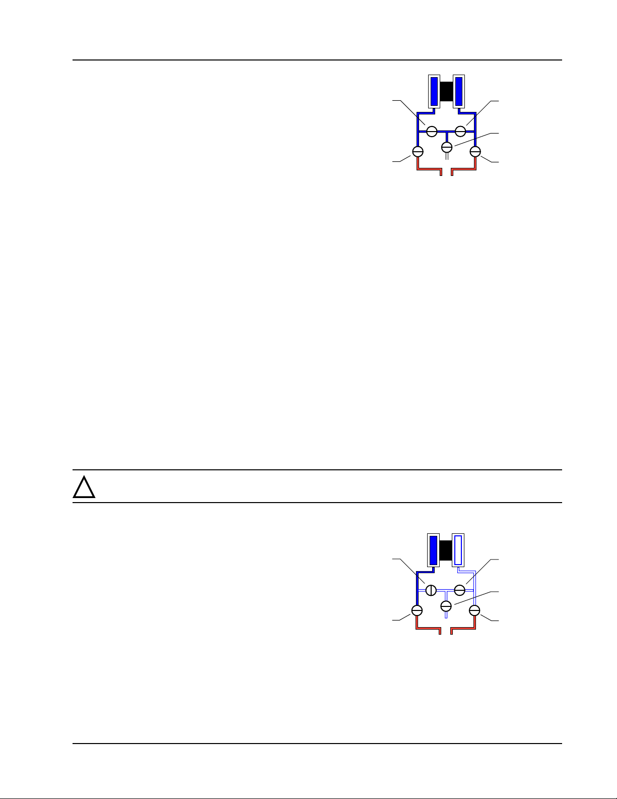
Scanner® 2000 microEFM Section 2
5. Connect to the Scanner 2000 with the ModWorX™
Pro software. Click on the Calibrate Inputs menu
button and proceed through the calibration per
EQUALIZER
EQUALIZER
instructions in the ModWorX™ Pro Software User
Manual.
VENT
6. At the appropriate software prompt, enter a known
pressure.
BYPASS/
BLOCK
BYPASS/
BLOCK
7. Apply the same amount of pressure to the MVT us-
ing the simulator (see the ModWorX™ Pro Software User Manual for complete instructions). The ModWorX™ Pro software will display a measured value and a percentage of change.
8. Repeat steps 6 and 7 as necessary to enter multiple calibration points.
9. When all calibration points have been entered, click Save Changes to apply the new calibration settings.
To verify the static pressure, perform the steps described in the calibration procedure above, except instead
of choosing Calibrate from the Change Calibration Task window, choose Verify. You will be prompted to
enter an applied value, and you will apply the same amount of pressure to the MVT, just as in the calibration
process. The ModWorX™ Pro software will display a measured value and a percentage of error. When you
click Save Changes, the measured values are written to memory for reference.
Differential Pressure Calibration and Verication
The static pressure and differential pressure inputs are calibrated and veried before the Scanner 2000 leaves
the factory, and recalibration in the eld may or may not be required. To comply with API standards for
verication, “as found” readings should be recorded at approximately 0, 50, and 100 percent of the operating
pressure range, increasing, and at 80, 20 and 0 percent of the operating pressure range, decreasing. For
example, the differential pressure measurements of a 200-In. H2O sensor should be veried at 0 In. H2O, 100
In. H2O, 200 In. H2O, then at 160 In. H2O, 40 In. H2O, and 0 In. H2O.
WARNING: Do not subject the Scanner 2000 microEFM to unnecessary shock or over-range
!
pressure during maintenance operations.
To calibrate the differential pressure
1. Close the bypass valves to isolate the pressure below
the manifold.
EQUALIZER
EQUALIZER
2. Open the equalizer valves and vent valve to purge
the lines.
VENT
3. Close the high-pressure side equalizer valve.
4. Connect a pressure simulator to the high-pressure
BYPASS/
BLOCK
BYPASS/
BLOCK
side of the manifold.
5. Connect to the Scanner 2000 with the ModWorX™ Pro software. Click on the Calibrate Inputs menu
button and proceed through the calibration per instructions in the ModWorX™ Pro Software User Manual, Part No. 9A-30165025.
6. At the appropriate software prompt, enter a known pressure.
57
Page 58
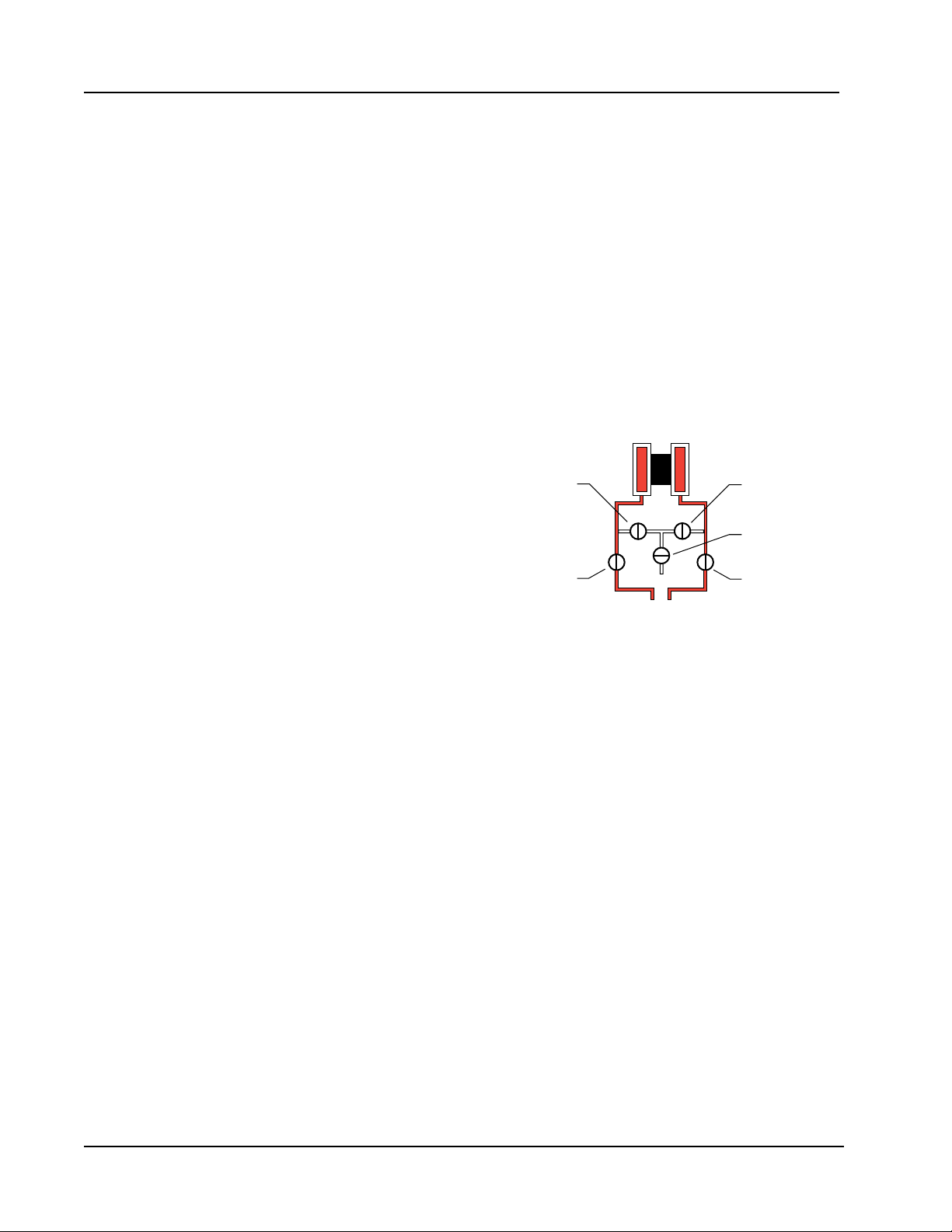
Section 2 Scanner® 2000 microEFM
7. Apply the same amount of pressure to the high side of the MVT using the simulator (see the ModWorX™
Pro Software User Manual, Part No. 9A-30165025, for complete instructions). The ModWorX™ Pro
software will display a measured value.
8. Repeat steps 6 and 7 as necessary, to enter multiple calibration points, and apply the new measured values
from the ModWorX™ Pro interface.
9. When all calibration points have been entered, click Save Changes to apply the new calibration settings.
To verify the differential pressure, perform the steps described in the calibration procedure above, except
instead of choosing Calibrate from the Change Calibration Task window, choose Verify. You will be
prompted to enter an applied value, and you will apply the same amount of pressure to the MVT, just as in the
calibration process. The ModWorX™ Pro software will display a measured value and a percentage of error.
When you click Save Changes, the measured values are written to memory for reference.
Placing the Scanner into Operation
To put the Scanner into operation;
1. Close the vent valve.
EQUALIZER
EQUALIZER
2. Open the equalizer valves.
3. Open the bypass/block valves to allow pressure to be
VENT
supplied to both sides of the MVT.
4. Close the equalizer valves.
BYPASS/
BLOCK
BYPASS/
BLOCK
5. Open the vent valve (optional, some users may
choose to leave the vent closed).
Industry Standard Compliance
To ensure measurement accuracy, ow runs and turbine meter runs must be installed in accordance with
industry standards. Table 2.2, page 59, and Table 2.3, page 60, reference the sections in these standards that apply
specically to ow run and hardware installation.
Table 2.4, page 60, references standards that apply to uid properties for gas, steam, and liquid measurement.
Fluid properties used for gas measurement calculations such as compressibility factors and density are in
accordance with AGA Report No. 8. For steam measurement, algorithms are based on the IAPWS IndustrialFormulation 1997 (IF-97) standard. For temperature-compensated liquid measurement, uid property
calculations are based on API-2540 - 1980, Petroleum Measurement Tables.
Heating values for gas measurement are calculated in accordance with AGA Report No. 3, Part 3, Appendix F,
using the constants dened in GPA 2145.
For more information, see the ModWorX™ Pro Software User Manual, Part No. 9A-30165025.
58
Page 59

Scanner® 2000 microEFM Section 2
Table 2.2—Industry Standards for Orice Meters
Standard Applicable Section Description Notes
AGA Report No. 3:
Orice Metering of
Natural Gas and Other
Related Hydrocarbon
Fluids
ISO 5167:
Measurement of Fluid
Flow by Means of
Pressure Differential
Devices Inserted in
Circular Cross-Section
Conduits Running Full
ISO 5167:
Measurement of Fluid
Flow by Means of
Pressure Differential
Devices Inserted in
Circular Cross-Section
Conduits Running Full
API Manual
of Petroleum
Measurement
Standards, Chapter
21.1 (Electronic Gas
Measurement)
Part 2: Specication
and Installation
Requirements,
Section 2.6
(Installation
requirements)
Part 1: General
Principles and
Requirements
Part 2: Orice
Plates
Section 1.7
-Equipment
Installation
Section 1.8
-Equipment
Calibration and
Verication
Specications for orice
meters (to include beta ratios)
Installation requirements for
orice plates, meter tubes, ow
conditioners, and thermometer
wells
Installation of orice plates
inserted into a circular crosssection conduit running full
Limitation of pipe size and
Reynolds number
Species orice plates that can
be used with ange pressure
tappings, corner pressure
tappings, D and D/2 pressure
tappings.
Installation of electronic gas
measurement devices and
associated communications,
gauge/impulse lines, and
cabling
Requirements for calibrating
and verifying the accuracy of
electronic gas measurement
devices
This standard is also
distributed under the
following names: API
MPMS Chapter 14.3, Part
2; ANSI/API 14.3, Part
2-2000; and GPA 8185,
Part 2.
ISO 5167 is applicable
only to ow that remains
subsonic throughout the
measuring section and
where the uid can be
considered single-phase.
It is not applicable to the
measurement of pulsating
ow. It does not cover the
use of orice plates in pipe
sizes less than 50 mm
(2 in.) or more than 1000
mm (39 in.), or for pipe
Reynolds numbers below
5000.
Industry Standards for Cone Meters
For installation requirements for use with a cone meter and applicable ow rate calculations, see the NuFlo
Cone Meter User Manual, Part No. 9A-85165000.
59
Page 60

Section 2 Scanner® 2000 microEFM
Table 2.3—Industry Standards for Turbine Meters
Standard Applicable Section Description Notes
AGA Report No. 7:
Measurement of
Natural Gas by Turbine
Meters
API Manual
of Petroleum
Measurement
Standards, Chapter
21.1 (Electronic Gas
Measurement)
API Manual
of Petroleum
Measurement
Standards, Chapter 5
(Metering)
Section 7Installation
Specications
Section 1.7
-Equipment
Installation
Section 1.8
-Equipment
Calibration and
Verication
Section 3,
Measurement
of Liquid
Hydrocarbons by
Turbine Meters
Installation of gas turbine
meters to include ow
direction, meter orientation,
meter run connections, internal
surfaces, temperature well
location, pressure tap location,
and ow conditioning
Illustrations of recommended
installation congurations
Environmental considerations,
the use of other devices to
improve meter performance,
and precautionary measures.
Installation of electronic gas
measurement devices and
associated communications,
gauge/impulse lines, and
cabling
Requirements for calibrating
and verifying the accuracy of
electronic gas measurement
devices
Description of unique
installation requirements and
performance characteristics
of turbine meters in liquid
hydrocarbon service
This specication
applies to axial-ow
turbine owmeters for
measurement of natural
gas, typically 2-in. and
larger bore diameter, in
which the entire gas stream
ows through the meter
rotor.
This section does not apply
to the measurement of twophase uids.
Table 2.4—Industry Standards for Fluid Properties
AGA Report No. 3, “Orice Metering of Natural Gas and Other Related Hydrocarbon Fluids,” Part 3, “Natural
Gas Applications,” Third Edition, 1992, Appendix F, “Heating Value Calculation,” American Gas Association,
catalog XQ9210.
GPA 2145-09, “Table of Physical Properties for Hydrocarbons and Other Compounds of Interest to the
Natural Gas Industry,” Gas Processors Association, Tulsa Oklahoma, 2008.
AGA Report No 8, “Compressibility Factors of Natural Gas and Other Related Hydrocarbon Gases,” Second
Edition, AGA Catalogue XQ9212, American Gas Association, Arlington Virginia 1994.
W. Wagner and A. Kruse, “Properties of Water and Steam - The Industrial Standard IAPWS-IF97 for the
Thermodynamic Properties and Supplementary Equations for Other Properties,” Springer-Verlag, Berlin
Heidelburg 1998, ISBN 3-540-64339-7.
API-2540, “Petroleum Measurement Tables,” American Petroleum Institute, 1980.
60
Page 61

Scanner® 2000 microEFM Section 3
Section 3—Wiring the Scanner 2000
Field Wiring Connections
WARNING: Do not connect/disconnect equipment or change batteries unless the area is known
!
to be non-hazardous. The Scanner 2000 poses no hazard when opened in a safe area.
CAUTION All eld wiring must conform to the National Electrical Code, NFPA 70, Article 501-4(b)
for installations within the United States or the Canadian Electric Code for installations
within Canada. Local wiring ordinances may also apply. All eld wiring must be rated for
temperatures of 90°C or higher, and have a wire range of 22 to 14 AWG. Terminal block
screws must be tightened to a minimum torque of 5 to 7 in-lbs. to secure the wiring
within the terminal block. Only personnel who are experienced with eld wiring should
perform these procedures.
To wire the Scanner 2000 for operation, complete the following eld connections:
1. Unscrew the cover of the enclosure counter-clockwise until it separates from the main body of the enclo-
sure.
2. Using a small standard blade screwdriver, remove the two #4-40 × 7/8” screws located to the right and
left side of the display.
3. Lift the display/keypad assembly from the enclosure, making sure the circuit assembly does not contact
the enclosure.
4. Connect the lithium battery to the J1 connector on the circuit assembly. See Figure 3.2, page 63.
5. Connect wiring for external power, if appropriate. See Grounding Procedures, page 62, and see Figure 3.3,
page 64 for a wiring diagram.
6. Connect the owmeter input wiring to terminal block TB2, if appropriate. See Figure 3.4, page 65.
7. Connect the process temperature input wiring to terminal block TB2, if appropriate. See Figure 3.5, page
66.
8. Connect wiring for output signals, if appropriate. See Figure 3.6, page 67, Figure 3.7, page 68, and Figure
3.8, page 69. If the instrument is equipped with an expansion board, connect wiring for expansion board
inputs/outputs, if appropriate. See page A-10 for expansion board wiring diagrams.
9. Place the circuit assembly over the standoffs and fasten with the two #4-40 × 7/8” screws, ensuring that
all connector wiring is inside the enclosure and in no position where it may be damaged when the enclo-
sure cover is replaced.
10. Recalibrate the Scanner 2000 (if necessary).
11. If external and internal power supplies were removed, reset the clock to ensure that the time stamps in the
log data are accurate. The clock can be reset using the instrument keypad or ModWorX™ Pro software.
12. Replace the enclosure cover by threading it onto the enclosure in a clockwise direction.
61
Page 62
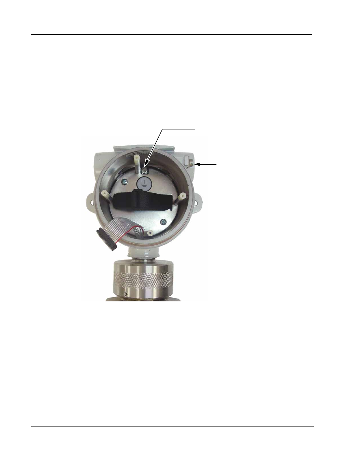
Section 3 Scanner® 2000 microEFM
Grounding Procedures
To power the Scanner 2000 microEFM with an external DC supply, route the ground conductor through a
conduit opening in the top of the Scanner 2000 enclosure with the power conductors and connect it to the
ground screw inside the enclosure (note the round sticker that marks this location in Figure 3.1).
If national or local electrical codes require the enclosure to be grounded, a protective earth grounding
conductor may be required. To install a protective earth ground, connect an earth ground conductor to the
stainless ground lug near the top of the Scanner 2000 enclosure (also shown in Figure 3.1) or to the internal
ground screw, and connect the other end to a ground rod or other suitable system earth ground. The ground
lugs will accept wire sizes from 14 AWG solid conductor to 4 AWG stranded conductor.
Internal
ground screw
External
ground screw
Figure 3.1—Ground screw locations
62
Page 63
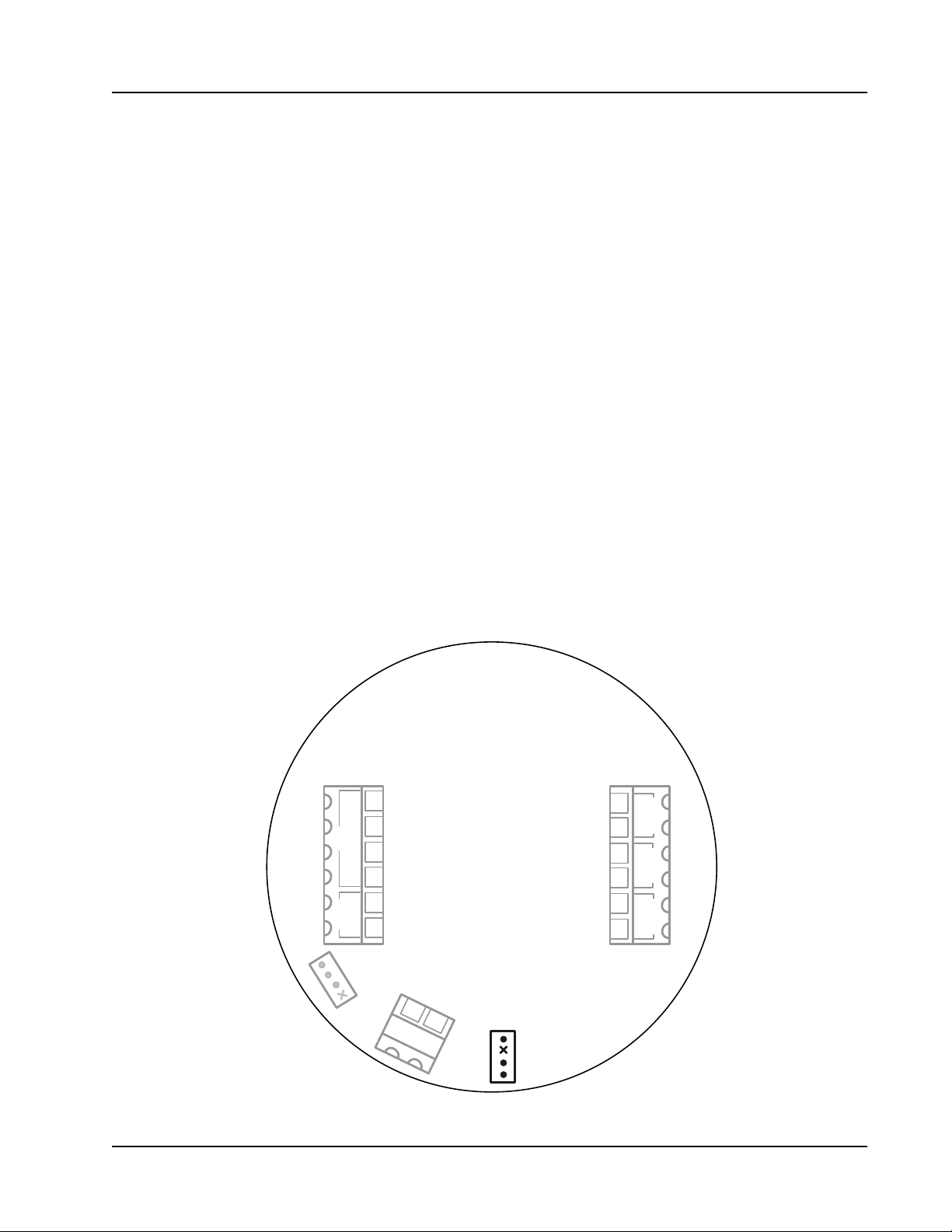
Scanner® 2000 microEFM Section 3
Power Supply Wiring
Internal Power Supply
The Scanner 2000 microEFM is shipped with a lithium battery pack. To supply power to the instrument,
connect the battery cable to connector J1 on the main circuit assembly (Figure 3.2).
Low-power microprocessor technology enables the Scanner 2000 to operate for an estimated 1 year on a
lithium battery pack. The lithium battery pack is ideal for use in extreme temperatures, although extreme cold
temperatures may reduce battery life.
To maximize battery life,
• operate the Scanner using the following default conguration settings:
– calculation frequency: 1 minute
– logging frequency (interval): 1 hour
– download frequency: monthly
• disconnect the Scanner 2000 from the RS-232 to RS-485 converter when ModWorX Pro software is not
in use. When ModWorX Pro is running, the computer powers the converter; when the software is not running, the Scanner 2000 powers the converter, causing a current drain to the Scanner battery.
• avoid the following conditions/activities:
– operation at extremely cold temperatures
– use of digital output (pulse or alarm)
– use of analog input without external power (when expansion board is installed)
POWER
+
7
–
8
+
PORT 2 P ORT 1
9
–
10
+
11
–
12
J2
-
1
2
3
4
5
6
I
-
R
RTD
+
R
+
I
SCANNER 2000
Main Circuit Board
PN: 9A-30160010
–
+
TFM 1
TB1 TB2
13
SWITCH
DIG OUT 1
14
BATTERY
Figure 3.2—Lithium battery pack connection
TB3
J1
63
Page 64
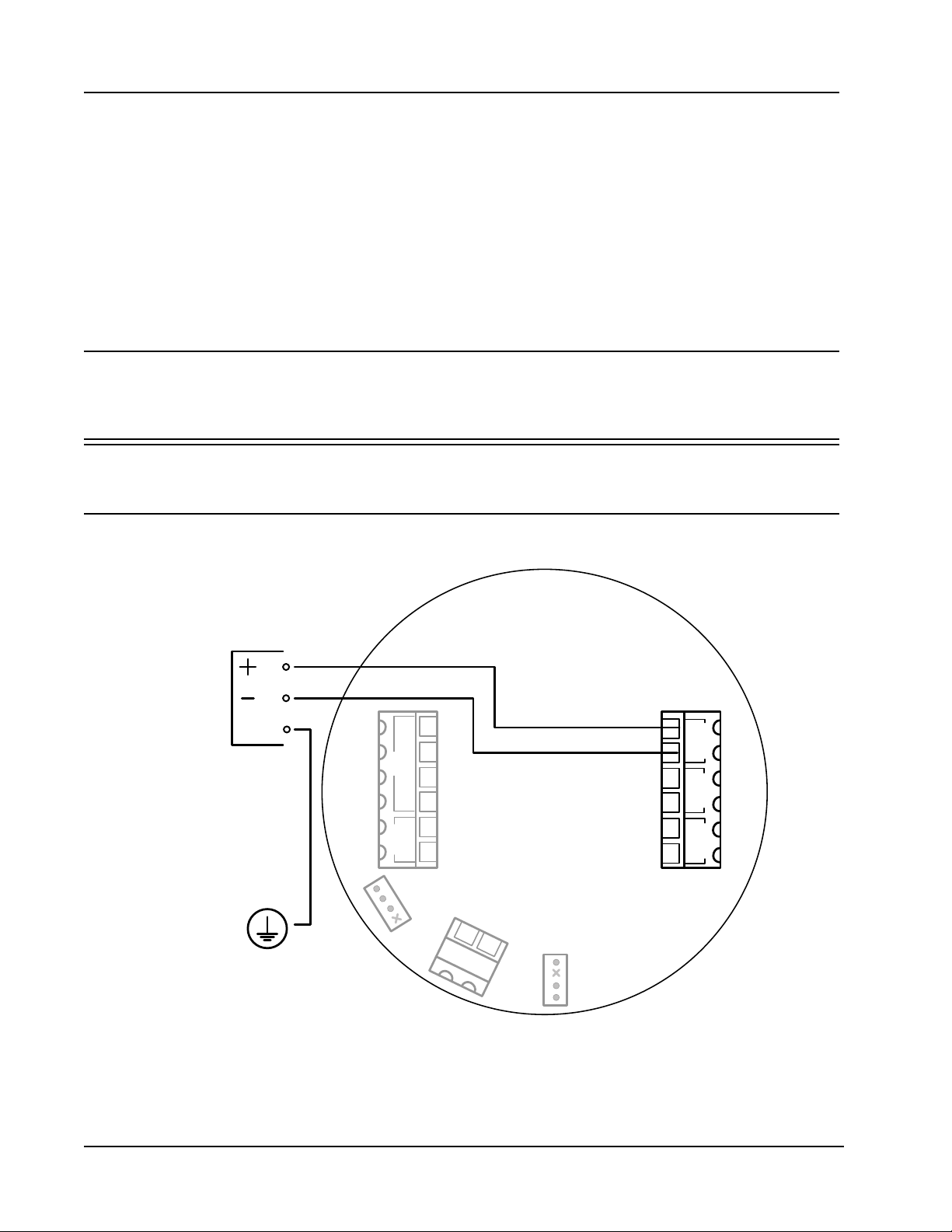
Section 3 Scanner® 2000 microEFM
When an external power supply is used as the primary power source, the lithium battery pack serves as
a backup power supply. The use of an alternate power source extends battery life and helps ensure that
timekeeping and volume accumulation will not be interrupted during a power failure.
External Power Supply
The Scanner 2000 can be connected to a remote power supply by a two-conductor cable (Figure 3.3). The
power supply and cable must be capable of supplying 6 to 30 VDC @ 50 mA.
The external power supply must be an approved SELV source, insulated from the AC main by double/
reinforced insulation per CSA C22.2 No.61010-1-04 / UL 61010-1 – 2nd Edition.
Important In all applications using an external power supply, a switch or circuit breaker must be in-
cluded in the safe area external power supply installation within easy reach of the operator. The switch or circuit breaker must be marked as the “disconnect” for the safe area
external DC power supply.
Important If the main circuit board is marked with a revision level of 02 or older (revisions 01, C, B,
or A), a zener diode (Part No. 1.5KE33CA) must be installed for CE approval. The zener
diode is not required for revision 03 and newer circuit boards.
POWER
SUPPLY
6 to 30
VDC
GND
GROUND
SCREW INSIDE
ENCLOSURE
Figure 3.3—External power supply wiring
J2
POWER
-
1
2
3
4
5
6
I
-
R
RTD
+
R
+
I
–
+
TFM 1
TB1 TB2
SWITCH
SCANNER 2000
Main Circuit Board
PN: 9A-30160010
13
14
DIG OUT 1
TB3
BATTERY
J1
+
7
–
8
+
PORT 2
9
–
10
PORT 1
+
11
–
12
64
Page 65
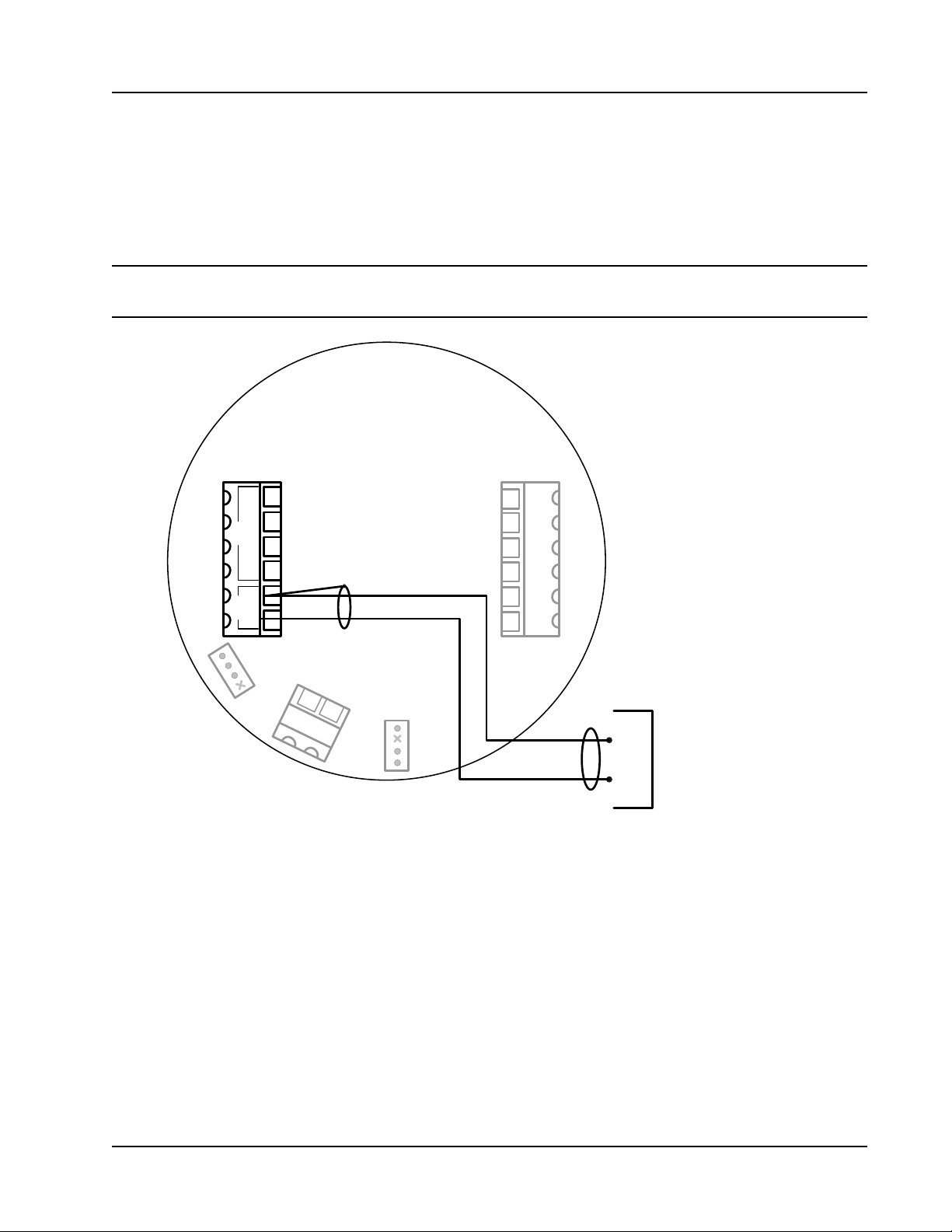
Scanner® 2000 microEFM Section 3
Input Wiring
Turbine Flowmeter Input
The Turbine Input 1 on the main circuit board provides the turbine owmeter input signal generated
by a magnetic pickup, enabling the Scanner 2000 to calculate and display instantaneous ow rates and
accumulated totals. Wire as shown in Figure 3.4.
Note If the expansion board option is installed, a second turbine input is available. See Figure A.17, page A-12,
for Turbine Input 2 wiring instructions.
SCANNER 2000
Main Circuit Board
PN: 9A-30160010
+
POWER
7
–
8
+
PORT 2 PORT 1
9
–
10
+
11
–
12
J2
-
1
I
-
2
R
+
R
3
+
I
4
–
5
+
TFM 1 RTD
6
TB1 TB2
13
SWITCH
DIG OUT 1
14
TB3
Figure 3.4—Flowmeter input wiring
BATTERY
J1
B
TURBINE
MAGNETIC PICKUP
A
65
Page 66
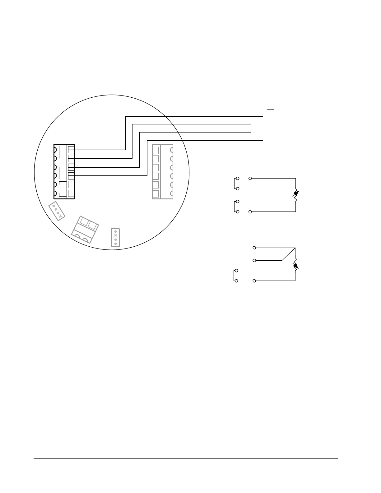
Section 3 Scanner® 2000 microEFM
RTD Input
The RTDs described in Appendix A of this manual are recommended for measuring temperature for use
in temperature-compensated gas and liquid calculations, though a 2- or 3-wire RTD may prove functional.
Wiring is essentially the same for all three models, though wire color may vary as indicated. Wire as shown in
Figure 3.5.
-
I
1
-
R
2
+
R
3
+
I
4
–
5
+
TFM 1 RTD
6
J2
TB1
SWITCH
SCANNER 2000
Main Circuit Board
PN: 30160010
13
14
DIG OUT 1
TB3
TB2
BATTERY
J1
Figure 3.5—Process temperature input wiring
WHITE
WHITE
RED OR BLACK
RED OR BLACK
POWER
+
7
–
8
+
PORT 2 PORT 1
9
–
10
+
11
–
12
JUMPER
WIRE
JUMPER
WIRE
2 - WIRE
I-
RTD -
RTD+
I+
I
RTD-
RTD+
RED OR BLACK
RTD CONNECTIONS
RECOMMENDED)
I
WHITE
(4-WIRE
3 - WIRE
WHITE
WHITE
RED OR BLACK
JUMPER
WIRE
I-
RTD -
RTD+
I+
66
Page 67
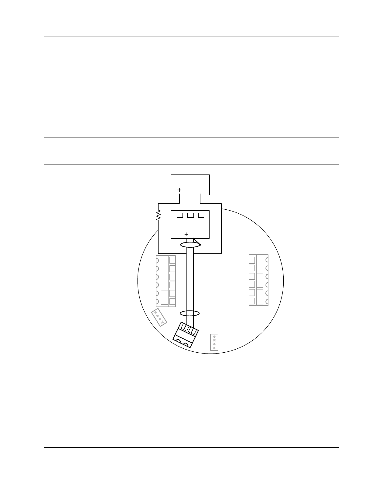
Scanner® 2000 microEFM Section 3
Output Wiring
Digital Output (Pulse or Alarm)
The standard Scanner 2000 supports a solid-state digital output that is congurable as either a pulse output or
an alarm output. As a pulse output, the pulse width duration and pulse representation are both congurable.
Because the circuit is isolated, it can be used in conjunction with any other feature on the Scanner 2000. A
two-conductor cable from the Scanner 2000 to the remote location is required. The maximum rating of the
digital output circuit is 60 mA at 30 VDC. Maximum frequency is 50 Hz. Wire as shown in Figure 3.6.
For reduced power consumption, turn the digital output feature off when it is not in use.
Important If the main circuit board is marked with a revision level of 02 or older (revision 01, C, B,
or A), a zener diode (Part No. IN4752) must be installed for CE approval. The zener diode
is not required for revision 03 and newer circuit boards.
POWER SUPPLY
5 to 30 VDC
Resistor may be included
in pulse readout device.
Size the resistor to limit
the current to 60 mA.
PULSE READOUT
DEVICE
Figure 3.6—Pulse output wiring
+
TB2
POWER
7
–
8
+
PORT 2
9
–
10
+
PORT 1
11
–
12
-
I
1
-
R
2
+
R
3
+
I
4
–
5
+
TFM 1 RTD
6
J2
SWITCH
TB1
DIG OUT 1
SCANNER 2000
Main Circuit Board
PN: 9A-30160010
Leave the end of this
shield disconnected.
13
14
BATTERY
TB3
J1
67
Page 68
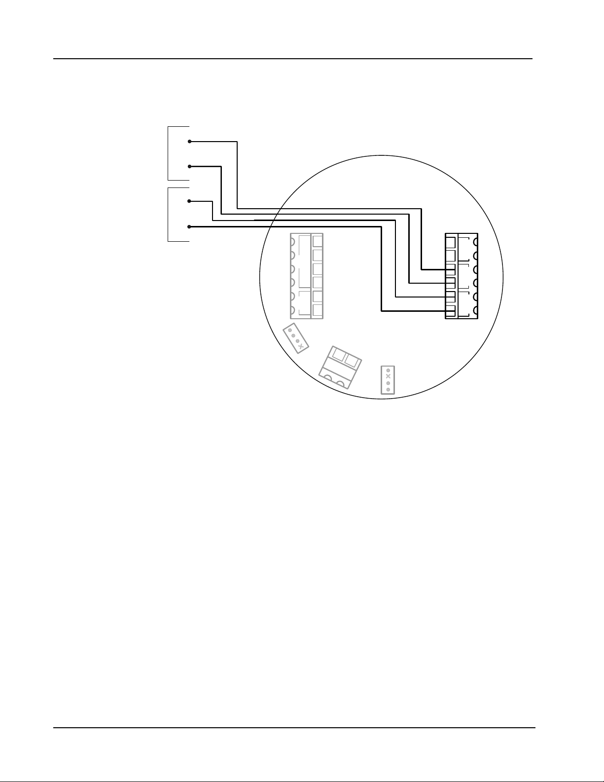
Section 3 Scanner® 2000 microEFM
RS-485 Output—Permanent Computer Connection
The RS-485 output is required for communication with the interface software. The wiring diagram in Figure
3.7 supports a permanent connection.
PORT 2 RS-485
COMMUNICATIONS
+
–
PORT 1 RS-485
COMMUNICATIONS
+
–
Figure 3.7—RS-485 output (permanent connection)
SCANNER 2000
Main Circuit Board
PN: 9A-30160010
+
-
I
1 7
-
2
R+ R
3
I+
4
–
5
+
TFM 1 RTD
6
J2
TB1 TB2
13
SWITCH
DIG OUT 1
14
BATTERY
TB3
J1
POWER
–
+
PORT 2 PORT 1
–
+
–
8
9
10
11
12
68
Page 69
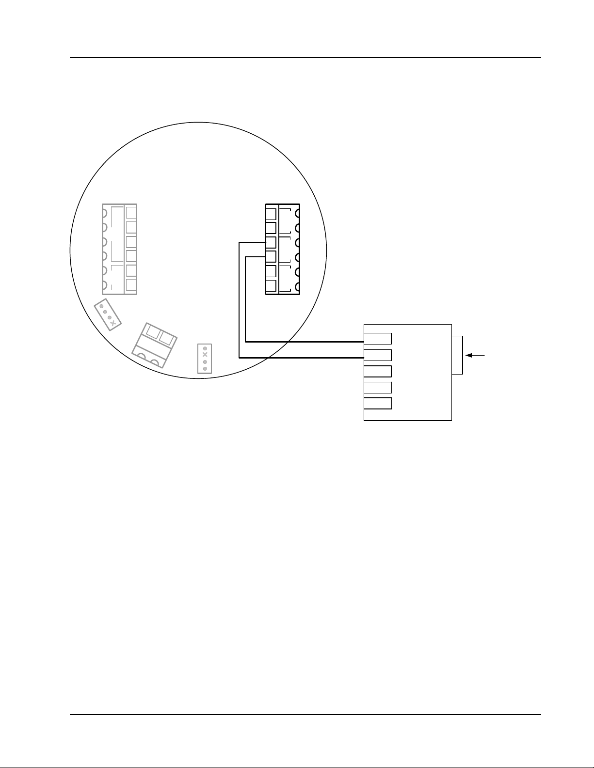
Scanner® 2000 microEFM Section 3
RS-485 Output—Laptop Computer Connection
The RS-485 output is required for communication with the interface software. The wiring diagram in Figure
3.8 supports a temporary laptop connections using an RS-232 to RS-485 converter.
POWER
-
I
1
-
R
2
+
R
3
+
I
4
–
5
+
TFM 1 RTD
6
J2
TB1 TB2
SWITCH
SCANNER 2000
Main Circuit Board
PN: 9A-30160010
13
14
DIG OUT 1
TB3
BATTERY
J1
+
7
–
8
+
PORT 2 PORT 1
9
–
10
+
11
–
12
PORT 2 CONNECTIONS ARE
SHOWN IN THIS DIAGRAM.
TO USE PORT 1:
CONNECT TD(B) TO TERMINAL 11 (+).
CONNECT TD(A) TO TERMINAL 12 (-).
TX-
TX+
TD(A)
TD(B)
GND
GND
+12V
RS-232
9 - PIN
CONNECTOR
Figure 3.8—RS-485 output (connection to laptop with 9-pin converter)
Part No . 9A-101283116
69
Page 70

Section 3 Scanner® 2000 microEFM
Conguration via Keypad
Communication parameters such as slave address and baud rate, the date and time, contract hour and plate
size can all be congured via the three-button keypad on the front of the instrument. See Section 4—
Conguration and Operation via Keypad for step-by-step instructions. All other instrument calibration is
performed via the ModWorX™ Pro software.
WARNING: To prevent ignition of hazardous atmospheres, do not remove the cover while cir-
!
cuits are alive. The Scanner 2000 poses no hazard when opened in a safe area.
Conguration via ModWorX™ Pro Software
A laptop connection and the ModWorX™ Pro software provided with the Scanner 2000 are required for
the calibration and conguration of the instrument. The Scanner 2000’s natural gas and steam calculations
typically require conguration of inputs including differential pressure, static pressure, process temperature,
and for AGA-7, a turbine meter input.
The Scanner 2000 microEFM supports digital serial communications using EIA-RS-485 hardware with
Modicon Modbus® protocol. Either of two Modbus® slave ports facilitates communications with a laptop or
PC. The baud rate range for both ports is 300 to 38.4K. Both ports are protected from high-voltage transients.
IMPORTANT: The Scanner 2000 for Foundation™ eldbus has a single port for communications.
An RS-232 to RS-485 converter or NuFlo USB adapter is required for connecting the microEFM to a laptop
or PC. The converters available from Cameron require no handshaking or external power to operate. See
Section 6—Spare Parts for ordering information; see Figure 3.7, page 68, and Figure 3.8, page 69, for wiring
instructions.
The NuFlo USB adapter provides an external USB port for connecting to a laptop, and is available as a kit for
upgrading a Scanner 2000. See USB Communications Adapter (CSA Div. 1 or Div. 2), page A-6 for details;
see Section 6—Spare Parts for ordering information.
WARNING: To prevent ignition of hazardous atmospheres, do not remove the Scanner 2000
!
cover while circuits are alive. The Scanner 2000 poses no hazard when opened in a safe area.
70
Page 71
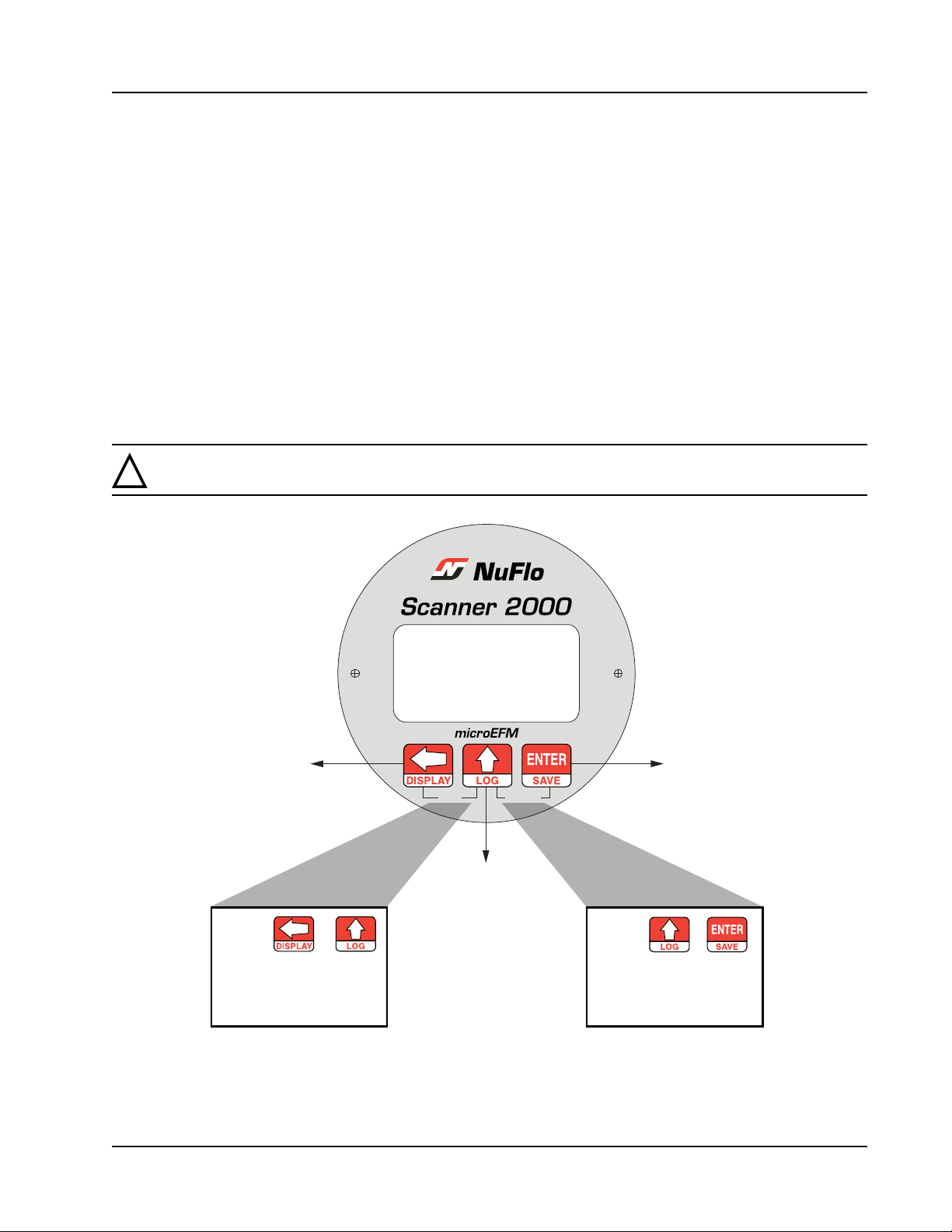
Scanner® 2000 microEFM Section 4
Section 4—Conguration and Operation via Keypad
The following parameters can be congured using the three-button keypad on the front of the instrument, as
shown in Figure 4.1:
• slave address
• baud rate
• date and time
• contract hour
• plate size
All other instrument conguration is performed via the ModWorX™ Pro software.
Because the keypad is protected beneath the lid of the instrument, the enclosure must be opened to access the
keypad. For this reason, it is important to congure these settings before installing it in a hazardous area.
WARNING: To prevent ignition of hazardous atmospheres, do not remove the cover while cir-
!
cuits are alive. The Scanner 2000 microEFM poses no hazard when opened in a safe area.
CONFIGURATION:
Move between menus
and menu selections
OPERATION:
View next parameter
PRESS +
simultaneously to view
time/date, temperature,
and battery voltage
Figure 4.1—Scanner 2000 keypad operation and calibration functions
TEST ACCESS
CONFIGURATION:
Change digits and
other menu selections
OPERATION:
View daily logs
CONFIGURATION:
Save configuration
settings
OPERATION:
Save totals
PRESS +
simultaneously to access
Configuration menu
71
Page 72
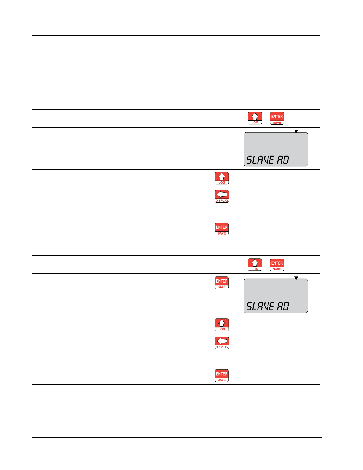
Section 4 Scanner® 2000 microEFM
Entering the Slave Address
The slave address is a setting used in Modbus® communications. It is a number that ranges from 1 to 65535,
excluding 252 to 255 and 64764, which are reserved. If the Modbus
®
request message contains the matching
address, the device will respond to the request. In network arrangements, the device must have a unique slave
®
address. For more information about Modbus
communications, refer to Section 1—Introduction. If Modbus®
communications are not used, leave the slave address at the factory setting (1).
To Enter a Port 1 Slave Address:
Enter the Access menu. Press UP ARROW and ENTER
simultaneously.
Locate the Slave Address setting. PORT 1 SLAVE ADDRESS will
appear in the lower display, and the
rightmost digit in the top display will
begin blinking.
+
00000000
...
Enter the Slave Address.
(range: 1 to 6553
255 and 64764)
5; excluding 252 to
Press UP ARROW until the correct
digit is displayed.
Then press LEFT ARROW to select
the next digit to the left.
Repeat using UP and LEFT arrows to
enter all remaining digits.
Press ENTER.
To Enter a Port 2 Slave Address:
Enter the Access menu. Press UP ARROW and ENTER
simultaneously.
Locate the Slave Address setting. Press ENTER twice until PORT 2
SLAVE ADDRESS appears in the
lower display. The rightmost digit in
the top display will begin blinking.
+
00000000
...
Enter the Slave Address.
(range: 1 to 6553
255 and 64764)
5; excluding 252 to
The Baud Rate menu prompt will appear immediately following the entry of the slave address. See Entering
theBaudRate below for the baud rate entry procedure.
Press UP ARROW until the correct
digit is displayed.
Then press LEFT ARROW to select
the next digit to the left.
Repeat using UP and LEFT arrows to
enter all remaining digits.
Press ENTER.
72
Page 73
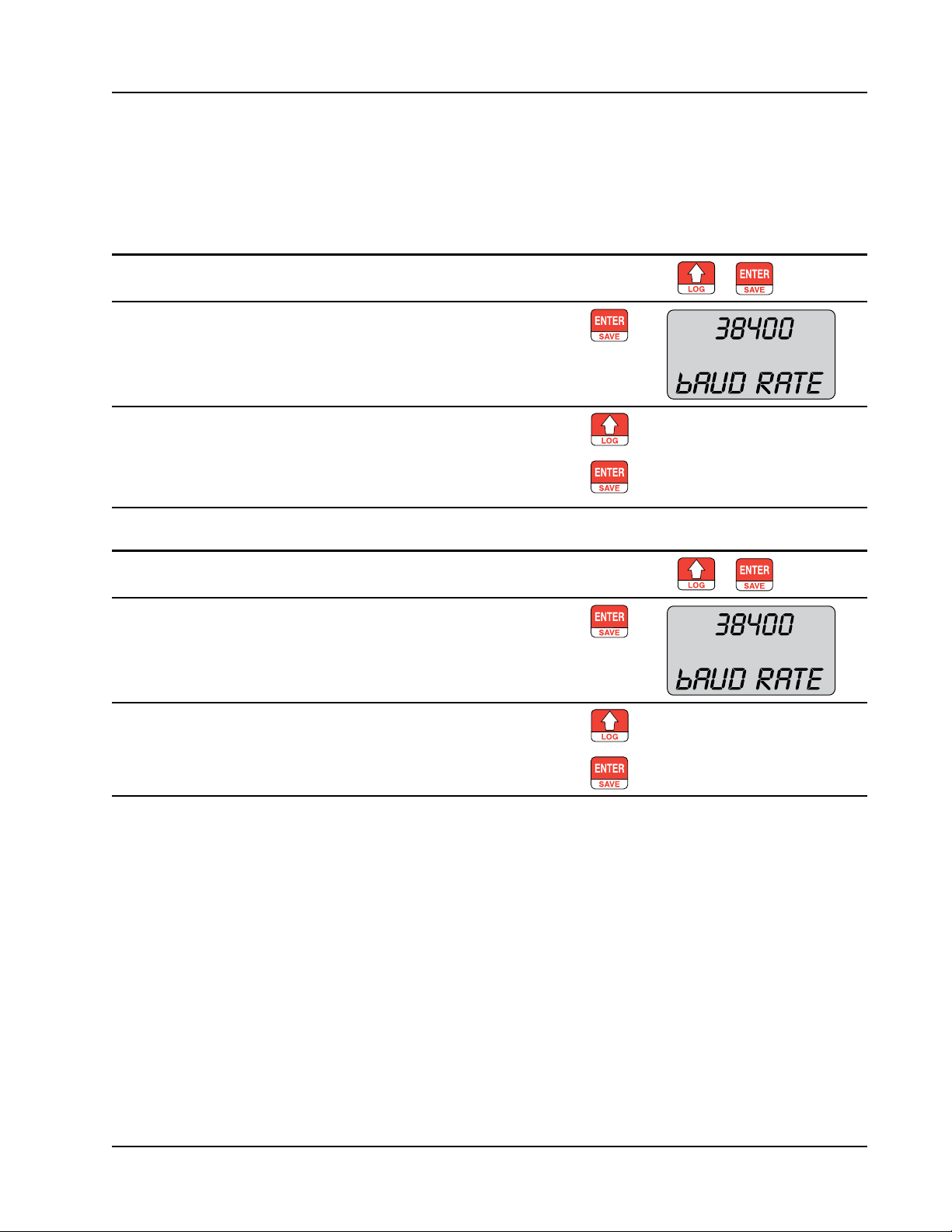
Scanner® 2000 microEFM Section 4
Entering the Baud Rate
The baud rate is the number of bits per second that are on the serial port. This setting must match the setting
of the master device polling the Scanner 2000 or the serial port. This only applies to the Modbus
®
cations; if Modbus
communications are not used, leave the baud rate at the factory setting (9600).
®
communi-
To Enter the Port 1 Baud Rate:
Enter the Access menu. Press UP ARROW and ENTER
simultaneously.
Locate the Baud Rate setting. Press ENTER. The words “PORT 1
BAUD RATE” will appear in the lower
display.
Enter the baud rate. Press UP ARROW until the correct
baud rate is displayed.
Press ENTER. ”PORT 2 SLAVE
ADDRESS” will appear in the bottom
display.
+
To Enter the Port 2 Baud Rate:
Enter the Access menu. Press UP ARROW and ENTER
simultaneously.
Locate the Baud Rate setting. Press ENTER three times. The
words “PORT 2 BAUD RATE” will
appear in the lower display.
+
Enter the baud rate. Press UP ARROW until the desired
baud rate is displayed.
Press ENTER. ”EDIT DATE-TIME”
will appear in the bottom display.
73
Page 74
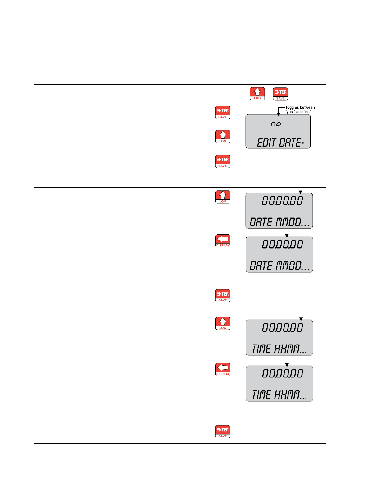
Section 4 Scanner® 2000 microEFM
Editing the Date and Time
A user can change the date and time from the keypad.
To Edit the Date and Time:
Enter the Access menu. Press UP ARROW and ENTER
simultaneously.
Locate the Date and Time setting. Press ENTER four times. The words
“EDIT DATE-TIME” will appear in
the lower display and the word “no”
or “yes” will begin ashing in the top
display (default is “no”).
+
Enter the month, day and year.
The format is MM.DD.YY.
Enter the time (hour, minute, and
seconds). The format is HH.MM.SS.
Press the UP ARROW to change the
setting in the top display to “YES.”
Press ENTER. “DATE MMDDYY” will
appear in the bottom display, and the
last two digits, representing the year,
will begin ashing.
To change the year, press the UP
ARROW, repeatedly if necessary,
until the last two digits of the year
are displayed (for example, for 2006,
enter “06”).
To change the day, press the LEFT
ARROW. The two middle digits will
begin ashing. Press the UP arrow
until the correct day is displayed.
Repeat the previous step to select
the rst two digits and enter the
month.
Press ENTER. ”TIME HHMMSS” will
appear in the bottom display, and the
last two digits, representing seconds,
will begin ashing.
To change the seconds displayed,
press the UP ARROW, repeatedly
if necessary, until the correct time
(seconds) is displayed.
74
To change the minutes displayed,
press the LEFT ARROW. The middle
two digits will begin ashing. Press
the UP ARROW until the correct time
(minutes) is displayed.
Repeat the previous step to select
the rst two digits and enter the hour
(military time: Ex. 1 p.m. = 13).
Press ENTER. ”CONTRACT HOUR”
will appear in the bottom display.
Page 75
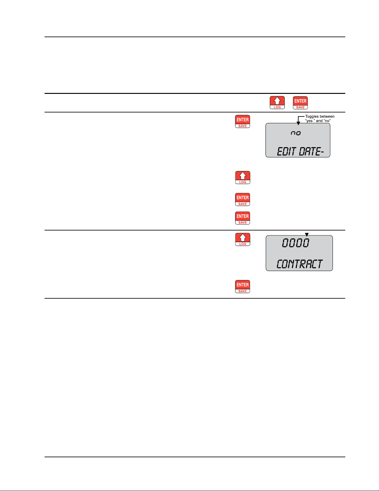
Scanner® 2000 microEFM Section 4
Editing the Contract Hour
A user can set the contract hour from the keypad. The contract hour determines the exact time the daily ow is
logged, and is represented by a four-digit number displayed in military time.
To Edit the Contract Hour:
Enter the Access menu. Press UP ARROW and ENTER
simultaneously.
Locate the Contract Hour setting. Press ENTER four times. The words
“EDIT DATE-TIME” will appear in
the lower display and the word “no”
or “yes” will begin ashing in the top
display (default is “no”).
Press the UP ARROW to change the
setting in the top display to “YES.”
Press ENTER. “DATE MMDDYY” will
appear in the bottom display.
+
Press ENTER a second time.
”CONTRACT HOUR” will appear in
the bottom display.
Enter the contract hour. Press the UP ARROW, repeatedly
if necessary, to change the contract
hour. Each press of the button will
increment the time by 1 hour.
Press ENTER. ”SAVING” will appear
in the bottom display.
75
Page 76
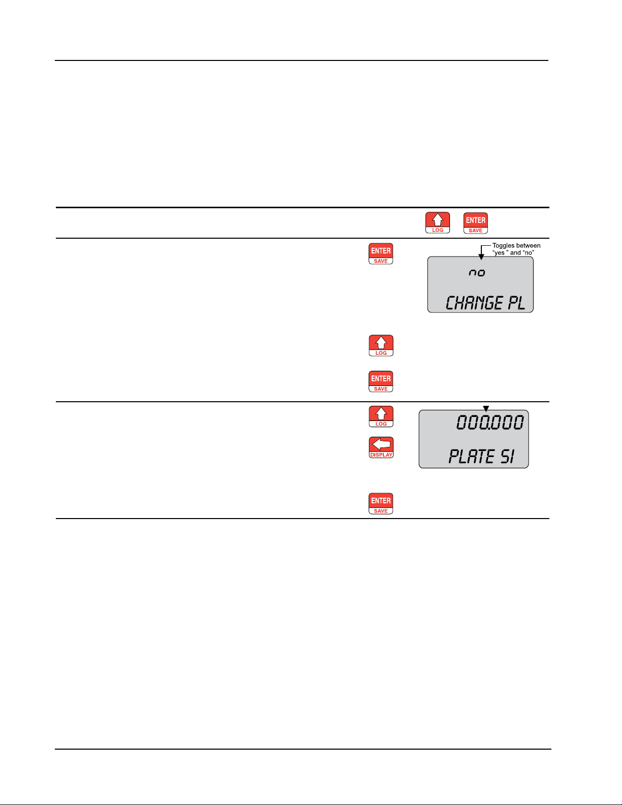
Section 4 Scanner® 2000 microEFM
Editing the Plate Size
When the differential pressure producer in a Scanner 2000 installation is an orice meter and security controls
allow, a user can change the size of the orice plate from the keypad. The plate size is displayed in inches. If
“Strict API compliance” is enabled in the Security menu of the ModWorX™ Pro software, this parameter can
be congured only from the ModWorX™ Pro interface, which allows the operator to put the instrument into
maintenance mode (locked inputs) while the plate change is in process. See Section 3 of the ModWorX™ Pro
Software User Manual, Part No. 9A-30165025, for details.
To Edit the Plate Size:
Enter the Access menu. Press UP ARROW and ENTER
simultaneously.
Locate the Plate Size setting. Press ENTER ve times. The words
“CHANGE PLATE” will appear in the
lower display and the word “no” or
“yes” will begin ashing in the top
display (default is “no”).
Press the UP ARROW to change the
setting in the top display to “YES.”
+
Press ENTER. “PLATE SIZE INCHES” will appear in the bottom
display.
Enter the new plate size. Press UP ARROW until the correct
digit is displayed.
Then press LEFT ARROW to select
the next digit to the left.
Repeat using UP and LEFT arrows to
enter all remaining digits.
Press ENTER.
76
Page 77

Scanner® 2000 microEFM Section 5
Section 5—Scanner 2000 Maintenance
The Scanner 2000 is engineered to provide years of dependable service with minimal maintenance. Batteries
require periodic replacement, and battery life depends on whether battery power is the primary or secondary
power source, the conguration settings of the Scanner 2000, and ambient temperature conditions.
All conguration settings are stored in nonvolatile memory; therefore, conguration settings will not be lost
in the event of battery failure.
The circuit assembly or keypad may also require replacement over the life of the instrument. Replacement
procedures are provided in this section.
WARNING: Before servicing the Scanner 2000, disconnect all power sources/signal sources or
!
verify that the atmosphere is free of hazardous gases.
Lithium Battery Pack Replacement
The Scanner 2000 uses a lithium battery pack with a typical life expectancy of 1 year. Due to the at discharge
characteristics of the lithium battery, it is difcult to determine how much life remains in a battery at any given
time. To preserve conguration and accumulated volume data, replace the battery pack at 1-year intervals.
WARNING: To prevent ignition of hazardous atmospheres, do not remove the cover while cir-
!
cuits are alive. The Scanner 2000 poses no hazard when opened in a safe area.
WARNING: The lithium battery pack that powers the Scanner 2000 is a sealed unit; however,
!
should a lithium battery develop a leak, toxic fumes could escape upon opening the enclosure.
Ensure that the instrument is in a well-ventilated area before opening the enclosure to avoid
breathing fumes trapped inside the enclosure. Exercise caution in handling and disposing of
spent or damaged battery packs. See additional information in Appendix B—Lithium Battery
Information, page B-1.
Important Press the ENTER/SAVE key on the keypad before replacing the lithium battery pack to
save accumulated grand totals and previous day totals for ow run and turbine volume,
energy, and mass to nonvolatile memory. Once the battery pack is replaced and power is
restored to the unit, the last saved accumulated totals will be displayed in the LCD. The
instrument clock will need to be reset following battery replacement. All conguration
and calibration settings are automatically saved to non-volatile memory and are not affected by a temporary loss of battery power.
The lithium battery pack is secured inside the enclosure by a velcro strap and connected to a connector (J1)
near the top of the circuit assembly.
To replace a lithium battery pack in the Scanner 2000, perform the following steps:
1. Unscrew the cover of the enclosure counter-clockwise until it separates from the main body of the enclo-
sure.
2. Using a small standard blade screwdriver, remove the two #4-40 × 7/8” screws located to the right and
left side of the display (Figure 5.1, page 78).
77
Page 78
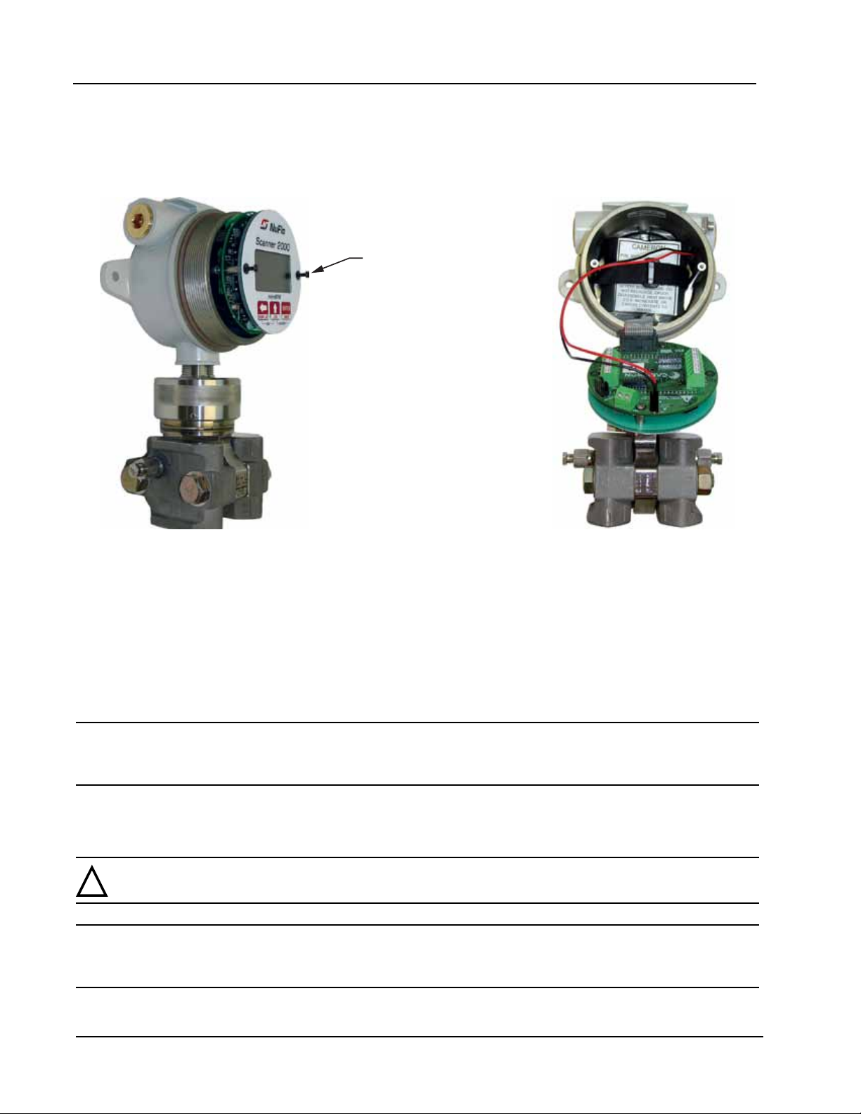
Section 5 Scanner® 2000 microEFM
3. Lift the display/keypad assembly from the enclosure, making sure the circuit assembly does not contact
the enclosure.
4. Loosen the velcro strap, disconnect the battery from the J1 connector on the circuit assembly, and remove
the spent battery pack from the enclosure (Figure 5.1).
Remove screws to
release keypad/circuit board
assembly from enclosure
Figure 5.1—Removal of the battery pack from the enclosure
5. Install the new battery pack in the enclosure in the same position as the original battery pack, and secure
the Velcro tightly around it.
6. Connect the replacement battery pack to the J1 connector.
7. Place the circuit assembly over the standoffs and fasten with the two #4-40 × 7/8” screws, ensuring that
all connector wiring is inside the enclosure.
8. Replace the enclosure cover, threading it onto the enclosure in a clockwise direction.
Important An interruption of power to the Scanner 2000 will cause the internal clock time to be
incorrect. Reset the time using the keypad on the switchplate or the ModWorX™ Pro software. See Editing the Date and Time, page 74, for details.
Circuit Assembly Replacement
WARNING: To prevent ignition of hazardous atmospheres, do not remove the cover while cir-
!
cuits are alive. The Scanner 2000 poses no hazard when opened in a safe area.
Important Static electricity can damage a circuit board. Handle new boards only by their edges,
and use proper anti-static techniques (such as wearing anti-static wrist strap or touching
metal to establish an earth ground) prior to handling a board.
78
Page 79
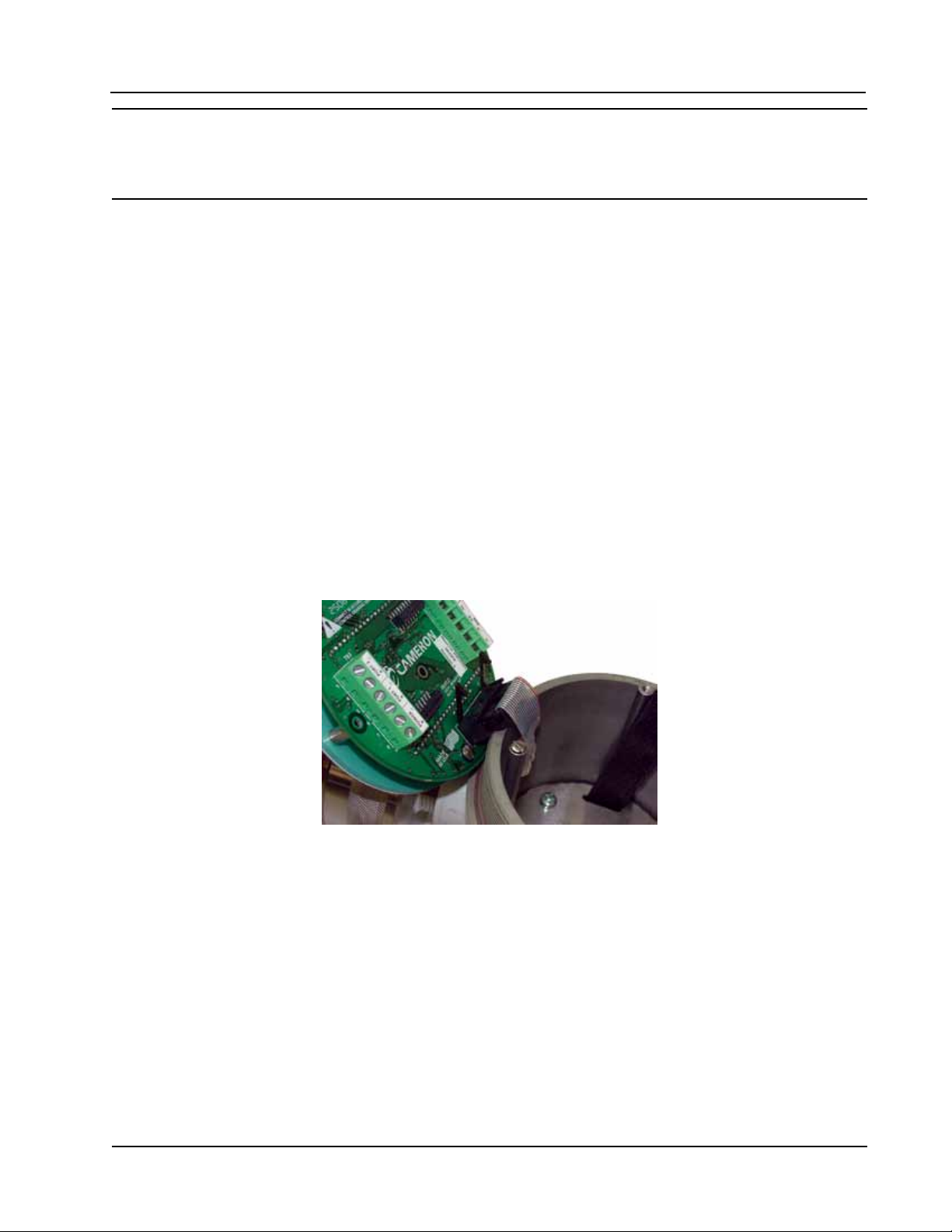
Scanner® 2000 microEFM Section 5
Important If possible, download the conguration settings and all archive logs before replacing the
circuit board. Press the ENTER/SAVE key on the keypad before disconnecting the bat-
tery to save accumulated ow run and turbine volume totals (grand total and current day
total), and energy and mass totals to memory.
To replace the circuit assembly, perform the following steps:
1. Unscrew the cover of the enclosure counter-clockwise until it separates from the main body of the enclo-
sure.
2. Using a small standard blade screwdriver, remove the two #4-40 × 7/8” screws located to the right and
left side of the display (Figure 5.1, page 78).
3. Lift the display/keypad assembly from the enclosure.
4. Record the locations of all cable connections to the circuit board.
5. Using a small standard blade screwdriver, remove all wiring from terminal blocks TB1, TB2, and TB3,
and J2, ensuring that all wiring that is connected to powered circuits is insulated with tape.
6. Unplug the battery cable from connector J1 on the circuit board.
7. Disconnect the sensor ribbon cable from the J5 connector on the circuit board as follows:
a. Lift the latch from the black clip securing the ribbon cable (Figure 5.2).
b. When the latch is fully open, the ribbon cable will release freely.
Figure 5.2—Latch securing the ribbon cable
8. Remove the original circuit board/keypad assembly from the enclosure.
9. Remove the two #4-40 × 5/16” screws fastening the circuit board to the keypad (Figure 5.3, page 80).
10. Remove the keypad ribbon cable from the J7 connector on the LCD side of the circuit board by pressing
in on the sides of the black plastic clip and pulling gently on the clip. Do not pull on the ribbon cable; the
cable will release freely when the clip opens (Figure 5.4, page 80).
11. Remove the circuit board from the enclosure and remove the replacement circuit board from its packag-
ing.
12. Connect the keypad ribbon cable to the J7 connector on the LCD side of the new circuit board by sliding
the end of the ribbon into the black clip as far as it will go and pressing the black plastic clip into the con-
nector until it snaps.
79
Page 80
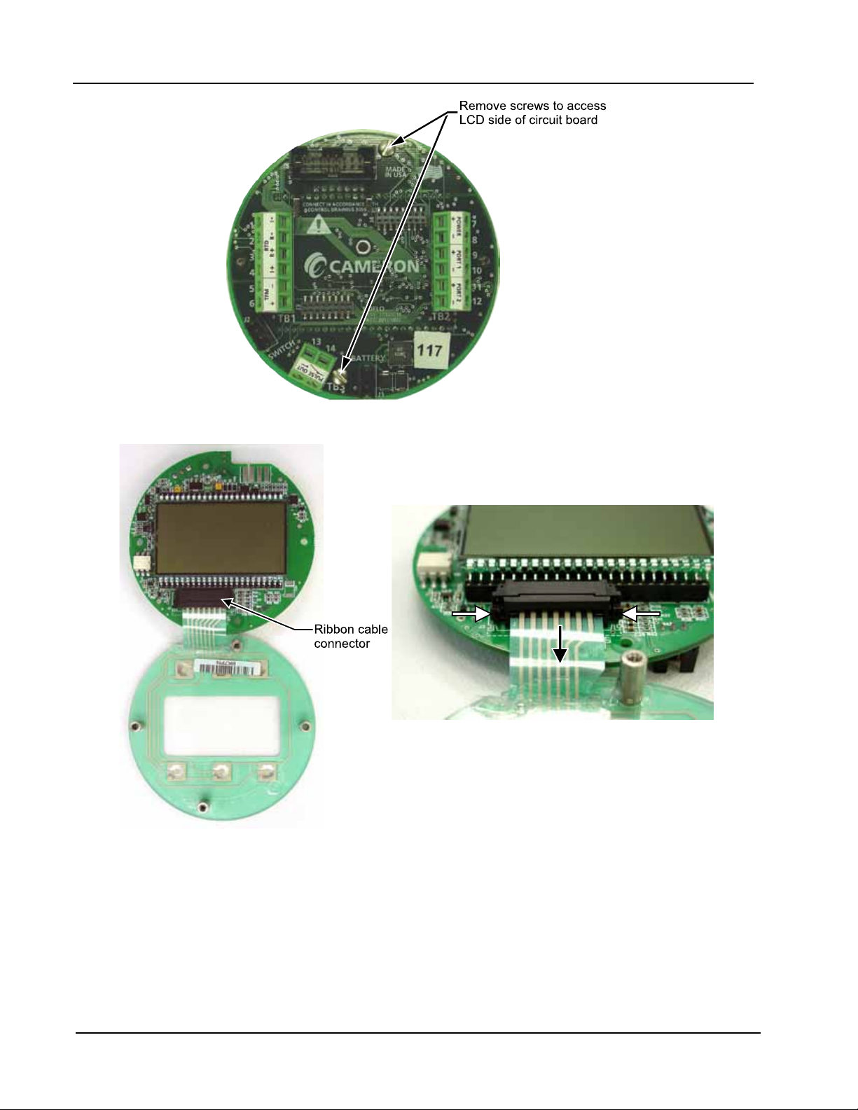
Section 5 Scanner® 2000 microEFM
Figure 5.3—Disassembly of circuit board/keypad assembly
Figure 5.4—To release the ribbon cable from the
connector, press in on the side tabs of the J7 connector
(white arrows) and gently pull forward (black arrow).
13. Connect the circuit board to the keypad with the two #4-40 × 5/16” screws removed in step 9.
14. Reconnect the sensor ribbon cable to the J5 connector at the top of the circuit board, by inserting the ribbon cable into the black clip and securing the latch on the clip to hold it tightly in place.
15. Reconnect the battery cable to connector J1 on the circuit board.
16. Reconnect all wiring to terminal blocks TB1, TB2 and TB3 (and J2, if applicable).
17. Reattach the display/keypad assembly to the standoffs inside the enclosure with the two #4-40 × 7/8”
screws removed in step 2.
80
Page 81

Scanner® 2000 microEFM Section 5
18. Recalibrate the Scanner 2000 and replace the enclosure cover.
Important Do not overlook the need to recalibrate the Scanner 2000. Boards that are shipped inde-
pendently of a Scanner 2000 are not calibrated to compensate for atmospheric pressure;
therefore, a Scanner 2000 will not display accurate pressure readings until it is recalibrated.
19. Re-establish power to the peripheral circuitry.
Keypad Replacement
WARNING: To prevent ignition of hazardous atmospheres, do not remove the cover while cir-
!
cuits are alive. The Scanner 2000 poses no hazard when opened in a safe area.
To replace the keypad of the Scanner 2000, perform the following steps:
1. Unscrew the cover of the enclosure counter-clockwise until it separates from the main body of the enclo-
sure.
2. Using a small standard blade screwdriver, remove the two #4-40 × 7/8” screws located to the right and
left side of the display (Figure 5.1, page 78).
3. Lift the display/keypad assembly from the enclosure.
4. Remove the two #4-40 × 5/16” screws fastening the circuit assembly to the keypad (Figure 5.3, page 80).
5. Disconnect the keypad ribbon cable from the J7 connector on the LCD side of the circuit assembly as fol-
lows:
a. Grasp the black clip between a thumb and forenger (Figure 5.4, page 80).
b. Squeeze both sides of the clip and gently pull to release the clip from the plastic connector that holds
it in place. DO NOT PULL on the ribbon cable. When the black plastic clip is properly disengaged,
the cable will release freely.
6. Remove the old keypad.
7. Connect the ribbon cable of the replacement keypad to the J7 connector on the LCD side of the circuit
assembly as follows:
a. Insert the end of the ribbon cable into the plastic clip.
b. While holding the ribbon cable in place, press the black plastic clip into the connector until it snaps.
8. Mount the circuit assembly to the keypad with the two #4-40 × 5/16” screws removed in step 4.
9. Mount the display/keypad assembly to the enclosure with the two #4-40 × 7/8” screws removed in step 2.
10. Recalibrate the Scanner 2000 if necessary.
11. Replace the enclosure cover and tighten.
81
Page 82

Section 5 Scanner® 2000 microEFM
MVT Replacement
Important Press the ENTER/SAVE key on the keypad before disconnecting the battery to save ac-
cumulated ow run and turbine volume totals (grand total and current day total), and
energy and mass totals to memory.
To replace the MVT of the Scanner 2000, perform the following steps:
1. Unscrew the cover of the enclosure counter-clockwise until it separates from the main body of the enclosure.
2. Using a small standard blade screwdriver, remove the two #4-40 × 7/8” screws located to the right and
leftside of the display (Figure 5.1, page 78).
3. Lift the display/keypad assembly from the enclosure.
4. Unplug the battery cable from connector J1 on the circuit board.
5. Disconnect the sensor ribbon cable from the J5 connector on the circuit board as follows:
a. Lift the latch from the black clip securing the ribbon cable (Figure 5.2, page 79).
b. When the latch is fully open, the ribbon cable will release freely.
6. Loosen the set screw in the side of the MVT adapter.
7. Rotate the adapter counterclockwise to break the connection with the MVT sensor body.
8. Detach the MVT sensor from the adapter, pulling the ribbon cable free.
9. Remove the replacement MVT from its packaging and route the ribbon cable through the adapter and up
into the Scanner 2000 enclosure.
10. Screw the MVT into the adapter until it meets with resistance.
11. Slowly unscrew the MVT sensor until the vents on the sides of the MVT are oriented to the back of the
enclosure.
12. Replace the set screw in the adapter and tighten.
13. Connect the ribbon cable from the sensor to the MVT connector (J5) on the main circuit board.
14. Reconnect the battery cable to connector J1 on the main board.
15. Reinstall the display/keypad assembly in the enclosure, using the screws that were removed in step 2.
16. Recalibrate the Scanner 2000 and replace the cover on the enclosure.
Important Do not overlook the need to recalibrate the Scanner 2000. MVTs that are shipped inde-
pendently of a Scanner 2000 are not calibrated to compensate for atmospheric pressure;
therefore, a Scanner 2000 will not display accurate pressure readings until it is recalibrated.
82
Page 83

Scanner® 2000 microEFM Section 6
Section 6—Spare Parts
WARNING: EXPLOSION HAZARD – Substitution of components may impair suitability for
!
Class I, Division 1 and 2. Use of spare parts other than those identied by Cameron Internation-
al Corporation voids hazardous area certication. Cameron bears no legal responsibility for the
performance of a product that has been serviced or repaired with parts that are not authorized
by Cameron.
Table 6.1—Scanner 2000 microEFM Spare Parts
Qty. Part Number Description
1 9A-30160010 Circuit Assembly, CPU Board
1 9A-30188004 Kit, Scanner 2000 Expansion Board (TFM Input, Pulse
Input, Dual Analog Input, Analog Output, 256 KB Memory)
and Quick Start Guide
1 9A-30166005 Assembly, Switchplate
1 9A-21-XX-YY
(see Table 6.3)
1 9A-1100-1025B-xx
(see Table 6.3)
1 9A-100002605 Desiccant, Humidisorb, Self Regenerate, 2 in. x 2 in. Packet
1 9A-30099004 Battery Pack, 2 “D” Batteries in Series, 7.2V, Lithium, with
1 9A-0112-9015T RS-232 to RS-485 Converter, Serial Port Powered, DB9
1 9A-0027-9030T-XX Cable Assembly, Heavy Duty, Cold Temperature (for use
1 9A-101283116 RS-232 to RS-485 Converter, Serial Port Powered, DB9
1 9A-30054001 Assembly, External Explosion-Proof Switch, with Extension,
1 9A-90017004 Cable Assembly, 3/4 in. NPT Explosion-Proof Union, 2-Pin
1 2295634-01 Kit, NuFlo USB Adapter, Installation CD
1 2295524-01 NuFlo USB Adapter, 3/4 in. NPT, Explosion-proof Union,
Assembly, RTD and Cable, Explosion-Proof (Div. 1), Model
21
(XX=cable length, YY=probe length)
Available cable lengths: 5, 10, 30, or 50 ft
Probe adjustable up to 6 in., 12 in., other (custom)
Assembly, RTD and Cable, Weatherproof (Div. 2)
(XX=cable length)
Available cable lengths: 5, 10, 20, or 30 ft
Probe adjustable up to 6 in.
with Adhesive
Current Limiting Resistor and Diode (CSA)
Connector on Both Ends
with converter 9A-0112-9015T and the optional external
COM port adapter 9A-90017004 (XX=length, 10, 30, 50-ft or
custom)
Connector on PC End, Open Terminals on Instrument End
Fits ¾ in. Female Pipe Thread (CSA)
Connector, 10 in., for External RS-485 Communications
(CSA)
2-Conductor Wire, 12-in.
83
Page 84

Section 6 Scanner® 2000 microEFM
Table 6.1—Scanner 2000 microEFM Spare Parts
1 9A-99177001 Adapter, 1 in. Female Pipe to ¾ in. Male Pipe, Plated Steel
1 9A-99177004 Adapter, 1 in. Female Pipe to ¾ in. Male Pipe, Brass
1 9A-99177005 Adapter, 1 in. Female Pipe to ¾ in. Male Pipe, 316 Stainless
Steel
1 9A-99177006 Adapter, 1 in. Female Pipe to ¾ in. Male Pipe, ATEX
Flameproof, Group IIC, Plated Steel
1 9A-99187001 Union, 1 in. NPT, ATEX Flameproof, Zone 1, Group IIB
1 9A-100017622 Union, 1 in., Explosion-Proof, Plated Steel
1 9A-99187003 Union, 1 in., Explosion-Proof, Brass
1 9A-99187004 Union, 1 in., Explosion-Proof, 316 Stainless Steel
1 9A-90017002 Cable Assembly, 2 Pin Molded Connector, 18 inches long
1 9A-99064006 Pipe Plug, Explosion-Proof, ¾-14 NPT, Hex Socket, Brass
1 9A-99064008 Pipe Plug, Explosion-Proof, ¾-14 NPT, Hex Socket, 316
Stainless Steel
1 9A-99189002 O-Ring, 97mm x 3.5mm, XD-I, for Explosion-Proof
Enclosure
1 9A-99002019 Screw, Set, #8-32 X 3/16, Hex Socket, Stainless
1 9A-100025380 Screw, Pan Head, Slotted, #4-40 X 7/8 Steel Black Oxide
1 9A-100025381 Washer, Flat, #4 Steel Black Oxide
1 9A-30028004 Kit, Pole Mount, Plated Steel
1 9A-30028005 Kit, Pole Mount, Stainless Steel
1 2295583-01 Kit, Sealing, Measurement Canada
1 9A-30165024 Manual, User, Quick Start
1 9A-30165026 Manual, User, Expansion Board Quick Start
1 9A-30074033 Assembly, Installation Software CD and CD Pocket Folder,
ModWorX™ Pro
See Table 6.4 Multi-Variable Transmitter
(selection based on pressure requirements)
84
Table 6.2—Scanner 2000 microEFM Spare Parts (ATEX-Approved)
1 9A-30099006 Battery Pack, 2 “D” Batteries in Series, 7.2V, Lithium, with
Current Limiting Resistor and Diode
1 9A-30188004 Kit, Scanner 2000 Expansion Board (TFM Input, Pulse
Input, Dual Analog Input, Analog Output, 256 KB Memory)
and Quick Start Guide
1 9A-30054002 Assembly, External Explosion-Proof Switch, with Extension,
Fits ¾ in. Female Pipe Thread
1 9A-90017008 Cable Assembly, 3/4 in. NPT Explosion-Proof Brass
Union, 2-Pin Connector, 10 in., for External RS-485
Communications
1 9A-30025002 Tube, Standoff, Stainless Steel, 1.18 in. Hex X 5.98 in. long
with 3/4 in. NPT Male & Female Ends
1 9A-30025003 Tube, Standoff, Stainless Steel, 1.18 in. Hex X 9.00 in. long
with 3/4 in. NPT Male & Female Ends
Page 85

Scanner® 2000 microEFM Section 6
Table 6.2—Scanner 2000 microEFM Spare Parts (ATEX-Approved)
1 9A-30025004 Tube, Standoff, Stainless Steel, 1.18 in. Hex X 12.00 in. long
with 3/4 in. NPT Male & Female Ends
1 9A-30025005 Tube, Standoff, Stainless Steel, 1.18 in. Hex X 18.00 in. long
with 3/4 in. NPT Male & Female Ends
1 9A-X-TTXR-0003 Assembly, RTD and Cable, Flameproof, 3500-mm Cable,
50-mm Probe, for Line Sizes from 2 to 12 inches
Table 6.3—RTD and Cable Assemblies (CSA-Approved)
Select one based on specic application.
Qty. Part No. Description
1 9A-21-05-06 Model 21 RTD, Explosion-proof, 5-ft Cable, 6-in. Probe
1 9A-21-05-12 Model 21 RTD, Explosion-proof 5-ft Cable, 12-in. Probe
1 9A-21-10-06 Model 21 RTD, Explosion-proof 10-ft Cable, 6-in. Probe
1 9A-21-10-12 Model 21 RTD, Explosion-proof 10-ft Cable, 12-in. Probe
1 9A-21-30-06 Model 21 RTD, Explosion-proof 30-ft Cable, 6-in. Probe
1 9A-21-30-12 Model 21 RTD, Explosion-proof 30-ft Cable, 12-in. Probe
1 9A-21-50-06 Model 21 RTD, Explosion-proof 50-ft Cable, 6-in. Probe
1 9A-21-50-12 Model 21 RTD, Explosion-proof 50-ft Cable, 12-in. Probe
1 9A-1100-1025B-05 Assembly, RTD and Cable, Weatherproof (Div. 2), 5-ft
Cable, 6-in. Probe
1 9A-1100-1025B-10 Assembly, RTD and Cable, Weatherproof (Div. 2), 10-ft
Cable, 6-in. Probe
1 9A-1100-1025B-20 Assembly, RTD and Cable, Weatherproof (Div. 2), 20-ft
Cable, 6-in. Probe
1 9A-1100-1025B-30 Assembly, RTD and Cable, Weatherproof (Div. 2), 30-ft
Cable, 6-in. Probe
Table 6.4—Multi-Variable Transmitters
Select one based on specic application. The MVTs listed below have
bottom ports. Side port models are available on request.
Qty. Part No.
(non-NACE)
1 9A-99168041 9A-99168046 9A-99168097 100 PSIA, 30 IN H2O
1 9A-99168042 9A-99168047 9A-99168098 300 PSIA, 200 IN H2O
1 9A-99168075 9A-99168086 9A-99168099 300 PSIA, 840 IN H2O
1 9A-99168076 9A-99168087 9A-99168100 500 PSIA, 200 IN H2O
1 9A-99168043 9A-99168048 9A-99168101 1500 PSIA, 200 IN H2O
1 9A-99168077 9A-99168088 9A-99168102 1500 PSIA, 300 IN H2O
1 9A-99168078 9A-99168089 9A-99168103 1500 PSIA, 400 IN H2O
1 9A-99168079 9A-99168090 9A-99168104 1500 PSIA, 840 IN H2O
1 9A-99168044 9A-99168049 9A-99168105 3000 PSIA, 200 IN H2O
1 9A-99168080 9A-99168091 9A-99168106 3000 PSIA, 300 IN H2O
Part No.
(NACE)
Part No.
(Stainless Bolts)
Description
85
Page 86

Section 6 Scanner® 2000 microEFM
Table 6.4—Multi-Variable Transmitters
Select one based on specic application. The MVTs listed below have
bottom ports. Side port models are available on request.
1 9A-99168081 9A-99168092 9A-99168107 3000 PSIA, 400 IN H2O
1 9A-99168082 9A-99168093 9A-99168108 3000 PSIA, 840 IN H2O
1 9A-99168045 9A-99168050 — 5300 PSIA, 200 IN H2O
1 9A-99168083 9A-99168094 — 5300 PSIA, 300 IN H2O
1 9A-99168084 9A-99168095 — 5300 PSIA, 400 IN H2O
1 9A-99168085 9A-99168096 — 5300 PSIA, 840 IN H2O
86
Page 87
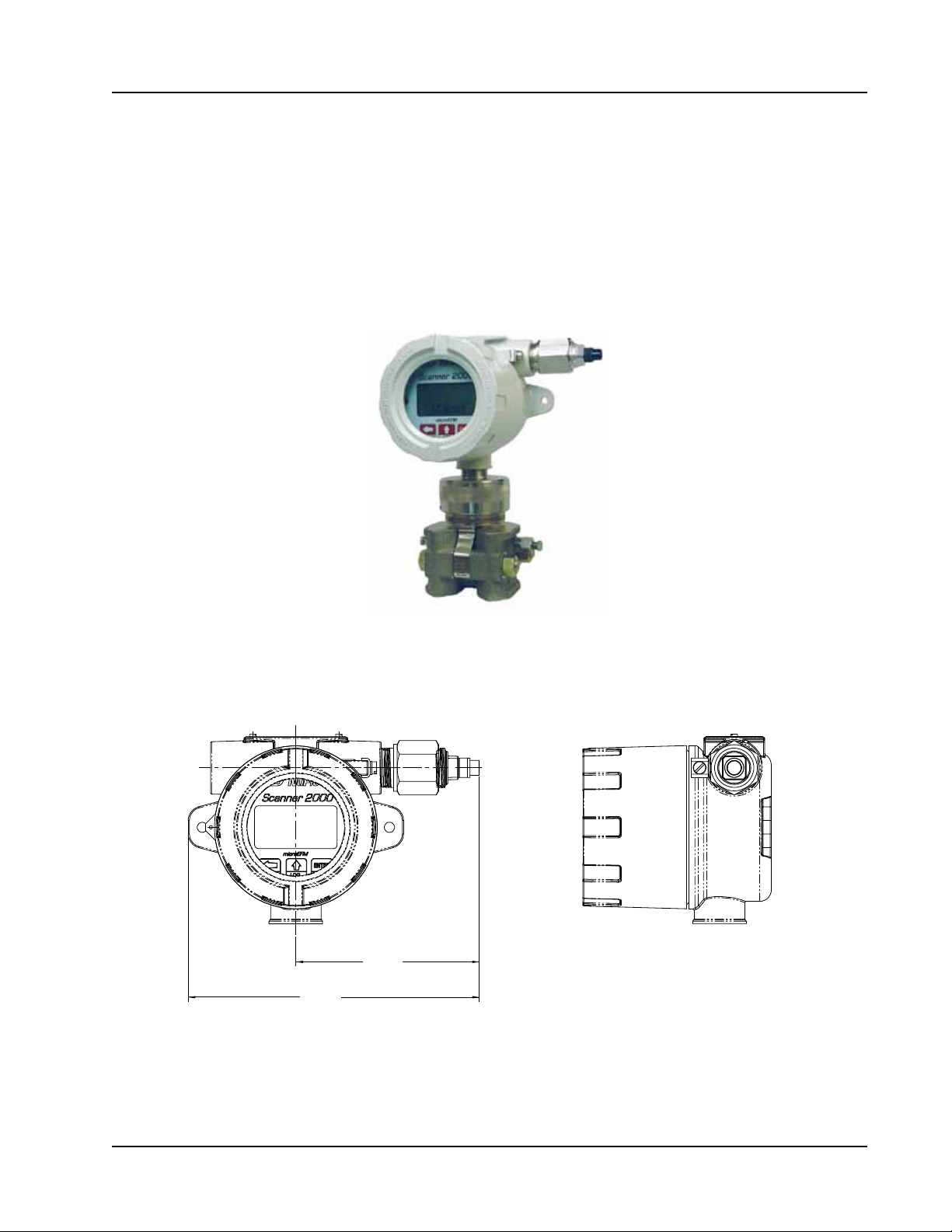
Scanner® 2000 microEFM Appendix A
Appendix A—Scanner 2000 Hardware Options
Explosion-Proof Control Switch
An alternative to the automatic scroll display of parameters on the LCD, an external explosion-proof control
switch (Figure A.1) allows the user to manually select which parameter is displayed on the LCD and view
daily logs instantaneously without removing the instrument cover or connecting the instrument to a laptop
computer. The switch is available in both a CSA-approved model for use in Div. 1 or Div. 2 installations (9A-
30054001), and an ATEX-approved model for Zone 1 installations (9A-30054002).
Figure A.1—Explosion-proof control switch
The switch mounts in either threaded conduit opening in the instrument housing. If both network
communications and an RTD are required, a small junction box must be installed to establish a third conduit
connection location.
4.87
(123.6)
7.72
(196.1)
Figure A.2—Dimensions of explosion-proof control switch; inches (mm)
If the switch is ordered with a Scanner 2000 microEFM, it will be installed prior to shipment. To add a switch
to an existing Scanner 2000, terminate the leads to connector J2 on the main circuit board (Figure A.3).
A-1
Page 88
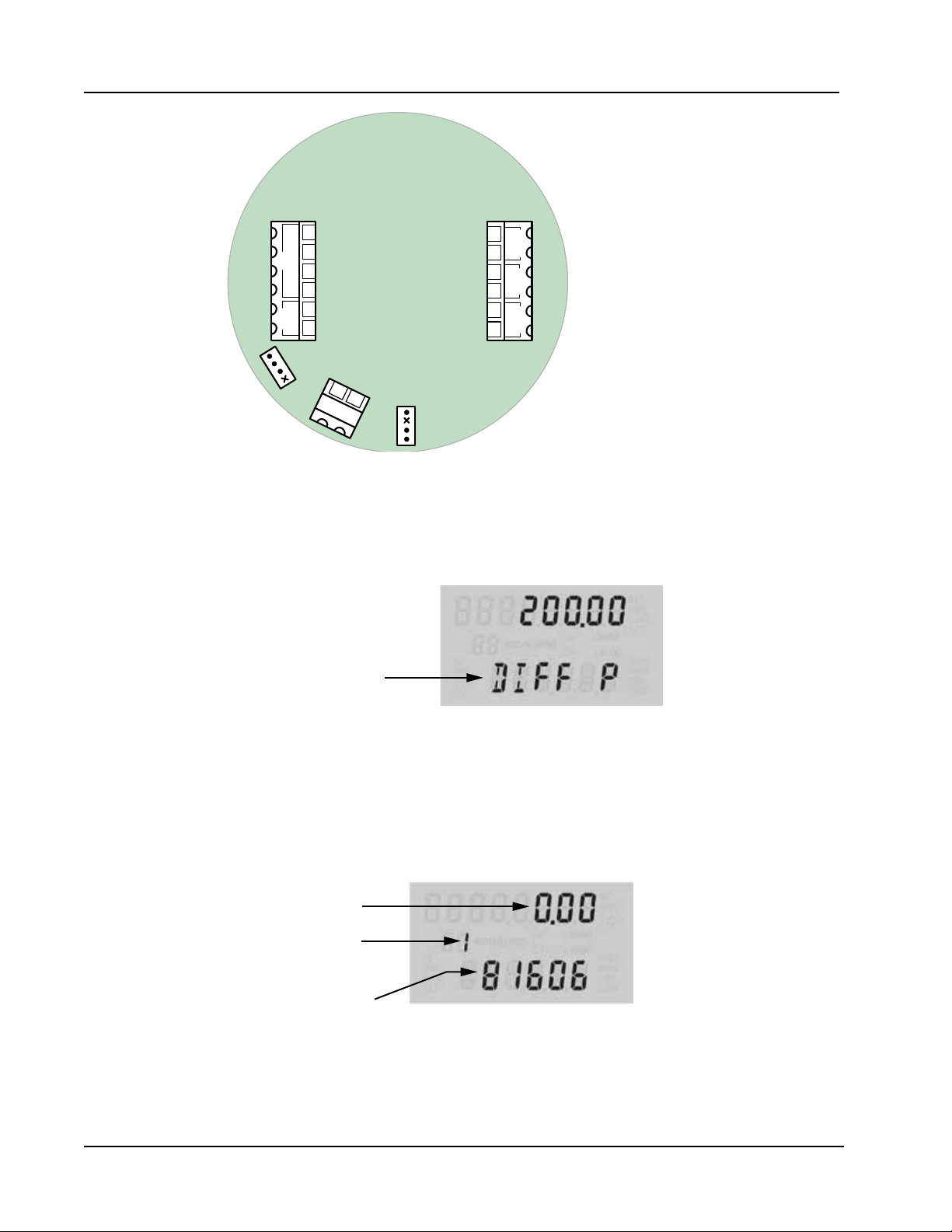
Appendix A Scanner® 2000 microEFM
+
TB2
POWER
7
–
8
+
PORT 2
9
–
10
PORT 1
+
11
–
12
-–
I
1
-
R
2
+
R
3
+
I
4
5
+
TFM 1 RTD
6
J2
TB1
SWITCH
SCANNER 2000
Main Circuit Board
PN: 9A-30160010
13
14
DIG OUT 1
BATTERY
TB3
J1
Figure A.3—Wiring of explosion-proof control switch
To select a display parameter for viewing, press and release the push-button switch. With each subsequent press
of the switch, the LCD will display a new parameter (Figure A.4). Parameters will appear in the order specied
by the user when he congured the display. If the user does not press the button to manually advance to the
next parameter, each parameter will be displayed for 30 seconds before the LCD resumes its automatic scroll.
Parameter changes
when push-button
switch is pressed
Figure A.4—LCD display of real-time measurements
To access daily logs, press and hold the push-button switch for approximately 4 seconds. In the daily log
viewing mode, the LCD will display the daily volume recorded (at the top), the date stamp (bottom), and a
two-digit index that indicates the number of days since the log was created (Figure A.5). When you enter this
mode, the LCD automatically displays the daily log value from the previous day, which is marked by an index
value of “01.”
Volume
Log index
(Days since log
was created)
Date stamp
(MMDDYY)
Figure A.5—LCD display of daily logs
To view logs recorded prior to this date, press the push-button switch repeatedly. The index number will
increase in value (02, 03, etc.) as the logs progress back in time, and the corresponding daily log volumes and
A-2
Page 89
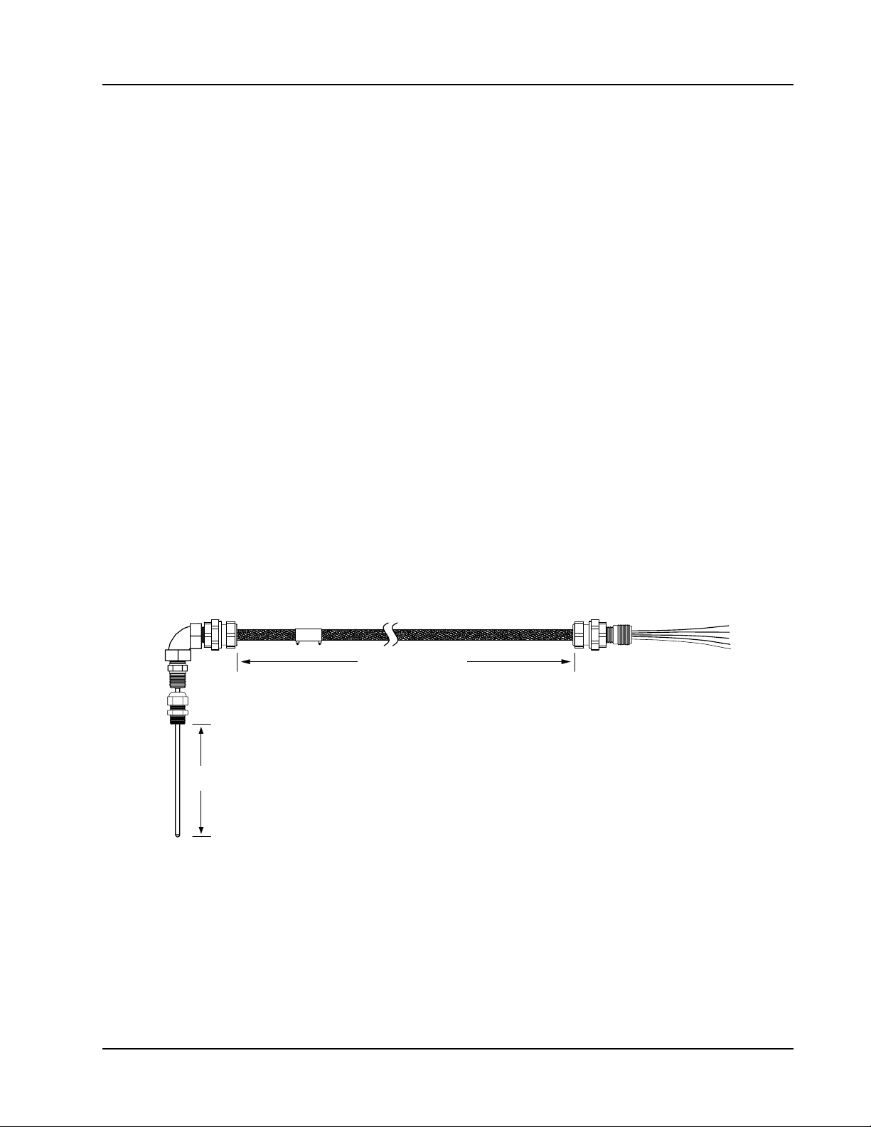
Scanner® 2000 microEFM Appendix A
dates will appear on the LCD. The log display will remain in view for 30 seconds before the LCD resumes its
automatic scroll of display parameters.
RTD Assemblies
Weatherproof RTD Assembly (CSA, Class I, Div. 2)
Cameron’s weatherproof RTD is CSA-certied for use in Class I, Div. 2 hazardous area installations. This
4-wire, 100-ohm RTD assembly has a standard 6-in. adjustable probe and can be ordered with cable lengths of
5, 10, 20, or 30 ft. It is tted with two 1/2-in. MNPT strain reliefs and a 1/2-in. × 3/4-in. reducer for adapting
to various size conduit openings and threadolets. For wiring instructions, see Figure 3.5, page 66. For part
numbers, see Table 6.1—Scanner 2000 microEFM Spare Parts, page 83.
Explosion-Proof RTD Assembly (CSA, Class I, Div. 1)
The Barton Model 21 RTD, shown in Figure A.6 is a 4-wire, 100-ohm weatherproof and explosion-proof RTD
assembly that can be connected to the Scanner 2000 enclosure without conduit in a Class I, Div. 1 installation.
Factory-sealed, armored leads are covered in PVC. The RTD assembly can be ordered with tech cable lengths
of 5, 10, 30, or 50 ft, and is available with a 6-in. or 12-in. RTD probe. Cable length and probe length are
specied in the model part number: 9A-21-XX-YY where XX is the cable length and YY is the probe length.
The Model 21 RTD is CSA-certied for use in Class I, Groups B, C, and D; Class II, Groups E, F and G; and
Class III hazardous area environments.
Each RTD assembly is tted with 1/2-in. and 3/4-in. connectors for adapting to various size conduit openings
and threadolets. The RTD is eld-adjustable for insertion lengths of up to 12 in. For wiring instructions, see
Figure 3.5, page 66. For part numbers, see Table 6.3—RTD and Cable Assemblies (CSA-Approved), page
85.
Cable length
Probe length
Figure A.6—Explosion-proof (Div. 1) RTD assembly
Flameproof RTD Assembly (ATEX, Zone 1)
Cameron offers a ameproof RTD that is ATEX-certied for use in Zone 1 installations. The 4-wire, Class A
sensor is encapsulated in a stainless steel sheath long enough to accommodate line sizes from 2 to 12 inches.
It is attached to a 3500-mm armoured cable. For wiring instructions, see Figure 3.5, page 66. For part numbers,
see Table 6.2—Scanner 2000 microEFM Spare Parts (ATEX-Approved), page 84.
A-3
Page 90
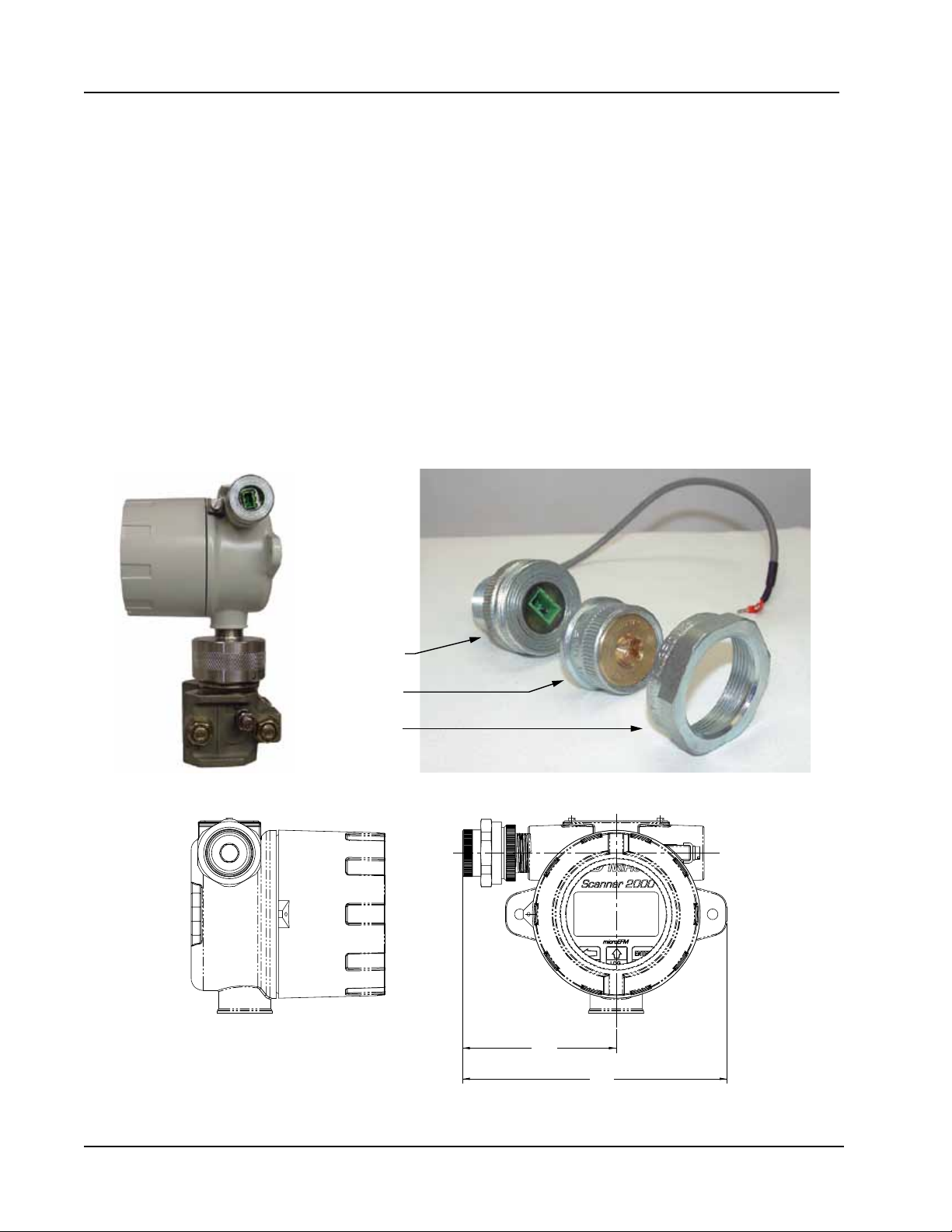
Appendix A Scanner® 2000 microEFM
Communications Adapter (CSA Div. 1 or Div. 2, ATEX Zone 1)
The explosion-proof communications adapter (Figure A.7, page A-4) provides an RS-485 connection for
connecting a laptop or PC to the instrument without removing the instrument cover. When the adapter is
ordered with a Scanner 2000, it is factory installed. It may be relocated to either conduit opening in the
instrument housing. Separate part numbers are provided for CSA and ATEX models, as the ATEX model is
constructed with ATEX-approved materials.
An RS-232 to RS-485 converter cable (available from Cameron’s Measurement Systems Division) is required
for connecting the adapter to a laptop computer. A variety of converter cable options are listed in the Spare
Parts list of this manual (see page 83).
The adapter is shipped pre-assembled in the Scanner 2000 when it is ordered with the unit. The installed
adapter is comprised of an RS-485 adapter socket, a blanking plug, and a union nut. A plug connector that
mates with the RS-485 adapter socket when the adapter is in use is shipped with the device (uninstalled).
This plug connector should be wired to an RS-485 converter cable, and stored with the cable when the COM
adapter is not in use. Wiring instructions for connecting the plug connector to an RS-485 converter cable are
provided in Figure A.9, page A-5.
Adapter socket
Blanking plug
Union nut
Figure A.7—Explosion-proof communications adapter
Figure A.8—Dimensions of explosion-proof communications adapter; inches (mm)
3.95
(100.4)
6.81
(172.9)
A-4
Page 91
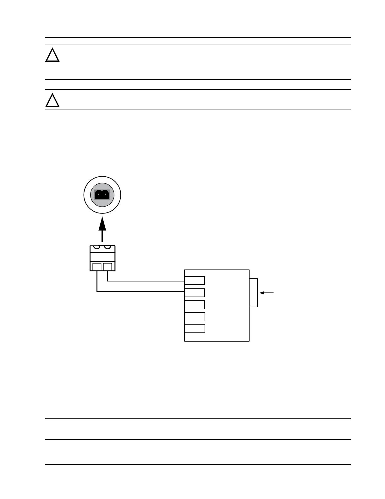
Scanner® 2000 microEFM Appendix A
WARNING: When a hazardous area is present, ensure the union nut and blanking plug a prop-
!
erly tted in the conduit opening. The hazardous location rating applies only when the union
nut and blanking plug are secured in place. When the union is broken, the device is no longer
explosion-proof.
WARNING: Before disassembling the union nut and blanking plug, make sure the area is non-
!
hazardous.
To connect a PC or laptop to the communications adapter, perform the following steps:
1. Unscrew the union nut to expose the connector socket shown in Figure A.7, page A-4. A blanking plug will
be removed with the union nut. Store the union nut and blanking plug in a safe place. (They will need to
be reinstalled when the adapter is not in use.)
2. Connect the plug connector to an RS-485 converter cable, if it is not already attached (Figure A.9).
COM ADAPTER SOCKET
PLUG CONNECTOR
(LEFT AND RIGHT WIRE POSITIONS ARE VALID ONLY
WHEN PLUG IS FACING SOCKET IN POSITION SHOWN)
TD(A)
TD(B)
GND
GND
+12V
Part No. 101283116
RS-485
CONVERTER
RS-232 9-PIN
CONNECTOR
Figure A.9—Wiring of plug connector to Cameron 9-pin RS-232 to RS-485 converter cable
3. Insert the plug connector into the adapter socket.
4. Connect the converter cable to the PC or laptop.
To disconnect the adapter, remove the plug connector (with converter cable attached) from the socket, place
the blanking plug inside the union nut (removed in step 1) and screw the union nut onto the union half to
cover the socket. Hand-tighten to ensure a snug connection.
Note Do not disconnect the plug connector from the RS-232 to RS-485 converter cable when it is not in
use. For best results, store the plug connector with the converter cable.
A-5
Page 92

Appendix A Scanner® 2000 microEFM
Communications Adapter Installation (for adapters purchased separately from a Scanner 2000)
WARNING: If the communications adapter is ordered separately from the Scanner 2000 micro-
!
EFM, the conduit openings in the Scanner 2000 enclosure will be sealed with brass or stainless
steel plugs. Do not remove the plug from the enclosure to install the adapter unless the area is
known to be non-hazardous.
To install a communications adapter purchased separately from a Scanner 2000 microEFM, perform the
following steps:
1. Thread the cable of the adapter through a conduit opening in the instrument housing and screw the adapter
into place.
2. Connect the adapter cable to either communications port on the main circuit board inside the Scanner
2000 housing. See Figure 3.7, page 68, for a wiring diagram.
3. Connect the plug connector to an RS-485 converter cable, if applicable.
USB Communications Adapter (CSA Div. 1 or Div. 2)
The NuFlo™ USB Adapter (Figure A.10) allows a user to connect a computer to the Scanner 2000 using
a standard off-the-shelf USB connector cable for quick and easy downloads without opening the Scanner
enclosure.
The USB adapter is comprised of a USB adapter socket, a blanking plug, and a union nut (Figure A.11). A CD
containing the software for installing the driver is included with the adapter (either (ModWorX Pro or standalone NuFlo USB CD).
When the USB connection is ordered with a Scanner 2000, the USB adapter is pre-installed at the factory.
No eld wiring is required. If the USB adapter is purchased as a kit, see Adapter Kit Installation, page A-8, for
installation instructions.
Important Do not connect the USB adapter to a computer until a USB driver is installed using the
CD provided. ModWorX Pro cannot connect to a Scanner 2000 without these les. See
Using the Adapter, page A-7.
Covering the Adapter
When the USB port is not in use, nest the blanking plug inside the union nut and screw the union nut onto the
adapter to cover the USB socket. Hand-tighten to ensure a snug connection.
A-6
Page 93
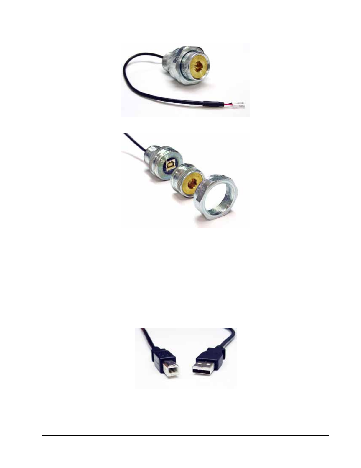
Scanner® 2000 microEFM Appendix A
Figure A.10—NuFlo USB adapter
Figure A.11—NuFlo USB adapter components
Using the Adapter
The CD supplied with the NuFlo USB Adapter contains the drivers required to enable USB communications
for a Scanner 2000 when the NuFLo USB Adapter is installed.
For step-by-step installation instructions, insert the CD in your computer and follow the instructions in the
NuFlo USB Adapter_Readme le. The software will install the appropriate driver that is compatible with your
computer’s operating system.
To complete installation and connect to a Scanner 2000, a user-supplied universal serial bus USB A/B cable is
required (Figure A.12).
Figure A.12—User-supplied USB A/B cable
When the software is fully installed, the adapter can be connected to the computer and used to connect to the
Scanner 2000 via ModWorX Pro (Tools/Select COM Port). For more information on ModWorX Pro, see the
ModWorX Pro User Manual, Part No. 9A-30165025.
A-7
Page 94
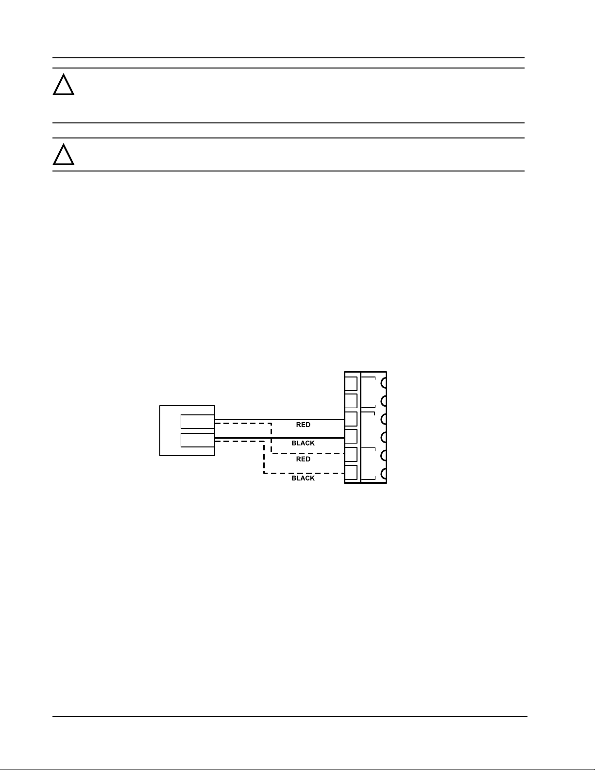
Appendix A Scanner® 2000 microEFM
TB2
WARNING: When a hazardous area is present, ensure the union nut and blanking plug are
!
properly tted in the conduit opening. The explosion-proof rating applies only when the union
nut and blanking plug are secured in place. When the union is broken, the device is no longer
explosion-proof.
WARNING: Before disassembling the union nut and blanking plug, make sure the area is non-
!
hazardous.
Adapter Kit Installation
If the NuFlo USB adapter is purchased as a kit, install it in the Scanner 2000 according to the steps below.
The USB adapter is comprised of a USB adapter socket, a blanking plug, and a union nut. The blanking plug
and union nut are connected to the adapter only when the USB port is not in use.
1. Remove the plug from a conduit opening in the Scanner 2000 enclosure.
2. Thread the cable of the adapter through the conduit opening and screw the adapter into place.
3. Wire the adapter cable to either communications port on the Scanner 2000 main circuit board as shown in
the wiring diagram (black wire to negative terminal).
4. If the USB port will not be used immediately, nest the blanking plug inside the union nut and screw the
union nut onto the adapter to cover the USB socket. Hand-tighten to ensure a snug connection.
+
POWER PORT 2 PORT 1
PORT 1 OR PORT 2 CAN BE
CONNECTED TO THE USB ADAPTER
+
USB
CONNECTOR
Figure A.13—Wiring of NuFlo USB adapter (required only when purchased as a kit)
+
7
–
8
9
–
10
11
–
12
Input/Output Expansion Board (Not Available with Fieldbus)
With the installation of the Scanner 2000 input/output expansion board, the instrument can support up to three
ow runs simultaneously—a ow run and two turbine meter runs. All inputs and outputs are congured with
ModWorX™ Pro software provided with each Scanner 2000 microEFM. See the ModWorX™ Pro Software
User Manual, Part No. 9A-30165025, for details.
The expansion board shown in Figure A.14, page A-9, includes the following inputs and outputs:
• 2 analog inputs (can be congured for 0-5 V, 1-5 V or 4-20 mA)
• 1 turbine meter input
• 1 pulse input
• 1 analog output (4-20 mA)
A-8
Page 95
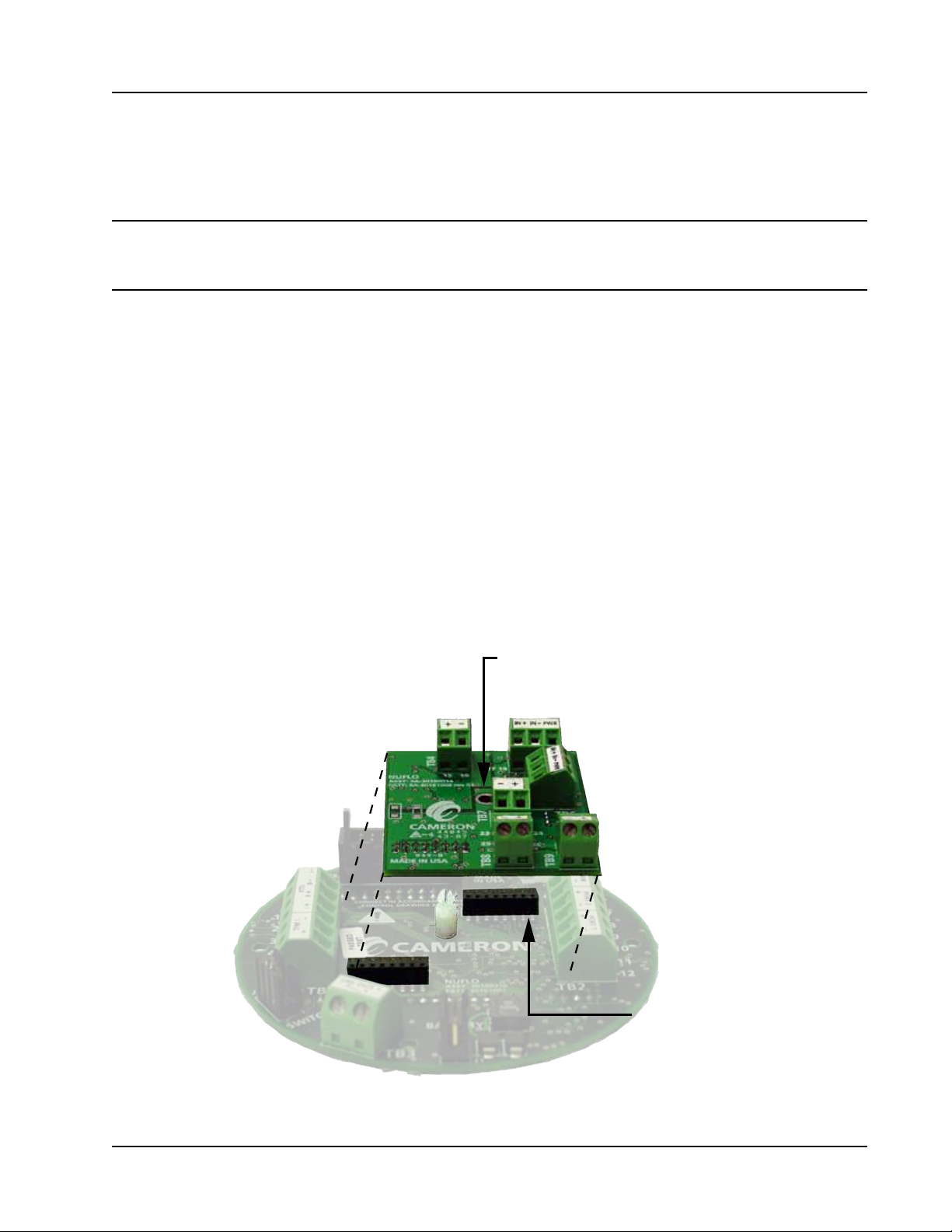
Scanner® 2000 microEFM Appendix A
If the expansion board is ordered with a Scanner 2000, it is installed at the factory. If the board is purchased
separately, the user will need to install it on the Scanner 2000 main board using the following instructions.
Installation (for boards purchased separately from a Scanner 2000)
Important Before installing the expansion board, remove all power from the Scanner 2000
(battery and external power). Remove wiring from the main board if necessary to guide
the expansion board into position.
The expansion board attaches to two headers positioned between the two large green terminal blocks on the
main board. To install, perform the following steps:
1. Remove the standoff from packaging and push it into the hole near the middle of the main board until it
snaps into place.
2. Guide the expansion board over the standoff and align the pins on the under side of the expansion board
with the headers on the main board. FAILURE TO ALIGN PINS AND HEADERS CAN RESULT IN
DAMAGE TO THE BOARD. When the board is positioned correctly, the text on both boards should face
the same direction.
3. Gently press the expansion board and the main board together until the expansion board snaps into place
over the standoff.
4. Restore eld wiring connections to the main board, if applicable, and install eld wiring on the expansion
board.
5. Restore power to the Scanner 2000 and reboot the Scanner to allow it to detect the expansion board.
Align hole in
expansion board
with stando.
Align pins on back
of expansion board
with black headers.
Figure A.14—Scanner 2000 input/output expansion board
A-9
Page 96
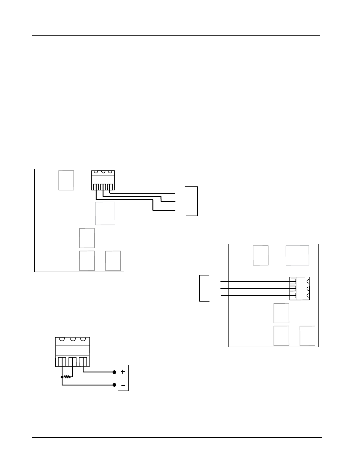
Appendix A Scanner® 2000 microEFM
ANALOG INPUT 1 (TB5)
17 18 19
TB9
TB8 TB7
TB6
TB5
1-5 VDC
TRANSMITTER
POWER
RETURN
SIGNAL
PWRIN+ IN-
TB4
Expansion
Board PN:
9A-30160014
ANALOG INPUT 2 (TB6)
20
21
TB9
TB8 TB7
TB6
TB5
PWRIN+ IN-
22
1-5 VDC
TRANSMITTER
POWER
RETURN
SIGNAL
TB4
Expansion
Board PN:
9A-30160014
4-20 mA
TRANSMITTER
Resistor Required
(250-ohm recommended)
17 18 19
PWRIN+ IN-
TB5
4-20 mA TRANSMITTER WIRING
(CAN BE USED WITH ANALOG INPUT 1 OR 2)
Wiring Diagrams
Analog Inputs 1 and 2
The analog inputs, which can be congured for a 0-5 V, 1-5 V or 4-20 mA signal, can be used to receive
readings from a pressure or temperature transmitter for use in AGA-7 gas calculations. Alternatively, they can
be used to log measurements from any device with a 0-5 V, 1-5 V or 4-20 mA output.
Transmitter power is provided by the Scanner 2000 only when the Scanner is externally powered. The output
voltage equals the input voltage less 0.25 VDC, and is limited to 20 mA.
If a 4-20 mA transmitter is used, a resistor must be added to the circuit, as shown in Figure A.15. The
expansion board circuit will support a resistor range of 200 to 300 ohms; 250 ohms is recommended.
Figure A.15—0-5 V, 1-5 V and 4-20 mA analog input wiring
A-10
Page 97
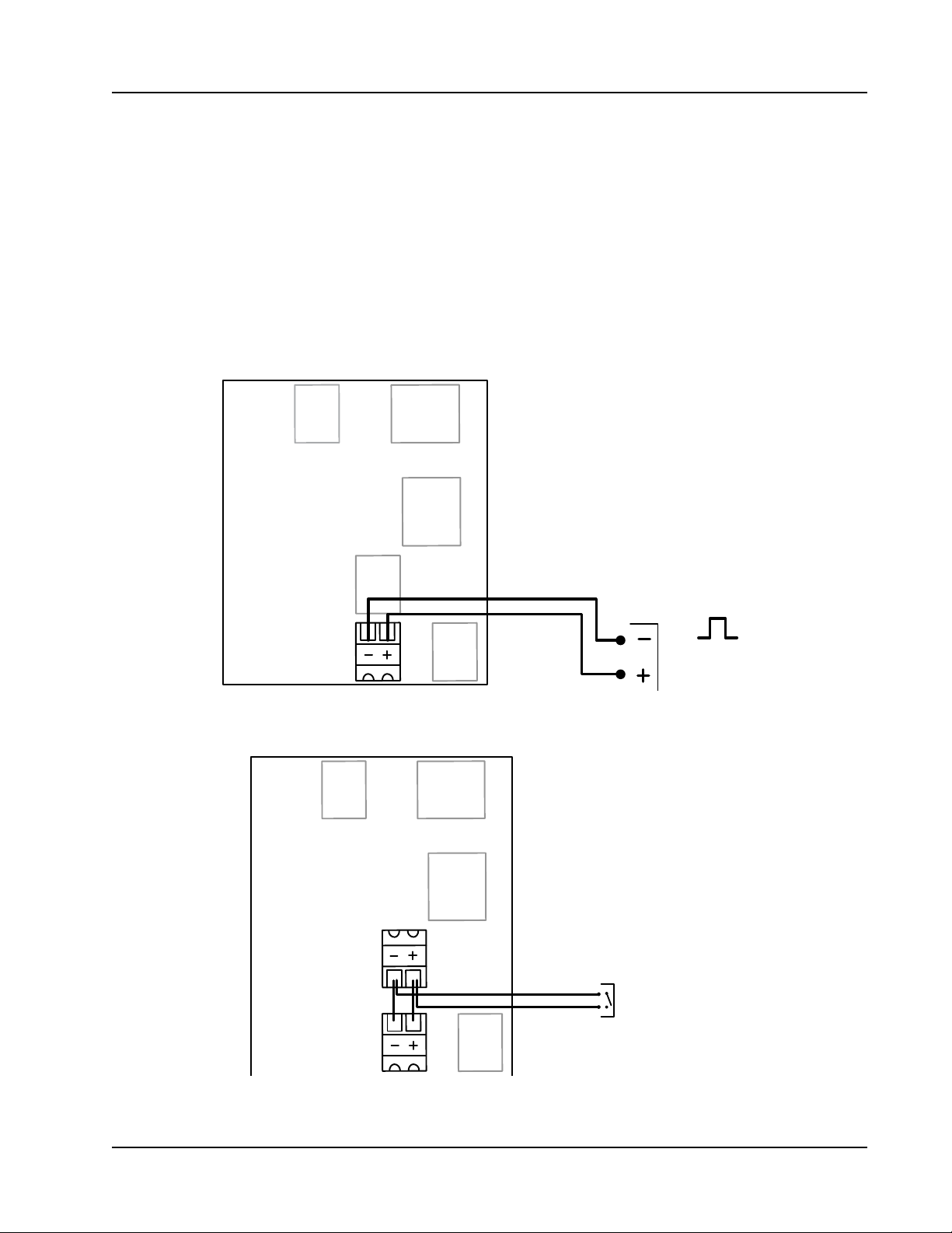
Scanner® 2000 microEFM Appendix A
Pulse Input
The pulse input provides an optically isolated input for high-amplitude pulse (frequency) signals, which
includes signals from a turbine meter equipped with a preamplier (Figure A.16, top diagram) or signals from
a positive displacement meter (Figure A.16, bottom diagram).
The Scanner 2000 can calculate ow from no more than two pulse (frequency) inputs at a time. Therefore, a
pulse input can be used simultaneously with only one turbine input (main board or expansion board).
The pulse input can also be used as a status input for monitoring a parameter via Modbus
®
registers. See Pulse
Input for Status Indication, page D-25, for details.
PULSE INPUT (TB8)
TB4
Expansion
Board PN:
9A-30160014
25 26
TB8 TB7
TB5
TB6
TB9
PULSE INPUT/SWITCH (TB7 &TB8)
TB4
TB5
PULSE INPUT
3 TO 30 VDC
Expansion
Board PN:
9A-30160014
Figure A.16—Pulse input wiring
TB6
23
25
TB8 TB7
24
SWITCH CLOSURE
26
TB7 AND TB8 ARE CONNECTED BY JUMPER;
TB9
TB7 IS THEN WIRED TO THE SWITCH.
A-11
Page 98
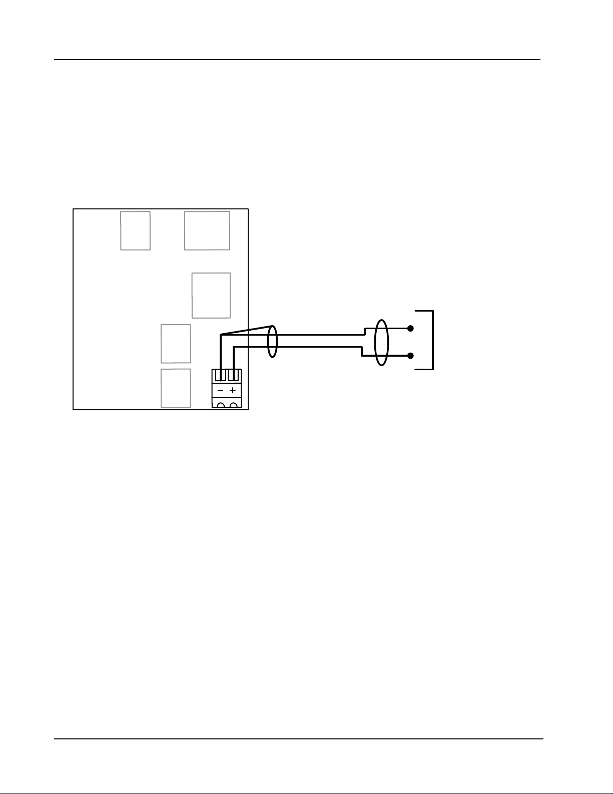
Appendix A Scanner® 2000 microEFM
Turbine Flowmeter Input 2
Turbine Input 2 (Figure A.17) accepts a turbine owmeter input signal generated by a magnetic pickup.
The Scanner 2000 can be congured to use this signal to calculate and display instantaneous ow rates and
accumulated totals. Turbine Input 2 is in addition to the turbine input on the main circuit board. When the
expansion board is installed, a differential pressure ow run and two turbine runs can be monitored and
logged simultaneously.
TURBINE INPUT (TB9)
TB9
TB6
2827
TB5
BLACK
RED
B
TURBINE
MAGNETIC PICKUP
A
TB4
Expansion
Board PN:
9A-30160014
Figure A.17—Turbine Input 2 wiring
TB8 TB7
Analog (4-20 mA) Output
The 4-20 mA output provides a linear current output that can be congured using ModWorX Pro software to
represent any parameter in the holding registers. This output requires a two-conductor cable to be connected
to an 8 to 30 VDC power supply (voltage required is dependent on loop resistance) and a current readout
device to be located in the remote location. See the ModWorX Pro Software User Manual for information on
conguring zero and full-scale values using ModWorX Pro software.
The graph below the wiring diagram in Figure A.18, page A-13 shows the minimum voltage required to power the
instrument for a given loop resistance. In addition, the mathematical relationship between loop voltage and
load resistance is given. For example, if a power supply voltage of 24 volts is available to power the current
loop, the maximum load resistance would be 800 ohms.
A-12
Page 99
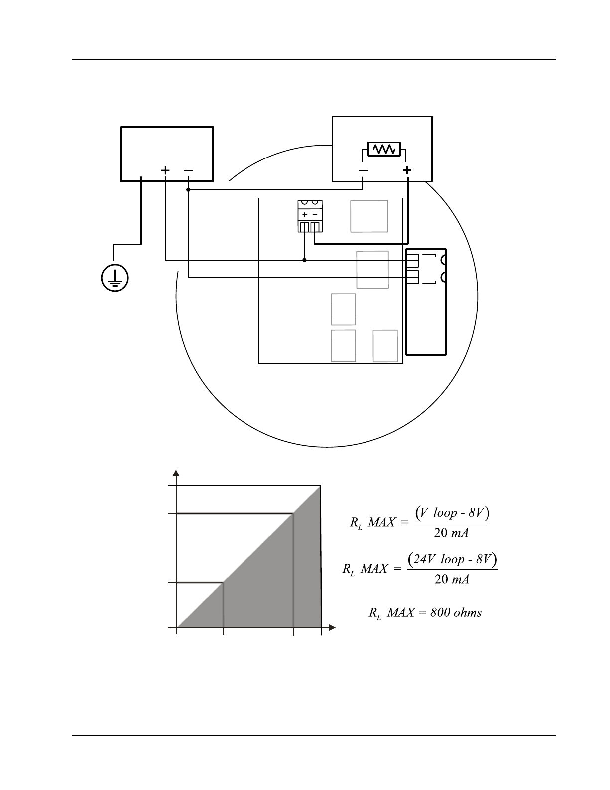
Scanner® 2000 microEFM Appendix A
ANALOG OUTPUT (TB4)
(WITH POWER SUPPLIED VIA MAIN BOARD (TB2)
POWER SUPPLY
8-30 VDC
GND
GROUND
SCREW INSIDE
ENCLOSURE
TB4
15 16
Expansion
Board PN:
9A-30160014
SCANNER 2000
Main Circuit Board
PN: 9A-30160010
ANALOG DEVICE
TB5
TB6
TB8 TB7
TB9
TB2
Resistor may be
*
included in readout
device.
+
POWER
7
–
8
9
10
11
12
1100
800
200
LOAD RESISTANCE (OHMS)
0
8 12 24 30
LOOP SUPPLY VOLTAGE ( VDC)
Figure A.18—Analog (4-20 mA) output wiring
OPERATING
REGION
A-13
Page 100

Appendix A Scanner® 2000 microEFM
Measurement Canada Seal Kit
Measurement Canada has approved the use of the Scanner 2000 for custody transfer applications when it is
installed in accordance with the conguration and sealing provisions cited in Measurement Canada Approval
No. AG-0557C.
Measurement Canada compliance requires both the installation of a lead seal on the device and the enabling
of a custody transfer device seal in software that effectively prevents the user from changing the device
conguration without breaking the seal. For best results, congure the Scanner 2000 using ModWorX Pro
software prior to installing the seal kit. See the ModWorX Pro User Manual, Part No. 9A-30165025, for
information on conguring the device.
Seal kit components are packaged in a small plastic bag for shipment with Measurement Canada approved
devices. The seal kit includes the following components:
• a double-strand seal wire with a lead seal attached to one end
• an Allen head screw drilled to accept a seal wire
• a small Allen wrench
• an S-shape metal bracket drilled to accept a seal wire
• a circuit board jumper (for activating the device conguration lock)
Measurement Canada approved units can be identied by a secondary tag containing unit specications and
the Measurement Canada approval number. The tag is afxed to the outside of the Scanner 2000 enclosure
prior to shipment.
Seal Kit Installation
To install the Measurement Canada seal kit, perform the following steps.
1. Remove the cover from the Scanner 2000.
2. Remove the seal kit components from the plastic bag.
3. Remove the two screws from the Scanner 2000 switchplate and set aside.
4. Install the seal kit jumper as follows.
a. Pull the switchplate and circuit board assembly forward to access the back side of the circuit board.
b. Locate the J2 receptacle labeled “SWITCH” and insert the jumper into the header. (See Figure A.19,
page A-15)
A-14
 Loading...