

Page 1

BARTON® MODEL 752 & 752A
DIFFERENTIAL PRESSURE
TRANSMITTERS
For Nuclear Service
Part No. 9A-C10820, Rev. 02
Contents
Safety ............................................................................................................ 2
Section 1—Introduction ................................................................................. 3
General ......................................................................................................... 3
Product Description....................................................................................... 3
Differential Pressure Unit ......................................................................... 3
Electronic Transmitter................................................................................ 4
Power Supply ............................................................................................ 4
Zero and Span Control.................................................................................. 4
Zero Control .............................................................................................. 4
Span Control ............................................................................................. 5
Specications ............................................................................................... 5
Qualication............................................................................................... 7
Section 2—Theory of Operation .................................................................... 9
Basic Components ........................................................................................ 9
Differential Pressure Unit (DPU) ............................................................... 9
Electronic Transmitter...............................................................................11
Basic Operation ...........................................................................................11
Surge Voltage Protection Circuit .............................................................11
Reverse Polarity Protection ......................................................................11
Regulator ..................................................................................................11
Strain Gage Bridge Network ................................................................... 12
Signal Amplier........................................................................................ 12
Current Amplier...................................................................................... 12
Temperature Compensation........................................................................ 12
Section 3—Installation, Startup, and Shutdown ........................................ 13
Overview ..................................................................................................... 13
Unpacking/Inspection.................................................................................. 13
Initial Calibration Check .............................................................................. 13
Mounting ..................................................................................................... 13
Wall or Rack Mounting ............................................................................ 13
Piping Guidelines ........................................................................................ 14
Electrical Connections ............................................................................... 14
Loop Resistance Calculations ................................................................. 16
Maximum Loop Resistance ..................................................................... 17
EMI/RFI Shielding ....................................................................................... 17
November 2015
User Manual
Page 2

Startup Procedure ....................................................................................... 17
Shutdown Procedure .................................................................................. 18
Section 4—Calibration and Maintenance ................................................... 19
General Field and Periodic Maintenance .................................................... 19
Electronic Transmitter.............................................................................. 19
Differential Pressure Unit (DPU) ............................................................. 19
Calibration .................................................................................................. 19
Electrical Connections for Calibration ..................................................... 20
Calibration Checkpoints .......................................................................... 21
Calibration Procedure ............................................................................ 21
DPU Inspection and Cleaning ..................................................................... 22
Troubleshooting .......................................................................................... 23
Section 5—Assembly Drawing and Parts List ........................................... 27
Section 6—Dimensional Drawings ............................................................. 31
Appendix A ...................................................................................................A-1
Safety Precautions .....................................................................................A-1
Flow Application .....................................................................................A-1
Liquid Level Applications ........................................................................ A-1
Typical Piping/Startup Examples ...............................................................A-2
Gas Flow, DPU Above Run ....................................................................A-2
Gas Flow, DPU Below Run ....................................................................A-3
Gas Flow, Hydrates Present...................................................................A-4
Steam Flow, DPU Below Run.................................................................A-5
Liquid Flow, DPU Above Run .................................................................A-6
Liquid Flow, DPU Below Run .................................................................A-7
DPU Below Tank with Reference Leg: Hot or Cool Liquids ....................A-8
DPU Level with Tank Bottom: Cool Liquids with Pressurized Tank ........A-9
DPU Below Tank Bottom: Cool Liquids with Pressurized Tank ............A-10
Product Warranty .....................................................................................A-11
Product Brand ............................................................................................................
Safety
A-11
Before installing this product, become familiar with the installation instructions presented in Section 3 and all safety notes throughout.
WARNING:Thissymbolidentiesinformationaboutpracticesorcircum-
!
stances that can lead to personal injury or death, property damage, or
economic loss.
CAUTION: Indicates actions or procedures which if not performed correctly
IMPORTANT: Indicates actions or procedures which may affect instrument operation or
2
may lead to personal injury or incorrect function of the instrument
or connected equipment.
may lead to an instrument response that is not planned.
Page 3
Model 752 and 752A Differential Pressure Transmitters Section 1
Section 1—Introduction
General
The Model 752 and 752A Differential Pressure Transmitters provide a 4-20
mA or 10-50 mA signal that is proportional to differential pressure and transmits it to remote receiving, control, or readout devices. Sources of differential
pressure include liquid level and specic gravity changes in vessels; ow of
liquids and gases through orice plates, nozzles or venturis; pressure drop
across lters and static line pressures, etc.
Product Description
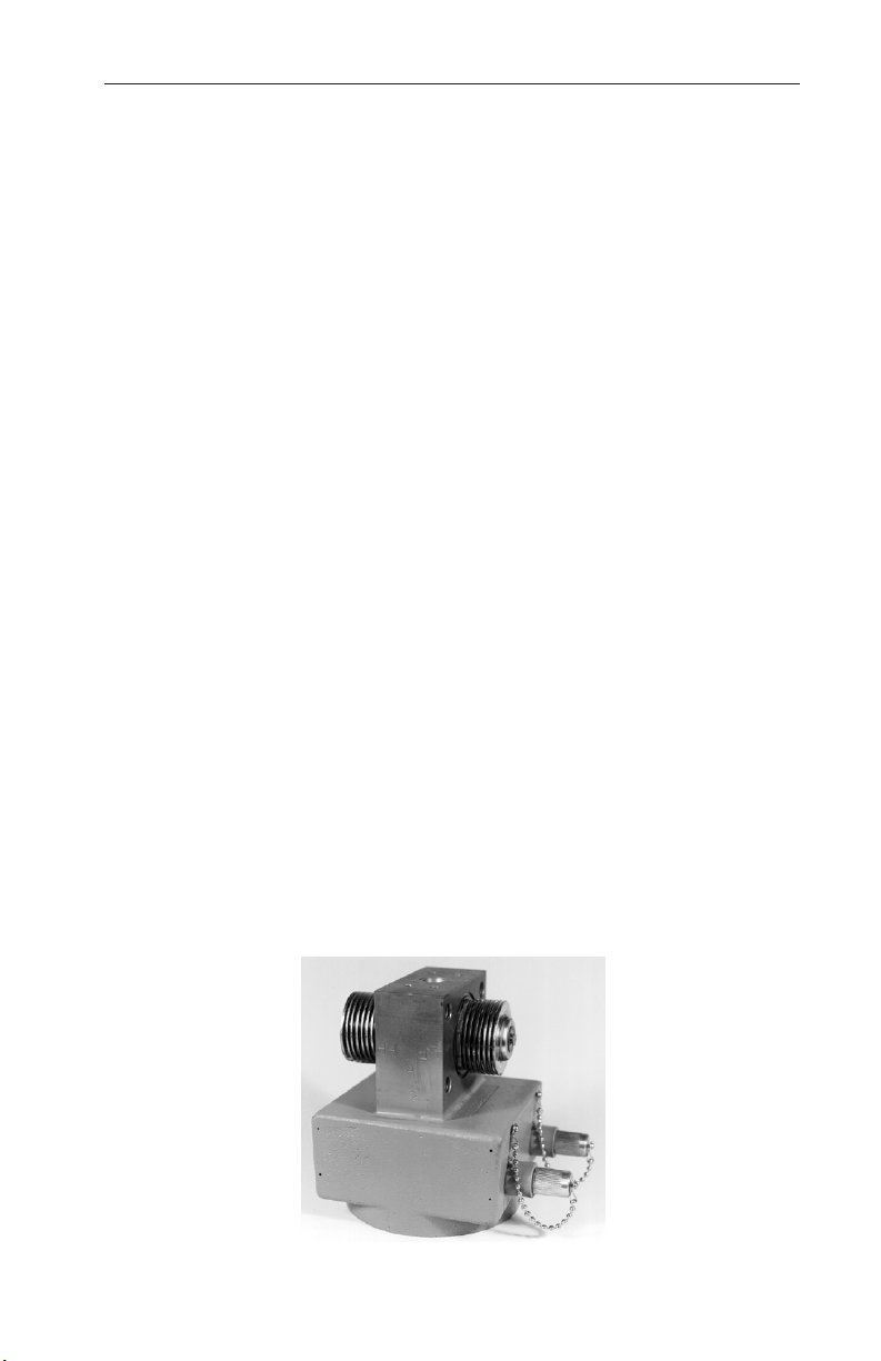
The Model 752 and 752A transmitters combine a differential pressure unit
(DPU) with an electronic circuit. The 4-20 mA or 10-50 mA output is compatible with a wide range of electronic receiving, control, and readout equip-
ment. The instrument utilizes miniaturized hybrid electronic circuits and a
molecular-bonded strain gage sensing cantilever beam, actuated directly by
the bellows' travel within the DPU. In many applications, the electrical connections are contained within a junction box, as shown in Figure 3.1, page 15.
However, the junction box is optional.
Differential Pressure Unit
The mechanical actuating device for the Model 752 and 752A transmitters
is a dual bellows assembly enclosed by a set of two pressure housings. The
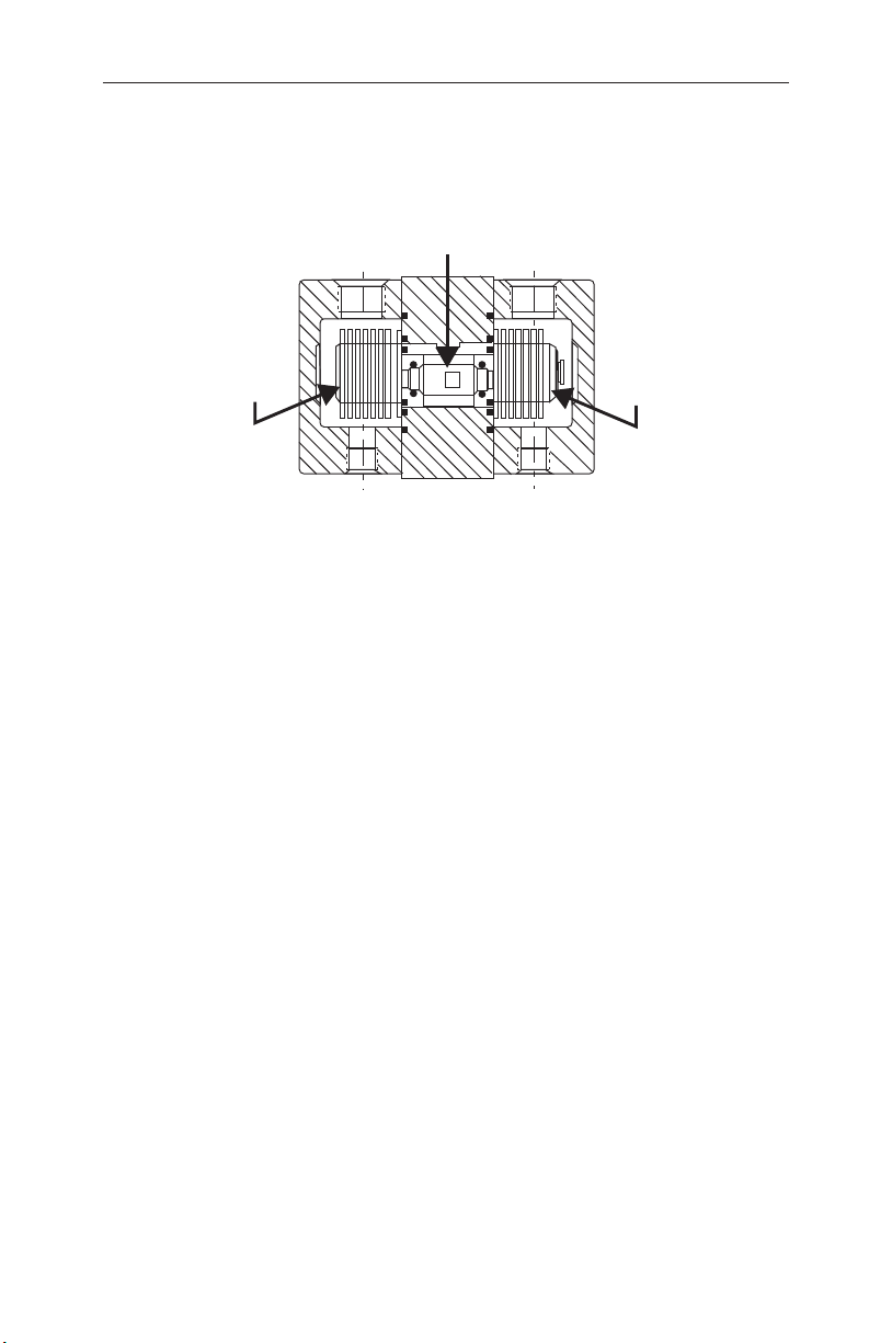
assembly (Figure 1.1 below and Figure 2.1, page 9) consists of two internallyconnected bellows, a center block, overrange valves, a temperature compensator, a strain gage assembly, and range springs. The internal volume of the
bellows and center block is lled with a clean, non-corrosive, non-conductive
liquid with a low freezing point, and sealed. The motion-sensing cantilever
beam is also sealed within this environment.
Figure 1.1—Bellows unit assembly (BUA)
3
Page 4

Section 1 Model 752 and 752A Differential Pressure Transmitters
Electronic Transmitter
The electronic transmitter supplies a 4-20 mA or 10-50 mA direct current output signal that is proportional to the differential pressure sensed by the DPU.
The output signal is transmitted over a two-wire transmission line to remote
receiving devices.
Power Supply
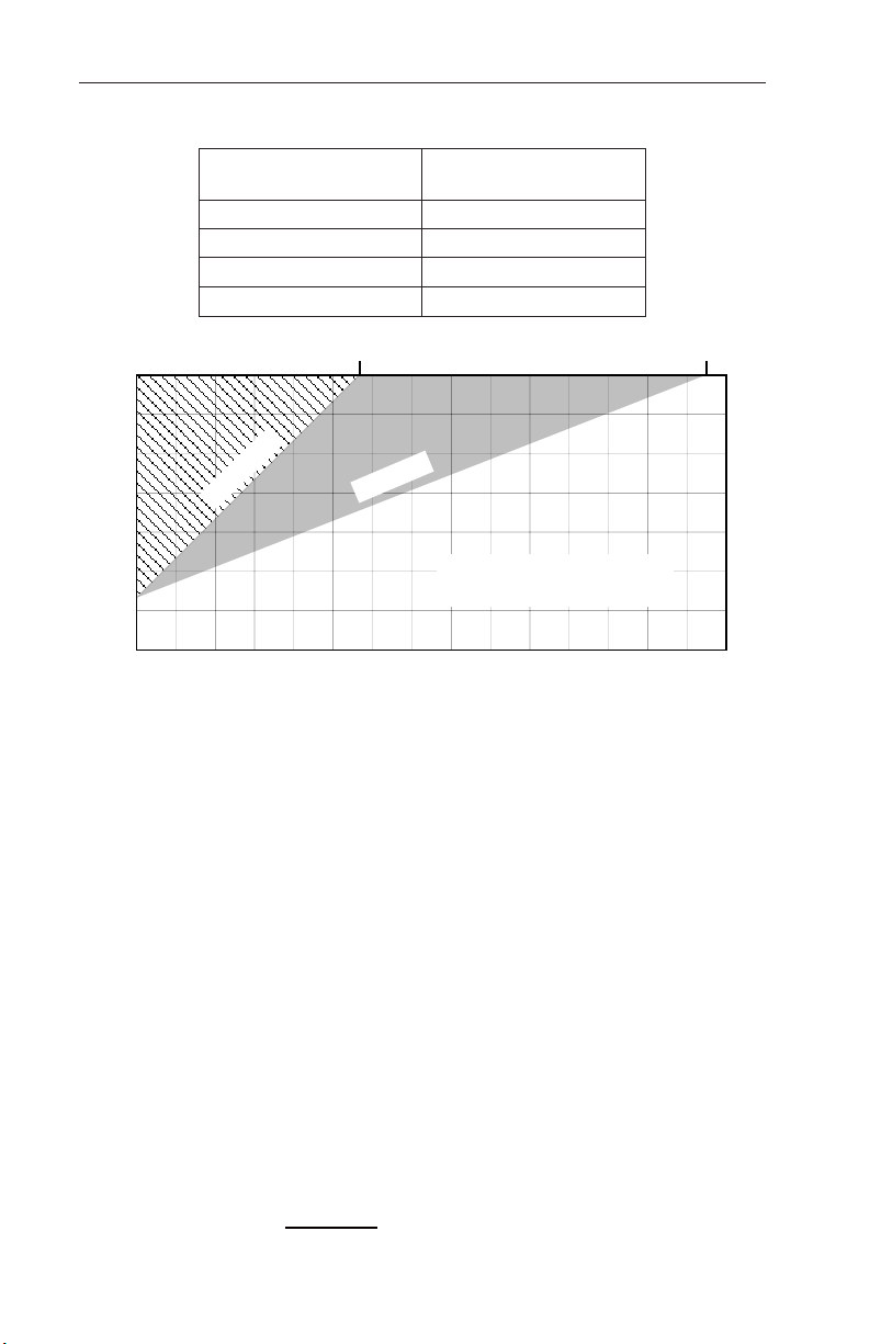
A regulated direct current (DC) power supply is required to operate the transmitting loop. The voltage required will depend on the total loop resistance
(load resistor, cable wiring, and any other resistance in the loop) as shown in
Figure 3.3, page 16. Table 3.1, page 16 shows the resistances in ohms per 1000
feet of wiring for the various cable wire sizes. Once the total loop resistance
has been determined, the power supply voltage can be calculated as follows:
• For 4-20 mA output: VDC = 12 VDC + 2 VDC per 100-ohms load
• For 10-50 mA output: VDC = 12 VDC + 5 VDC per 100-ohms load
Exercise care when calculating the power supply voltage. A power supply
specied at 50 VDC ±1 volt must be considered a 49 VDC source to insure
the minimum required voltage at the transmitter. Use the actual value when
available. Otherwise, use the "worst case" value.
For power supply wiring instructions, refer to the electrical connections
shown in Figures 3.1 and 3.2, page 15.
Zero and Span Control
The transmitter has two 10-turn potentiometers—one for zero adjustments,
the other for span control. With these two controls, measurement can be made
between any two points within the rated transmitter span. However, to ensure
a high level of accuracy, combined zero and span adjustments should never
exceed ±5% of the factory calibration.
IMPORTANT Combined zero and/or span eld adjustments exceeding ±5% of the fac-
Zero Control
tory calibration can alter transmitter performance in direct proportion to
the changes to the factory calibration. For example, if combined adjustments to zero and span change the factory calibration by a factor of 2,
transmitter performance may be decreased by a factor of 2.
During calibration, the zero control is used to adjust the instrument’s output
signal to 4 mA or 10 mA at the minimum pressure setting of the instrument.
4
Page 5

Model 752 and 752A Differential Pressure Transmitters Section 1
ELECTRONIC SIGNAL mA
Span Control
When a transmitter leaves the factory, it has a xed range—0-120”w.c., 0-63
psi, etc. Typically the output from the transmitter varies from 4-20 mA or 1050 mA. This output is linear with the measured variable, as shown in Figure
1.2.
50
20
OR
10
4
20 40 60 80 100
% OF FULL SCALE DP RANGE
Figure 1.2—Output calibrated to upper limit of DPU range
During calibration, the span control is used to adjust the instrument’s output
to 20 mA or 50 mA output signal at the maximum pressure setting of the
instrument.
Specications
Input Range .................................... 0-30 inches (water column) to 0-500 psid
Output ............................................. 4-20 mA or 10-50 mA, direct or reverse acting
Reference Accuracy* ...................... ±0.5% of factory-calibrated span, including effects of
(±0.25% accuracy optional)
Zero/Span Adjustments .................. Combined zero/span eld adjustments are limited to
Zero Suppression ........................... Available as an option.
Custom Span .................................. Available as an option.
Sensitivity* ...................................... ±0.01% of factory-calibrated span
Power Requirements
(See Figure 3.3, page 16)
4-20 mA ....................................... 12 VDC plus 2 VDC per 100-ohms load (to 70 VDC
10-50 mA ..................................... 12 VDC plus 5 VDC per 100-ohms load (to 70 VDC
(Consult factory for other ranges)
non-linearity, hysteresis, and repeatability
±5% of factory-calibrated span. See Zero Suppression and Custom Span for additional options.
0% to 50% suppression of factory-calibrated span.
20% to 100% of factory-calibrated span. Minimum
span is 30” w.c
maximum)
maximum)
5
Page 6

Section 1 Model 752 and 752A Differential Pressure Transmitters
Specications(cont'd)
Load Range
(includes line and receiver; see Figure 3.3, page 16)
4-20 mA ....................................... 50 ohms per volt above 12 VDC (to 2900 ohms
10-50 mA ..................................... 20 ohms per volt above 12 VDC (to 1160 ohms
Load Effect*
4-20 mA ....................................... ±0.025% of factory-calibrated span per 100-ohms
10-50 mA ..................................... ±0.05% of factory-calibrated span per 100-ohms
Power Supply Effect*
4-20 mA ....................................... ±0.025% of factory-calibrated span per 1 Volt
10-50 mA ..................................... ±0.05% of factory-calibrated span per 1 Volt change
Noise* ............................................. 0.2% (peak-to-peak) maximum of factory-calibrated
Thermal Effect*(combined effect
on zero and span)........................... ±1.0% of factory-calibrated span per 100ºF change
Operating Temperature ................... 40ºF to 135ºF (standard), -15ºF to +135ºF (optional)
Max. Safe Working Pressure .......... 3000 psig
Static Pressure Effects*
1-30 psid range............................ ±0.2% of factory-calibrated span per 1000 psig
30-200 psid range........................ ±0.5% of factory-calibrated span per 1000 psig
200-500 psid range...................... ±1.0% of factory-calibrated span per 1000 psig
Overpressure Effects*
1-30 psid range............................ ±0.5% of factory-calibrated span per 1000 psig
30-200 psid range........................ ±1.5% of factory-calibrated span per 1000 psig
200-500 psig range...................... ±3.0% of factory-calibrated span per 1000 psig
Overpressure limit .......................... Up to 3000 psig on either side of DPU without
Process Connections...................... 1/4" and 1/2" NPT (female) on both high and low
Weight ............................................ 8 lb (basic)
Electrical Interface .......................... 1/2 inch conduit connections to internal screw termi-
maximum)
maximum)
change
change
change
span
within the operating temperature range selected
damage to unit
pressure sides
nals (external junction box optional)
*Note: Turndown has a directly proportional effect on the indicated specications. Zero
or span eld adjustments beyond ±5% may affect indicated performance. Calibration is
by the end-point method with zero and full scale outputs held to ±0.5% of true calibrated
values.
IMPORTANT: The Model 752 and 752A transmitters have no integral electronic interfer-
6
ence suppression features. If an instrument is to be installed in an area
containing EMI/RFI sources and this interference cannot be tolerated,
take precautions to protect the transmitter signal. See also EMI/RFI
Shielding, page 17. An optional EMI/RFI lter system is available upon
request.
Page 7

Model 752 and 752A Differential Pressure Transmitters Section 1
Qualication
The Model 752 and 752A transmitters have been subjected to IEEE-344
qualication testing that demonstrates that the unit will not lose its pressure
boundary or structural integrity when subjected to loadings associated with
seismic accelerations up to 12 Gs.
7
Page 8

Section 1 Model 752 and 752A Differential Pressure Transmitters
8
Page 9
Model 752 and 752A Differential Pressure Transmitters Section 2
HP Housing
Valve Stem
HP Bellows
LP Housing
Section 2—Theory of Operation
Basic Components
Differential Pressure Unit (DPU)
LP Bellows
Figure 2.1—DPU cutaway view
The differential pressure range of the dual-bellows type DPU is determined
by the force required to move the bellows through their normal range of
travel. To provide for various ranges, range springs are incorporated into the
Bellows Unit Assembly (BUA). The range springs, which are available in
various factory assemblies, accurately balance the differential pressure applied to the DPU.
In operation, the two bellows (which are connected by the valve stem shown
in Figure 2.1) move in proportion to the difference in pressure applied across
the BUA. The linear motion of the bellows is picked up by the tip of the silicone strain gage beam, which is actuated directly by the valve stem connecting the two bellows. If the bellows are subjected to a pressure greater than the
differential pressure range of the DPU, they will move through their normal
range of travel, plus a small additional amount of "overtravel," until the valve
on the stem shaft seals against its valve seat. As the valve closes on the seat, it
"traps" the ll liquid in the bellows, protecting the unit from damage or shift
in calibration.
Since the ll uid is essentially non-compressible, the bellows are fully supported and cannot rupture regardless of the over-pressure (up to the full rated
pressure of the instrument) applied to the unit. Furthermore, since the unit
contains opposed valves, protection against "overrange" in either direction is
provided.
Draining or Venting. Pressure connections on the top and bottom of the high
and low pressure DPU housings provide a drain when the unit is used in gas
installations, or a vent when the unit is used in liquid installations, when
installed in accordance with standard practices.
9
Page 10
Section 2 Model 752 and 752A Differential Pressure Transmitters
Beam & Strain Gage Assembly
Temperature Compensation. The high pressure side of the DPU has extra
bellows convolutions to provide for expansion and contraction of the ll
liquid caused by ambient temperature changes. These extra convolutions are
connected to the measuring bellows by a passageway to permit the ll liquid
to change volume without materially affecting the internal pressure or the
physical relationship of the measuring bellows.
Bellows. The bellows used in the DPU were specically developed for use
in sensing and measuring instruments. They are designed to provide exacting
linearity characteristics as well as long life, and to be free of the effects of
work hardening. Individual bellows diaphragms are stamped from special order Type 316 ELC (Extra Low Carbon) stainless steel sheets. The diaphragms
are assembled and seam welded to form the bellows.
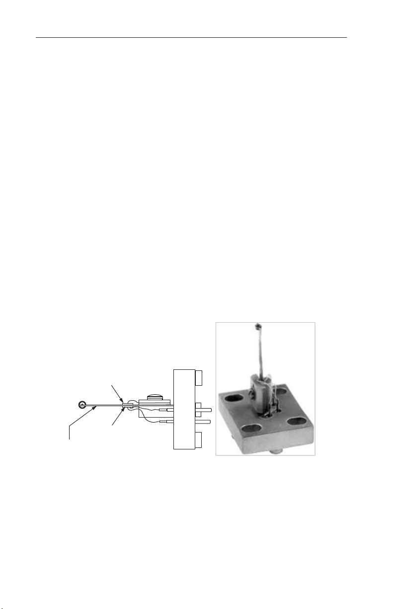
Strain Gage Assembly. The strain gage assembly (Figure 2.2) consists of
a strain gage beam and a glass-to-metal seal feed-through assembly. Strain
gages are bonded to opposite sides of the strain gage beam. The end of the
strain gage beam is installed directly into a cutout in the valve stem connecting the two bellows of the DPU. Any movement of the bellows in either
direction causes a corresponding linear movement of the strain gage beam
which acts upon the strain gages. Any action of the strain gages is monitored
by the electronic transmitter circuit.
Tension Strain Gage
Compression Strain Gage
Range Springs. The range springs act with the bellows to balance the differential pressure applied to the unit. The springs are fabricated of a material that
is compatible with the specic bellows ll uid used. The number of springs
and their rate depends on the differential range desired.
10
Figure 2.2—Strain gage assembly
Page 11

Model 752 and 752A Differential Pressure Transmitters Section 2
Electronic Transmitter
The DPU senses the difference in pressure applied across the bellows unit
assembly and the electronic circuit converts to a 4-20 mA or 10-50 mA output
signal. The pressure causes a linear motion of the bellows which is mechanically transmitted to the strain gages by the strain gage beam. Motion of the
end of the strain gage beam applies tension to one gage and compression on
the other. The gage in tension increases in resistance, while the one under
compression decreases in resistance. The two gages are connected to form
two active arms of a bridge circuit.
Basic Operation
The electronic transmitter is basically a loop current regulating device, where
loop current is controlled by an input of mechanical force or motion. The
block diagram (Figure 2.3, page 12) shows the relationships of the various
stages and the main ow of the electrical currents. As shown, the transmitter,
power supply, and load (line plus receiving device) are connected in series.
The current from the power supply enters the transmitter, passes through the
reverse polarity protecting diode, then divides into two separate paths. The
main current ows through the current amplier stage and returns to the loop.
The remainder of the current passes through the electronic regulator where it
divides into two paths, through the bridge circuit and the voltage amplier.
The current is then returned to the loop. The total loop current ows through
the load and back to the power supply.
Surge Voltage Protection Circuit
Two gas discharge tubes and a Zener diode are placed in the input circuit to
prevent transient voltages from entering the transmitter circuit.
Reverse Polarity Protection
Reverse input polarity protection is provided by the forward-conducting
diode. In the event the polarity of the input is reversed, the diode blocks the
input and prevents the reversed input power from damaging the electronic
circuit components. The diode can accommodate a maximum of 80 Volts
without damage.
Regulator
This stage of the circuit regulates that portion of the loop current which is not
calibrated at the current amplier stage, and provides stabilized voltage for
bridge excitation and power for the signal amplier.
11
Page 12

Section 2 Model 752 and 752A Differential Pressure Transmitters
Figure 2.3—Operational block diagram
Strain Gage Bridge Network
The strain gage bridge network consists of two silicone piezo-resistive strain
sensors, the zero adjusting potentiometer, bridge completion resistors, and the
temperature compensation components.
Signal Amplier
The signal amplier is an integrated circuit operational amplier which provides amplication of the strain gage bridge network output voltage.
Current Amplier
The current amplier circuit converts the signal amplier output voltage to
current. The amount of current is precisely regulated with the feedback network to make it proportional to the bridge output.
Temperature Compensation
The Model 752 and 752A are temperature-compensated at the factory. Only
those repairs described in Section 4 of this manual may be performed in the
eld without voiding the qualications certication.
12
Page 13

Model 752 and 752A Differential Pressure Transmitter Section 3
Section 3—Installation, Startup, and Shutdown
Overview
This section describes the steps required to install the instrument so that it
will perform to its original factory calibration condition. Installation tasks
include
• initial calibration check
• mounting the transmitter
• installing piping
• installing eld wiring
Unpacking/Inspection
The instrument should be inspected at the time of unpacking to detect any
damage that may have occurred during shipment.
IMPORTANT: The unit was checked for accuracy at the factory. Do not change any of
the settings during examination or accuracy will be affected.
The transmitter is shipped in a polyethylene bag to protect the instrument
from contamination. Remove this bag only in a clean area.
Initial Calibration Check
The Model 752 and 752A transmitters are factory-calibrated. However, to
ensure that the calibration is intact following shipping, a calibration check
is recommended prior to operating the instrument. See Calibration, page 19,
for step-by-step instructions. Record the "as found" values and recalibrate, if
necessary.
Mounting
Mount the transmitter so that the pressure housings are in a horizontal position and when the operator is facing the transmitter cover, the controls are on
the right side. Use mounting structures that are designed to minimize vibration and avoid resonance and/or keep resulting amplication below 33 Hz.
Support connected process tubing and conduit using the same mounting as the
instrument base to minimize relative motion of the instrument and connections.
Wall or Rack Mounting
1. Locate and drill four bracket mounting holes in the mounting surface.
2. Attach the instrument to the wall using 5/16" (8 mm) bolts, Grade 5 or
better, and torque to 10-20 ft-lb.
13
Page 14

Section 3 Model 752 and 752A Differential Pressure Transmitters
Piping Guidelines
Observe the following practices when piping for ow and liquid level applications.
1. Install the transmitter as near the primary metering device as possible,
and choose a piping diameter accordingly. For distances up to 50 feet,
use 1/4-inch pipe or tubing. For runs of 50 to 100 feet, use 1/2-inch pipe
or tubing.
IMPORTANT: Distances greater than 100 feet should be used only if an air purge or
blow-back system is installed.
2. Slope all piping at least one inch per linear foot to avoid liquid or gas
entrapment in the lines or the instrument.
• Slope all piping downward from the transmitter when used in gas
applications to prevent liquid entrapment.
• Slope all piping upward from the transmitter when used in liquid ap-
plications to prevent liquid entrapment.
3. If the process temperature exceeds 135ºF, provide a minimum of 2 feet
of uninsulated piping between the transmitter and the primary metering
device for each 100 degrees in excess of +135ºF.
4. Install a suitable pulsation dampening device upstream of the transmitter.
Where severe pulsation is present, the accuracy of the ow measurement
will be affected.
5. For ease of operation and maintenance, install manifolds to allow sensing
lines to be shut off while removing the instrument from the line or performing a calibration. Appendix A shows examples of typical installation
congurations.
6. Locate all shutoff valves and bypass valves so that they are readily accessible from the front of the instrument. Locate block valves at the source
of differential pressure lines.
7. Prevent leakage by using a suitable sealing compound on all joints. Measurement errors can be caused by leaks in the piping.
Electrical Connections
WARNING: Ensure that the condulet cover is secure before applying
!
power to instrument when used in hazardous areas. Failure to do this
may result in personal injury or property damage.
Flexible cable is recommended for electrical connections to the instrument.
14
Page 15
Model 752 and 752A Differential Pressure Transmitter Section 3
+
GND
Receiver
Power Supply
+
+
Junction Box
Load Resistor
Model
752/752A
Perform the following steps to complete eld wiring.
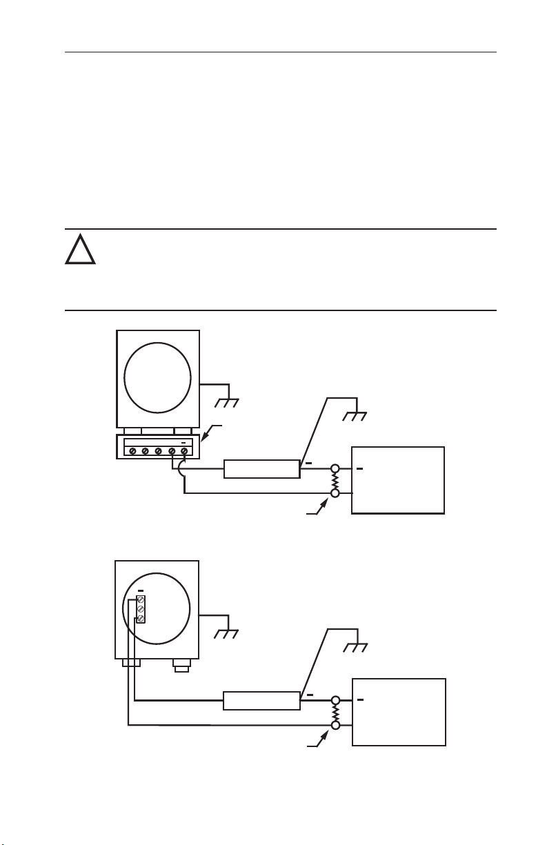
1. Connect the power supply and the receiver to the transmitter as shown in
Figures 3.1 and 3.2.
2. Determine the total loop resistance required for the installation, using
Figure 3.3, page 16, for reference. The total loop resistance must be less
than the maximum calculated value. Table 3.1, page 16, provides loop
resistance values for various cable wire sizes.
3. Install a load resistor sized for the application.
WARNING: Failure to properly calculate power supply DC output voltage
!
may result in inaccurate transmitter readings, possibly leading to safety
system performance degradation during design basis events. To avoid
equipment inaccuracy hazards, follow the examples and tables in this
section for determining the proper power supply DC output voltage.
Figure 3.1—Typical eld wiring connections for Model 752 and 752A with junction box
Model
752 /
752A
+
+
Power Supply
Receiver
+
Figure 3.2—Typical eld wiring connections for Model 752 and 752A without junction
Load Resistor
box
15
Page 16
Section 3 Model 752 and 752A Differential Pressure Transmitters
Power Supply Range (Volts)
Table3.1—CableSpecications
Loop Resistance/1000 ft
Cable Wire Size
(ohms@20°C)
5.06 14 AWG, 2 Wires
8.04 16 AWG, 2 Wires
12.78 18 AWG, 2 Wires
20.30 20 AWG, 2 Wires
1160
70
60
50
40
30
20
10
10-50 mA
200 400 600 800 1000 1200 1400 1600 1800 2000 2200 2400 2600 2800 3000
Total Loop Resistance (Ohms) (Load Transmission Line)
4-20 mA
Any voltage or resistance within the
shaded area for the respective
transmitter output is acceptable.
2900
Figure 3.3—Power supply and loop resistance
Care must be exercised when calculating the power supply output voltage. A
power supply specied as 50Vdc ±1 volt must be considered a 49Vdc source
to ensure the minimum required voltage at the transmitter. Use the actual
value when available; otherwise, use "worst case" value.
Use Figure 3.3 as a reference to determine if the maximum calculated value
of RT = R
Line
+ R
Load
+ R
is correct.
Ext
Loop Resistance Calculations
Use the following method to calculate the loop resistance value.
Total Loop Resistance (RT) = R
Power Supply Voltage = VDC (70 V max. for 4-20 mA or 10-50 mA Systems)
Maximum Transmitter Voltage = T
Minimum Transmitter Voltage = T
Transmitter Current = IDC (20 mA or 50 mA)
16
= VDC - T
R
T
+ R
Line
VDC
VDC
VDC
I
DC
+ R
Load
Ext
(70 V for both 4-20 mA and 10-50 mA Systems)
(12 V for both 4-20 mA and 10-50 mA Systems)
Page 17

Model 752 and 752A Differential Pressure Transmitter Section 3
Maximum Loop Resistance
Example 1: (Maximum loop resistance for 10-50 mA system):
= 70 Vdc T
V
DC
= 50 mA
I
DC
Example 2: (Maximum loop resistance for 4-20 mA system):
= 70 Vdc T
V
DC
= 20 mA
I
DC
Example 3: (Calculation to determine maximum loop resistance with
power supply ≥12 Vdc, but ≤ 70 Vdc for 10-50 mA and 4-20 mA systems):
= 40 Vdc T
V
DC
= 50 mA
I
DC
IDC = 20 mA
= 12 Vdc
VDC
70-12
= = 1160 Ohms
R
T
0.05
= 12 Vdc
VDC
70-12
= = 2,900 Ohms
R
T
0.02
= 12 Vdc
VDC
40-12
= = 560 Ohms
R
T
0.05
40-12
R
= = 1400 Ohms
T
0.02
EMI/RFI Shielding
IMPORTANT: The 752 and 752A transmitters have no integral electronic interference
suppression features. If an instrument is to be installed in an area containing EMI/RFI sources and this interference cannot be tolerated, take
precautions to protect the transmitter signal. An optional EMI/RFI lter is
available upon request. Contact the factory for information.
The following precautions are recommended to limit EMI/RFI interference:
1. Run signal wires in solid conduit or use high quality shielded cable to
connect the transmitter to the power equipment.
2. House the transmitter leads in solid conduit up to the junction box where
the shielded cable is connected to the leads.
3. Ground the electronic transmitter, junction box (including the cover),
conduit, and cable shield.
Startup Procedure
To operate the transmitter, perform the following steps. See the installation
diagrams in Appendix A, page A-1, for typical valve locations.
1. Locate the block valves and make sure they are closed.
NOTE: The block valve is normally installed at the facility for the purpose of iso-
lating the pressure lines (process being monitored) from the monitoring
instruments.
2. Congure the test manifold’s control valves to connect the input pressure
ports of the DPU to the appropriate pressure lines (process being
17
Page 18

Section 3 Model 752 and 752A Differential Pressure Transmitters
monitored). Follow the guidelines in Appendix A that are specic to your
piping conguration.
3. Open the block valves if applicable (recommended for liquid service, but
not for gas).
NOTE: For gas service, it is recommended that a zero check be performed with
both block valves closed. If the gas ow is pulsating, there may be a
standing wave effect in the process line which can displace the indicator
and appear as a zero error.
4. Apply electrical power to the transmitter loop.
5. Check the transmitter calibration across all checkpoints, using the
instructions provided in Calibration, page 19. If re-adjustment of the zero
and/or span is necessary, perform all 12 steps described in the Calibration
Procedure, page 21.
6. Check the manifold and piping for leaks as follows:
a. Open the bypass valve(s), then open one shutoff valve to pressurize
the instrument.
b. Close the shutoff valve and the bypass valve.
c. Any leakage will be indicated by a change (increase or decrease) in
the transmitter output.
NOTE: Be careful not to subject the DPU to unnecessary shock or overrange
pressure during operations.
Shutdown Procedure
To shut down operations, perform the following steps. See the installation
diagrams in Appendix A, page A-1, for typical valve locations.
1. Remove electrical power from the transmitter loop.
2. Close the transmitter shut-off valves.
3. Close the main block valves at the process connections.
4. Open the transmitter drain valves and remove all pressure from the unit.
18
Page 19

Model 752 and 752A Differential Pressure Transmitters Section 4
Section 4—Calibration and Maintenance
General Field and Periodic Maintenance
Electronic Transmitter
The electronic transmitter circuits are basically maintenance-free and do not
require routine preventative maintenance other than a periodic check of calibration. See Calibration below for details.
Differential Pressure Unit (DPU)
The eld maintenance schedule for the DPU will depend on the purpose for
which it is used. Periodic cleaning of the DPU is required if the instrument
is used in a system where solids or semi-solids can accumulate in the DPU
housings. Follow the guidelines in DPU Inspection and Cleaning, page 22, and
take the necessary safety precautions to avoid damage to the bellows.
Calibration
Each transmitter is calibrated at the factory prior to shipment. A 9-point calibration check is recommended upon receipt, and again before the transmitter
is operated for the rst time. If "as found" values are not within the specied
range, a full calibration should be performed.
The transmitter should be recalibrated at periodic intervals, determined
primarily by the usage of the transmitter, historical performance, the desired
accuracy of the output signal, or indications that the instrument may be out of
calibration. If a transmitter is installed after an extended period of storage, a
calibration test should be performed before operating the transmitter to ensure
correct performance.
Test Equipment
To perform the calibration procedure for an instrument with 0.5% accuracy,
the test equipment should meet or exceed the requirements listed in Table 4.1,
page 20. For calibrating instruments, the pressure source should have at least 4
times the accuracy of the instrument being tested. In the event equipment is
substituted that does not meet these requirements, the accuracy of the recalibrated transmitter must be derated accordingly.
19
Page 20
Section 4 Model 752 and 752A Differential Pressure Transmitters
Table 4.1—Calibration Equipment
Equipment Requirements
Digital Voltmeter ±0.05% of reading accuracy at 10 VDC scale
Power Supply 12-70 Vdc, 60 mA minimum, regulation 3%, ripple 1% (see Electrical
Precision Load Resistor 200 ohms, ±0.05%, 1W (10-50 mA transmitter) 500 ohms, ±0.05%,
Pressure Source Provides zero to full scale pressure (Accuracy: 4 times the accuracy
Connections, page 14)
1W (4-20 mA transmitter)
of the instrument under test)
Electrical Connections for Calibration
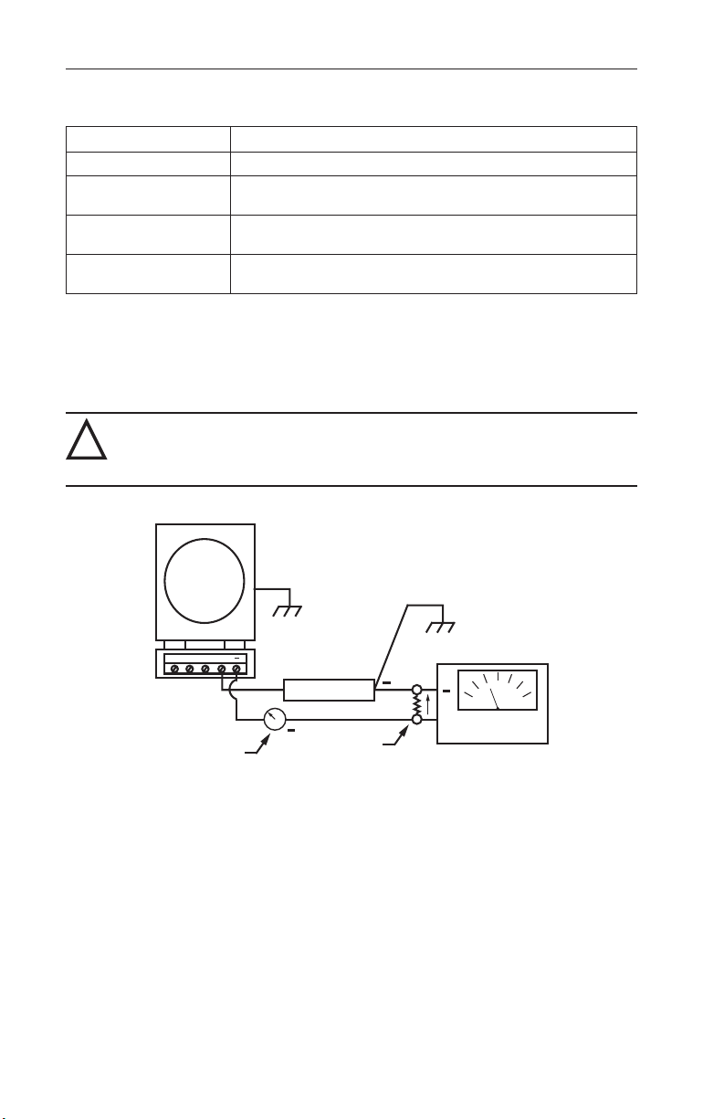
The electrical connections required for calibrating the transmitter are shown
in Figure 4.1.
WARNING: Ensure that the condulet cover is secure before applying
!
power to instrument when used in hazardous areas. Failure to do this
may result in personal injury or property damage.
Model
752/752A
GND
+
+
Power Supply
Precision
+
Milliammeter
(optional)
Figure 4.1—Electrical connections for calibration
Load
Resistor
500 ohms, 4-20 mA systems
200 ohms, 10-50 mA systems
+
DC Voltmeter
Flexible cable is recommended for electrical connections to the instrument.
Perform the following steps to complete eld wiring.
1. Connect the power supply and the DC voltmeter to the transmitter as
shown in Figure 4.1.
2. Connect a milliammeter as shown, if desired.
3. Determine the total loop resistance required for the installation, using
Figure 3.3, page 16, for reference. The total loop resistance must be less
than the maximum calculated value. Table 3.1, page 16, provides loop
resistance values for various cable wire sizes.
20
Page 21

Model 752 and 752A Differential Pressure Transmitters Section 4
4. Install a load resistor sized for the application.
WARNING: Failure to properly calculate power supply DC output voltage
!
may result in inaccurate transmitter readings, possibly leading to safety
system performance degradation during design basis events. To avoid
equipment inaccuracy hazards, follow the examples and tables in this
section for determining the proper power supply DC output voltage.
Calibration Checkpoints
Table 4.2 presents the transmitter output values in current and voltage, along
with the associated tolerance for instrument with 0.5% accuracy, for both the
4-20 mA and 10-50 mA variations. Instruments are held to the same toler-
ances during factory calibration. For calibrating instruments with 0.25%
accuracy, divide the tolerances shown by one-half.
Table 4.2—Calibration Checkpoints for Instrument with 0.5% Accuracy
Voltage
Output*
Current
(±0.2mA)
Voltage
(±0.04Vdc)
Applied Calibration
Pressure Checkpoint
(%ofSpan)
0% 4 mA 2 Vdc 10 mA 2 Vdc
25% 8 mA 4 Vdc 20 mA 4 Vdc
50% 12 mA 6 Vdc 30 mA 6 Vdc
75% 16 mA 8 Vdc 40 mA 8 Vdc
100% 20 mA 10 Vdc 50 mA 10 Vdc
*This value includes the effects of conformance (non-linearity), deadband, hysteresis, and repeatability.
**This value was obtained using a 500-ohms load resistor.
***This value was obtained using a 200-ohms load resistor.
4-20 mA Transmitter** 10-50 mA Transmitter***
Current
(±0.08mA)
(±0.04Vdc)
Calibration Procedure
The following procedure can be used to obtain "as found" calibration values
or perform a full calibration.
• To obtain the “as found” calibration values (calibration check only),
perform steps 1 through 6 and steps 10 through 12, skipping steps 7
through 9.
• For periodic calibration or in cases where the “as found” calibration
values do not meet the tolerances specied in Table 4.2, perform all
12 steps.
1. Verify that the transmitter is installed in accordance with the mounting
guidelines on, page 13 and the piping guidelines on page 14.
2. Locate the block valves and make sure they are closed. The block valves
are normally installed at the facility for the purpose of isolating the pro-
21
Page 22

Section 4 Model 752 and 752A Differential Pressure Transmitters
cess being monitored from the monitoring instruments.
3. Congure the test manifold control valve to connect the output of the test
pressure source to the high port of the DPU and vent the low side of the
DPU to atmosphere.
4. Verify that all electrical connections are properly installed (see electrical
connections in Figure 3.1, page 15.
5. Apply the appropriate power supply voltage to the transmitter. (To determine this voltage, see Power Supply, page 4.)
6. Exercise the transmitter by applying 0% and 100% calibration pressures
(specied in Table 4.2, page 21) three times. If performing a calibration
check only, proceed to step 10.
7. Apply the calibration pressure for the 0% checkpoint (as specied in
Table 4.2, page 21). Adjust the zero control potentiometer as required to
produce the recommended output level.
8. Apply the calibration pressure for the 100% checkpoint (as specied in
Table 4.2, page 21). Adjust the span control potentiometer as required to
produce the recommended output level.
9. Repeat steps 7 and 8 until no further renements can be made.
10. Apply the calibration pressures referred to in Table 4.2, page 21, starting
from 0% to 100%, and record the applied pressures and the output levels
at each measurement.
11. Repeat the calibration checks in descending order, from 75% to 0%, and
record the applied pressures and the output levels at each measurement.
12. Repeat steps 10 and 11 until you have completed three consecutive runs
and have recorded all relevant data.
Note: If correct readings cannot be obtained, refer to the troubleshooting sug-
gestions in Tables 4.3 and 4.4, or return the unit to the manufacturer for
repair and calibration.
DPU Inspection and Cleaning
To inspect and clean the DPU, perform the following steps.
1. Remove the instrument from service and remove pressure housing bolts.
2. Carefully remove the pressure housings.
Note: If accumulation of material is extensive, rapid removal of the housings
may damage the bellows convolutions.
3. Remove accumulation from between bellows convolutions and housings
using a solvent, if possible.
Note: Do not use sharp instrument to clean between bellows convolutions.
22
Page 23

Model 752 and 752A Differential Pressure Transmitters Section 4
4. Replace the housings (new O-rings are recommended) and 3/8" CRES
head bolts.
5. Apply Molycoat G paste or similar lubricant to threads and under heads
(bearing surface) of bolts. Do not use silicone oil or grease.
6. Torque the head bolts to 45 ft-lb to a rotation of up to 135 degrees nominal using a torque wrench. The rotation of the bolt is measured after the
bolt is "snug" with approximately 2 ft-lb torque.
Note: Do not exceed the specied rotation. If a bolt fails to reach the specied
torque within the rotation limit, reject the bolt.
Troubleshooting
Refer to Tables 4.3 and 4.4, pages 21 through 23, for troubleshooting information and Section 5 for part location.
Note: If the sensor assembly is determined to be faulty, the transmitter should
Problem Possible
Low or No
Output
be returned to the factory for repair or replacement.
Table 4.3—DPU Troubleshooting
Source
Primary
Element or
DP Source
Piping from
Primary
Element to
Transmitter
Bellows Unit Housing lled with solids restrict-
Orice installed backwards or
oversized;
Flow blocked upstream from run;
Density changes in process
media or ref. leg
Pressure tap holes or piping
plugged;
Bypass valve open or leaks;
Liquids or gases trapped in pipe;
Block or shutoff valves closed;
Piping leaks, high pressure side
ing bellows movement;
Gas trapped in housing in liquid
service or liquid trapped in housing in gas service;
HP housing gasket leaks;
Body tampered with
Probable Cause Corrective Action
Replace orice;
Clean out run or
open valve;
Rell reference leg
with same density
liquid as process
Clean out piping;
Close bypass valve;
Vent piping;
Open block or shutoff valves;
Repair leaks
Clean out housing;
Vent housing;
Replace gasket;
Return unit for
repair
23
Page 24

Section 4 Model 752 and 752A Differential Pressure Transmitters
Table 4.3—DPU Troubleshooting
Problem Possible
High
Output
Source
Primary
Element
Orice partially restricted or too
small;
Loss of liquid in reference leg
Probable Cause Corrective Action
Clean out or
replace;
Rell reference leg
(liquid level)
Piping from
Leak in LP side piping Repair
Primary
Element to
Transmitter
Bellows Unit Gas trapped in LP housing in
liquid service or liquid trapped in
gas service;
LP housing gasket leaks;
Vent housing;
Replace gasket;
Return unit for
repair
Range spring broken or body
tampered with
Erratic or
Intermittent
Operation
Primary
Flow pulsating Install dampening
Element
Piping from
Primary
Element to
Transmitter
Liquid trapped in gas piping or
gas bubble in liquid piping;
Vapor generator installed wrong;
Reference leg gassy or liquid
vaporizing
Bellows Unit Obstructed bellows travel;
Gas trapped in HP or LP housing
device upstream of
meter run
Remove trapped
liquid or gas bubble;
Repipe;
See piping instruc-
tions
See DPU Inspec-
tion and Cleaning,
page 22.
Remove trapped
gas
Out of
Calibration
Bellows Unit Dirt in bellows;
Damaged bellows
Clean external
bellows surface or
return damaged
DPU for repair
24
Page 25

Model 752 and 752A Differential Pressure Transmitters Section 4
Table 4.4—Transmitter Troubleshooting
Problem Possible
Source
No Output Power
Source
Transmission
Cable
Blown fuse, faulty
component
Loose terminal connection Tighten terminal
Probable Cause Corrective Action
Replace fuse, repair
power supply
connection; locate
and replace broken
wire
Receiver
(or load)
Blown fuse, faulty component Replace fuse; repair
or replace receiver
or load
Transmitter Loose terminal, reversed power
connection, faulty component
Tighten terminal,
reverse power connection, return to
factory for repair
Transmitter
"zeros" but
cannot get
full output
Power
Source
Load
Resistance
Low voltage Repair power
source
Resistance too high Replace load resis-
tance or repair as
required
Transmission
Cable
Electronic
Module
Resistance or length of cable in
excess of
specications
Measure cable loop
resistance and bring
within specications
Loss of gain Return to factory for
repair.
Amplier
Out of
Calibration
Erratic or
Intermittent
Operation
Electronic Component value shifted Recalibrate or return
to factory for repair
Terminal
Connections
Electronic
Component
Loose or dirty Tighten and/or clean
as required
Defective component Return to factory for
repair
Strain Gages Physical damage Return to factory for
repair
Excess
Output (will
Transmitter Defective component Return to factory for
repair
not "zero")
25
Page 26

Section 4 Model 752 and 752A Differential Pressure Transmitters
26
Page 27
Model 752 and 752A Differential Pressure Transmitters Section 5
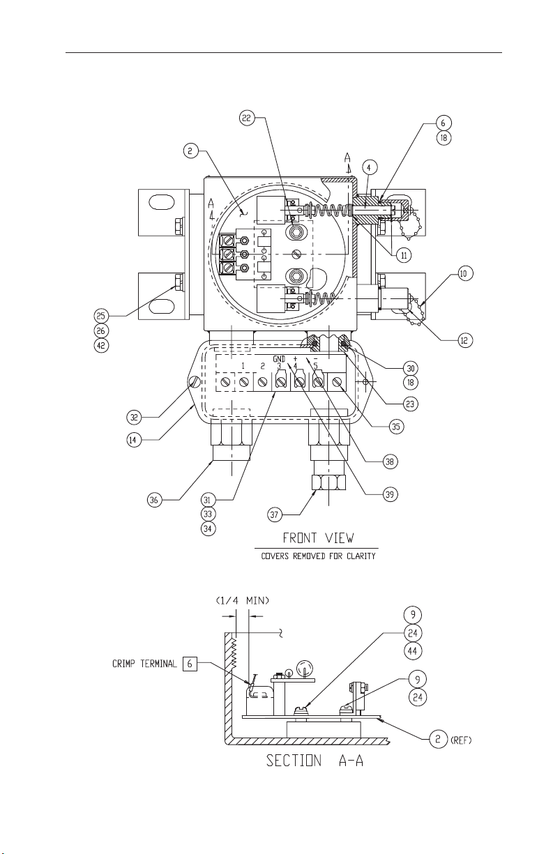
Section 5—Assembly Drawing and Parts List
Figure 5.1—Model 752 and 752A, front view
27
Page 28
Section 5 Model 752 and 752A Differential Pressure Transmitters
43
WARNING:Itemsmarkedwithanasterisk(*)belowmaybereplacedwith-
!
outlossofinstrumentqualication.Noothereldrepairsorcomponent
replacementsareauthorizedifinstrumentqualicationistobemain-
tained.
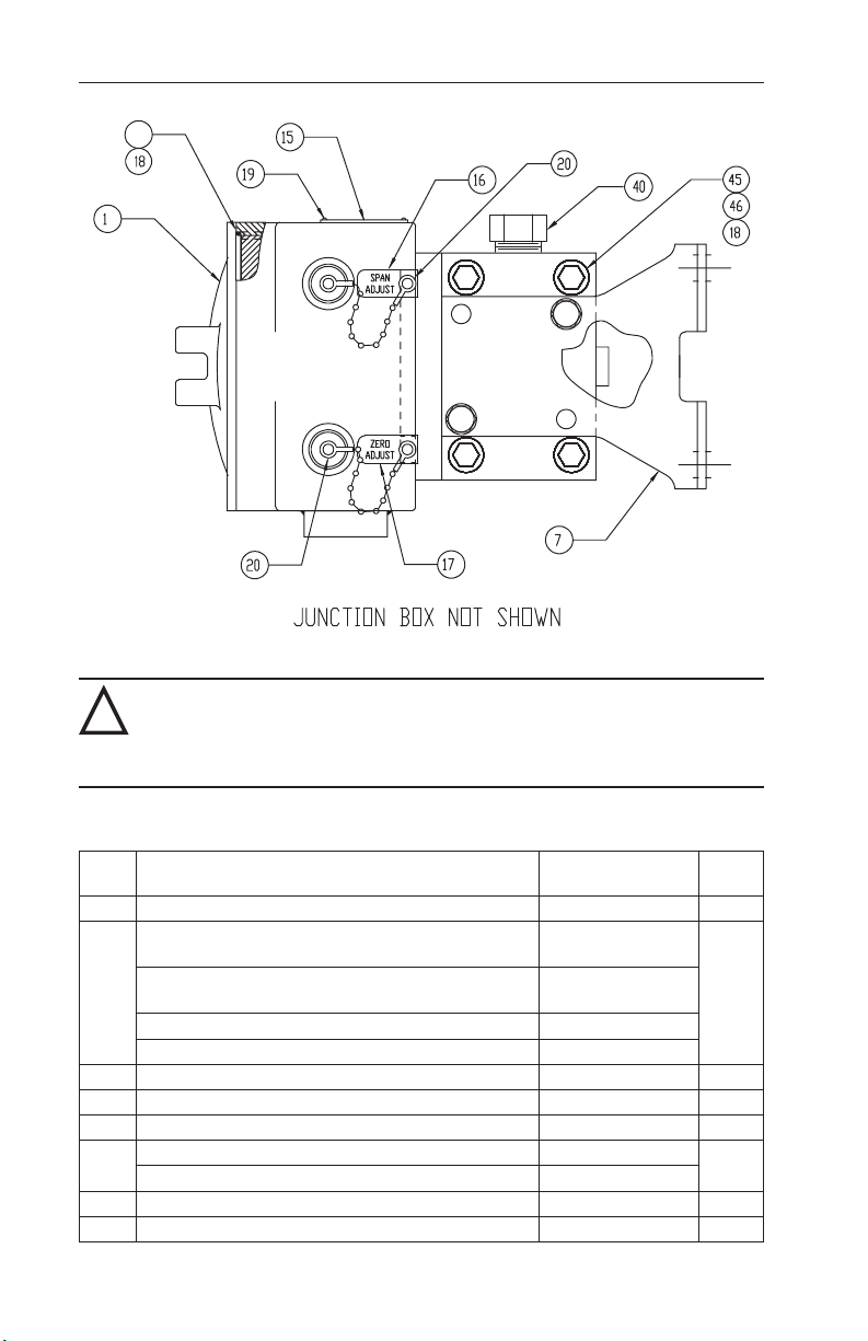
Table 5.1—752 and 752A Parts List
ITEM DESCRIPTION PART NO.
1* Enclosure cover (gray) 9A-C0039-1045C 1
Model 752 circuit board assembly, 4 to 20 mA
(replacements no longer available)
Model 752 circuit board assembly, 10 to 50 mA
2
(replacements no longer available)
Model 752A circuit board assembly, 4 to 20 mA 9A-C0752-1269B
Model 752A circuit board assembly, 10 to 50 mA 9A-C0752-1270B
4* Shaft and spring assembly 9A-C0752-1100B 2
6* O-ring, EPT, E740-75, 3/8 x 1/2 9A-C0001-1051R 2
7* Mounting bracket 9A-C0273-0001C 2
Pan head screw, 6-32 x 3/16, Model 752 9A-C0119-1006J
9
Pan head screw, 6-32 x 1/4, Model 752A 9A-C0119-0016J
10* Bead chain 9A-C0076-0007T 2
11* Retaining ring 9A-C0087-0040T 4
28
9A-C0752-1056B
9A-C0752-1070B
PER
UNIT
1
2
Page 29

Model 752 and 752A Differential Pressure Transmitters Section 5
Table 5.1—752 and 752A Parts List
ITEM DESCRIPTION PART NO.
12* Cap 9A-C0752-1004C 2
14* Junction box 9A-C0752-1114C 1
15 Data plate 9C-C0752-1172G 1
16 I.D. plate, span adjust 9A-C0752-1121C 1
17 I.D. plate, zero adjust 9A-C0752-1122C 1
18* Silicone grease 9A-C0002-1003U A/R
Drive screw, 00 9A-C0600-1001J
19
20 Drive screw, #2 9C-C0600-1004J 4
23* Adapter 9A-C0752-1111C 2
24 Lock washer, #6 9A-C0003-0070K 2
Lock washer, 1/4 9A-C0003-0037K
25*
Flat washer, 1/4 9A-C0003-1049K
26*
29 Tag (not shown) 9A-C0199-0125C 1
30* O-ring, EPT, E740-75, 11/16 x 13/16 9A-C0001-1130R 2
31* Terminal bracket 9A-C0752-1112C 1
32* Pan head screw, 8-32 x 1/4 SST 9A-C0119-0006J 2
Marker strip 9A-C0752-1113C
33*
34* Terminal block 9A-C0038-1170T 1
35* Pan head screw, 8-32 x 1/2 SST 9A-C0119-0005J 2
36* Conduit hub 9A-C0024-1006T 2
37* Drain plug 9A-C0186-0001T 1
38* Wire assembly, black 9A-C0752-1120B 1
Wire assembly, red 9A-C0752-1119B
39*
40* Port plug, 1/2-in. NPT 9A-C0199-0215C 2
41 DC-550 silicone oil 9A-C0003-1002U A/R
42* Hex head bolt, 1/4-28 x 5/8 (8 ft-lb Torque) 9A-C0116-1007J 4
43* O-ring, cover, EPT 9A-C0001-1105R 1
44 Washer, at, #6, SST
45* Housing O-ring, EPT, E740-75, 1-3/4 X 1-7/8
46* Housing, 1/2 × 1/4 NPT Ports
Housing Cap Screws; 3/8-24×1-1/2 SST (40 ft-lb
47*
Torque)
9A-C0003-0040K
9A-C0001-1054R
9A-C0764-1025C
9A-C0220-1028J
PER
UNIT
4
8
8
1
1
1
2
2
8
29
Page 30

Section 5 Model 752 and 752A Differential Pressure Transmitters
30
Page 31
Model 752 and 752A Differential Pressure Transmitters Section 6
Section 6—Dimensional Drawings
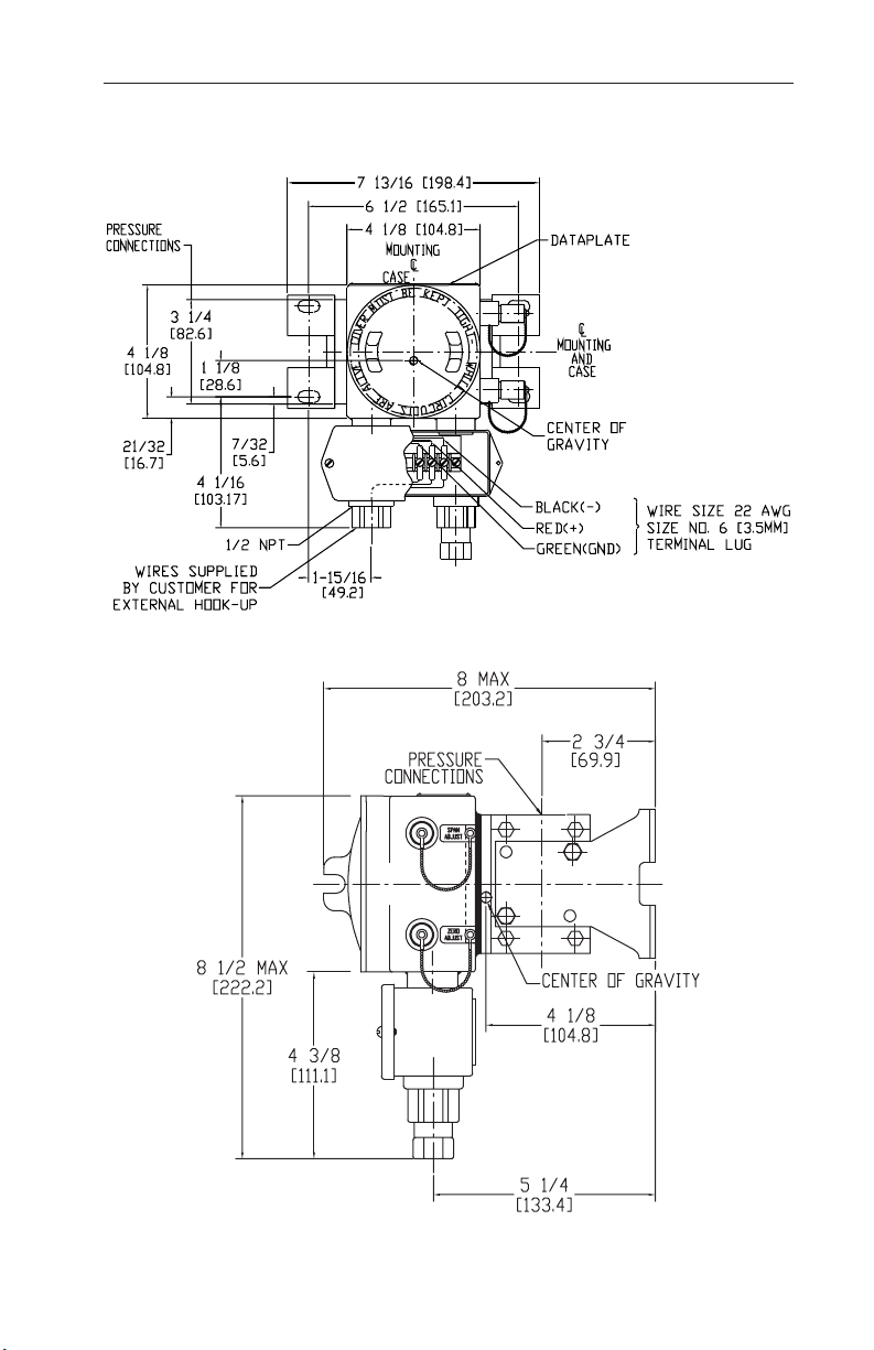
Figure 6.1—Model 752 and 752A transmitters with junction box, front view
Figure 6.2—Model 752 and 752A transmitters with junction box, side view
31
Page 32
Section 6 Model 752 and 752A Differential Pressure Transmitters
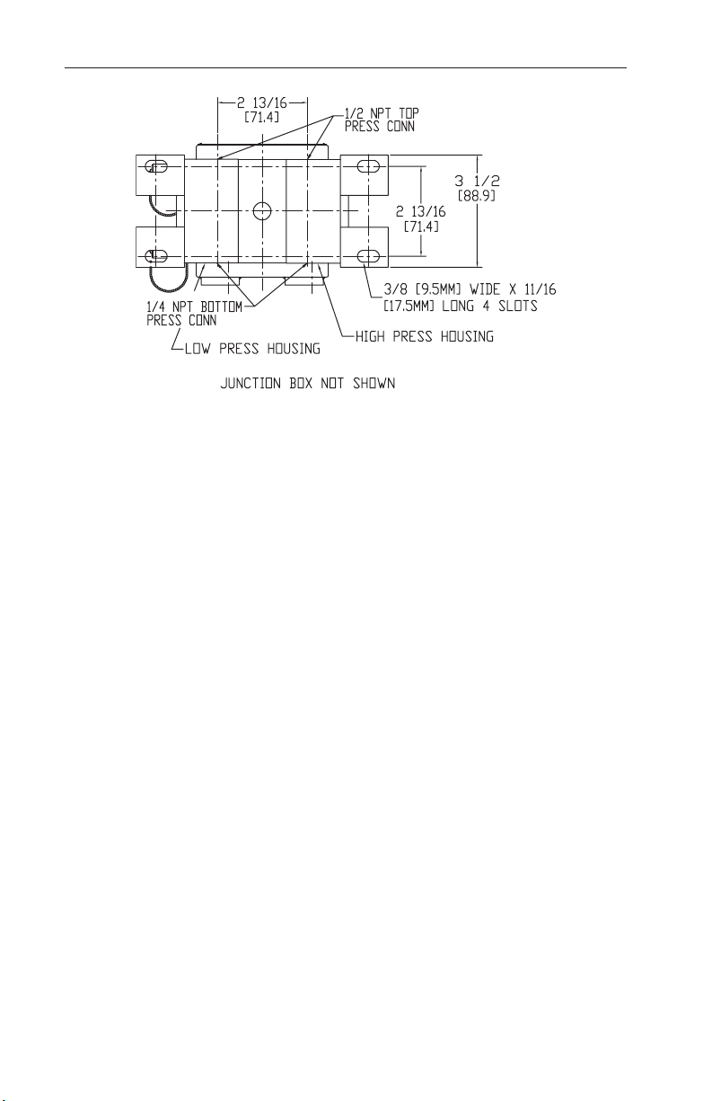
Figure 6.3—Model 752 and 752A transmitters, rear view
32
Page 33

Model 752 and 752A Differential Pressure Transmitters Appendix A
Appendix A
Safety Precautions
Suggested piping diagrams and startup instructions for typical and special
ow applications are presented on the following pages.
WARNING HIGH-PRESSURE HAZARD. TO PREVENT PERSONAL INJURY
WARNING EXPLOSION HAZARD. NO ORGANIC COMPOUNDS, OIL, GREASE,
OR DAMAGE TO EQUIPMENT, DIRECT ALL PIPING AWAY FROM
THE OPERATOR WHILE CONNECTING THE DPU TO THE SYSTEM
PIPING.
DIRT, OR SCALE OF ANY KIND CAN BE TOLERATED IN AN
OXYGEN INSTALLATION.
Flow Application
Important: Assure that the DPU high-pressure housing is connected to the upstream
Note: To prevent overheating the DPU during blowdown, monitor the tem-
tap of the primary device.
perature by placing your hands on the pipe between the DPU and the
manifold pipe containing the vent valves.
Liquid Level Applications
The process media may be used as a reference leg seal uid when it is of a
type that will condense in the reference leg under all conditions. If the process
or process media characteristics are such that the above conditions cannot be
met, a special reference leg seal uid will be required.
The special seal uid must not be volatile and must not be miscible with the
process media. Also, the difference in the densities of the special seal uid
and the process media will require compensation in calculating the differential pressure range of the DPU.
A-1
Page 34
Appendix A Model 752 and 752A Differential Pressure Transmitters
STATIC PRESSURE
BYPASS
SHUT-OFF
Typical Piping/Startup Examples
Diagrams for typical and special ow applications are presented on the following pages. Use the diagram best suited for the application as a guide for
piping conguration.
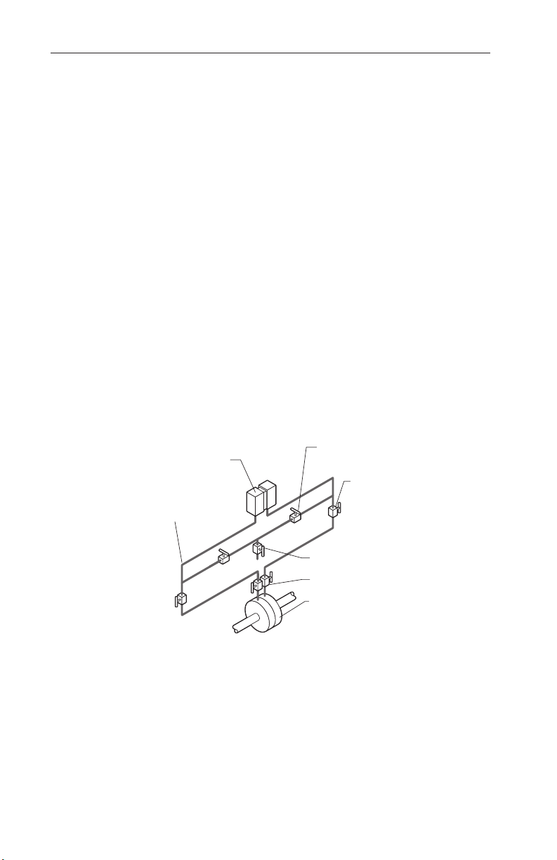
Gas Flow, DPU Above Run
The following steps are recommended for applications in which hydrates are
NOT present.
1. Open the bypass valve(s) and close the vent valve.
2. Open both shutoff valves and one block valve to pressurize DPU, then
close the block valve.
3. Close one bypass valve and check the system for leaks. If output travels
upscale, check for low-pressure piping leaks. If output travels downscale,
check for high-pressure piping leaks.
4. Repair piping if necessary and repeat steps 1 through 3 until output
remains stable at zero.
5. Close both shutoff valves and open the bypass valve(s).
6. Open both block valves and slowly open both shutoff valves.
7. Close the bypass valves, and if two bypass valves are used, open the vent
valve.
A-2
DPU
CONNECTION
(USE ONLY ONE)
Figure A.1—Gas Flow, DPU Above Run
VALVES
VALVES
VENT VALVE
BLOCK VALVES
PRIMARY DEVICE
Page 35
Model 752 and 752A Differential Pressure Transmitters Appendix A
BLOCK
STATIC PRESSURE
SHUT-OFF
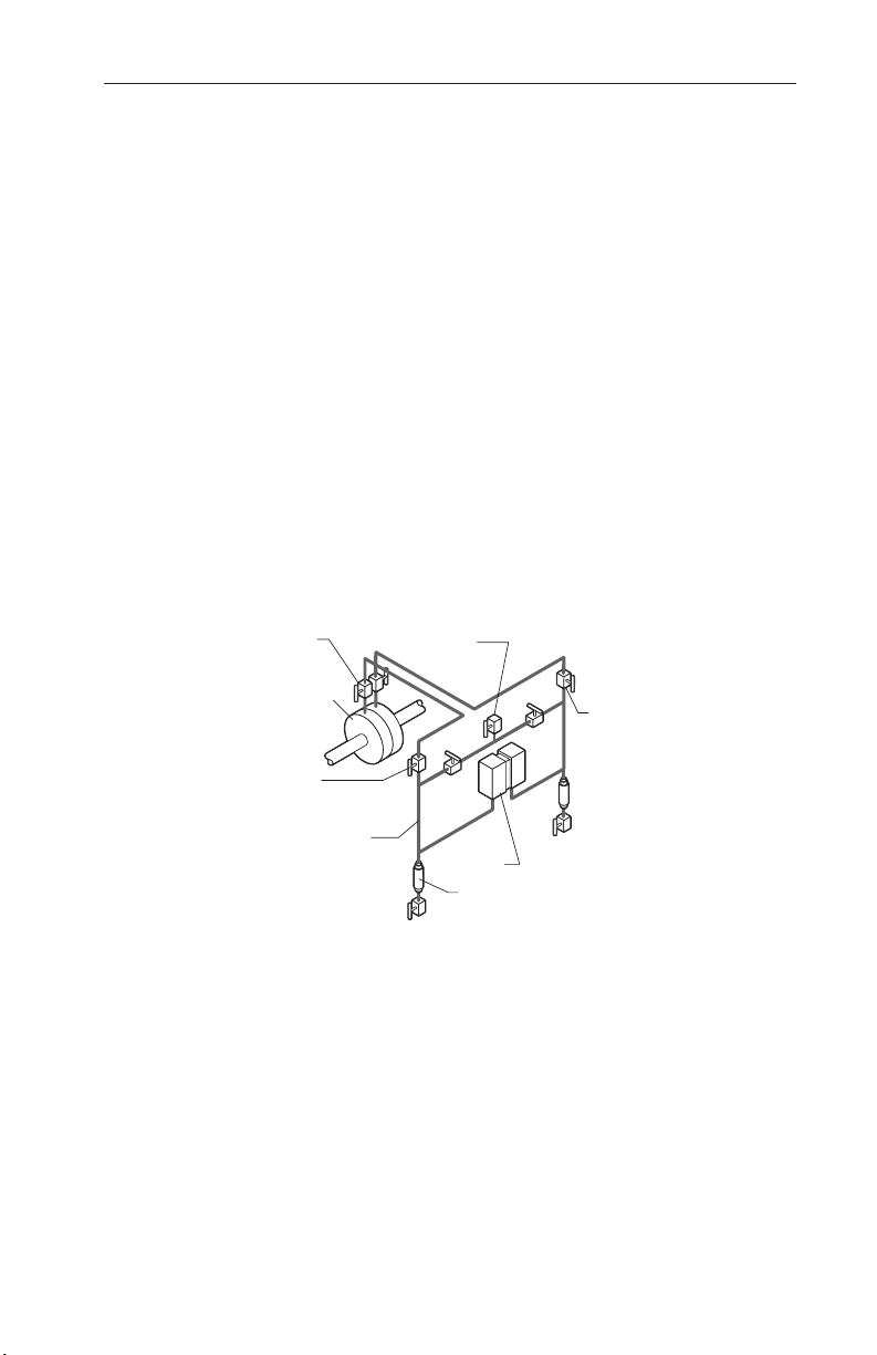
Gas Flow, DPU Below Run
The following steps are recommended only for applications that require the
DPU to be mounted below the run. Drip pots are required when wet gas is
present.
1. Open the bypass valve(s) and close the vent valve.
2. Open both shutoff valves and one block valve to pressurize DPU, then
close the block valve.
3. Close one bypass valve and check the system for leaks. If output travels
upscale, check for low-pressure piping leaks. If output travels downscale,
check for high-pressure piping leaks.
4. Repair piping if necessary and repeat steps 1 through 3 until output
remains stable at zero.
5. Close both shutoff valves and open the bypass valve(s).
6. Open both block valves and slowly open both shutoff valves.
7. Close the bypass valves, and if two bypass valves are used, open the vent
valve.
8. If drip pots are used, open the drip valves and blow out accumulated
liquid.
VENT
VALVE
VALVES
PRIMARY
DEVICE
BYPASS
VALVES
CONNECTION
(USE ONLY ONE)
Figure A.2—Gas Flow, DPU Below Run
VALVES
DPU
DRIP POTS
A-3
Page 36
Appendix A Model 752 and 752A Differential Pressure Transmitters
PRIMARY DEVICE
STATIC PRESSURE
VENT
SHUT-OFF
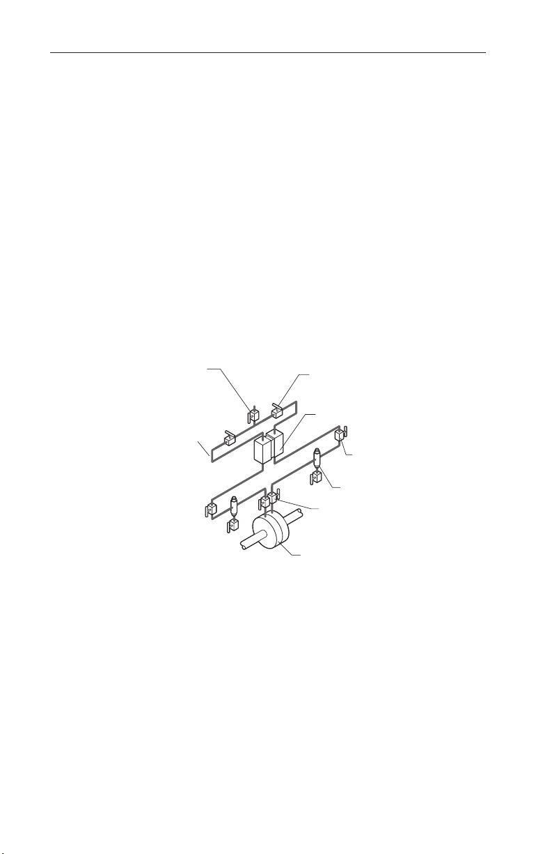
Gas Flow, Hydrates Present
The following steps are recommended for applications in which hydrates
or heavy solids are present, and piping and shutoff valves are not less than
1/2-inch in diameter. Bypass the manifold above to isolate the meter from
connecting piping. Drip pots prevent plugging.
1. Open the bypass valve(s) and close the vent valve.
2. Open both shutoff valves and one block valve to pressurize the DPU,
then close the block valve.
3. Close one bypass valve and check the system for leaks. If output travels
upscale, check for low-pressure piping leaks. If output travels downscale, check for high-pressure piping leaks.
4. Repair piping if necessary and repeat steps 1 through 3 until output
remains stable at zero.
5. Close the bypass valves. If two bypass valves are used, open the vent
valve.
6. Drain the drip pots of hydrates at regular intervals.
VALVE
CONNECTION
(USE ONLY ONE)
Figure A.3—Gas Flow, Hydrates Present
BYPASS
VALVES
DPU
BLOCK
VALVES
VALVES
DRIP POTS
A-4
Page 37
Model 752 and 752A Differential Pressure Transmitters Appendix A
PLUGS
BLOCK
VALVES
CONDENSING
RESERVOIR
PRIMARY
SHUT-OFF
VALVES
VENT
VALVES
(OPTIONAL)
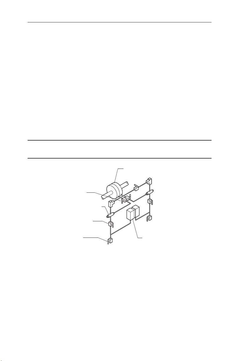
Steam Flow, DPU Below Run
For this application, condensing reservoirs and piping to orice taps must be
level. Assure that the reservoir and steam lines are at the same level. Two-inch
pipe crosses may be used as seal pots.
1. Close the vent valves, if used, and open the bypass and shutoff valves.
2. Remove the condensing reservoir side and ll plugs.
3. Pour water into both reservoirs until the piping and the DPU housings are
lled. Piping and housing chambers shall be free of bubbles. The pointer
should rest at zero (or output will be 4 mA or 10 mA as applicable) when
the instrument and piping are completely lled.
4. Install the side and ll plugs in the reservoirs.
5. Close the shutoff valves and open the block valves.
6. Slowly open both shutoff valves simultaneously and check for leaks.
7. Close the bypass valve.
NOTE: Assure that plugs are used on the DPU. Valves should never be used on
the DPU.
DEVICE
DPU
Figure A.4—Steam Flow, DPU Below Run
A-5
Page 38
Appendix A Model 752 and 752A Differential Pressure Transmitters
BLOCK VALVES
PRIMARY
DEVICE
SHUT-OFF
DPU
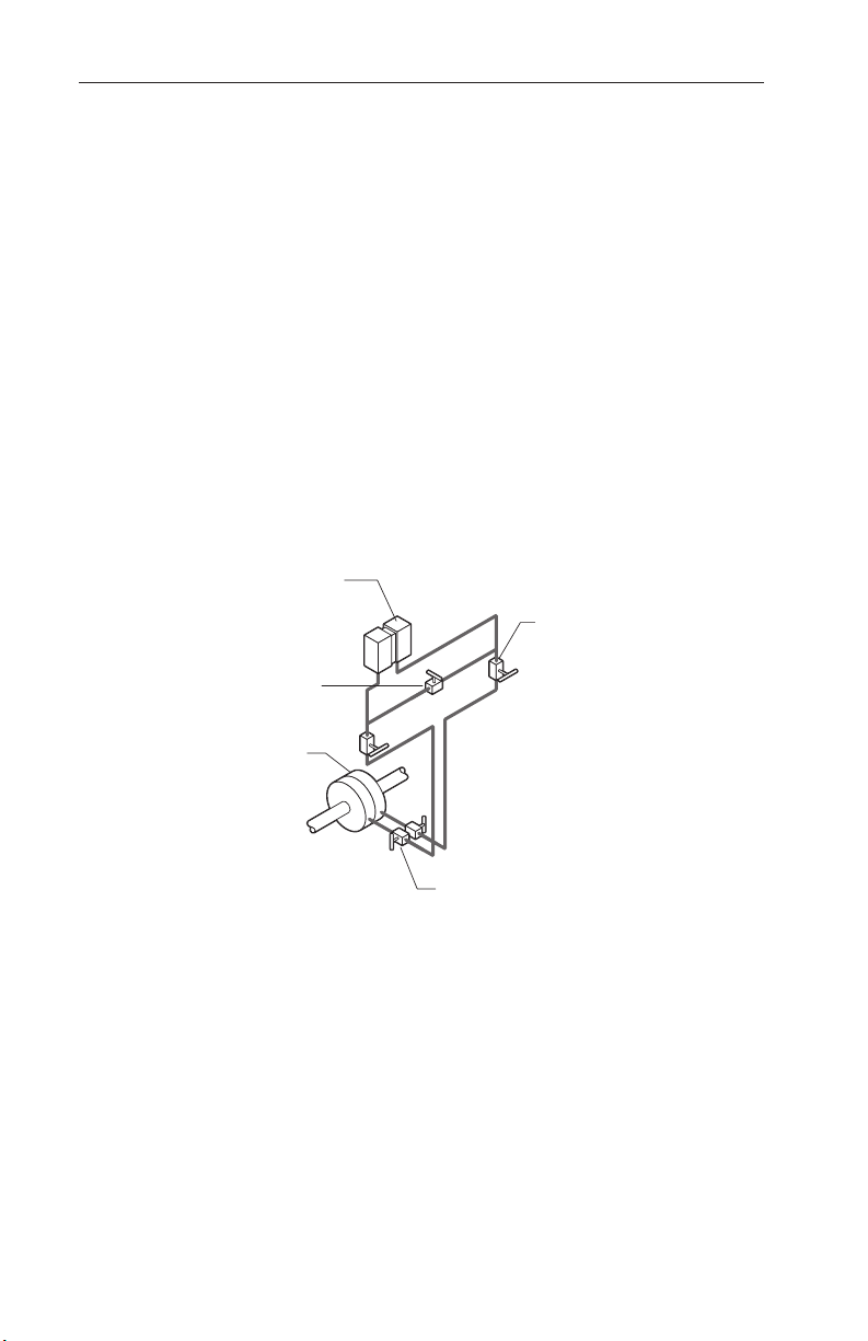
Liquid Flow, DPU Above Run
The following steps are recommended for applications in which sediments
may be present. Inspect piping periodically. Not recommended for hot or
gassy liquids.
1. Close both shutoff valves and open both block valves.
2. Open the bypass valve. Crack the vent valves or loosen the plugs from
the top ports of the DPU body housings.
3. Crack and close the shutoff valves alternately until liquid is free of
bubbles and spills out of both upper DPU body ports.
4. Close the vent valves or tighten the plugs. Close the block valves and
open the shutoff valves.
5. The pointer should rest at zero (or output will be 4 mA or 10 mA as ap-
plicable). If it does not and no leaks are detected, the housing and/or pip-
ing are not completely lled with liquid. Repeat steps 1 through 4 until
output remains stable at the lowest value.
6. Slowly open both block valves and close the bypass valve.
VALVES
BYPASS
VALVE
Figure A.5— Liquid Flow, DPU Above Run
A-6
Page 39
Model 752 and 752A Differential Pressure Transmitters Appendix A
PRIMARY
GASSY LIQUIDS
SHUT-OFF
VALVES
DPU
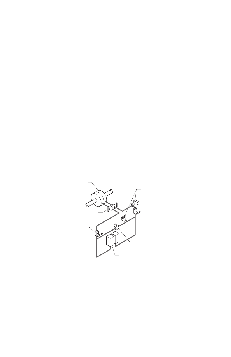
Liquid Flow, DPU Below Run
The following steps are recommended for hot or gassy liquids. Periodic inspections of piping are recommended.
1. Close both shutoff valves and open both block valves.
2. Open the bypass valve. Crack the vent valves or loosen the plugs from
the top ports of the DPU pressure housings.
3. Crack and close the shutoff valves alternately until the liquid is free of
bubbles and spills out of both upper DPU body ports.
4. Close the vent valves or tighten the plugs. Close the block valves and
open the shutoff valves.
5. The pointer should rest at zero (or output will be 4 mA or 10 mA as ap-
plicable). If it does not and no leaks are detected, the housing and/or pip-
ing are not completely lled with liquid. Repeat steps 1 through 4 until
the output is stable at the lowest value.
6. Slowly open both bl ock valves and close the bypass valve.
7. For service with hot or gassy liquids, ll both sides of the manifold
through the ll tee, with the liquid to be measured cooled to +200°F
(+93.3°C) or less, and expel gas bubbles from DPU and piping.
8. Open the vent valve and the bypass valve. Tighten the ll plug when
bubble-free liquid ows.
DEVICE
BLOCK
VALVES
Figure A.6—Liquid Flow, DPU Below Run
FILL TEE AND
VENT VALVE
FOR HOT OR
BYPASS
VALVE
A-7
Page 40
Appendix A Model 752 and 752A Differential Pressure Transmitters
HIGH-PRESSURE
2" CROSS
VALVE
SHUT-OFF
VALVE
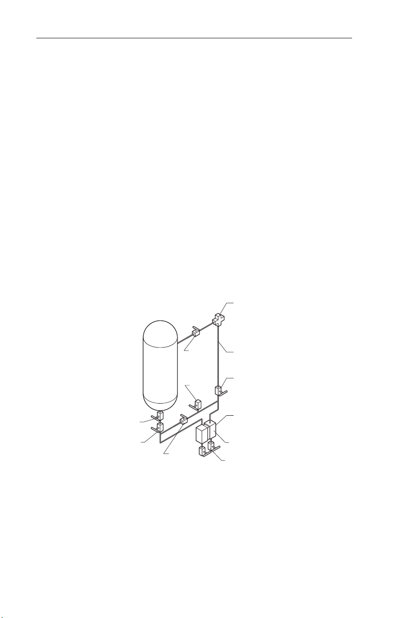
DPU Below Tank with Reference Leg: Hot or Cool Liquids
The use of a reference leg cancels out the "dead leg" (piping from the tank
bottom to center line of meter body). Seal uid in the reference leg must not
volatilize. Process media can be used as a reference leg seal uid if it will
condense in the reference leg under all conditions. Otherwise, special, immiscible seal uid must be used. Differences in densities of process media and
seal uid must be considered when computing the differential pressure range
of a DPU.
1. Partially ll the reference leg by opening the bottom block valve, both
shutoff valves, and the bypass valve.
2. Crack the drain valves on the DPU housing and vent the DPU. Close
when clear, bubble-free liquid ows.
3. Close the bypass and shutoff valve on the reference leg.
4. Remove the plug from the top port in the 2-inch pipe cross connection,
and ll the reference leg manually.
5. Open the reference leg shutoff valve and crack the vent valve until
bubbles are expelled. Leave the reference leg full.
6. Replace the plug in the pipe cross and close the vent valve.
7. Slowly open the upper block valve.
A-8
BLOCK
VALVE
VENT
VALVE
BLOCK
VALVE
Figure A.7—DPU Below Tank with Reference Leg
BYPASS
REFERENCE
LEG
SHUT-OFF
VALVE
DPU
DRAIN VALVE
Page 41
Model 752 and 752A Differential Pressure Transmitters Appendix A
HIGH-PRESSURE
BLOCK
VALVE
SHUT-OFF
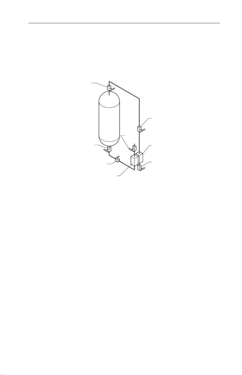
DPU Level with Tank Bottom: Cool Liquids with Pressurized Tank
1. Open the block valves and shutoff valves.
2. Crack open the DPU low-pressure drain valve and close it when liquid
stops owing from it.
3. Crack open the DPU high-pressure vent valve and close it when bubble-
free liquid ows from it.
VALVE
VENT
BLOCK
VALVE
VALVE
DPU
SHUT-OFF
VALVE
Figure A.8—Cool Non-Condensing Liquid, DPU Level with Tank Bottom
DRAIN
VALVE
A-9
Page 42
Appendix A Model 752 and 752A Differential Pressure Transmitters
HIGH-PRESSURE
SHUT-OFF
VALVE
SHUT-OFF
BLOCK
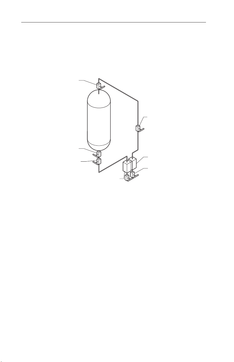
DPU Below Tank Bottom: Cool Liquids with Pressurized Tank
1. Open the block valves and shutoff valves.
2. Crack open the DPU low-pressure drain valve and close it when liquid
stops owing from it.
3. Crack open the DPU high-pressure drain valve and close it when bubble-
free liquid ows from it.
VALVE
VALVE
BLOCK
VALVE
Figure A.9—Cool Non-Condensing Liquid, DPU Below Tank
DPU
DRAIN
VALVE
A-10
Page 43

Model 752 and 752A Differential Pressure Transmitters Appendix A
Product Warranty
A. Warranty
Cameron International Corporation (“Cameron”) warrants that at the time of shipment, the
products manufactured by Cameron and sold hereunder will be free from defects in mate-
rial and workmanship, and will conform to the specications furnished by or approved by
Cameron.
B. Warranty Adjustment
1. If any defect within this warranty appears, Buyer shall notify Cameron immediately
2. Cameron agrees to repair or furnish a replacement for, but not install, any product
which within one (1) year from the date of shipment by Cameron shall, upon test and
examination by Cameron, prove defective within the above warranty.
3. No product will be accepted for return or replacement without the written authoriza-
tion of Cameron. Upon such authorization, and in accordance with instructions by
Cameron, the product will be returned shipping charges prepaid by Buyer. Replacements made under this warranty will be shipped prepaid.
C. Exclusions from Warranty
1. THE FOREGOING WARRANTY IS IN LIEU OF AND EXCLUDES ALL OTHER
EXPRESSED OR IMPLIED WARRANTIES OF MERCHANTABILITY, OR FITNESS FOR A PARTICULAR PURPOSE, OR OTHERWISE.
2. Components manufactured by any supplier other than Cameron shall bear only the
warranty made by the manufacturer of that product, and Cameron assumes no responsibility for the performance or reliability of the unit as a whole.
3. “In no event shall Cameron be liable for indirect, incidental, or consequential damages nor shall the liability of Cameron arising in connection with any products sold
hereunder (whether such liability arises from a claim based on contract, warranty, tort,
or otherwise) exceed the actual amount paid by Buyer to Cameron for the products
delivered hereunder.”
4. The warranty does not extend to any product manufactured by Cameron which has
been subjected to misuse, neglect, accident, improper installation or to use in violation
of instructions furnished by Cameron.
5. The warranty does not extend to or apply to any unit which has been repaired or
altered at any place other than at Cameron’s factory or service locations by persons
not expressly approved by Cameron.
Product Brand
Barton® is a registered trademark of Cameron International Corporation (“Cameron”).
A-11
Page 44

www.c-a-m.com/measurement
HEADQUARTERS (HOUSTON, TX)
1.281.582.9500
UNITED STATES
1.800.654-3760
CANADA
1.403.291.4814
ASIA PACIFIC
+603.7954.0145
MIDDLE EAST & NORTH AFRICA
971.4802.7700
INDIA
91.982.2431686
EUROPE, CASPIAN, RUSSIA & S. AFRICA
+44.1892.518000
LATIN AMERICA
+55.21.2172.9714
 Loading...