

Page 1

BARTON® NUCLEAR
MODELS 351/352/353
LIQUID LEVEL SYSTEMS
Installation Manual
Part No. 9A-C10521, Rev. 03
Contents
Safety ............................................................................................................... 2
Section 1— Introduction ................................................................................ 3
General ......................................................................................................... 3
Product Description....................................................................................... 4
Model 351 Liquid Level System ................................................................ 4
Model 352 Liquid Level System ................................................................ 4
Model 351/352 System Sensors ............................................................... 4
Model 353 Liquid Level System ................................................................ 5
Sensor Housings and Capillary Tubing ......................................................... 5
Specications ................................................................................................ 6
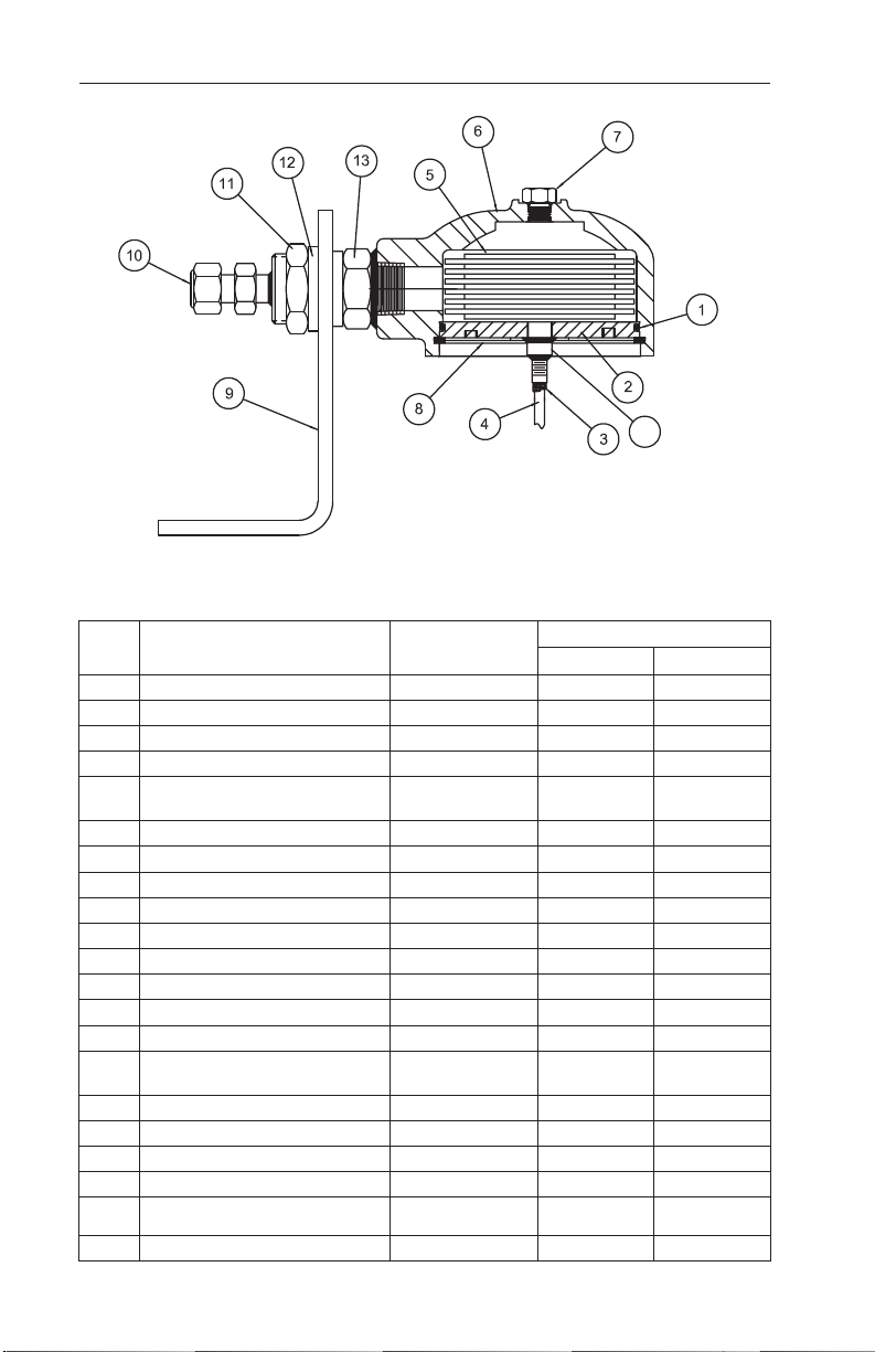
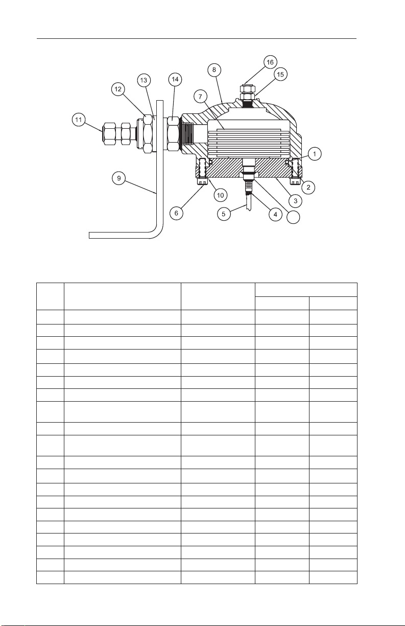
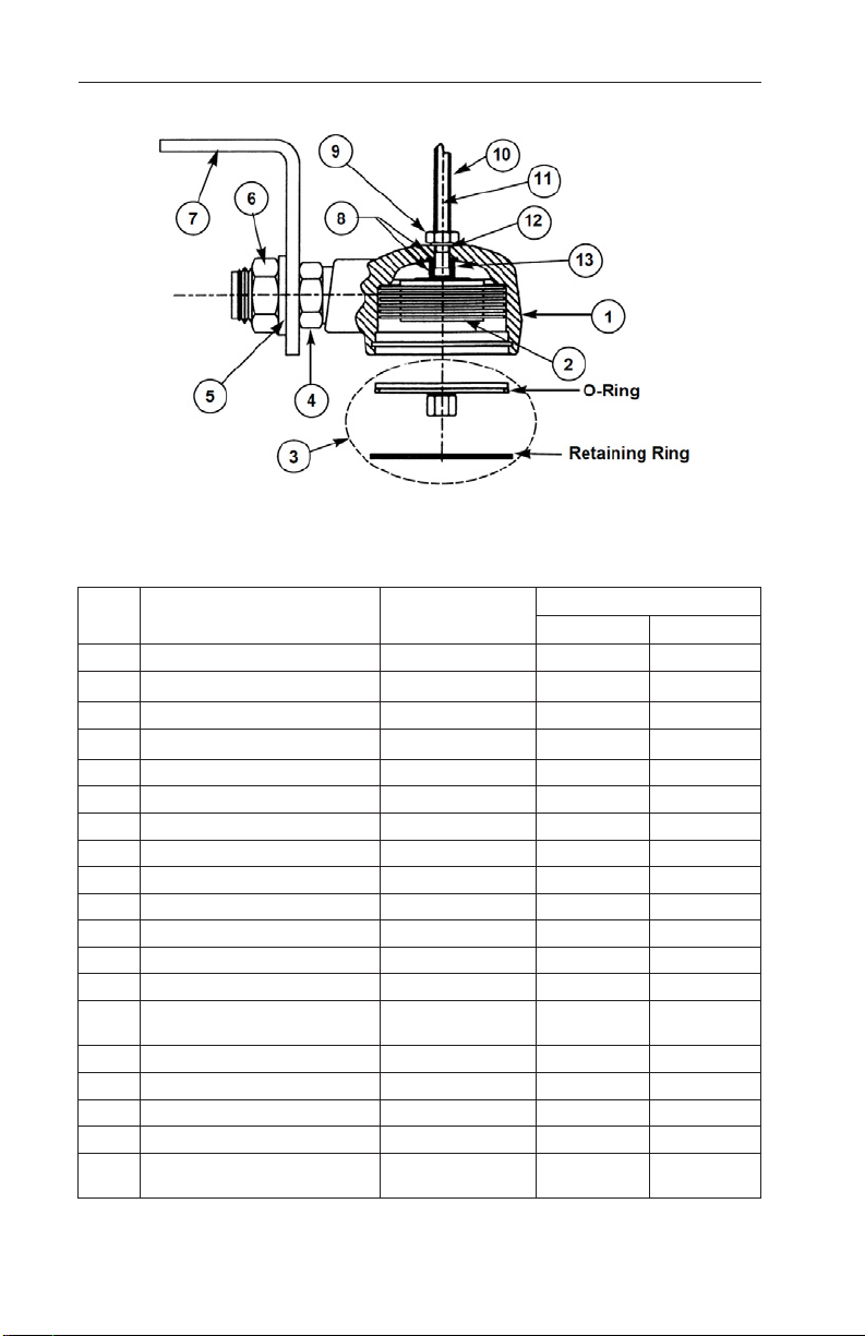
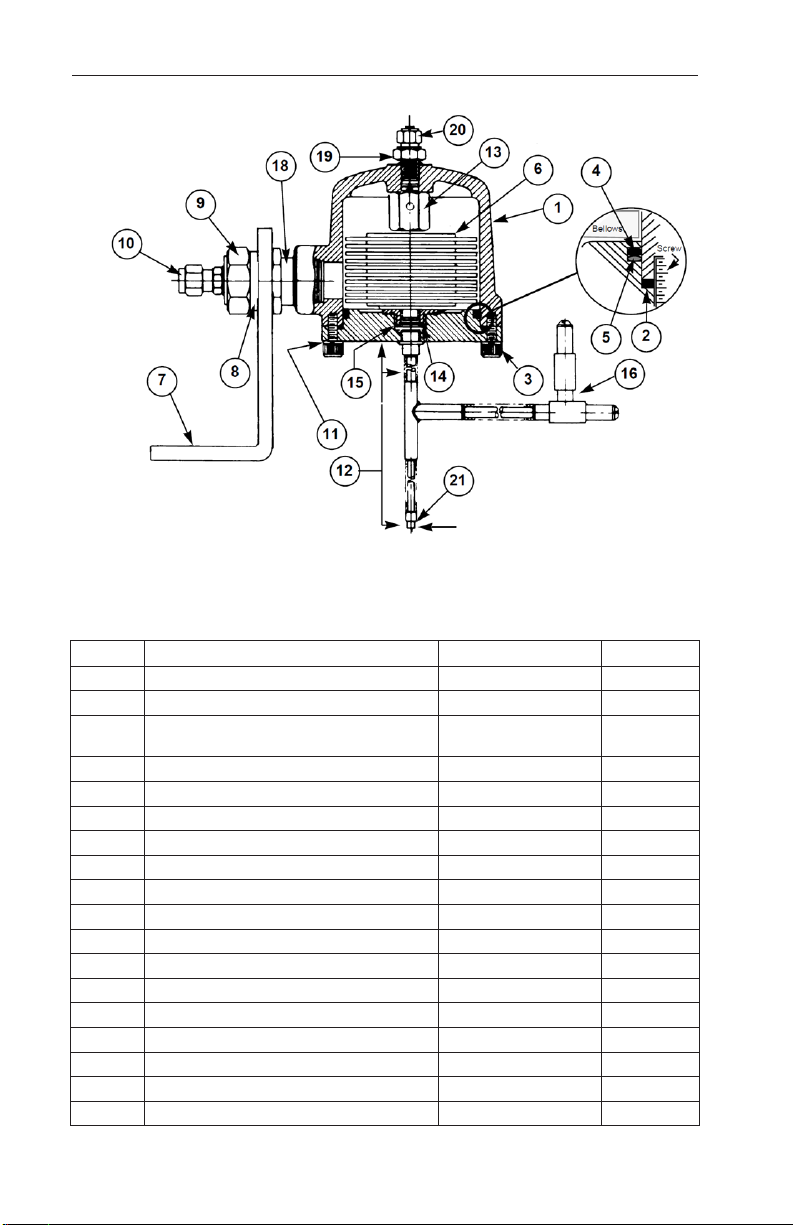
Section 2—Theory of Operation .................................................................... 7
General ......................................................................................................... 7
Model 353 Sensor ..................................................................................... 7
Section 3—Installation ................................................................................... 9
Unpacking ..................................................................................................... 9
Model 353 Sensor Assembly ..................................................................... 9
Mounting ....................................................................................................... 9
Piping and Installation ................................................................................... 9
Section 4—Operation, Maintenance, and Calibration ............................... 13
Startup ........................................................................................................ 13
General Field and Periodic Maintenance .................................................... 13
Model 351 Sensor Inspection and Cleaning............................................ 13
Model 353 Sensor Inspection and Cleaning ........................................... 13
Model 353 Sensor Bellows Removal/Replacement .................................... 14
Calibration ................................................................................................... 16
Troubleshooting .......................................................................................... 16
Section 5—Parts List.................................................................................... 17
General ....................................................................................................... 17
Section 6—Dimensional Drawings ............................................................. 27
General ....................................................................................................... 27
Product Warranty ........................................................................................ 33
Product Brand ............................................................................................. 33
November 2015
Page 2

Safety
Before installing this product, become familiar with the installation instructions presented in Section 3. In addition, adhere to the following safety
precautions:
Pressure – The instrument shall not be subjected to pressure higher than the
safe working pressure stamped on the pressure housings.
Corrosion – The bellows and O-rings of the sensors shall not be subjected to
media incompatible with ethylene propylene and 316 stainless steel.
Vibration and Shock – The instrument shall not be subjected to severe mechanical vibration or hydraulic shock.
WARNING:Thissymbolidentiesinformationaboutpracticesorcircum-
!
stances that can lead to personal injury or death, property damage, or
economic loss.
CAUTION: Indicates actions or procedures which if not performed correctly
IMPORTANT: Indicates actions or procedures which may affect instrument operation or
may lead to personal injury or incorrect function of the instrument
or connected equipment.
may lead to an instrument response that is not planned.
2
Page 3

Model 351/352/353 Liquid Level Systems Section 1
Section 1— Introduction
General
The Barton Liquid Level System provides accurate hydraulic transmission of
a process medium for measuring the level of liquids contained in a process
vessel. The self-contained system is typically mounted outside the vessel.
Floats, levers, pins, and other mechanical devices susceptible to contamination or wear are not required. Because the basic system is actuated by the
process media, local indication is possible without external power.
Barton Liquid Level Sensors can be purchased as a component of a factory-
built system, or as a part for a eld-installed system. Sealed sensor systems
can be designed in the following congurations:
• a single sensor system (Model 351)
• a dual-sensor system (Model 352)
For applications involving corrosive uids or tank temperatures above 200°F
(95°C), a dual-sensor conguration is recommended.
For applications involving unusual ll requirements due to liquid volumes or
high ambient temperatures, a Model 353 system is recommended. The Model
353 system can be designed with one or two sensors. See Model 353 Liquid
Level System on page 5 for details.
Process vessel
Single sensor
DPU
(shown
with
indicator)
Single-Sensor System
Figure 1.1—Single-sensor and dual-sensor system congurations
IMPORTANT: In this manual, the term “sensor,” refers to a mechanical bellows as-
sembly and its pressure housing used to detect and transmit a hydraulic
or pneumatic signal to an electronic transmitter, mechanical indicator or
switch.
Sensor
Sensor
Dual-Sensor System
3
Page 4

Section 1 Model 351/352/353 Liquid Level Systems
Product Description
Model 351 Liquid Level System
The Model 351 consists of a single reference sensor connected by capillary
tubing to a Barton Differential Pressure Unit (DPU). Hydraulic uid is sealed
inside the sensor and the capillary tubing, eliminating the need for additional
piping.
The Model 351 system, as shipped from the factory, needs only to be mounted on the vessel to provide continuous level measurement when used with a
Barton readout instrument. The sensor can be installed on vented or sealed
process vessels. The readout instrument (DPU, for example) can be installed
at various elevations (i.e., below the vessel, at the vessel upper connection or
above the vessel ) as long as the instrument calibration considers the elevation
difference between the instrument and the sensor.
Model 352 Liquid Level System
The Model 352 consists of two reference sensors connected by capillary tubing to a Barton DPU.
Unlike the Model 351 system, the process media does not come into contact
with the DPU, making the model ideal for applications involving corrosive
liquids or tank temperatures above 200°F (95°C).
The DPU can be mounted up to 50 ft (15 meters) away from the vented or
sealed process vessel and at ele vations up to 30 ft (9 meters) above the lowest
sensor. Elevation of the readout instrument (DPU) with respect to the sensors
is essentially unlimited as long as the instrument calibration considers the
elevation difference between the two sensors.
Model 351/352 System Sensors
A Model 351 or Model 352 system can include any of three sensor types,
depending on the pressure rating required:
• 500-psi SWP sensor (referred to as Model 351 sensor throughout this
document)
• 3,000-psi SWP sensor (referred to as Model 351 sensor throughout this
document)
• No-pressure-rating sensor (referred to as Model S048 sensor throughout
this document)
All three sensor types contain a 3.75” (95 mm) bellows that functions as a
seal. As pressure on the bellows varies due to changes in liquid level and/or
process system pressure variations, these pressure variations are transmitted
through the liquid lled sensor and capillary tubing to the readout instrument.
4
Page 5

Model 351/352/353 Liquid Level Systems Section 1
The S048 sensor is constructed with the same housing as the 500-psi SWP sensor for mounting purposes, but has no pressure rating and is designed to mount
inside open ves sels or sumps. The large bottom opening of the sensor prevents
fouling of the sensor ports due to dirt, loose debris, or other contamination.
Model 353 Liquid Level System
The Model 353 system is designed specically for unusual ll liquid requirements due to liquid volumes or high ambient temperatures.
A Model 353 system can be designed with one or two sensors. Systems are
typically assembled in the eld.
The Model 353 high-volume sealed sensor is rated for a 3,000-psi SWP and
contains a single removable bellows with an initial volume of 10 in.³ (164
cc). The bellows is 2.25 in. (57 mm) long and has a diameter of 3.75 in. (95
mm). It can extend an additional 1 in. (25 mm), adding an additional 7.5 in.³
(123 cc) to its volumetric capacity (see Figure 1.2). When the bellows is fully
compressed, an internal valve closes to prevent the escape of process uids.
The bellows may be removed for replacing a dam aged bellows or for pressure
testing the capillary tubing.
Travel to
close valve
0.84 in. (21 mm)
Normal length
2.25 in. (57 mm)
1 in. (25 mm)
Expanded bellows
Figure 1.2—Model 353 bellows travel (approximate dimensions)
Sensor Housings and Capillary Tubing
All sensors have stainless steel housings. Capillary tubing connecting the sensor to the DPU is either 1/4-in. or 3/16-in. OD. Tubing length is deter mined
by the installation. Capillary tubing may be bent or looped as required. A
1/4-in. NPT plug or a high-pressure tting (3/8-in. OD tubing) in the housing
facilitates venting.
5
Page 6

Section 1 Model 351/352/353 Liquid Level Systems
Specications
Specications for Barton sealed sensor systems are presented in Tables 1.1
and 1.2.
CAUTION: Never operate the system at pressures exceeding the safe working
pressureofthesensorangeorattachedinstrument,whicheveris
lower. Periodic testing at pressures up to 150% of the safe working
pressure is permitted, provided the pressure is applied equally and
simultaneously to the entire system.
Table1.1—SensorSpecications
Specication Model S048 Model 351 Model 353
Housing Material 316 SST 316 SST 316 SST
Safe Working Pressure N/A 500 or 3000 psi
(3.5 or 20.7 MPa)
Bellows Material
Housing Seals
Bellows Volume
Nominal 3.5 in.³
Thermal Expansion
Bellows Seals O-rings O-rings O-rings
316L SST 316L SST
N/A O-ring & Backup
(57.4 cc)
N/A N/A
O-ring
3.5 in.³
(57.4 cc)
3000 psi
(20.7 MPa)
316L SST
O-ring, Backup
O-ring, and Flat
Nickel Gasket
10 in.³
(165 cc)
17.5 in.³
(288 cc)
Table1.2—CapillarySpecications
Specication 1/4-in. OD 3/16-in. OD
Material 316 SST 304L SST
Outside Diameter ¼ in. (6.4 mm) 3/16 in. (4.8 mm)
Wall Thickness 0.060 in. (1.5 mm) 0.049 in. (1.2 mm)
Capillary Armor Material 302 SST 316 SST
Capillary Fill Material Silicone Oil, Water, Ethylene
Glycol & Water or Mineral Oil
Weight (with armor) 0.25 lb/ft (350 g/m) 0.25 lb/ft (350 g/m)
Bend Radius (minimum) 2 in. (50 mm) 2 in. (50 mm)
Silicone Oil, Water, Ethylene
Glycol & Water or Mineral Oil
6
Page 7

Model 351/352/353 Liquid Level Systems Section 2
Section 2—Theory of Operation
General
A uid column exerts a pressure proportional to its height and density, independent of the shape or volume of the containing vessel. A differential pres-
sure unit (DPU) can be calibrated to indicate the height of a uid when the
uid density is known. In tanks of given dimensions, the weight and volume
of contents can be measured by a DPU.
One or two sealed sensors are connected to the DPU by capillary tubing.
These sensors contain bellows which function as “isolation seals.” As pressure on the sensor bellows varies due to changes in liquid level, the variations
are transmitted hydraulically through the tubing to the bellows of the DPU.
Model 351/Model S048 Sensors
The pressure deection characteristics of the Model 351 (500-psi or 3,000psi) and Model S048 sensor bellows are shown in Figure 2.1.
Figure 2.1—Pressure deection characteristics of the Model 351/352 sensor bellows
Model 353 Sensor
In the event of thermal expansion of the ll-liquid in the capillary tubing
and in the other instruments, the Model 353 sensor bellows can extend 1 in.
(25 mm) for 7.5 in.³ (123 cc) displacement. If leakage occurs in the capillary
tubing, the bel lows becomes compressed approximately 0.56 in. (14 mm) and
7
Page 8

Section 2 Model 351/352/353 Liquid Level Systems
then closes an internal valve to prevent further loss of bel lows liquid. This
action prevents escape of process liquid.
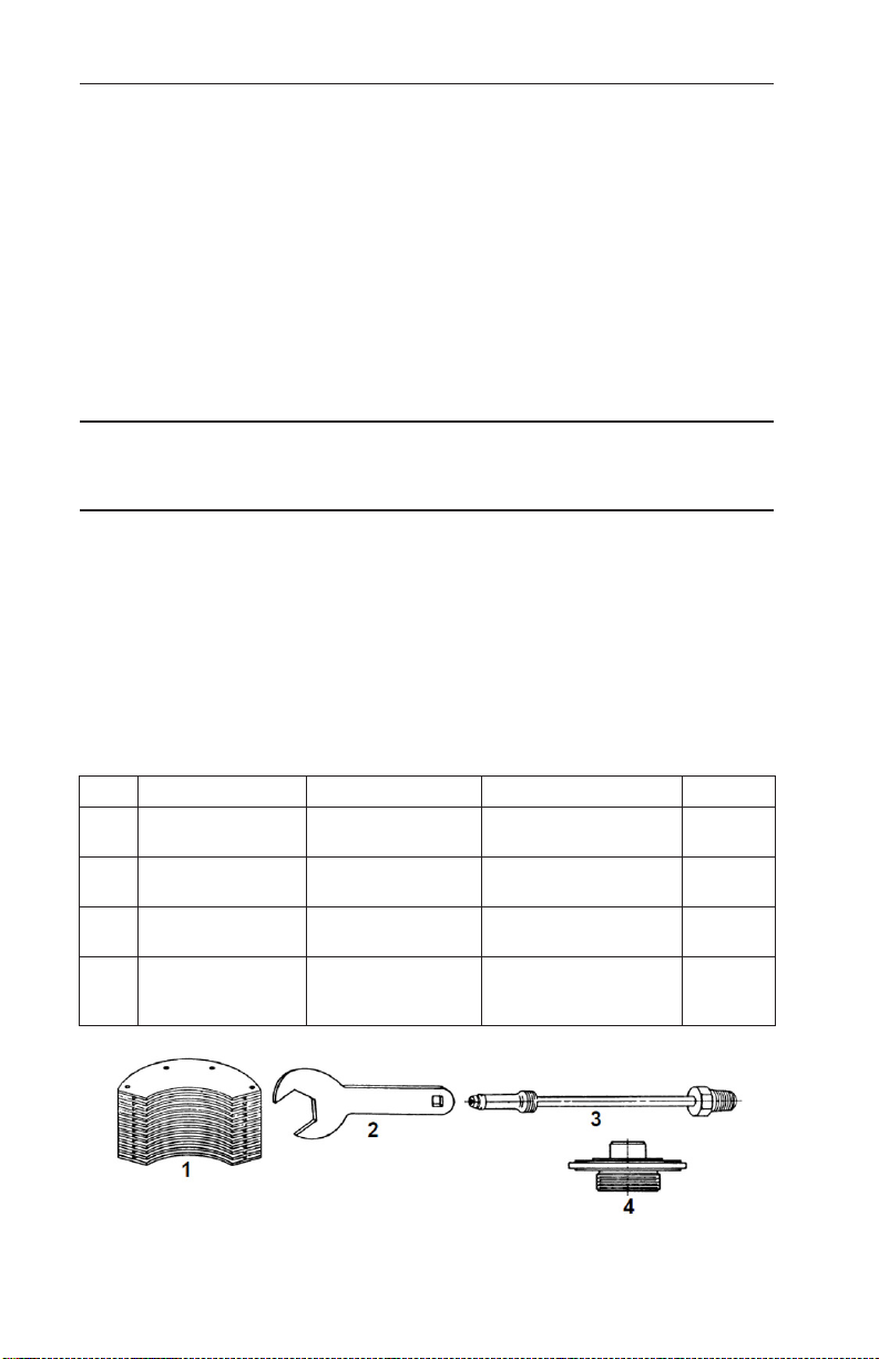
The sensor bellows may be removed with a special wrench (see Table 4.1 and
Figure 4.1, page 14). This permits pressure testing and leak testing of the hous-
ing and capillary tubing and allows damaged parts to be replaced before the
system is lled.
The pressure deection characteristics of the Model 353 sensor bellows are
shown in Figure 2.2.
1 in. (25 mm)
Normal length
2.25 in. (57 mm)
Travel to
fully close valve
0.84 in. (21 mm)
Figure 2.2—Pressure deection characteristics of the Model 353 sensor bellows
The bellows can extend over 1 in. (25 mm) to accommodate ll uid expansion under hot operating conditions. As seen in Figure 2.2, the expansion
creates an internal pressure of 25.7 in. H2O (6.4 kPa) at 1 in. (25 mm). When
compressed, the bellows travels approximately 0.5 in. (13 mm) before the
internal valve begins to close. Compression of the bellows to 0.5 in. (13 mm)
requires approximately 10 in. H2O (2.6 kPa) of external pressure.
8
Page 9

Model 351/352/353 Liquid Level Systems Section 3
Section 3—Installation
Unpacking
All instruments are inspected during manufacture and prior to shipping. However, an inspection should be performed at the time of unpacking to detect
any damage that may have occurred during shipping.
When unpacking, carefully remove the instrument from the container. If the
instrument is a liquid-lled sys tem, remove the strap-fasteners and gently
unroll the capillary tubing.
The transmitter output may indicate “Near Full Scale” if the system is tested
prior to installation. This is nor mal, and the transmitter output will be correct
when the reference leg is elevated.
Model 353 Sensor Assembly
The Model 353 sensor bellows and bottom plate bolts are not torqued to
installation requirements as shipped. See Section 4 on page 13 for instructions on removal and replacement of Model 353 sensor bellows.
Mounting
Mount the sensors as close to vertical orientation as possible to ensure proper
operation. The sensor may be oriented with the vent pointed up or down,
depending on the service or installation design.
When mounted with the L-bracket, mount the sensors with three 3/8-16 SAE
bolts, Grade 5 or better, torqued to 24 to 26 ft-lb (33-35 N-m). The mounting bracket may be rotated axially or reversed, as required for installation (as
shown in dimensional drawings in Section 6).
Interfacing process tubing should be supported to minimize relative motion
between the sensor and connections. The capillary tubing should be supported
with at least one support located within 1 ft (0.3 meters) of the sensor. The
minimum bend radius of the capillary tubing is 2 in. (50 mm).
Piping and Installation
IMPORTANT: Sealed systems are normally lled at the factory, but can be installed and
lled in the eld.
Sensors should be connected in accordance with user specications. Flanges
and tube ttings (3/8”, 1/2” or 3/4”) are available for this purpose.
9
Page 10

Section 3 Model 351/352/353 Liquid Level Systems
Capillary Tubing Welding
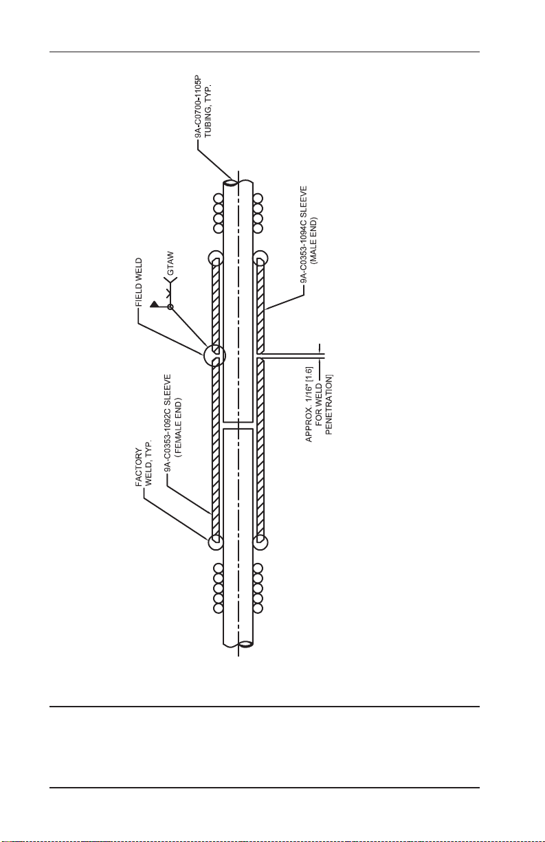
Figures 3.1 through 3.3 present the information and procedures necessary to
weld the capillary tubing and tubing coupling.
Figure 3.1—1/4-in. OD capillary tubing welds
IMPORTANT: All parts are solution annealed 316 or 304 stainless steel. Please adhere
10
to the following welding practices:
(1) Weld type: GTAW llet, 45 amps, 10 volts, 20 CFH (9.5 l/m) Argon
gas ow.
(2) Use 1/16” dia. Type 308 ller rod
Page 11

Model 351/352/353 Liquid Level Systems Section 3
Figure 3.2—3/16-in. OD capillary tubing welds
IMPORTANT: All parts are solution annealed 304L stainless steel. Please adhere to the
following welding practices:
(1) Weld type: GTAW llet, 45 amps, 10 volts, 20 CFH (9.5 l/m) Argon
gas ow.
(2) Use 1/16” dia. Type 308 ller rod
11
Page 12
Section 3 Model 351/352/353 Liquid Level Systems
NOTE—Weldment should join both ends (male/female) using the capillary tubing as a “backup ring.”
Penetration through the tubing wall is not required.
Figure 3.3—3/16-in. OD capillary tubing coupling welds
IMPORTANT: All parts are solution annealed 304L stainless steel. Please adhere to the
12
following welding practices:
(1) Weld type: GTAW V-groove, 45 amps, 10 volts, 20 CFH (9.5 l/m)
Argon gas ow.
(2) Use 1/16” dia. Type 308 ller rod
Page 13

Model 351/352/353 Liquid Level Systems Section 3
Section 4—Operation, Maintenance, and Calibration
Startup
Startup and operating instructions for an instrument actuated by the Liquid
Level System are presented in the installation and operation manual for that
instrument.
General Field and Periodic Maintenance
The sensor is basically maintenance-free. If installed in an application where
sediment can accumulate in the bel lows convolutions, periodic inspection and
cleaning may be required.
CAUTION: The sensor bellows can be damaged by contact with the housing.
Model 351 Sensor Inspection and Cleaning
When removing the sensor assembly, avoid unnecessary contact
with the housing.
1. Remove the sensor from the housing. The 500 psi (3.5 MPa) sensor is
connected by a retainer ring; the 3000 psi (20.7 MPa) sensor is connected
by 6 bolts. Carefully separate the sensor from the housing assembly.
2. Remove any accumulated material from between the bellows convolutions, using a soft brush and solvent as required.
3. Inspect the O-rings and seals before reassembly. Replace as necessary
(see note on page 17).
4. Replace the housing over the sensor bellows. For 3000 psi (20.7 MPa)
sensors, lubricate the bolt threads and seat the bolts at 34 to 35 ft-lb (46
to 48 N-m). For 500 psi (3.5 MPa) sensors, install the retaining ring.
Model 353 Sensor Inspection and Cleaning
1. Remove the 12 bolts connecting the sensor to the housing, and carefully
separate the sensor from the housing assembly.
2. Remove any accumulated material from between the bellows convolutions, using a soft brush and solvent as required.
3. Inspect the bellows for damage. Free-length should be 2-1/4 in. (57 mm)
(see Figure 1.2). Length may vary by 1/8 in. (3 mm) due to system temperature-effects. Press lightly (by hand) on the free end of the bellows;
the bellows should be “incom pressible” if the system is liquid lled.
4. Inspect the O-ring, backup ring, and nickel gasket before reassembly.
Replace as necessary (see note on page 17).
5. Carefully replace the sensor in the housing assembly. Lubricate the bolts
lightly and torque uniformly to approximately 34 to 35 ft-lb (46 to 48
N-m).
13
Page 14
Section 3 Model 351/352/353 Liquid Level Systems
Model 353 Sensor Bellows Removal/Replacement
The sensor bellows must be removed under the following circumstances:
• when the capillary system is to be pressurized
• for argon ow during weld ing
• for static pressure tests of the capillary system
• for replacement of a damaged sensor
To remove the sensor bellows, perform the following steps:
1. Remove the 12 housing bolts. Carefully remove the bellows bottom plate
assembly from the housing.
CAUTION: The sensor bellows can be damaged by contact with the housing.
When removing the sensor assembly, avoid unnecessary contact
with the housing.
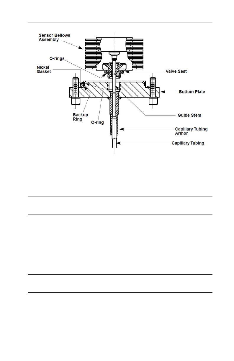
2. Remove the bellows from the bottom plate by turning the valve seat with
the sensor bellows wrench and lift ing the bellows until the guide stem is
withdrawn from the capillary tubing. Observe the two O-rings on the bottom of the valve seat; they may fall free when the bellows is lifted.
3. (Pressure Tests Only) Install a test tting with an O-ring (refer to Figure
4.1, item 4, and Figure 4.2, page 15). Tighten with the sensor bellows
wrench to 39 to 40 ft-lb (53 to 55 N-m). Remove the test tting when
pressure tests are complete.
Table 4.1—Model 353 Tools and Test Fittings
Item Description Part No. Purpose Qty
1 Sensor Bellows
Spacer Assembly
2 Sensor Bellows
Wrench
3 Fill Valve Test Fitting 9A-0353-1109B Connection for applying
4 Seal Plug Adapter 9A-S039-0087Z Replace sensor bellows
9A-0353-1069B Hold bellows in “open”
position during ll
9A-0353-1053C Removal/installation of
sensor bellows
pressure thru ll valve
assembly during
pressure tests
2 per
sensor
2
3
1 per
sensor
14
Figure 4.1—Model 353 tools and test ttings identication
Page 15
Model 351/352/353 Liquid Level Systems Section 4
Figure 4.2—Model 353 sensor bellows and bottom plate assembly
To install the sensor bellows, perform the following steps:
4. Inspect the sensor bellows to verify that the bellows is undamaged and
the guide stem is in place.
IMPORTANT: This inspection should be performed whether the old bellows or a
replacement bellows is to be installed.
5. Inspect the two O-rings in the valve seat, the O-ring and the backup ring
in the bottom plate, and the nickel gasket to verify there is no damage (see note on page 17). Install the nickel gasket on the bottom plate.
Lubricate the O-rings and backup ring lightly with lubricant (part number
9A-C0002-1003U) and insert in the appropriate grooves.
6. Engage the valve seat to the bottom plate. The guide stem must enter the
capillary tubing without restric tion.
IMPORTANT: To prevent loss of the O-rings in the valve seat, invert the bellows and
bottom plate during this step.
7. Tighten the valve seat with the sensor bellows wrench to approximately
39 to 40 ft-lb (53 to 55 N-m). Verify that a metal-to-metal t is obtained
between the valve seat and the bottom plate (zero clearance).
8. After the sensor bellows and capillary tubing are lled with liquid, carefully insert the plate and bellows assembly into the housing. Uniformly
tighten the 12 housing bolts to 34 to 35 ft-lb (46 to 48 N-m).
15
Page 16

Section 4 Model 351/352/353 Liquid Level Systems
CAUTION: The sensor bellows can be damaged by contact with the housing.
When installing the sensor assembly, avoid unnecessary contact
with the housing.
Calibration
The actuated instrument is calibrated according to the procedure presented in
the installation and operation manual for that instrument.
IMPORTANT: During calibration, the sensor should be elevated to the exact position it
will occupy in the installa tion. Otherwise, calibration pressures must be
modied to compensate for the differences in hydro static pressures.
Troubleshooting
Troubleshooting procedures for the actuated instrument are presented in the
technical manual for that instru ment.
Troubleshooting procedures for the sensor are presented in Table 4.2.
Table 4.2—Sensor Troubleshooting Chart
Problem Probable Cause Corrective Action
Transmitter reading off zero
(±1%) with empty tank.
Transmitter reading off zero
(exceeds ±1%).
Transmitter remains at fullscale.
Transmitter does not respond
to level changes.
Transmitter is slow or erratic. Sensors contaminated.
Transmitter drifts. Leak in sealed system. Repair.
Minor elevation errors. Re-zero transmitter according
Elevations of sensors (or
transmitter) are incorrect.
Sensors are reversed. Reinstall sensors, HP sensor
Sensors contaminated.
Capillary tubing closed.
Transmitter inoperative.
Capillary tubing closed.
to actuated instrument
technical manual.
Raise/lower upper sensor.
Raise/lower transmitter (single
sensor system).
to top of tank.
Clean sensors carefully.
Replace tube.
Replace parts, see actuated
instrument technical manual.
Clean sensors carefully.
Open or replace.
16
Page 17
Model 351/352/353 Liquid Level Systems Section 4
Section 5—Parts List
General
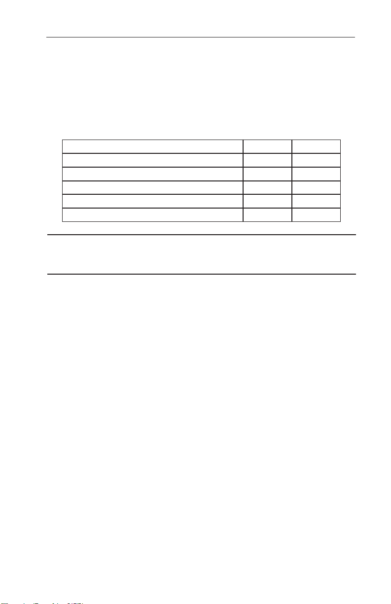
The component parts of the actuated instrument are listed and identied in
the technical manual for that instru ment. Component parts are called out in
gures and listed by sensor type in the corresponding tables.
Sensor Type Table Reference
Model 351 Sensor, 500 psi (3.5 MPa) 5.1 page 18
Model 351 Sensor, 3000 psi (20.7 MPa) 5.2 page 20
Model S048 Sensor 5.3 page 22
Model 353 Sensor 5.4 page 24
Fill -Valve Assembly 5.5 page 26
IMPORTANT: O-rings should be examined anytime the seal is opened. They should be
replaced whenever:surfaces are damaged or deteriorated, “squeeze” is
less than 0.010 in. (0.25 mm), or sealing areas have at surfaces.
17
Page 18
Section 4 Model 351/352/353 Liquid Level Systems
18
NOTE: Mounting bracket No. 9 may be reversed
or rotated to obtain the desired configuration.
Table 5.1—Model 351 Sensor Assembly
500 psi (3.5 MPa)
Item Description Part No. Qty per System**
351 352
1* O-ring 1 2
EPT 9A-C0001-1074R
Viton 9A-C0001-0131R
2 Plate, Bottom, SST 9A-C0351-0012C 1 2
3 Protective Spring, for 1/4” O.D.
Tubing, SST
4 Tubing, 1/4” O.D. Capillary, SST 9A-C0700-1014P As Required As Required
5 Bellows Assembly 1 2
SST 9A-C0351-0001B
Inconel 9A-C0351-1031B
6 Sensor Housing 1 2
1” NPT 9A-C0351-0014C
3/4” NPT 9A-CS696-0231Z
7 Vent Fitting 1 2
1/4 NPT Plug 9A-C0199-0214C
1/4 NPT Plug (drilled for Lockwire)
3/8” Tube Fitting 9A-C0505-1029M
3/8” Tube Fitting Plug 9A-C0600-1012L
8* Retainer Ring, SST 9A-C0087-1007T 1 2
9 Bracket, Mounting 9A-CS778-0078Z 1 2
10 Process Connection Tube Fitting 1 2
9A-C0305-1001C As Required As Required
9A-C0224-0272C
18
3/8” Tube 9A-C0505-1028M
Page 19

Model 351/352/353 Liquid Level Systems Section 5
Table 5.1—Model 351 Sensor Assembly
500 psi (3.5 MPa)
Item Description Part No. Qty per System**
351 352
1/2” Tube 9A-C0505-1070M
3/4” Tube 9A-C0505-1026M
11 Nut, SST 9A-C0353-1005C 1 2
12 Washer, SST 9A-C0353-1006C 1 2
13 Process Connection Adapter 1 2
3/8” Tube 9A-C0353-1010C
1/2” Tube 9A-C0353-1009C
3/4” Tube 9A-C0353-1008C
14* Lubricant, O-ring (not shown) 9A-C0002-1003U As Required As Required
15 Coupling, 1/4” O.D. Tubing (not
shown)
16 Nipples – Alternate Process
Connection to be used with a
ange (not shown)
1” Sched 40, 2” long, 316 SST 9A-CS696-0365C
1” Sched 40, 4” long, 316 SST 9A-CS696-0366C
1” Sched 40, 6” long, 316 SST 9A-CS696-0367C
1” Sched 40, 8” long, 316 SST 9A-CS696-0368C
1” Sched 80, 2” long, 316 SST 9A-CS696-0374Z
1” Sched 80, 4” long, 316 SST 9A-CS696-0373Z
1” Sched 80, 6” long, 316 SST 9A-CS696-0070Z
1” Sched 80, 8” long, 316 SST 9A-CS696-0351Z
¾” Sched 40, 8” long, 316 SST 9A-CS696-0371C
17 Flanges – Alternate Process Con-
nection to be used with a nipple
(not shown)
1” Class 150, RF/SO, 316 SST 9A-C0059-1633T
1” Class 300, RF/SO, 316 SST 9A-C0059-1632T
1” Class 600, RF/SO, 316 SST 9A-C0059-1657T
1” Class 1500, RF/SO, 316 SST 9A-C0059-1693T
2:1 Class 150, RF/SO, 316 SST 9A-CS696-0137Z
2:1 Class 600, RF/SO, 316 SST 9A-CS696-0133Z
2:1 Class 1500, RF/SO, 316 SST 9A-CS696-0115Z
3/4” Class 150, RF/SO, 316 SST 9A-C0059-1632T
3/4” Class 600, RF/SO, 316 SST 9A-C0059-1656T
3/4” Class 1500, RF/SO, 316 SST 9A-C0059-1692T
1” Class 150, FF/SO, 316 SST 9A-CS696-0375C
2:1 Class 150, FF/SO, 316 SST 9A-CS696-0363T
18 Nut, Lock, SST 9A-C0353-1013C 1 2
*Recommended Spare Parts (EPT = Ethylene Propylene Terpolymer)
** Model 351 systems have a single sensor; Model 352 systems require two sensors.
9A-C0353-1022C As Required As Required
1 2
1 2
19
Page 20
Section 5 Model 351/352/353 Liquid Level Systems
21
NOTE: Mounting bracket No. 9 may be reversed
or rotated to obtain the desired configuration.
Table 5.2—Model 351 Sensor Assembly
3000 psi (20.7 MPa)
Item Description Part No. Qty/System**
351 352
1* O-ring 1 2
EPT 9A-C0001-1074R
Viton 9A-C0001-0131R
2* Ring, Backup 1 2
EPT 9A-C0001-1116R
Viton 9A-C0001-1046R
3 Plate, Bottom, SST 9A-C0351-0018C 1 2
4 Protective Spring, for 1/4” O.D.
Tubing, SST
5 Tubing, 1/4” O.D. Capillary, SST 9A-C0700-1014P As Required As Required
6 Screw, Socket Head Cap, 3/8”-24
x 1-1/8” long, SST
7 Bellows Assembly 1 2
SST 9A-C0351-0001B
Inconel 9A-C0351-1031B
8 Sensor Housing, 1” NPT 9A-C0351-0016C 1 2
9 Bracket, Mounting 9A-CS778-0078Z 1 2
10 Washer, Split-lock, SST 9A-C0003-1171K 6 12
11 Process Connection Tube Fitting 1 2
3/8” Tube 9A-C0505-1028M
1/2” Tube 9A-C0505-1070M
3/4” Tube 9A-C0505-1026M
9A-C0305-1001C As Required As Required
9A-C0220-1039J 6 12
20
Page 21

Model 351/352/353 Liquid Level Systems Section 5
Table 5.2—Model 351 Sensor Assembly
3000 psi (20.7 MPa)
Item Description Part No. Qty/System**
351 352
12 Nut, SST 9A-C0353-1005C 1 2
13 Washer, SST 9A-C0353-1006C 1 2
14 Process Connection Adapter 1 2
3/8” Tube 9A-C0353-1010C
1/2” Tube 9A-C0353-1009C
3/4” Tube 9A-C0353-1008C
15 Vent Fitting 1 2
1/4 NPT Plug 9A-C0199-0214C
1/4 NPT Plug (drilled for Lockwire) 9A-C0224-0272C
3/8” Tube Fitting 9A-C0505-1029M
16 Vent Fitting Plug – 3/8 Tube
Fitting Plug
17* Lubricant, O-ring (not shown) 9A-C0002-1003U As Required As Required
18 Coupling, 1/4” O.D. Tubing (not
shown)
19 Nipples – Alternate Process Con-
nection to be used with a ange
(not shown)
1” Sched 40, 2” long, 316 SST 9A-CS696-0365C
1” Sched 40, 4” long, 316 SST 9A-CS696-0366C
1” Sched 40, 6” long, 316 SST 9A-CS696-0367C
1” Sched 40, 8” long, 316 SST 9A-CS696-0368C
1” Sched 80, 2” long, 316 SST 9A-CS696-0374Z
1” Sched 80, 4” long, 316 SST 9A-CS696-0373Z
1” Sched 80, 6” long, 316 SST 9A-CS696-0070Z
1” Sched 80, 8” long, 316 SST 9A-CS696-0351Z
20 Flanges – Alternate Process Con-
nection to be used with a nipple
(not shown)
1” Class 150, RF/SO, 316 SST 9A-C0059-1633T
1” Class 300, RF/SO, 316 SST 9A-C0059-1632T
1” Class 600, RF/SO, 316 SST 9A-C0059-1657T
1” Class 1500, RF/SO, 316 SST 9A-C0059-1693T
2:1 Class 150, RF/SO, 316 SST 9A-CS696-0137Z
2:1 Class 600, RF/SO, 316 SST 9A-CS696-0133Z
2:1 Class 1500, RF/SO, 316 SST 9A-CS696-0115Z
21 Nut, Lock, SST 9A-C0353-1013C 1 2
*Recommended Spare Parts (EPT = Ethylene Propylene Terpolymer)
** Model 351 systems have a single sensor; Model 352 systems require two sensors.
9A-C0600-1012L 1 2
9A-C0353-1022C As Required As Required
1 2
1 2
21
Page 22
Section 5 Model 351/352/353 Liquid Level Systems
NOTE: Mounting bracket No. 7 may be reversed
or rotated to obtain the desired configuration.
Table 5.3—Model S048 Sensor Assembly
Item Description Part No. Qty/System**
351 352
1 Sensor Housing, SST 1 2
1” NPT (L-bracket mounting) 9A-CS048-0007Z
1” S/O (ange mounting) 9A-CS048-0002Z
2 Sensor Bellows Assembly 1 2
SST 9A-C0351-0001B
Inconel 9A-C0351-1031B
3* Test Assembly 9A-CS048-0018B 1 2
4 Sensor Adapter, SST 9A-C0353-1010C 1 2
5 Washer, SST 9A-C0353-1006C 1 2
6 Nut, SST 9A-C0353-1005C 1 2
7 Bracket, Mounting 9A-CS778-0078Z 1 2
8 O-ring, 014, EPT 9A-C0001-1050R 2 4
9 Nut, SST 9A-CS048-0041C 1 2
10 Protective Spring, for 1/4” O.D.
Tubing, SST
11 Tubing, Capillary, 1/4” O.D., SST 9A-C0700-1014P As Required As Required
12 Washer, SST 9A-C0003-0089K 1 2
13 Spacer, SST 9A-CS048-0004Z 1 2
14* Lubricant, O-ring (not shown) 9A-C0002-1003U As Required As Required
15 Coupling, 1/4” O.D. Tubing (not
shown)
9A-C0305-1001C As Required As Required
9A-C0353-1022C As Required As Required
22
Page 23

Model 351/352/353 Liquid Level Systems Section 5
Table 5.3—Model S048 Sensor Assembly
Item Description Part No. Qty/System**
351 352
16 Nipples – Alternate mounting
to be used with a ange (not
shown)
1” Solid, 2” long, 316 SST 9A-CS696-0065Z
1” Solid, 6” long, 316 SST 9A-CS696-0151Z
17 Flanges – Alternate mounting
to be used with a nipple (not
shown)
1” Class 150, FF/SO, 316 SST 9A-CS696-0375C
2:1 Class 150, FF/SO, 316 SST 9A-CS696-0363T
* Recommended Spare Parts (EPT = Ethylene Propylene Terpolymer)
** Model 351 systems have a single sensor; Model 352 systems require two sensors.
1 2
1 2
23
Page 24
Section 5 Model 351/352/353 Liquid Level Systems
0.192/0.197 in. (4.9/5.0 mm) ID
NOTE: Mounting bracket No. 7 may be reversed
or rotated to obtain the desired configuration.
Table 5.4—Model 353 Sensor Assembly
Item Description Part No. Qty
1 Sensor Housing, SST 9A-C0353-1133B 1
2* Gasket, Housing, Nickel 9A-C0353-1058C 1
3 Screw, Socket Head Cap, 3/8”-24 x 1-1/2”
long, SST
4* O-ring, EPT 9A-C0001-1074R 1
5* Ring, Backup, EPT 9A-C0001-1116R 1
6 Bellows Assembly, SST 9A-C0353-1036B 1
7 Bracket 9A-CS778-0078Z 1
8 Washer, SST 9A-C0353-1006C 1
9 Nut, SST 9A-C0353-1005C 1
10 Process Connection Tube Fitting 1
3/8” Tube 9A-C0505-1028M
1/2” Tube 9A-C0505-1070M
3/4” Tube 9A-C0505-1026M
11 Washer, Split Lock, 3/8”, SST 9A-C0003-1171K 12
12 Plate and Pigtail Assembly 9A-C0353-1050B 1
13 Plug, SST 9A-C0353-1060C 1
14* O-ring, EPT 9A-C0001-1052R 1
15* O-ring, EPT 9A-C0001-1053R 1
9A-C0220-1028J 12
24
Page 25

Model 351/352/353 Liquid Level Systems Section 5
Table 5.4—Model 353 Sensor Assembly
Item Description Part No. Qty
16 Fill Valve & Tee Assembly (See Figure 5-5) 9A-C0351-1044B 1
17* Lubricant, O-ring (not shown) 9A-C0002-1003U As Required
18 Process Connection Adapter 1
3/8” Tube 9A-C0353-1010C
1/2” Tube 9A-C0353-1009C
3/4” Tube 9A-C0353-1008C
19 Adapter, 1/4” NPT x 3/8” Tube, SST 9A-C0505-1029M 1
20 Plug, 3/8” Tube, SST 9A-C0600-1012L 1
21 Adapter, Capillary Tubing, 1/4” O.D. x 3/16”
O.D., SST
22 Capillary, Armored, 3/16” O.D., 0.049” Wall,
200 ft (61 m) in length
23 Sleeve, Female 3/16” O.D. Tubing Coupling
(not shown)
24 Sleeve, Male, 3/16” O.D. Tubing Coupling
(not shown)
25 1” Sched. 160, 316L SST, 9” long alternate
process connection (not shown)
*Recommended Spare Parts (EPT = Ethylene Propylene Terpolymer)
9A-C0353-1080C 1
9A-C0353-1090B As Required
9A-C0353-1092C As Required
9A-C0353-1094C As Required
9A-C0353-1059C 1
25
Page 26
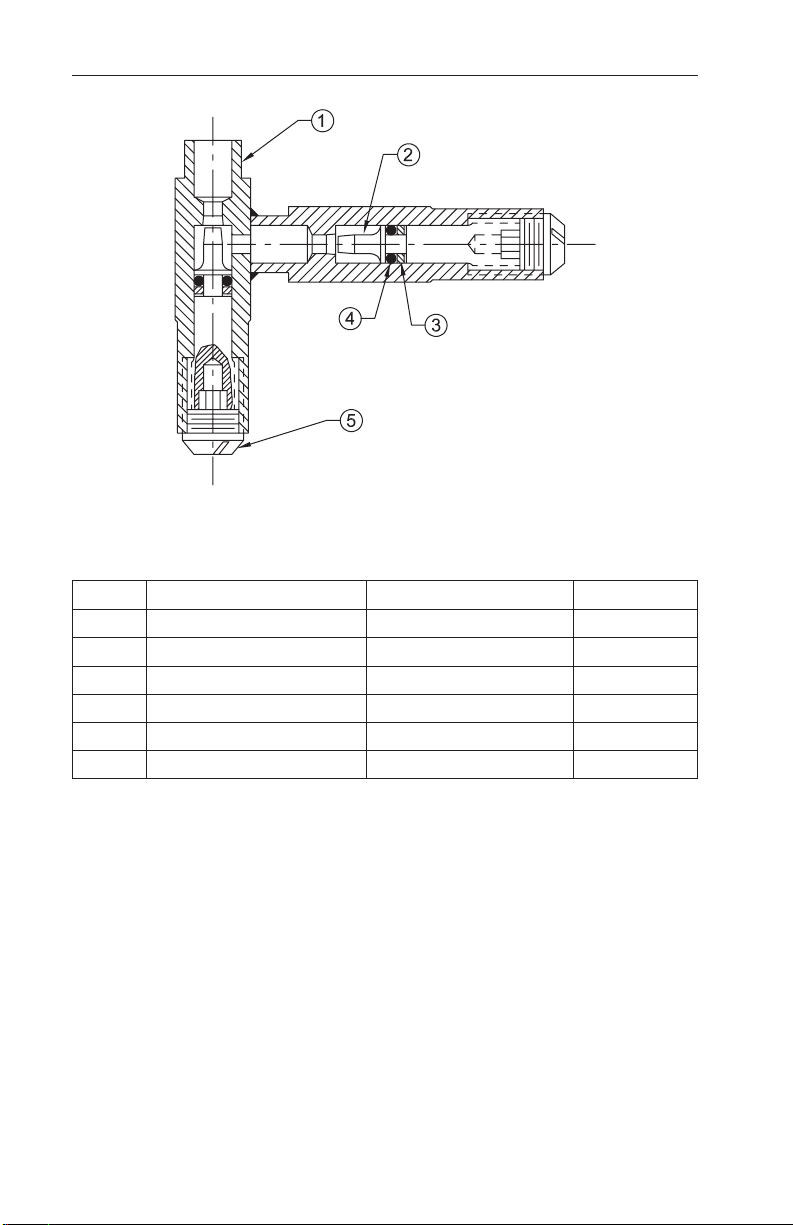
Section 5 Model 351/352/353 Liquid Level Systems
(Part of Fill Valve & Tee Assembly, Part No. 9A-C0351-1044B)
Table 5.5—Fill Valve Assembly
Item Description Part No. Qty/Unit
1 Valve Body Assembly 9A-C0353-1014B 1
2 Valve 9A-C0353-1011C 2
3* O-ring, Backup, EPT, #8-006 9A-C0001-1062R 2
4* O-ring, EPT, #2-006 9A-C0001-1063R 2
5* Fill Valve Cover 9A-C0353-1012C 2
6* Lubricant, O-ring (not shown) 9A-C0002-1003U As Required
*Recommended Spare Parts (EPT = Ethylene Propylene Terpolymer)
26
Page 27

Model 351/352/353 Liquid Level Systems Section 5
Section 6—Dimensional Drawings
General
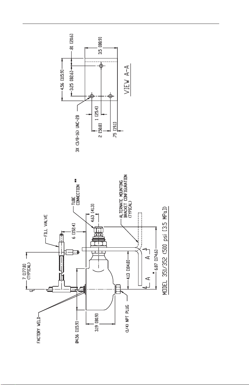
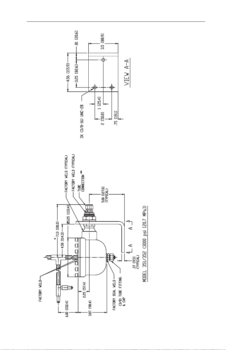
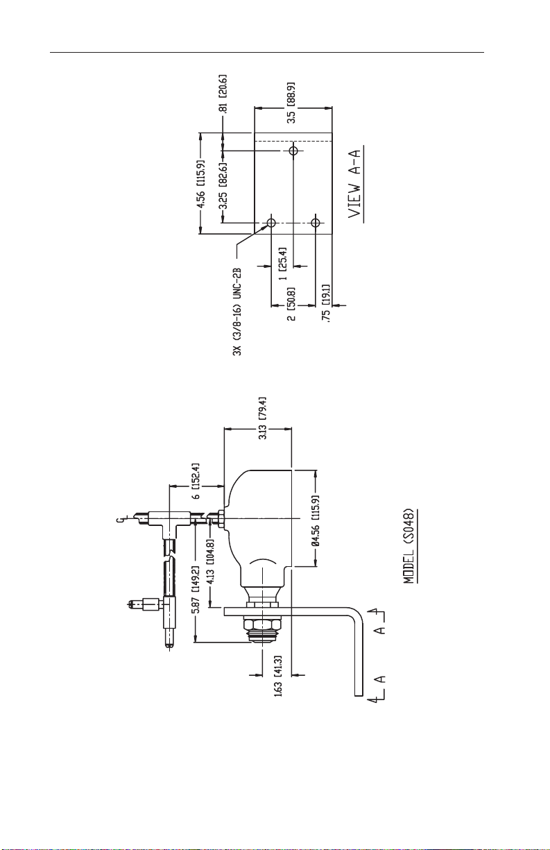
The drawings in this section show the outline dimensions for each sensor as-
sembly. These images are based on production drawing 9A-C0351-10782.
Liquid Level System Type Figure Reference
Model 351, 500 psi (3.5 MPa) 6.1 page 28
Model 351, 3000 psi (20.7 MPa) 6.2 page 29
Model S048 6.3 page 30
Model 353, 3000 psi (20.7 MPa) 6.4 page 31
27
Page 28
Section 5 Model 351/352/353 Liquid Level Systems
*DIMENSION VARIES WITH TUBE FITTING SIZE.
** AVAILABLE IN 3/8, 1/2, & 3/4 IN. TUBE SIZES. ALSO AVAILABLE WITH 3/4" & 1" PIPE WITH FLANGE CONNECTION.
4. MOUNTING BRACKET CAN BE ROTATED OR REVERSED AS NECESSARY TO SATISFY INSTALLATION REQUIREMENTS.
3. TORQUE BOTTOM PLATE CAP SCREWS TO 35 FT-LB [47 N-m].
2. TORQUE MOUNTING BRACKET NUT TO 147.5 FT-LB [200 N-m].
1. ALL DIMENSIONS ARE ± 0.13 IN. [3.2 MM] UNLESS OTHERWISE NOTED.
28
Figure 6.1—Model 351 sensor, 500 psi (3.5 Mpa)
Page 29
Model 351/352/353 Liquid Level Systems Section 6
*DIMENSION VARIES WITH TUBE FITTING SIZE.
** AVAILABLE IN 3/8, 1/2, & 3/4 IN. TUBE SIZES. ALSO AVAILABLE WITH 3/4" & 1" PIPE WITH FLANGE CONNECTION.
4. MOUNTING BRACKET CAN BE ROTATED OR REVERSED AS NECESSARY TO SATISFY INSTALLATION REQUIREMENTS.
3. TORQUE BOTTOM PLATE CAP SCREWS TO 35 FT-LB [47 N-m].
2. TORQUE MOUNTING BRACKET NUT TO 147.5 FT-LB [200 N-m].
1. ALL DIMENSIONS ARE ± 0.13 IN. [3.2 MM] UNLESS OTHERWISE NOTED.
Figure 6.2—Model 351 sensor, 3000 psi (20.7 MPa)
29
Page 30
Section 6 Model 351/352/353 Liquid Level Systems
30
Figure 6.3—Model S048 sensor
Page 31
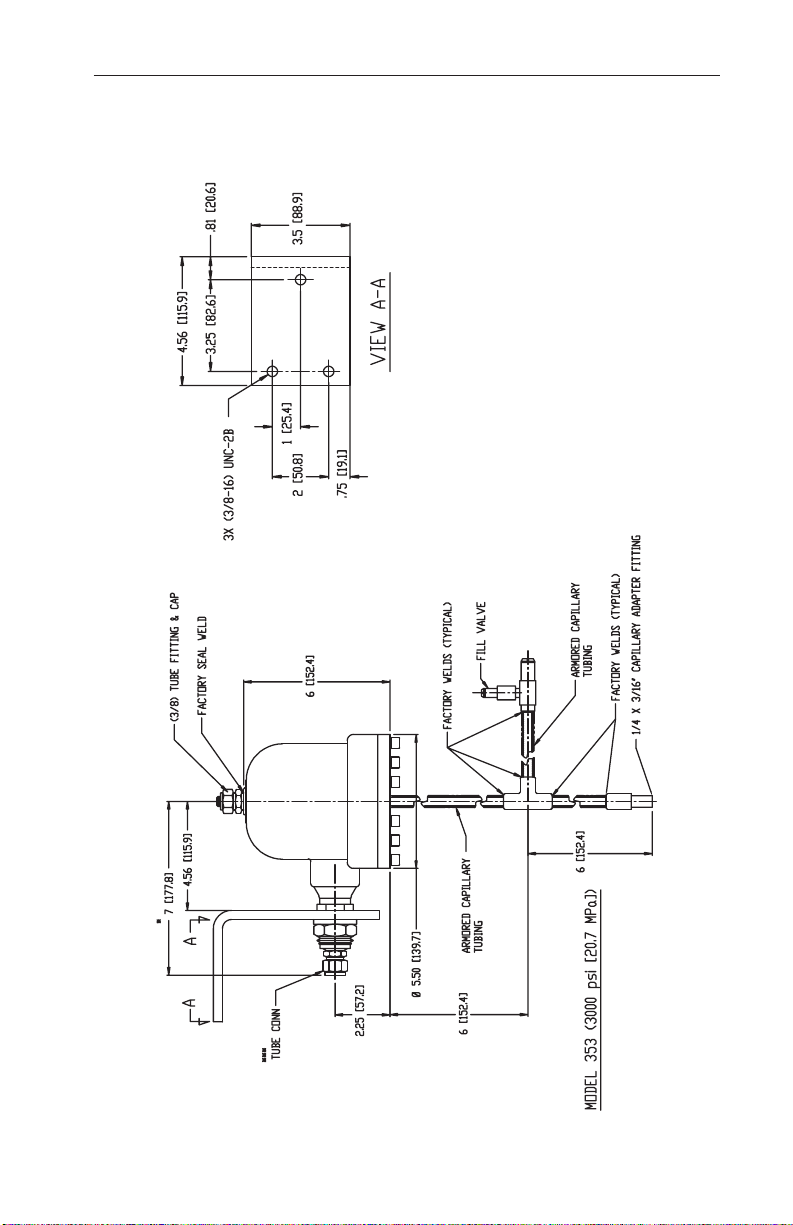
Model 351/352/353 Liquid Level Systems Section 6
*DIMENSION VARIES WITH TUBE FITTING SIZE.
*** AVAILABLE IN 3/8, 1/2 & 3/4 TUBE SIZES. ALSO
AVAILABLE WITH 9" LONG 1" SCHEDULE 160 PIPE.
4. MOUNTING BRACKET CAN BE ROTATED OR
REVERSED AS NECESSARY TO SATISFY
INSTALLATION REQUIREMENTS.
3. TORQUE BOTTOM PLATE CAP SCREWS TO
35 FT-LB [47 N-m].
2. TORQUE MOUNTING BRACKET NUT TO
147.5 FT-LB [200 N-m].
1. ALL DIMENSIONS ARE ± 0.13 IN. [3.2 MM] UNLESS
OTHERWISE NOTED.
Figure 6.4—Model 353 sensor, 3000 psi (20.7 MPa)
31
Page 32

Section 6 Model 351/352/353 Liquid Level Systems
32
Page 33

Model 351/352/353 Liquid Level Systems Section 6
Product Warranty
A. Warranty
Cameron International Corporation (“Cameron”) warrants that at the time of shipment, the
products manufactured by Cameron and sold hereunder will be free from defects in material and workmanship, and will conform to the specications furnished by or approved by
Cameron.
B. Warranty Adjustment
1. If any defect within this warranty appears, Buyer shall notify Cameron immediately
2. Cameron agrees to repair or furnish a replacement for, but not install, any product
which within one (1) year from the date of shipment by Cameron shall, upon test and
examination by Cameron, prove defective within the above warranty.
3. No product will be accepted for return or replacement without the written authoriza-
tion of Cameron. Upon such authorization, and in accordance with instructions by
Cameron, the product will be returned shipping charges prepaid by Buyer. Replace-
ments made under this warranty will be shipped prepaid.
C. Exclusions from Warranty
1. THE FOREGOING WARRANTY IS IN LIEU OF AND EXCLUDES ALL OTHER
EXPRESSED OR IMPLIED WARRANTIES OF MERCHANTABILITY, OR FITNESS FOR A PARTICULAR PURPOSE, OR OTHERWISE.
2. Components manufactured by any supplier other than Cameron shall bear only the
warranty made by the manufacturer of that product, and Cameron assumes no respon-
sibility for the performance or reliability of the unit as a whole.
3. “In no event shall Cameron be liable for indirect, incidental, or consequential dam-
ages nor shall the liability of Cameron arising in connection with any products sold
hereunder (whether such liability arises from a claim based on contract, warranty, tort,
or otherwise) exceed the actual amount paid by Buyer to Cameron for the products
delivered hereunder.”
4. The warranty does not extend to any product manufactured by Cameron which has
been subjected to misuse, neglect, accident, improper installation or to use in violation
of instructions furnished by Cameron.
5. The warranty does not extend to or apply to any unit which has been repaired or
altered at any place other than at Cameron’s factory or service locations by persons
not expressly approved by Cameron.
Product Brand
Barton® is a registered trademark of Cameron International Corporation (“Cameron”).
33
Page 34

Section 6 Model 351/352/353 Liquid Level Systems
34
Page 35

35
Page 36

www.c-a-m.com/measurement
HEADQUARTERS (HOUSTON, TX)
1.281.582.9500
UNITED STATES
1.800.654-3760
CANADA
1.403.291.4814
ASIA PACIFIC
+603.7954.0145
MIDDLE EAST & NORTH AFRICA
971.4802.7700
INDIA
91.982.2431686
EUROPE, CASPIAN, RUSSIA & S. AFRICA
+44.1892.518000
LATIN AMERICA
+55.21.2172.9714
 Loading...