

USER´S MANUAL
BEDIENUNGSANLEITUNG
MANUEL D`UTILISATION
MANUAL DE USUARIO
INSTRUKCJA OBSŁUGI
MANUALE D‘ USO
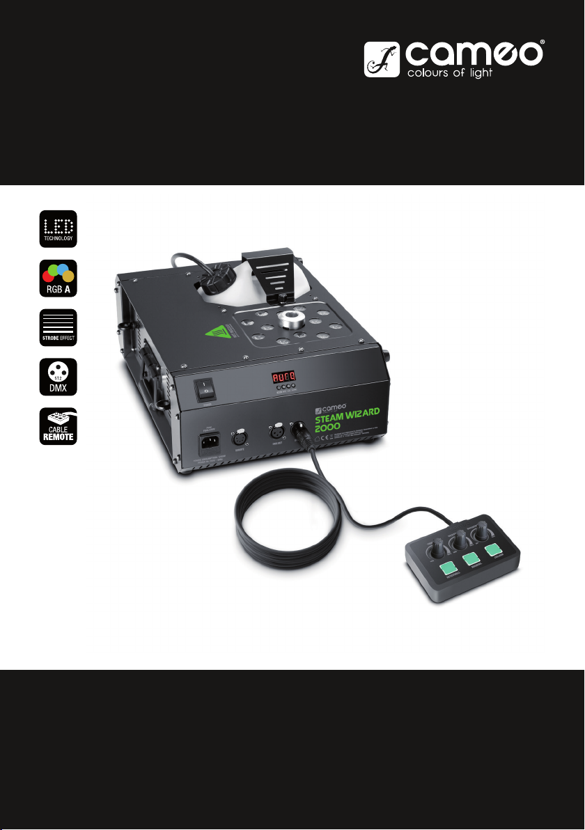
STEAM WIZARD 2000
LED FOG MACHINE
CLSW2000

CONTENTS / INHALTSVERZEICHNIS / CONTENU / CONTENIDO / TREŚĆ / CONTENUTO
ENGLISH
PREVENTIVE MEASURES 3-4
INTRODUCTION 4
CONNECTIONS, OPERATING AND DISPLAY ELEMENTS 5
OPERATION 6
CABLE REMOTE CONTROL 6-7
INSTALLATION AND ASSEMBLY 7-8
DMX TECHNOLOGY 9
TECHNICAL DATA 10
MANUFACTURER´S DECLARATIONS 10
DMX CONTROL 55
DEUTSCH
SICHERHEITSHINWEISE 11-12
EINFÜHRUNG 12
ANSCHLÜSSE, BEDIEN- UND ANZEIGEELEMENTE 13
BEDIENUNG 14
KABEL-FERNBEDIENUNG 14-15
AUFSTELLUNG UND MONTAGE 15-16
DMX TECHNIK 17
TECHNISCHE DATEN 18
HERSTELLERERKLÄRUNGEN 18
DMX STEUERUNG 55
FRANCAIS
MESURES PRÉVENTIVES 19-20
INTRODUCTION 21
RACCORDEMENTS, ÉLÉMENTS DE COMMANDE ET D’AFFICHAGE
21-22
MODE D’EMPLOI 22
TÉLÉCOMMANDE FILAIRE 23
INSTALLATION ET MONTAGE 24-25
TECHNOLOGIE DMX 25-26
CARACTÉRISTIQUES TECHNIQUES 26
DECLARATIONS 27
PILOTAGE EN MODE DMX 55
ESPAÑOL
MEDIDAS DE SEGURIDAD 28-29
INTRODUCCIÓN 30
CONEXIONES, ELEMENTOS DE MANEJO Y ELEMENTOS DE VISUALIZACIÓN 30-31
FUNCIONAMIENTO 31
MANDO A DISTANCIA POR CABLE 32
INSTALACIÓN Y MONTAJE 33-34
TECNOLOGÍA DMX 34-35
DATOS TÉCNICOS 35-36
DECLARACIÓN DEL FABRICANTE 36
CONTROL DMX 55
POLSKI
ŚRODKI OSTROŻNOŚCI 37-38
WPROWADZENIE 39
GNIAZDA, PANEL OBSŁUGI I WSKAŹNIKI 39-40
OBSŁUGA 40
PILOT PRZEWODOWY 41
USTAWIANIE I MONTAŻ 42-43
TECHNIKA DMX 43-44
DANE TECHNICZNE 44-45
DEKLARACJE PRODUCENTA 45
STEROWANIE DMX 55
ITALIANO
MISURE PRECAUZIONALI 46-47
INTRODUZIONE 48
RACCORDI, ELEMENTI DI COMANDO E DI VISUALIZZAZIONE 48-49
COMANDO 49
TELECOMANDO CON CAVO 50
INSTALLAZIONE E MONTAGGIO 51-52
TECNOLOGIA DMX 52-53
DATI TECNICI 53-54
DICHIARAZIONI DEL PRODUTTORE 54
CONTROLLO DMX 55

ENGLISH
YOU‘VE MADE THE RIGHT CHOICE!
We have designed this product to operate reliably over many years. Please read this User‘s Manual carefully, so that you can begin making
optimum use of your Cameo Light product quickly. Learn more about Cameo Light on our website WWW.CAMEOLIGHT.COM.
PREVENTIVE MEASURES
1. Please read these instructions carefully.
2. Keep all information and instructions in a safe place.
3. Follow the instructions.
4. Observe all safety warnings. Never remove safety warnings or other information from the equipment.
5. Use the equipment only in the intended manner and for the intended purpose.
6. Use only sufficiently stable and compatible stands and/or mounts (for fixed installations). Make certain that wall mounts are properly installed and
secured. Make certain that the equipment is installed securely and cannot fall down.
7. During installation, observ e the applicable safety regulations for your country.
8. Never install and operate the equipment near radiators, heat registers, ovens or other sources of heat. Make certain that the equipment is
always installed so that is cooled sufficiently and cannot overheat.
9. Never place sources of ignition, e.g., burning candles, on the equipment.
10. Ventilation slits must not be blocked.
11. This appliance is designed exclusively for indoor use, do not use this equipment in the immediate vicinity of water (does not apply
to special outdoor equipment - in this case, observe the special instructions noted below). Do not expose this equipment to flammable
materials, fluids or gases.
12. Make certain that dripping or splashed water cannot enter the equipment. Do not place containers filled with liquids, such as vases or
drinking vessels, on the equipment.
13. Make certain that objects cannot fall into the device.
14. Use this equipment only with the accessories recommended and intended by the manufacturer.
15. Do not open or modify this equipment.
16. After connecting the equipment, check all cables in order to prevent damage or accidents, e.g., due to tripping hazards.
17. During transport, make certain that the equipment cannot fall down and possibly cause property damage and personal injuries.
18. If your equipment is no longer functioning properly, if fluids or objects have gotten inside the equipment or if it has been damaged in
anot her way, switch it off immediately and unplug it from the mains outlet (if it is a powered device). This equipment may only be repaired
by authorized, qualified personnel.
19. Clean the equipment using a dry cloth.
20. Comply with all applicable disposal laws in your country. During disposal of packaging, please separate plastic and paper/cardboard.
21. Plastic bags must be kept out of reach of children.
FOR EQUIPMENT THAT CONNECTS TO THE POWER MAINS:
22. CAUTION: If the power cord of the device is equipped with an earthing contact, then it must be connected to an outlet with a protective
ground. Never deactivate the protective ground of a power cord.
23. If the equipment has been exposed to strong fluctuations in temperature (for example, after transport), do not switch it on immediately.
Moisture and condensation could damage the equipment. Do not switch on the equipment until it has reached room temperature.
24. Before connecting the equipment to the power outlet, first verify that the mains voltage and frequency match the values specified on the
equipment. If the equipment has a voltage selection switch, connect the equipment to the power outlet only if the equipment values and the
mains power values match. If the included power cord or power adapter does not fit in your wall outlet, contact your electrician.
25. Do not step on the power cord. Make certain that the power cable does not become kinked, especially at the mains outlet and/or power
adapter and the equipment connector.
26. When connecting the equipment, make certain that the power cord or power adapter is always freely accessible. Always disconnect the
equipment from the power supply if the equipment is not in use or if you want to clean the equipment. Always unplug the power cord and
power adapter from the power outlet at the plug or adapter and not by pulling on the cord. Never touch the power cord and power adapter
with wet hands.
27. Whenever possible, avoid switching the equipment on and off in quick succession because otherwise this can shorten the useful life of
the equipment.
28. IMPORTANT INFORMATION: Replace fuses only with fuses of the same type and rating. If a fuse blows repeatedly, please contact an
authorised service centre.
29. To disconnect the equipment from the power mains completely, unplug the power cord or power adapter from the power outlet.
30. If your device is equipped with a Volex power connector, the mating Volex equipment connector must be unlocked before it can be removed. However, this also means that the equipment can slide and fall down if the power cable is pulled, which can lead to personal injuries
and/or other damage. For this reason, always be careful when laying cables.
31. Unplug the power cord and power adapter from the power outlet if there is a risk of a lightning strike or before extended periods of disuse.
32. The device must only be installed in a voltage-free condition (disconnect the mains plug from the mains).
33. Dust and other debris inside the unit may cause damage. The unit should be regularly serviced or cleaned (no guarantee) depending on
ambient conditions (dust etc., nicotine, fog) by qualified personnel to prevent overheating and malfunction.
34. Please keep a distance of at least 0.5 m to any combustible materials.
35. Power cables to power multiple devices must have a cross-section of at least 1.5 mm². Within the EU, the cables must correspond to
H05VV-F, or similar. Suitable cables are offered by Adam Hall. With these cables, you can connect multiple devices via the power OUT connection to the power IN connection of an additional device. Make sure that the total current consumption of all connected devices does not
exceed the specified value on all connected devices (label on the device). Make sure to keep power cable connections as short as possible.
FRANCAISDEUTSCHENGLISH
ITALIANOPOLSKIESPAÑOL
DMX
3
CAUTION:
To reduce the risk of electric shock, do not remove cover (or back). There are no user serviceable parts
inside. Maintenance and repairs should be exclusively carried out by qualified service personnel.
ENGLISH
DEUTSCHFRANCAIS
CAUTION! HIGH VOLUMES IN AUDIO PRODUCTS!
This device is meant for professional use. Therefore, commercial use of this equipment is subject to the respectively applicable national accident
prevention rules and regulations. As a manufacturer, Adam Hall is obligated to notify you formally about the existence of potential health risks.
Hearing damage due to high volume and prolonged exposure: When in use, this product is capable of producing high sound-pressure levels (SPL)
that can lead to irreversible hearing damage in performers, employees, and audience members. For this reason, avoid prolonged exposure to
volumes in excess of 90 dB.
CAUTION! IMPORTANT INFORMATION REGARDING FOG MACHINES!
1. This product has been developed for professional use in the field of event technology and is not intended for use in the home!
ESPAÑOL
2. Use only Cameo fog fluid (water-based) and never add flammable liquid to the container!
3. Switch off the fog machine and disconnect it from the power supply before filling the container!
4. Operate the fog machine only in well-ventilated rooms!
5. Do not leave the fog machine running unattended!
6. The fog outlet nozzle becomes very hot during operation. Do not touch the outlet nozzle during operation and maintain a minimum
distance of 50cm from it! Ensure that the device has cooled down completely before cleaning or transporting it!
7. The fog mist emitted is very hot! Never direct the outlet nozzle towards people or animals! RISK OF BURNING!
8. If the fog machine is installed overhead, ensure that people or animals are not allowed directly underneath it! RISK OF BURNING!
9. Never direct the fog outlet nozzle towards open flames or flammable materials!
The warning triangle with lightning symbol indicates dangerous uninsulated voltage inside the unit, which may cause an
electrical shock.
The warning triangle with exclamation mark indicates important operating and maintenance instructions.
Warning! This symbol indicates a hot surface. Certain parts of the housing can become hot during operation. After use, wait for
a cool-down period of at least 10 minutes before handling or transporting the device.
Warning! This device is designed for use below 2000 metres in altitude.
Warning! This product is not intended for use in tropical climates.
INTRODUCTION
LED FOG MACHINE
CLSW2000
CONTROL FUNCTIONS
4-channel DMX control
ITALIANO POLSKI
Cable remote control
FEATURES
LED fog machine with 12 x 10 W 4-in-1 RGBA LEDs, pyrotechnic-similar effects, DMX-512 control, overheating protection and empty
canister warning, rubber feet, traverse installation at any angle, safety eyelets, cable remote control included, operating voltage 230 V AC /
50 Hz, power consumption 1200 W.
DMX
4
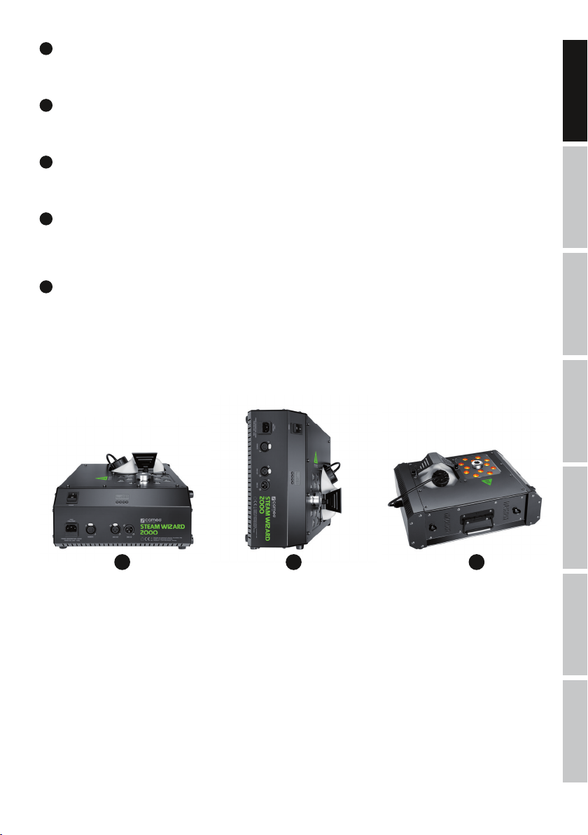
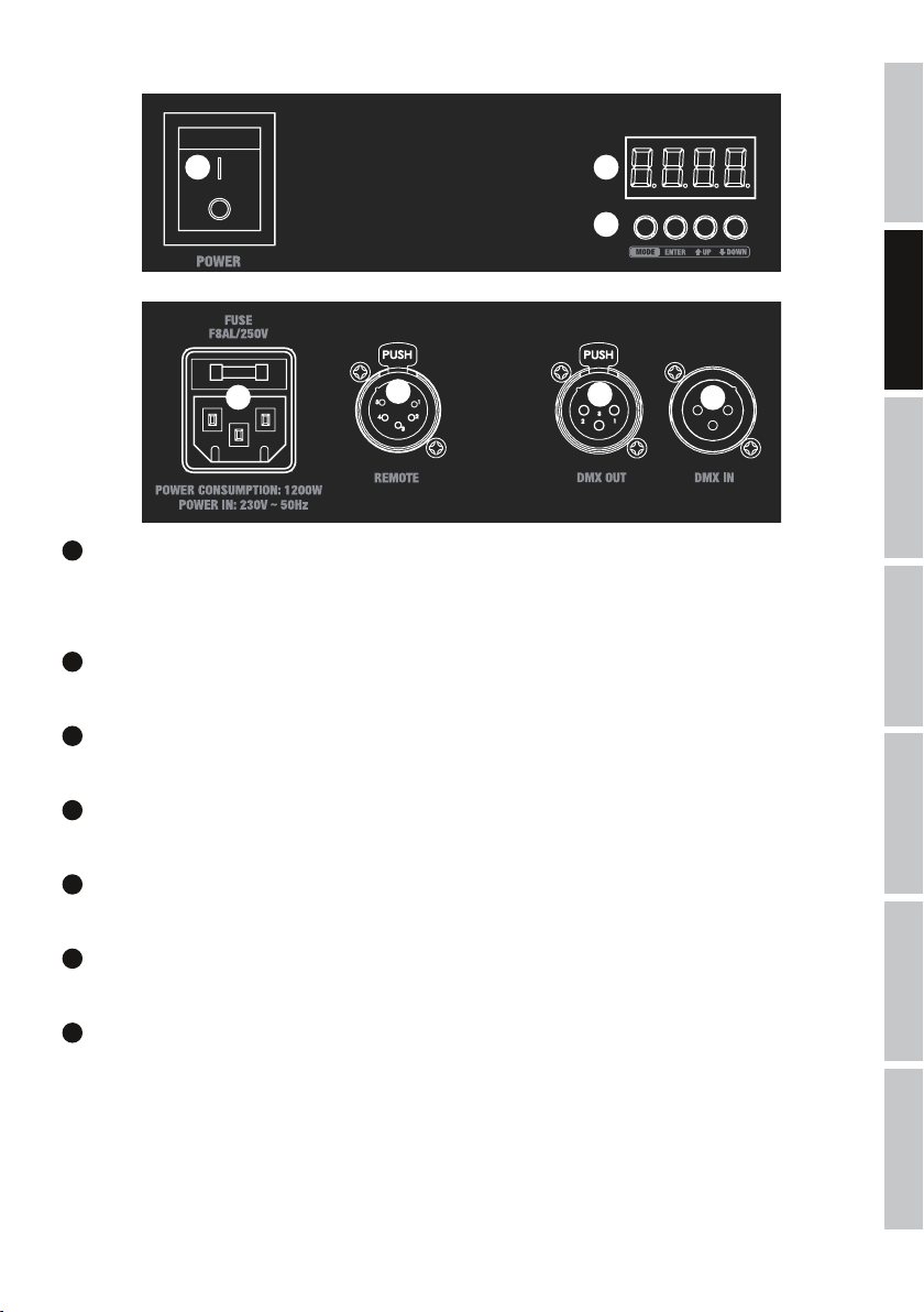
CONNECTIONS, OPERATING AND DISPLAY ELEMENTS
2 6
7
1
1
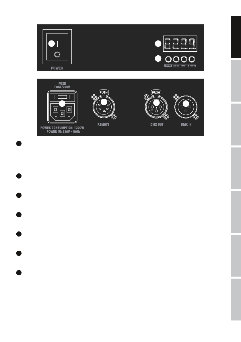
POWER IN
IEC mains socket with built-in fuse holder. A suitable power cable is included.
IMPORTANT:
of repeated fuse failure, please contact an authorised service centre.
2
On / Off switch for power supply to the device.
3
5-pin XLR socket for connection of the cable remote control (included).
4
Male 3-pin XLR socket for connection to a DMX control device (e.g. DMX console).
5
Female 3-pin XLR socket for sending the DMX control signal.
6
The four-digit LED display shows the operating status, mode and other system information.
Replace the fuse only with a fuse of the same type and of the same value according to the stamp on the device! In the event
POWER
REMOTE
DMX IN
DMX OUT
LED DISPLAY
3
5
4
FRANCAISDEUTSCHENGLISH
ITALIANOPOLSKIESPAÑOL
7
CONTROL BUTTONS
MODE: Selection of menu items. Move up one level in the menu structure.
ENTER: Confirm value changes.
UP and DOWN: Changing DMX address and settings.
DMX
5
OPERATION
Switch off the LED fog machine and disconnect it from the power supply before filling the container! Fill the container of the LED fog
machine only with Cameo fog fluid (preferably Cameo Fast Fluid) and close it carefully. The fog machine is ready for operation a few minutes
after switching on (approx. 5 minutes). It features a canister light (LED) and a 4-digit LED display to provide information on the operating
status. Display elements canister light and display are activated in the factory settings.
ENGLISH
1. During warm-up phase of the evaporator, the canister is permanently lit up in red, the display shows "uP" and the device is not ready for
operation.
2. Whilst ready for operation, the canister is constantly lit blue, and depending upon settings, the display will show either "rEAd" (control via
cable remote control), or the currently configured DMX start address (control via DMX controller).
3. If the fog fluid in the container is all used up, the canister light will start to flash red after approximately 2 minutes, two minus symbols
will be shown in the display and the LED fog machine will switch to error mode. Switch off the unit and disconnect it from the mains. Fill the
container with fog fluid and switch the unit back on. Follow the same procedure if you notice that the fluid has all been used before the fog
machine switches to error mode.
DEUTSCHFRANCAIS
If there is a DMX signal to the device, the DMX mode is activated automatically and the currently configured DMX start address will appear
in the display. The cable remote control is disabled in this case. If there is no DMX signal, the LED fog machine can be controlled with the
supplied cable remote control.
The evaporator is LED fog machine ready (ready).
CONFIGURE DMX START ADDRESS
Press the MODE button repeatedly until "Addr" appears in the display. Now press ENTER and configure the DMX start address using the UP
and DOWN buttons as required (001 - 509). Confirm your entry with ENTER.
ADJUSTMENT OF DISPLAY ELEMENTS
In some cases, canister lighting and LED display can have a disturbing effect and can therefore be switched off (the empty canister warning
ESPAÑOL
is excluded and will be activated in the event of an error).
Press the MODE button repeatedly until the display shows "dArk", press ENTER and select the desired setting using the UP and DOWN buttons
(on = container lighting switched off, display switched off after approx. 15 seconds / oFF = container lighting and display permanently active).
Confirm your entry with ENTER.
Control via cable remote control.
-> ENTER -> UP/DOWN
-> ENTER -> UP/DOWN
-
/
LED fog machine ready,
DMX signal is present.
-> ENTER
<- MODE
-> ENTER
<- MODE
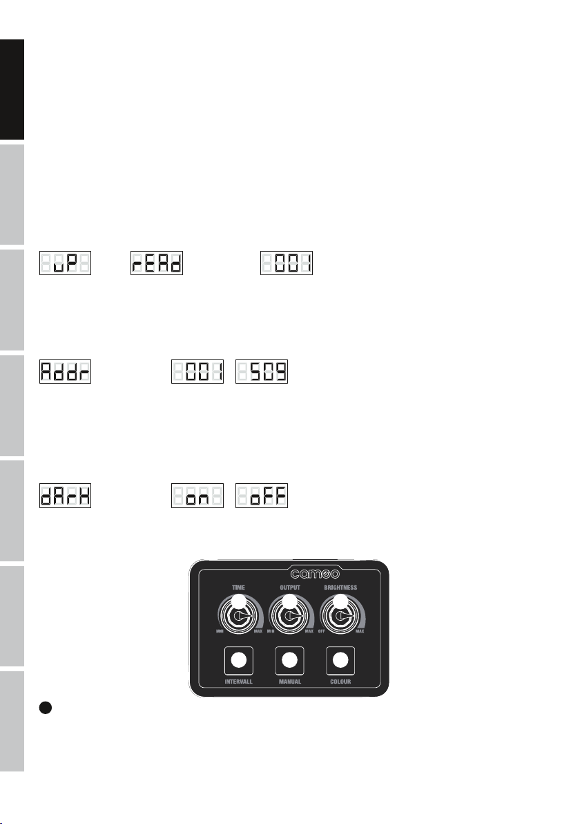
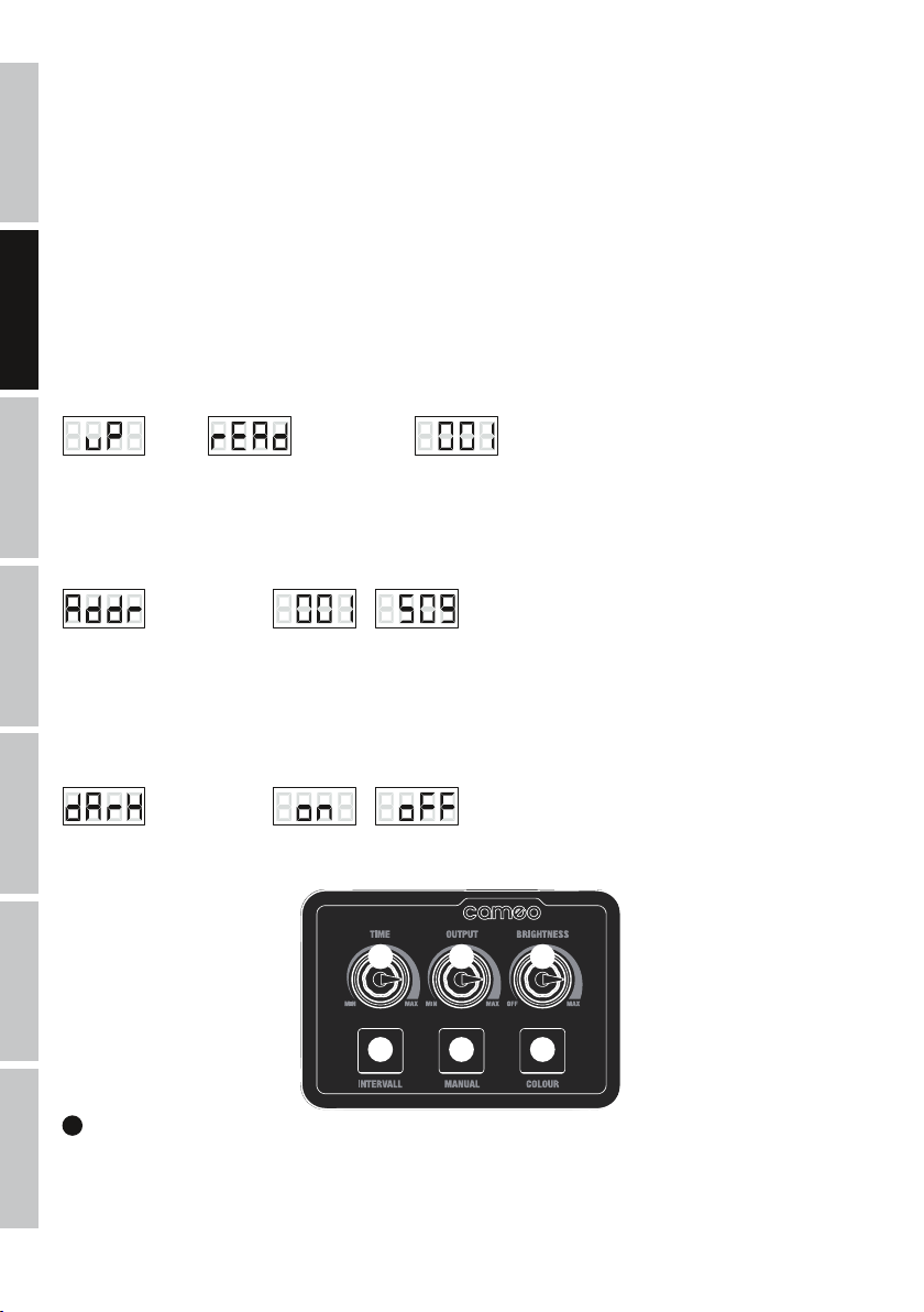
CABLE REMOTE CONTROL
2 4 6
ITALIANO POLSKI
1 3 5
1
INTERVAL
Interval function for fog output and simultaneous illumination of LEDs. Press the button to start the interval function and again to quit. The
DMX
fog burst and LED illumination period is approximately 2 seconds. Configure the time interval between bursts with the TIME dial. If the
interval function is activated, the indicator LED on the button is lit. During fog bursts, “FoG” appears on the display.
6
2
TIME
Knob for adjustment of time between bursts of the interval function (all the way to the left = continuous bursts / 0 second interval, all the way to
the right = approx. 60 seconds interval). An integrated LED indicator lights up as soon as the heating-up phase of the evaporator is complete.
3
MANUAL
Button for manual triggering of the combined effect. Fog burst and LED illumination continues for as long as the button is pressed. When the
button is pressed the indicator LED in the button is lit. During fog bursts, “FoG” appears on the display.
4
OUTPUT
Knob to adjust the fog burst density quantity (all the way to the left = fog output disabled / 0%, all the way to the right = maximum fog
density / 100%). An integrated LED indicator lights up as soon as the heating-up phase of the evaporator is complete.
5
COLOUR
Button to adjust the LED light colour. Press and hold the button for approximately 1 second until the LEDs are turned on, then press briefly
and repeatedly to select the desired colour (14 colour presets and automatic colour change). The LEDs are lit for approx. 5 seconds, as is
the LED indicator in the button.
6
BRIGHTNESS
Knob to adjust brightness effect (all the way to the left = blackout / 0%, all the way to the right = maximum brightness / 100%). An integrated
LED indicator lights up as soon as the heating-up phase of the evaporator is complete.
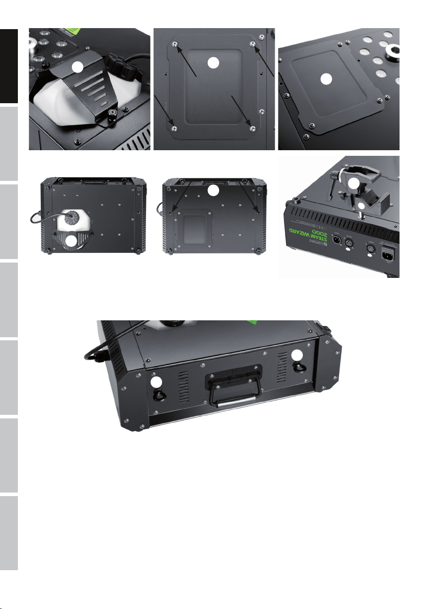
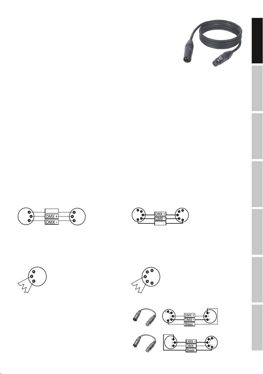
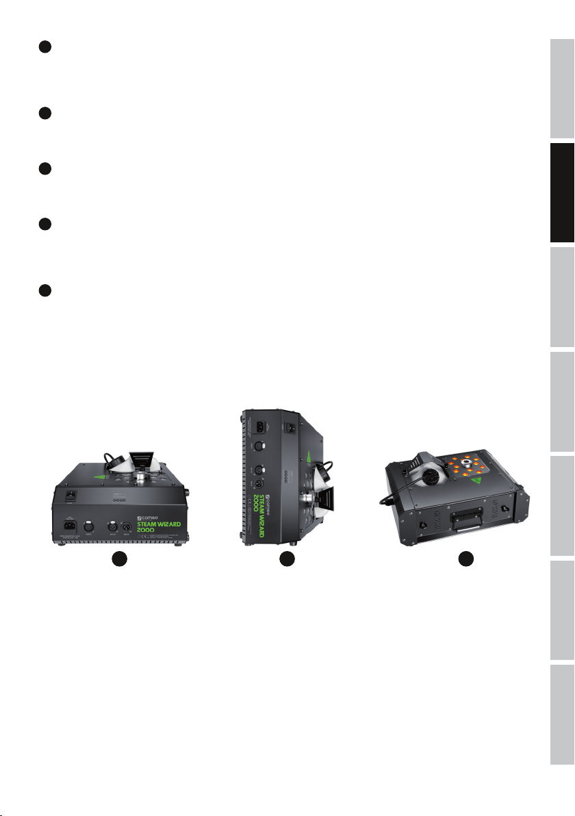
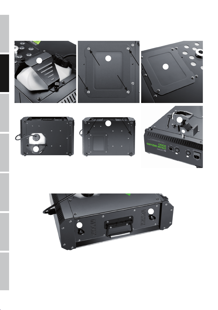
INSTALLATION
For installation on a level surface, the LED fog machine features four rubber feet on the base (Fig. A, vertical fog output) and on one side (Fig
B, horizontal fog output). For convenient transportation, a folding handle is located on the side of the housing (Fig. C).
FRANCAISDEUTSCHENGLISH
A B C
Because the LED fog machine can be installed at any desired angle on a traverse, it features a top-or-bottom-loading canister tray. Load
the canister tray from the bottom if the LED fog machine is installed at an angle greater than 90°. To do this, remove the canister retaining
clamp (Fig. D), remove the canister and remove the
canister shelves from the bottom of the housing using a suitable tool (Fig. E, 4 screws, screwdriver PH2). Now install the canister shelves on
the top side of the housing in the designated position (Fig. F), place the canister in the canister tray and secure it with the canister retaining
clamp (Fig. G). Make sure that the canister is held in place firmly.
ITALIANOPOLSKIESPAÑOL
DMX
7
ENGLISH
DEUTSCHFRANCAIS
D
E
F
H
G
For traverse installation, two M10 threads are located on the base of the housing (Fig. H) to receive the traverse mounting bolts. (Fig. I, not included).
Secure the device via the integrated safety eyelets (Fig. J) and appropriate securing cables (not included). IMPORTANT: Overhead installation must
only be carried out by qualified personnel. When installing, please refer to the points under “CAUTION! IMPORTANT INFORMATION REGARDING FOG
MACHINES!” in this manual.
ESPAÑOL
J
J
I
ITALIANO POLSKI
DMX
8
DMX TECHNOLOGY
DMX-512
DMX (Digital Multiplex) is the designation for a universal transmission protocol for
communications between corresponding devices and controllers. A DMX controller sends
DMX data to the connected DMX device(s). The DMX data is always transmitted as a serial
data stream that is forwarded from one connected device to the next via the "DMX IN" and
"DMX OUT" connectors (XLR plug-type connectors) that are found on every DMX-capable
device, provided the maximum number of devices does not exceed 32 units. The last device
in the chain needs to be equipped with a terminator (terminating resistor).
DMX CONNECTION
DMX is the common "language" via which a very wide range of types and models of equipment from various manufacturers can
be connected with one another and controlled via a central controller, provided that all of the devices and the controller are DMX
compatible. For optimum data transmission, it is necessary to keep the connecting cables between the individual devices as short as
possible. The order in which the devices are integrated in the DMX network has no influence on the addresses. Thus the device with
the DMX address 1 can be located at any position in the (serial) DMX chain: at the beginning, at the end or somewhere in the middle.
If the DMX address 1 is assigned to a device, the controller "knows" that it should send all data allocated to address 1 to this device
regardless of its position in the DMX network.
SERIAL CONNECTION OF MULTIPLE LIGHTS
1. Connect the male XLR connector (3-pin or 5-pin) of the DMX cable to the DMX output (female XLR socket) of the first DMX device
(e.g. DMX-Controller).
2. Connect the female 3-pin XLR connector of the DMX cable connected to the first projector to the DMX input (male 3-pin socket)
of the next DMX device. In the same way, connect the DMX output of this device to the DMX input of the next device and repeat until
all devices have been connected. Please note that as a rule, DMX devices are connected in series and connections cannot be shared
without active splitters. The maximum number of DMX devices in a DMX chain should not exceed 32 units.
The Adam Hall 3 STAR, 4 STAR, and 5 STAR product ranges include an extensive selection of suitable cables.
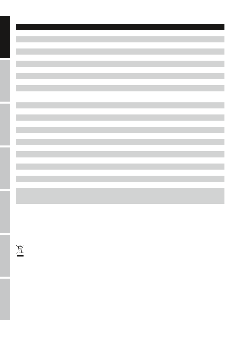
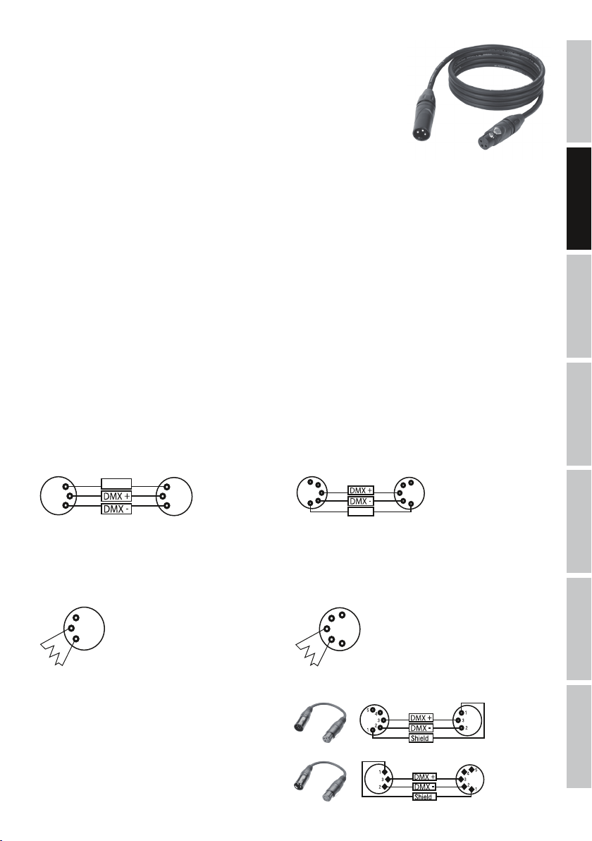
DMX CABLES
When fabricating your own cables, always observe the illustrations on this page. Never connect the shielding of the cable to the ground
contact of the plug, and always make certain that the shielding does not come into contact with the housing of the XLR plug. If the shielding
is connected to the ground, this can lead to short-circuiting and system malfunctions.
Pin Assignment
DMX cable with 3-pin XLR connectors: DMX cable with 5-pin XLR connectors (pin 4 and 5 are not used):
1
3
2
Shield
1
3
2
5
4
3
2
1
Shield
DMX TERMINATORS (TERMINATING RESISTORS)
To prevent system errors, the last device in a DMX chain needs to be equipped with a terminating resistor (120 ohm, 1/4 Watt).
3-pin XLR connector with a terminating resistor: K3DMXT3
5-pin XLR connector with a terminating resistor: K3DMXT5
Pin Assignment
3-pin XLR connector: 5-pin XLR connector:
1
3
2
5
4
3
2
1
5
4
3
2
1
FRANCAISDEUTSCHENGLISH
ITALIANOPOLSKIESPAÑOL
DMX ADAPTER
The combination of DMX devices with 3-pin connectors and DMX devices with 5-pin connectors in a DMX chain is possible with suitable adapters.
Pin Assignment
DMX Adapter 5-pin XLR male to 3-pin XLR female: K3DGF0020
Pins 4 and 5 are not used.
Pin Assignment
DMX Adapter 3-pin XLR male to 5-pin XLR female: K3DHM0020
Pins 4 and 5 are not used.
DMX
9
TECHNICAL DATA
Model name: CLSW2000
Product type: Effect fog machine
Type: Fog generator operating on evaporation principle combined with LED spotlights
ENGLISH
Warm-up time: Approximately 5 minutes
Colour spectrum LED: RGBA
Number of LEDs: 12
LED type: 10 W 4-in-1
DMX input: 3-pin male XLR
DMX output: 3-pin female XLR
DMX mode: 4 Channel
DMX functions: fog density, dimmer, strobe, colour macros, colour change, colour blend
DEUTSCHFRANCAIS
Cable remote control functions: fog density, dimmer, colour macros, colour change, intermittent function, manual
Control: DMX512
Controls: mode, enter, up, down, cable remote control
Display elements: 4-digit LED display, canister light
Operating voltage: 230 V AC / 50 Hz
Power consumption: 1200 W
Overheating protection: Heating element with thermostat
Power connection: IEC input
Fuse: F8AL / 250 V (5 x 20 mm)
Ambient temperature (in operation): 5°C - 40°C
Relative air humidity: < 85%, non-condensing
Housing material: Metal
Housing colour: black
ESPAÑOL
Dimensions (W x H x D): 455 x 197 x 318mm.
Weight (without canister): 8.3kg
Additional features: carrying handle, canister and cap with pressure compensation valve and suction hose
operation
included, 2 x M10 threads, 2 x safety eyelets, installation at any angle, canister compartment on the top or bottom, 8 rubber feet, cable remote control with 10m cable
MANUFACTURER´S DECLARATIONS
MANUFACTURER‘S WARRANTY & LIMITATIONS OF LIABILITY
You can find our current warranty conditions and limitations of liability at: http://www.adamhall.com/media/shop/downloads/documents/
manufacturersdeclarations.pdf. To request warranty service for a product, please contact Adam Hall GmbH, Daimler Straße 9, 61267 Neu
Anspach / Email: Info@adamhall.com / +49 (0)6081 / 9419-0.
CORRECT DISPOSAL OF THIS PRODUCT
(valid in the European Union and other European countries with a differentiated waste collection system)
This symbol on the product, or on its documents indicates that the device may not be treated as household waste. This is to avoid
environmental damage or personal injury due to uncontrolled waste disposal. Please dispose of this product separately from other waste
ITALIANO POLSKI
and have it recycled to promote sustainable economic activity. Household users should contact either the retailer where they purchased
this product, or their local government office, for details on where and how they can recycle this item in an environmentally friendly manner.
Business users should contact their supplier and check the terms and conditions of the purchase contract. This product should not be mixed
with other commercial waste for disposal.
CE Compliance
Adam Hall GmbH states that this product meets the following guidelines (where applicable):
R&TTE (1999/5/EC) or RED (2014/53/EU) from June 2017
Low voltage directive (2014/35/EU)
DMX
EMV directive (2014/30/EU)
RoHS (2011/65/EU)
The complete declaration of conformity can be found at www.adamhall.com.
Furthermore, you may also direct your enquiry to info@adamhall.com.
10

DEUTSCH
SIE HABEN DIE RICHTIGE WAHL GETROFFEN!
Dieses Gerät wurde unter hohen Qualitätsanforderungen entwickelt und gefertigt, um viele Jahre einen reibungslosen Betrieb zu gewährleisten. Bitte lesen Sie diese Bedienungsanleitung sorgfältig, damit Sie Ihr neues Produkt von Cameo Light schnell und optimal einsetzen
können. Weitere Informationen über Cameo Light erhalten Sie auf unserer Website WWW.CAMEOLIGHT.COM.
SICHERHEITSHINWEISE
1. Lesen Sie diese Anleitung bitte sorgfältig durch.
2. Bewahren Sie alle Informationen und Anleitungen an einem sicheren Ort auf.
3. Befolgen Sie die Anweisungen.
4. Beachten Sie alle Warnhinweise. Entfernen Sie keine Sicherheitshinweise oder andere Informationen vom Gerät.
5. Verwenden Sie das Gerät nur in der vorgesehenen Art und Weise.
6. Verwenden Sie ausschließlich stabile und passende Stative bzw. Befestigungen (bei Festinstallationen). Stellen Sie sicher, dass Wandhalterungen
ordnungsgemäß installiert und gesichert sind. Stellen Sie sicher, dass das Gerät sicher installiert ist und nicht herunterfallen kann.
7. Beachten Sie bei der Installation die für Ihr Land geltenden Sicherheitsvorschriften.
8. Installieren und betreiben Sie das Gerät nicht in der Nähe von Heizkörpern, Wärmespeichern, Öfen oder sonstigen Wärmequellen. Sorgen
Sie dafür, dass das Gerät immer so installiert ist, dass es ausreichend gekühlt wird und nicht überhitzen kann.
9. Platzieren Sie keine Zündquellen wie z.B. brennende Kerzen auf dem Gerät.
10. Lüftungsschlitze dürfen nicht blockiert werden.
11. Das Gerät wurde ausschließlich für die Verwendung in Innenräumen entwickelt, betreiben Sie das Gerät nicht in unmittelbarer Nähe von
Wasser (gilt nicht für spezielle Outdoor Geräte - beachten Sie in diesem Fall bitte die im Folgenden vermerkten Sonderhinweise). Bringen Sie
das Gerät nicht mit brennbaren Materialien, Flüssigkeiten oder Gasen in Berührung.
12. Sorgen Sie dafür, dass kein Tropf- oder Spritzwasser in das Gerät eindringen kann. Stellen Sie keine mit Flüssigkeit gefüllten Behältnisse
wie Vasen oder Trinkgefäße auf das Gerät.
13. Sorgen Sie dafür, dass keine Gegenstände in das Gerät fallen können.
14. Betreiben Sie das Gerät nur mit dem vom Hersteller empfohlenen und vorgesehenen Zubehör.
15. Öffnen Sie das Gerät nicht und verändern Sie es nicht.
16. Überprüfen Sie nach dem Anschluss des Geräts alle Kabelwege, um Schäden oder Unfälle, z. B. durch Stolperfallen zu vermeiden.
17. Achten Sie beim Transport darauf, dass das Gerät nicht herunterfallen und dabei möglicherweise Sach- und Personenschäden verursachen kann.
18. Wenn Ihr Gerät nicht mehr ordnungsgemäß funktioniert, Flüssigkeiten oder Gegenstände in das Geräteinnere gelangt sind, oder das Gerät
anderweitig beschädigt wurde, schalten Sie es sofort aus und trennen es von der Netzsteckdose (sofern es sich um ein aktives Gerät handelt).
Dieses Gerät darf nur von autorisiertem Fachpersonal repariert werden.
19. Verwenden Sie zur Reinigung des Geräts ein trockenes Tuch.
20. Beachten Sie alle in Ihrem Land geltenden Entsorgungsgesetze. Trennen Sie bei der Entsorgung der Verpackung bitte Kunststoff und
Papier bzw. Kartonagen voneinander.
21. Kunststoffbeutel müssen außer Reichweite von Kindern aufbewahrt werden.
BEI GERÄTEN MIT NETZANSCHLUSS:
22. ACHTUNG: Wenn das Netzkabel des Geräts mit einem Schutzkontakt ausgestattet ist, muss es an einer Steckdose mit Schutzleiter
angeschlossen werden. Deaktivieren Sie niemals den Schutzleiter eines Netzkabels.
23. Schalten Sie das Gerät nicht sofort ein, wenn es starken Temperaturschwankungen ausgesetzt war (beispielsweise nach dem Transport).
Feuchtigkeit und Kondensat könnten das Gerät beschädigen. Schalten Sie das Gerät erst ein, wenn es Zimmertemperatur erreicht hat.
24. Bevor Sie das Gerät an die Steckdose anschließen, prüfen Sie zuerst, ob die Spannung und die Frequenz des Stromnetzes mit den auf
dem Gerät angegebenen Werten übereinstimmen. Verfügt das Gerät über einen Spannungswahlschalter, schließen Sie das Gerät nur an die
Steckdose an, wenn die Gerätewerte mit den Werten des Stromnetzes übereinstimmen. Wenn das mitgelieferte Netzkabel bzw. der mitgelieferte Netzadapter nicht in Ihre Netzsteckdose passt, wenden Sie sich an Ihren Elektriker.
25. Treten Sie nicht auf das Netzkabel. Sorgen Sie dafür, dass spannungsführende Kabel speziell an der Netzbuchse bzw. am Netzadapter
und der Gerätebuchse nicht geknickt werden.
26. Achten Sie bei der Verkabelung des Geräts immer darauf, dass das Netzkabel bzw. der Netzadapter stets frei zugänglich ist. Trennen Sie
das Gerät stets von der Stromzuführung, wenn das Gerät nicht benutzt wird, oder Sie das Gerät reinigen möchten. Ziehen Sie Netzkabel und
Netzadapter immer am Stecker bzw. am Adapter und nicht am Kabel aus der Steckdose. Berühren Sie Netzkabel und Netzadapter niemals
mit nassen Händen.
27. Schalten Sie das Gerät möglichst nicht schnell hintereinander ein und aus, da sonst die Lebensdauer des Geräts beeinträchtigt werden könnte.
28. WICHTIGER HINWEIS: Ersetzen Sie Sicherungen ausschließlich durch Sicherungen des gleichen Typs und Wertes. Sollte eine Sicherung
wiederholt auslösen, wenden Sie sich bitte an ein autorisiertes Servicezentrum.
29. Um das Gerät vollständig vom Stromnetz zu trennen, entfernen Sie das Netzkabel bzw. den Netzadapter aus der Steckdose.
30. Wenn Ihr Gerät mit einem Volex-Netzanschluss bestückt ist, muss der passende Volex-Gerätestecker entsperrt werden, bevor er entfernt
werden kann. Das bedeutet aber auch, dass das Gerät durch ein Ziehen am Netzkabel verrutschen und herunterfallen kann, wodurch Personen verletzt werden und/oder andere Schäden auftreten können. Verlegen Sie Ihre Kabel daher immer sorgfältig.
31. Entfernen Sie Netzkabel und Netzadapter aus der Steckdose bei Gefahr eines Blitzschlags oder wenn Sie das Gerät länger nicht verwenden.
32. Das Gerät darf nur im spannungsfreien Zustand (Trennung des Netzsteckers vom Stromnetz) installiert werden.
33. Staub und andere Ablagerungen im Inneren des Geräts können es beschädigen. Das Gerät sollte je nach Umgebungsbedingungen
(Staub, Nikotin, Nebel etc.) regelmäßig von qualifiziertem Fachpersonal gewartet bzw. gesäubert werden (keine Garantieleistung),
um Überhitzung und Fehlfunktionen zu vermeiden.
34. Der Abstand zu brennbaren Materialien muss mindestens 0,5 m betragen.
35. Netzleitungen zur Spannungsversorgung mehrerer Geräte müssen mindestens 1,5 mm² Aderquerschnitt aufweisen. In der EU müssen
FRANCAISDEUTSCHENGLISH
ITALIANOPOLSKIESPAÑOL
DMX
11
die Leitungen H05VV-F, oder gleichartig, entsprechen. Geeignete Leitungen werden von Adam Hall angeboten. Mit diesen Leitungen können
Sie mehrere Geräte über den Power out Anschluss mit dem Power IN Anschluss eines weiteren Gerätes verbinden. Beachten Sie, dass die
gesamte Stromaufnahme aller angeschlossenen Geräte den vorgegebenen Wert nicht überschreitet (Aufdruck auf dem Gerät). Achten Sie
darauf, Netzleitungen so kurz wie möglich zu halten.
ENGLISH
Das gleichseitige Dreieck mit Blitzsymbol warnt vor nichtisolierten, gefährlichen Spannungen im Geräteinneren, die einen
elektrischen Schlag verursachen können.
Das gleichseitige Dreieck mit Ausrufungszeichen kennzeichnet wichtige Bedienungs- und Wartungshinweise.
ACHTUNG
Entfernen Sie niemals die Abdeckung, da sonst das Risiko eines elektrischen Schlages besteht. Im
Inneren des Geräts befinden sich keine Teile, die vom Bediener repariert oder gewartet werden können.
Lassen Sie Wartung und Reparaturen ausschließlich von qualifiziertem Servicepersonal durchführen.
DEUTSCHFRANCAIS
Warnung! Dieses Symbol kennzeichnet heiße Oberflächen. Während des Betriebs können bestimmte Teile des Gehäuses heiß
werden. Berühren oder transportieren Sie das Gerät nach einem Einsatz erst nach einer Abkühlzeit von mindestens 10 Minuten.
Warnung! Dieses Gerät ist für eine Nutzung bis zu einer Höhe von maximal 2000 Metern über dem Meeresspiegel bestimmt.
Warnung! Dieses Gerät ist nicht für den Einsatz in tropischen Klimazonen bestimmt.
VORSICHT! WICHTIGE HINWEISE IN BEZUG AUF LICHT-PRODUKTE!
1. Das Produkt ist für den professionellen Einsatz im Bereich der Veranstaltungstechnik entwickelt worden und ist nicht für die Raumbeleuchtung in
Haushalten geeignet.
2. Blicken Sie niemals, auch nicht kurzzeitig, direkt in den Lichtstrahl.
3. Blicken Sie niemals mit optischen Geräten wie Vergrößerungsgläsern in den Lichtstrahl.
4. Stroboskopeffekte können unter Umständen bei empfindlichen Menschen epileptische Anfälle auslösen! Epilepsiekranke Menschen
ESPAÑOL
sollten daher unbedingt Orte meiden, an denen Stroboskope eingesetzt werden.
VORSICHT! WICHTIGE HINWEISE IN BEZUG AUF NEBELMASCHINEN!
1. Das Produkt ist für den professionellen Einsatz im Bereich der Veranstaltungstechnik entwickelt worden und ist nicht für den Betrieb in
Haushalten geeignet!
2. Verwenden Sie ausschließlich Cameo Nebelfluid (wasserbasierend) und füllen Sie niemals brennbare Flüssigkeiten in den Kanister!
3. Schalten Sie die Nebelmaschine aus und trennen sie vom Netz, bevor Sie den Kanister befüllen!
4. Betreiben Sie die Nebelmaschine ausschließlich in gut belüfteten Räumen!
5. Betreiben Sie die Nebelmaschine niemals unbeaufsichtigt!
6. Die Nebelaustrittsdüse wird im Betrieb sehr heiß. Berühren Sie die Austrittsdüse nicht während des Betriebs und halten einen Mindestabstand
von 50cm ein! Stellen Sie vor dem Reinigen und Transportieren sicher, dass das Gerät vollständig abgekühlt ist!
7. Der austretende Nebel ist sehr heiß! Richten Sie die Austrittsdüse niemals auf Personen und Tiere! VERBRENNUNGSGEFAHR!
8. Achten Sie darauf, dass sich Personen und Tiere bei der Überkopfmontage nicht direkt unterhalb von Nebelmaschinen aufhalten dürfen!
VERBRENNUNGSGEFAHR!
9. Richten Sie die Nebelaustrittsdüse niemals auf offene Flammen und brennbare Materialien!
EINFÜHRUNG
LED NEBELMASCHINE
ITALIANO POLSKI
CLSW2000
STEUERUNGSFUNKTIONEN
4-Kanal DMX-Steuerung
Kabel-Fernbedienung
DMX
EIGENSCHAFTEN
LED Nebelmaschine mit 12 x 10W 4in1 RGBA LEDs, Effekt ähnlich Pyrotechnik, DMX-512 Steuerung, Überhitzungsschutz und Warnung bei
leerem Kanister, Gummifüße, Traversenmontage in beliebigem Winkel, Safety Schraubösen, Kabel-Fernbedienung inklusive, Betriebsspannung
230V AC / 50Hz, Leistungsaufnahme 1200W.
12
ANSCHLÜSSE, BEDIEN- UND ANZEIGEELEMENTE
2 6
7
1
1
POWER IN
IEC Netzbuchse mit integriertem Sicherungshalter. Ein geeignetes Netzkabel befindet sich im Lieferumfang.
WICHTIGER HINWEIS: Ersetzen Sie die Sicherung ausschließlich durch eine Sicherung des gleichen Typs und mit gleichen Werten entsprechend
des Aufdrucks auf dem Gerät! Sollte die Sicherung wiederholt auslösen, wenden Sie sich bitte an ein autorisiertes Servicezentrum.
2
POWER
Ein- / Ausschalter für die Spannungszufuhr des Geräts.
3
REMOTE
5-polige XLR-Buchse zum Anschließen der Kabel-Fernbedienung (im Lieferumfang).
4
DMX IN
Männliche 3-Pol XLR-Buchse zum Anschließen eines DMX-Kontrollgeräts (z.B. DMX-Pult).
5
DMX OUT
Weibliche 3-Pol XLR-Buchse zum Weiterleiten des DMX-Steuersignals.
6
LED DISPLAY
Das vierstellige LED-Display zeigt den Betriebszustand, die Betriebsart und weitere Systeminformationen an.
3
5
4
FRANCAISDEUTSCHENGLISH
ITALIANOPOLSKIESPAÑOL
7
BEDIENTASTER
MODE: Auswahl der Menüpunkte. In der Menüstruktur eine Ebene höher gelangen.
ENTER: Bestätigen von Wertänderungen.
UP und DOWN: Ändern von DMX-Adresse und Einstellungen.
DMX
13
BEDIENUNG
Schalten Sie die LED-Nebelmaschine aus und trennen sie stets vom Netz, bevor Sie den Kanister befüllen. Befüllen Sie den Kanister der
LED-Nebelmaschine ausschließlich mit Cameo Nebelfluid (vorzugsweise Cameo Fast Fluid) und verschließen ihn sorgfältig. Wenige Minuten
nach dem Einschalten ist die LED-Nebelmaschine betriebsbereit (ca. 5 Minuten). Sie verfügt über eine Kanisterbeleuchtung (LED) und das
4-stellige LED-Display, die über den Betriebszustand Auskunft geben. In der Einstellung ab Werk sind die Anzeigeelemente Kanisterbeleuchtung
ENGLISH
und Display aktiviert:
1. Während der Aufheizphase des Verdampfers leuchtet der Kanister permanent rot, im Display wird „uP“ angezeigt und das Gerät ist nicht
betriebsbereit.
2. Während der Betriebsbereitschaft leuchtet der Kanister permanent blau, im Display wird, je nach Ansteuerung, „rEAd“ (Ansteuerung via
Kabel-Fernbedienung), oder die aktuell eingestellte DMX-Startadresse angezeigt (Ansteuerung via DMX-Controller).
3. Ist das Nebelfluid im Kanister verbraucht, fängt die Kanisterbeleuchtung nach ca. 2 Minuten an rot zu blinken, im Display blinken zwei
Minuszeichen und die LED-Nebelmaschine wechselt in den Fehlermodus. Schalten Sie das Gerät aus und trennen es vom
Netz, befüllen den Kanister mit Nebelfluid und schalten das Gerät wieder ein. Gehen Sie in gleicher Weise vor, falls Sie bevor
die Nebelmaschine in den Fehlermodus wechselt, bemerken, dass das Nebelfluid verbraucht ist.
DEUTSCHFRANCAIS
Liegt ein DMX-Signal am Gerät an, wird automatisch die DMX-Betriebsart aktiviert und die aktuell eingestellte DMX-Startadresse wird im
Display angezeigt. Die Steuerung via Kabel-Fernbedienung ist in diesem Fall deaktiviert. Liegt kein DMX-Signal an, kann die Steuerung der
LED-Nebelmaschine durch die mitgelieferte Kabel-Fernbedienung erfolgen.
Verdampfer wird aufgeheizt. LED-Nebelmaschine betriebsbereit (ready).
DMX-STARTADRESSE EINSTELLEN
Drücken Sie den MODE-Taster so oft, bis im Display „Addr“ angezeigt wird. Drücken Sie nun auf ENTER und stellen die DMX-Startadresse
mit Hilfe der Taster UP und DOWN wunschgemäß ein (001 - 509). Bestätigen Sie die Eingabe mit ENTER.
ANZEIGEELEMENTE EINSTELLEN
ESPAÑOL
In einigen Fällen können Kanisterbeleuchtung und LED-Display störend wirken und sind daher abschaltbar (die Warnmeldung bei verbrauchtem
Nebelfluid ist davon ausgeschlossen und wird im Fehlerfall zwingend aktiviert).
Drücken Sie den MODE-Taster so oft, bis im Display „dArK“ angezeigt wird, drücken auf ENTER und wählen die gewünschte Einstellung mit
Hilfe der Taster UP und DOWN aus (on = Kanisterbeleuchtung abgeschaltet, Displayabschaltung nach ca. 15 Sekunden / oFF = Kanisterbeleuchtung und Display permanent aktiv). Bestätigen Sie die Eingabe mit ENTER.
Steuerung via Kabel-Fernbedienung.
-> ENTER -> UP/DOWN
-> ENTER -> UP/DOWN
LED-Nebelmaschine betriebsbereit,
DMX-Signal liegt an.
-
/
-> ENTER
<- MODE
-> ENTER
<- MODE
KABEL-FERNBEDIENUNG
2 4 6
ITALIANO POLSKI
1 3 5
1
INTERVALL
Intervall-Funktion für Nebelausstoß und gleichzeitigem Aufleuchten der LEDs. Drücken Sie auf den Taster, um die Intervall-Funktion zu starten
DMX
und nochmals, um sie zu beenden. Die Dauer des Nebelausstoßes und das Aufleuchten der LEDs beträgt circa 2 Sekunden, stellen Sie die
Zeitspanne zwischen zwei Ausstößen mit Hilfe des Reglers TIME stufenlos ein. Wenn die Intervall-Funktion aktiviert ist, leuchtet die Anzeige-LED
im Taster. Während des Nebelausstoßes wird „FoG“ im Display angezeigt.
14
2
TIME
Regler zum Einstellen der Zeitdauer zwischen zwei Ausstößen für die Intervall-Funktion (Linksanschlag = permanenter Ausstoß / 0
Sekunden Zeitspanne, Rechtsanschlag = ca. 60 Sekunden Zeitspanne). Eine integrierte Anzeige-LED leuchtet, sobald die Aufheizphase des
Verdampfers abgeschlossen ist.
3
MANUAL
Taster für das manuelle Auslösen des Kombi-Effekts. Die Dauer von Nebelausstoß und Aufleuchten der LEDs entspricht der Haltedauer. Beim
Drücken des Tasters leuchtet die Anzeige-LED im Taster. Während des Nebelausstoßes wird „FoG“ im Display angezeigt.
4
OUTPUT
Regler zum Einstellen der Nebelausstoßmenge (Linksanschlag = Nebelausstoß deaktiviert / 0%, Rechtsanschlag = maximale Nebelmenge /
100%). Eine integrierte Anzeige-LED leuchtet, sobald die Aufheizphase des Verdampfers abgeschlossen ist.
5
COLOUR
Taster zum Einstellen der Leuchtfarbe der LEDs. Drücken und halten Sie den Taster für die Dauer von circa 1 Sekunde bis die LEDs eingeschaltet
werden, drücken Sie nun wiederholt kurz, um die Farbe nach Wunsch zu ändern (14 Farb-Presets + automatischer Farbwechsel). Die LEDs leuchten
für die Dauer von circa 5 Sekunden, ebenso die Anzeige-LED im Taster.
6
BRIGHTNESS
Regler zum Einstellen der Effekt-Helligkeit (Linksanschlag = Blackout / 0%, Rechtsanschlag = maximale Helligkeit / 100%). Eine integrierte
Anzeige-LED leuchtet, sobald die Aufheizphase des Verdampfers abgeschlossen ist.
AUFSTELLUNG UND MONTAGE
Für die Aufstellung auf ebener Fläche verfügt die LED-Nebelmaschine über je vier Gummifüße auf der Unterseite (Abb. A, Nebelausstoß
senkrecht nach oben) und auf einem schmalen Seitenteil (Abb. B, horizontaler Nebelausstoß). Für den bequemen Transport befindet sich ein
Klappgriff auf einer schmalen Gehäuseseite (Abb. C).
FRANCAISDEUTSCHENGLISH
A B C
ITALIANOPOLSKIESPAÑOL
DMX
15
Da die LED-Nebelmaschine in jedem beliebigen Winkel an einer Traverse montiert werden kann, besitzt sie ein Kanisterfach, das von
Ober- und Unterseite bestückt werden kann. Bestücken Sie das Kanisterfach von der Unterseite, falls die LED-Nebelmaschine um mehr als
90° geneigt montiert wird. Demontieren Sie hierzu den Kanisterhaltebügel (Abb. D), entnehmen den Kanister und entfernen den
Kanisterfachboden von der Unterseite des Gehäuses mit Hilfe eines geeigneten Werkzeugs (Abb. E, 4 Schrauben, Schraubendreher PH2).
Montieren Sie nun den Kanisterfachboden auf der Oberseite des Gehäuses an der dafür vorgesehenen Stelle (Abb. F), setzen den Kanister in
das Kanisterfach und sichern ihn mit Hilfe des Kanisterhaltebügels (Abb. G). Achten Sie auf festen Halt.
ENGLISH
D
E
F
DEUTSCHFRANCAIS
H
G
I
ESPAÑOL
Für die Traversenmontage befinden sich auf der Unterseite des Gehäuses zwei M10 Gewinde (Abb. H) zum Anbringen der Traversenklemmen
(Abb. I, nicht im Lieferumfang). Sichern Sie das Gerät an den integrierten Sicherungsösen (Abb. J) mit Hilfe geeigneter Sicherungsseile (nicht im
Lieferumfang). WICHTIGE HINWEISE: Überkopfmontage darf nur von dafür ausgebildetem Personal durchgeführt werden! Achten Sie bei
Aufstellung und Montage auf die Anmerkungen unter Punkt „VORSICHT! WICHTIGE HINWEISE IN BEZUG AUF NEBELMASCHINEN!“ in dieser Anleitung.
ITALIANO POLSKI
DMX
16
J
J
DMX TECHNIK
DMX-512
DMX (Digital Multiplex) ist die Bezeichnung für ein universelles Übertragungsprotokoll für
die Kommunikation zwischen entsprechenden Geräten und Controllern. Ein DMX-Controller
sendet DMX-Daten an das/die angeschlossene(n) DMX-Gerät(e). Die DMX-Datenübertragung
erfolgt stets als serieller Datenstrom, der über die an jedem DMX-fähigen Gerät vorhandenen
DMX IN- und DMX OUT-Anschlüsse (XLR-Steckverbinder) von einem angeschlossenen
Gerät an das nächste weitergeleitet wird, wobei die maximale Anzahl der Geräte 32 nicht
überschreiten darf. Das letzte Gerät der Kette ist mit einem Abschlussstecker (Terminator) zu
bestücken.
DMX-VERBINDUNG:
DMX ist die gemeinsame "Sprache", über die sich die unterschiedlichsten Gerätetypen und Modelle verschiedener Hersteller
miteinander verkoppeln und über einen zentralen Controller steuern lassen, sofern sämtliche Geräte und der Controller DMXkompatibel sind. Für eine optimale Datenübertragung ist es erforderlich, die Verbindungskabel zwischen den einzelnen Geräten so
kurz wie möglich zu halten. Die Reihenfolge, in der die Geräte in das DMX-Netzwerk eingebunden sind, hat keinen Einfluss auf die
Adressierung. So kann sich das Gerät mit der DMX-Adresse 1 an einer beliebigen Position in der (seriellen) DMX-Kette befinden, am
Anfang, am Ende oder irgendwo in der Mitte. Wird einem Gerät die DMX-Adresse 1 zugewiesen, "weiß" der Controller, dass er alle
der Adresse 1 zugeordneten Daten an dieses Gerät senden soll, ungeachtet seiner Position im DMX-Verbund.
SERIELLE VERKOPPLUNG MEHRERER SCHEINWERFER
1. Verbinden Sie den männlichen XLR-Stecker (3-Pol oder 5-Pol) des DMX-Kabels mit dem DMX-Ausgang (weibliche XLR-Buchse)
des ersten DMX-Geräts (z.B. DMX-Controller).
2. Verbinden Sie den weibliche XLR-Stecker des an den ersten Scheinwerfer angeschlossenen DMX-Kabels mit dem DMX-Eingang
(männliche XLR-Buchse) des nächsten DMX-Geräts. Verbinden Sie den DMX-Ausgang dieses Geräts in der gleichen Weise mit dem
DMX-Eingang des nächsten Geräts und so weiter. Bitte beachten Sie, dass DMX-Geräte grundsätzlich seriell verschaltet werden und
die Verbindungen nicht ohne aktiven Splitter geteilt werden können. Die maximale Anzahl der DMX-Geräte einer DMX-Kette darf 32
nicht überschreiten.
Eine umfangreiche Auswahl geeigneter DMX-Kabel finden Sie in den Adam Hall Produktlinien 3 STAR, 4 STAR und 5 STAR.
DMX-KABEL:
Beachten Sie bei der Anfertigung eigener Kabel unbedingt die Abbildungen auf dieser Seite. Verbinden Sie auf keinen Fall die Abschirmung
des Kabels mit dem Massekontakt des Steckers, und achten Sie darauf, dass die Abschirmung nicht mit dem XLR-Steckergehäuse in
Kontakt kommt. Hat die Abschirmung Massekontakt, kann dies zu Systemfehlern führen.
Steckerbelegung:
DMX-Kabel mit 3-Pol XLR-Steckern: DMX-Kabel mit 5-Pol XLR-Steckern (Pin 4 und 5 sind nicht belegt.):
1
3
2
DMX-ABSCHLUSSSTECKER (TERMINATOR):
Um Systemfehler zu vermeiden, ist das letzte Gerät einer DMX-Kette mit einem Abschlusswiderstand zu bestücken (120 Ohm, 1/4 Watt).
3-Pol XLR-Stecker mit Abschlusswiderstand: K3DMXT3
5-Pol XLR-Stecker mit Abschlusswiderstand: K3DMXT5
Steckerbelegung:
3-Pol XLR-Stecker: 5-Pol XLR-Stecker:
Shield
1
3
2
1
3
2
5
4
3
2
1
Shield
5
4
3
2
1
5
4
3
2
1
FRANCAISDEUTSCHENGLISH
ITALIANOPOLSKIESPAÑOL
DMX-ADAPTER:
Die Kombination von DMX-Geräten mit 3-Pol Anschlüssen und DMX-Geräten mit 5-Pol Anschlüssen in einer DMX-Kette ist mit Hilfe von
Adaptern ebenso möglich.
Steckerbelegung
DMX-Adapter 5-Pol XLR male auf 3-Pol XLR female: K3DGF0020
Pin 4 und 5 sind nicht belegt.
Steckerbelegung
DMX-Adapter 3-Pol XLR male auf 5-Pol XLR female: K3DHM0020
Pin 4 und 5 sind nicht belegt.
DMX
17

TECHNISCHE DATEN
Modellbezeichnung: CLSW2000
Produktart: Effekt-Nebelmaschine
Typ: Nebelerzeuger nach Verdampfungsprinzip kombiniert mit LED-Strahlern
ENGLISH
Aufheizzeit: ca. 5 Minuten
Farbspektrum LED: RGBA
LED Anzahl: 12
LED Typ: 10W 4in1
DMX-Eingang: 3-Pol XLR männlich
DMX-Ausgang: 3-Pol XLR weiblich
DMX-Modus: 4-Kanal
DMX Funktionen: Nebelmenge, Dimmer, Strobe, Farbmakros, Farbwechsel, Farbüberblenden
DEUTSCHFRANCAIS
Funktionen Kabel-Fernbedienung: Nebelmenge, Dimmer, Farbmakros, Farbwechsel, Intervall-Funktion, manuelle Bedienung
Steuerung: DMX512
Bedienelemente: Mode, Enter, Up, Down, Kabel-Fernbedienung
Anzeigeelemente: 4-stelliges LED-Display, Kanisterbeleuchtung
Betriebsspannung: 230V AC / 50Hz
Leistungsaufnahme: 1200W
Überhitzungsschutz: Heizelement mit Thermostat
Stromversorgungsanschluss: IEC Eingang
Sicherung: F8AL / 250V (5 x 20 mm)
Umgebungstemperatur (in Betrieb): 5°C - 40°C
Relative Luftfeuchtigkeit: < 85%, nicht kondensierend
Gehäusematerial: Metall
Gehäusefarbe: schwarz
Abmessungen (B x H x T): 455 x 197 x 318mm
ESPAÑOL
Gewicht (ohne Kanister): 8,3kg
Weitere Eigenschaften: Tragegriff, Kanister und Verschluss mit Druckausgleichsventil und Ansaugschlauch inklu-
sive, 2x M10 Gewinde, 2x Sicherungsöse, Montage in beliebigem Winkel, Kanisterfach
auf Ober- oder Unterseite, 8 Gümmifüße, Kabel-Fernbedienung mit 10m Kabel
HERSTELLERERKLÄRUNGEN
HERSTELLERGARANTIE & HAFTUNGSBESCHRÄNKUNG
Unsere aktuellen Garantiebedingungen und Haftungsbeschränkung finden Sie unter: http://www.adamhall.com/media/shop/downloads/
documents/manufacturersdeclarations.pdf. Im Service Fall wenden Sie sich bitte an Adam Hall GmbH, Daimlerstraße 9, 61267 Neu Anspach
E-Mail Info@adamhall.com / +49 (0)6081 / 9419-0.
KORREKTE ENTSORGUNG DIESES PRODUKTS
(Gültig in der Europäischen Union und anderen europäischen Ländern mit Mülltrennung) Dieses Symbol auf dem Produkt oder
dazugehörigen Dokumenten weist darauf hin, dass das Gerät am Ende der Produktlebenszeit nicht zusammen mit dem normalen
Hausmüll entsorgt werden darf, um Umwelt- oder Personenschäden durch unkontrollierte Abfallentsorgung zu vermeiden. Bitte
entsorgen Sie dieses Produkt getrennt von anderen Abfällen und führen es zur Förderung nachhaltiger Wirtschaftskreisläufe dem Recycling
ITALIANO POLSKI
zu. Als Privatkunde erhalten Sie Informationen zu umweltfreundlichen Entsorgungsmöglichkeiten über den Händler, bei dem das Produkt
erwor¬ben wurde, oder über die entsprechenden regionalen Behörden. Als gewerblicher Nutzer kontaktieren Sie bitte Ihren Lieferanten und
prüfen die ggf. vertraglich vereinbarten Konditionen zur Entsorgung der Geräte. Dieses Produkt darf nicht zusammen mit anderen gewerblichen
Abfällen entsorgt werden.
CE-Konformität
Hiermit erklärt die Adam Hall GmbH, dass dieses Produkt folgenden Richtlinien entspricht (soweit zutreffend):
R&TTE (1999/5/EG) bzw. RED (2014/53/EU) ab Juni 2017
Niederspannungsrichtlinie (2014/35/EU)
EMV-Richtlinie (2014/30/EU)
DMX
RoHS (2011/65/EU)
Die vollständige Konformitätserklärung finden Sie unter www.adamhall.com.
Des Weiteren können Sie diese auch unter info@adamhall.com anfragen.
18

FRANCAIS
Vous avez fait le bon choix!
Cet appareil a été développé et fabriqué en appliquant des exigences de qualité très élevées: il garantit des années de fonctionnement
sans problème.Veuillez lire attentivement ce Manuel Utilisateur : vous apprendrez rapidement à utiliser votre appareil Cameo Light de façon
optimale. Vous trouverez davantage d‘informations à propos de Cameo Light sur notre site Web: WWW.CAMEOLIGHT.COM.
MESURES PRÉVENTIVES
1. Veuillez lire attentivement ce manuel.
2. Rangez tous les documents d‘information et d‘instructions en lieu sûr.
3. Veuillez suivre toutes les instructions
4. Observez tous les messages d‘avertissement N‘enlevez pas de l‘appareil les étiquettes de sécurité ou autres informations.
5. N‘utilisez l‘appareil que pour des applications et de la façon appropriées.
6. Utilisez exclusivement des pieds et des dispositifs de fixation stables et adaptés lorsque l‘appareil est utilisé en installation fixe. Assurez-vous
que les fixations murales ont été montées correctement, et qu‘elles sont sécurisées. Vérifiez que l‘appareil est installé en toute sécurité, et qu‘il ne
peut pas tomber.
7. Lors de l‘installation, observez les règlementations de sécurité en vigueur dans votre pays.
8. N‘installez et n‘utilisez pas l‘appareil à proximité de radiateurs, d‘accumulateurs de chaleur, de fours ou de toute autre source de chaleur. Vérifiez
que l‘appareil est installé de façon à bénéficier en permanence d‘un refroidissement efficace et qu‘il ne peut pas chauffer de façon excessive.
9. Ne placez aucune source de flamme sur l‘appareil – par exemple, une bougie allumée.
10. Ne bloquez pas les ouïes d‘aération.
11. Cet appareil a été exclusivement conçu pour une utilisation en intérieur. N‘utilisez pas l‘appareil à proximité immédiate d‘eau (à moins
qu‘il ne s‘agisse d‘un appareil conçu pour une utilisation en extérieur – dans ce cas, respectez les instructions correspondantes ci après) Ne
mettez pas l‘appareil en contact avec des matériaux, des liquides ou des gaz inflammables.
13. Vérifiez qu‘aucun petit objet ne puisse tomber à l‘intérieur de l‘appareil.
14. N‘utilisez avec cet appareil que des accessoires recommandés et approuvés par le fabricant.
15. N‘ouvrez pas l‘appareil, et n‘essayez pas de le modifier.
16. Lors du branchement de l‘appareil, sécurisez le passage du câble secteur, afin d‘éviter tout dommage ou accident, par exemple quelqu‘un qui trébuche sur le câble.
17. Lors du transport, vérifiez que l‘appareil ne peut tomber, ce qui pourrait provoquer des dommages matériels et/ou corporels.
18. Si votre appareil ne fonctionne plus correctement, que de l‘eau ou des objets ont pénétré à l‘intérieur, ou qu‘il a été endommagé de
quelque façon que ce soit, éteignez-le immédiatement et débranchez sa prise secteur (s‘il s‘agit d‘un appareil alimenté). Cet appareil ne
doit être réparé que par un personnel autorisé.
19. Pour le nettoyage de l‘appareil, utilisez un chiffon sec/
20. Observez toutes les réglementations en vigueur dans votre pays pour mettre l‘appareil au rebut. Lorsque vous jetez l‘emballage de
l‘appareil, veuillez séparer plastique, papier et carton.
21. Les films plastique doivent être mis hors de portée des enfants.
APPAREILS RELIÉS AU SECTEUR :
22. ATTENTION : Si le câble de l‘appareil est muni d‘un fil de terre, il doit être relié à une prise murale avec terre. Ne désactivez jamais la
mise à la terre d‘un appareil.
23. N‘allumez pas l‘appareil immédiatement s‘il a subi une grande différence de température ambiante (par exemple, lors du transport).
L‘humidité et la condensation pourraient l‘endommager. Ne mettez l‘appareil sous tension que lorsqu‘il est parvenu à la température de la
pièce.
24. Avant de relier l‘appareil à la prise murale, vérifiez que la valeur et la fréquence de tension secteur sur laquelle il est réglé correspondent bien à la valeur et à la fréquence de la tension secteur locale. Si l‘appareil possède un sélecteur de tension, ne le branchez sur la prise
murale qu‘après avoir vérifié que la valeur réglée correspond à la valeur effective de la tension secteur. Si la fiche du cordon secteur ou du
bloc adaptateur livré avec votre appareil ne correspond pas au format de votre prise murale, veuillez consulter un électricien.
25. Ne piétinez pas le câble secteur. Assurez-vous que le câble secteur n‘est pas trop pincé, notamment au niveau de l‘arrière de l‘appareil
(ou de son adaptateur secteur) et de la prise murale.
26. Lors du branchement de l‘appareil, vérifiez que l‘accès au câble secteur ou au bloc adaptateur reste facile. Sortez la fiche secteur de la
prise murale dès que vous n‘utilisez pas l‘appareil pendant un certain temps, ou si vous désirez nettoyer l‘appareil. Pour ce faire, tirez toujours
sur la fiche elle-même, ou sur le bloc secteur lui-même ; ne tirez jamais sur le câble. Ne manipulez jamais le câble secteur ou l‘adaptateur
secteur avec des mains mouillées.
27. N‘éteignez/rallumez pas l‘appareil rapidement plusieurs fois de suite : vosu risquez de réduire la longévité de ses composants internes.
28. CONSEIL IMPORTANT : Ne remplacez le fusible que par un fusible de même type et du même calibre. Si le fusible fond de façon répétée,
veuillez consulter un centre de réparations agréé.
29. Pour séparer complètement l‘appareil du secteur, débranchez le cordon secteur ou l‘adaptateur de la prise murale.
30. Si votre appareil est muni d‘un connecteur secteur verrouillable (Volex), il faut d‘abord déverrouiller le mécanisme avant d‘enlever le
cordon secteur. Attention, lorsque vous retirez le câble secteur, à ne pas faire bouger l‘appareil, ce qui pourrait se traduire par un risque de
chute, de blesser quelqu‘un, ou tout autre dommage. Manipulez toujours le cordon secteur avec soin.
31. Débranchez la fiche secteur ou l‘adaptateur de la prise murale en cas d‘orage, ou si vous n‘utilisez pas l‘appareil pendant une longue
période.
32. L‘appareil ne doit pas être alimenté lors de son installation (cordon secteur non relié à la prise murale).
33. Poussière et autres dépôts à l‘intérieur de l‘appareil sont susceptibles de l‘endommager. Si les conditions environnementales sont difficiles (présence de poussière, de nicotine, de gouttelettes d‘eau...), il est recommandé de le confier à un personnel spécialisé pour entretien
et nettoyage (non pris en charge par la garantie), afin d‘éviter toute surchauffe et défaillance.
FRANCAISDEUTSCHENGLISH
ITALIANOPOLSKIESPAÑOL
DMX
19

34. Respectez une distance minimale de 0,5m par rapport à des matériaux inflammables.
35. Si vous désirez alimenter plusieurs projecteurs simultanément, les conducteurs du câble secteur doivent posséder une section minimale
de 1,5 mm². Dans l’Union Européenne, les câbles électriques doivent être de type H05VV-F ou équivalent. Adam Hall propose des câbles
secteur adaptés. De tels câbles permettent d’alimenter plusieurs appareils par renvoi secteur de l’un à l’autre, Power Out vers Power In. Assurez-vous que la consommation totale de tous les appareils connectés ne dépasse pas la valeur correspondante en ampères (A) indiquée
sur l’appareil. Essayez de maintenir les câbles secteur aussi courts que possible.
ENGLISH
Le pictogramme en forme de triangle équilatéral contenant un éclair terminé d‘une flèche avertit l‘utilisateur de la présence
d‘une tension dangereuse à l‘intérieur de l‘appareil, tension susceptible de provoquer un choc électrique.
ATTENTION :
Ne démontez jamais le couvercle de l‘appareil, vous risquez de recevoir un choc électrique.
L‘appareil ne renferme aucune pièce ni composant réparable ou remplaçable par l‘utilisateur. Ne
confiez l‘entretien et la réparation qu‘à un personnel qualifié.
DEUTSCHFRANCAIS
ATTENTION ! CONSEILS IMPORTANTS POUR LES PRODUITS D‘ÉCLAIRAGE
1. Ce produit est conçu pour une utilisation professionnelle dans le domaine du spectacle vivant : il n‘est pas prévu pour une utilisation en
éclairage domestique.
2. Ne regardez jamais directement le faisceau lumineux, même brièvement.
ESPAÑOL
3. Ne regardez jamais le faisceau lumineux par l‘intermédiaire d‘un appareil optique grossissant (jumelles par exemple).
4. Dans certaines circonstances, les effets Stroboscope sont susceptibles de provoquer des crises d‘épilepsie auprès de personnes sensibles. Il
est donc conseillé aux personnes épileptiques d‘éviter les lieux où sont installés des stroboscopes.
ATTENTION! REMARQUES IMPORTANTES CONCERNANT LES MACHINES À BROUILLARD!
1. Ce produit est conçu pour un usage professionnel dans le domaine du spectacle vivant. Il n’est pas destiné à être utilisé par des particuliers!
2. Utiliser exclusivement le liquide fumigène Cameo (à base d’eau); ne jamais verser de liquide inflammable dans le bidon!
3. Couper la tension d’alimentation de la machine à brouillard et la débrancher avant de remplir le bidon!
4. Faire fonctionner la machine à brouillard exclusivement dans des espaces bien ventilés!
5. Ne jamais laisser la machine à brouillard sans surveillance pendant le fonctionnement!
6. La tubulure de sortie de la fumée est très chaude pendant le fonctionnement de la machine. Éviter tout contact avec la tubulure de sortie
pendant le fonctionnement et se tenir à bonne distance de celle-ci (50cm minimum)! Attendre le refroidissement complet de la machine
avant de la nettoyer et de la transporter!
7. La fumée émise est très chaude! Ne jamais orienter la tubulure de sortie vers des personnes ou des animaux! RISQUE DE BRÛLURE
8. En cas de montage en hauteur, veiller à ce qu’aucune personne ni aucun animal ne se trouve directement sous la machine à brouillard.
RISQUE DE BRÛLURE
9. Ne jamais orienter la tubulure de sortie de la machine à brouillard vers des flammes nues ou des substances inflammables!
Le pictogramme en forme de triangle équilatéral renfermant un point d‘exclamation signale à l‘utilisateur la présence
d‘instructions importantes concernant l‘utilisation ou l‘entretien de l‘appareil.
ATTENTION ! Ce symbole correspond à des surfaces chaudes. En cours de fonctionnement, certaines parties de l’appareil
peuvent devenir chaudes. Après utilisation, ne manipulez ou ne transportez l’appareil qu’au bout de 10 minutes de
refroidissement.
Attention ! Cet appareil est conçu pour une utilisation à une altitude maximale de 2000 m au-dessus du niveau de la mer.
Attention ! Ce produit ne convient pas à une utilisation dans les climats tropicaux.
ITALIANO POLSKI
DMX
20

INTRODUCTION
MACHINE À BROUILLARD À LED
CLSW2000
FONCTIONS DE COMMANDE
Pilotage DMX sur 4 canaux
Télécommande filaire
CARACTÉRISTIQUES
Machine à brouillard à LED avec 12LED RGBA 10 W 4-en-1, imite l’effet pyrotechnique, pilotage DMX-512, protection contre les surchauffes
et avertissement en cas de bidon vide, pattes en caoutchouc, montage sur traverse dans l’angle voulu, œillets de sécurité à vis, télécommande
filaire incluse, tension d’alimentation: 230VCA / 50Hz, consommation électrique: 1200W.
RACCORDEMENTS, ÉLÉMENTS DE COMMANDE ET D’AFFI-
2 6
7
FRANCAISDEUTSCHENGLISH
1
1
ENTRÉE D’ALIMENTATION
Embase secteur au format CEI, avec porte-fusible intégré. Un câble d’alimentation adapté est fourni.
REMARQUE IMPORTANTE:
sur le panneau arrière de l’appareil)! Si le fusible saute de façon récurrente, contacter un centre de réparation agréé.
2
POWER
Interrupteur de mise en marche et d’arrêt pour mise sous tension de l’appareil.
3
REMOTE
Embase XLR 5broches destiné au raccordement de la télécommande filaire (livrée avec l’équipement).
4
DMX IN
Embase XLR 3broches mâle destinée au branchement d’un contrôleur DMX (par ex. pupitre DMX).
5
DMX OUT
Embase XLR 3 broches femelle pour le renvoi du signal de commande DMX entrant.
Remplacer le fusible exclusivement par un fusible neuf de même type et du même calibre (cf. valeurs figurant
3
5
4
ITALIANOPOLSKIESPAÑOL
DMX
21

6
ÉCRAN À LED
Cet écran à LED à quatre caractères affiche l’état et le mode de fonctionnement, ainsi que les informations relatives au système.
7
BOUTONS DE COMMANDE
ENGLISH
MODE: Sélection des options de menu. Permet de remonter d’un niveau dans la structure hiérarchique du menu.
ENTER: Validation des modifications.
UP et DOWN: Modification de l’adresse de départ DMX et des paramètres.
MODE D’EMPLOI
Couper la tension d’alimentation de la machine à brouillard à LED et la débrancher avant de remplir le bidon. Utiliser exclusivement du liquide
fumigène Cameo pour remplir le bidon de la machine à brouillard à LED (de préférence Cameo Fast Fluid). Refermer soigneusement le bidon.
DEUTSCHFRANCAIS
La machine à brouillard à LED est opérationnelle quelques minutes après sa mise sous tension (env. 5minutes). Elle est dotée de témoins
lumineux à LED au niveau du bidon et d'un écran à LED à quatre caractères, qui fournissent des informations sur l’état de fonctionnement de la
machine. Par défaut (réglage usine), les témoins lumineux du bidon et l’écran sont activés:
1. Durant la phase de préchauffage de l’évaporateur, le bidon s’allume en rouge en continu. L’écran affiche la mention «uP» et la machine
n’est pas encore opérationnelle.
2. Lorsque la machine est prête à fonctionner, le bidon s’allume en bleu en continu. Selon le mode de pilotage, l’écran affiche la mention
«rEAd» (pilotage via télécommande filaire) ou l’adresse de départ DMX actuellement réglée (pilotage via contrôleurDMX).
3. Lorsque tout le liquide fumigène contenu dans le bidon a été utilisé, les témoins lumineux du bidon se mettent à clignoter en rouge au
bout d’environ 2 minutes. Deux signes moins (–) clignotent en rouge à l’écran et la machine à brouillard à LED se met en défaut. Éteindre
l’appareil et débrancher l’alimentation électrique, puis remplir le bidon de liquide fumigène avant de rallumer la machine. Procéder de la
même façon si vous remarquez l’absence de liquide fumigène avant que la machine se mette en défaut.
Si l’appareil détecte un signal DMX, le mode DMX est automatiquement activé. Dans ce cas, l’adresse de départ DMX actuellement réglée
s’affiche à l’écran. Le pilotage via la télécommande filaire est alors désactivé. En l’absence de signal DMX, la machine à brouillard à LED
peut être pilotée via la télécommande filaire fournie.
ESPAÑOL
Préchauffage de l’évaporateur. La machine à brouillard à LED est opérationnelle
(ready). Commande via télécommande filaire.
La machine à brouillard à LED est opérationnelle,
le signal DMX est présent.
RÉGLAGE DE L’ADRESSE DE DÉPART DMX
Appuyer plusieurs fois sur la touche MODE, jusqu’à ce que la mention «Addr» apparaisse sur l’écran. Appuyer alors sur ENTERet régler
l’adresse de départ DMX à l’aide des touches UP et DOWN (001 - 509). Pour valider, appuyer sur la touche ENTER.
-> ENTER -> UP/DOWN
-
-> ENTER
<- MODE
RÉGLAGE DES ÉLÉMENTS D’AFFICHAGE
Les témoins lumineux du bidon et l’écran à LED sont parfois gênants. Ils peuvent donc être désactivés (dans ce cas, l’émission d'un signal
d’avertissement quand le liquide fumigène est épuisé est exclue ; il est activé par défaut en cas de problème de fonctionnement).
Appuyer plusieurs fois sur la touche MODE jusqu’à ce que la mention «dArK » apparaisse à l’écran. Appuyer ensuite sur ENTER, puis
sélectionner le paramètre voulu à l’aide des touches UP et DOWN (on = témoins lumineux du bidon désactivés, l’écran s’éteint au bout de
15 secondes / oFF = témoins lumineux du bidon et écran activés en continu). Pour valider, appuyer sur la touche ENTER.
ITALIANO POLSKI
-> ENTER -> UP/DOWN
/
-> ENTER
<- MODE
DMX
22

TÉLÉCOMMANDE FILAIRE
2 4 6
1 3 5
1
INTERVALL
Fonction commandant l’émission de fumée et l’illumination des LED. Appuyer sur cette touche pour activer la fonction; appuyer à nouveau
sur la touche pour la désactiver. La durée d’émission de fumée et d’illumination des LED est d’environ 2 secondes. Régler l’intervalle entre
deux émissions de fumée à l’aide du potentiomètre TIME. Lorsque cette fonction est activée, l’indicateur à LED du clavier s’allume. Pendant
l’émission de fumée, l’écran affiche la mention «FoG».
2
TIME
Potentiomètre de réglage de l’intervalle entre deux émissions de fumée (fonction Intervall, butée à gauche = émission continue / intervalle
de 0 seconde, butée à droite = intervalle d’environ 60 secondes). Un témoin lumineux à LED intégré s’allume dès la fin de la phase de
préchauffage de l’évaporateur.
3
MANUAL
Touche d’activation manuelle de l’effet combiné. La durée d’émission de fumée et d’illumination des LED correspond à la durée de maintien
de la touche. Lorsque la touche est enfoncée, le témoin lumineux intégré dans la touche s’allume. Pendant l’émission de fumée, l’écran
affiche la mention «FoG».
4
OUTPUT
Potentiomètre de réglage de la quantité de fumée émise (butée à gauche = émission de fumée désactivée / 0 %, butée à droite = quantité
maximale de fumée / 100 %). Un indicateur à LED intégré s’allume dès la fin de la phase de préchauffage de l’évaporateur.
FRANCAISDEUTSCHENGLISH
5
COLOUR
Touche de réglage de la couleur produite par les LED. Appuyer sur cette touche et la maintenir enfoncée pendant environ 1 seconde jusqu’à
ce que les LED s’allument. Appuyer une nouvelle fois brièvement sur la touche pour modifier la couleur selon les besoins (14 jeux de
couleurs préconfigurés + changement de couleur automatique). Les LED s’allument pendant environ 5 secondes. Cela concerne également
la LED intégrée dans la touche.
6
BRIGHTNESS
Potentiomètre de réglage de la luminosité de l’effet (butée à gauche = black-out / 0%, butée à droite = luminosité maximale / 100%). Un
témoin lumineux à LED intégré s’allume dès la fin de la phase de préchauffage de l’évaporateur.
ITALIANOPOLSKIESPAÑOL
DMX
23

INSTALLATION ET MONTAGE
La machine à brouillard à LED est munie de quatre pieds en caoutchouc sur sa partie inférieure (fig.A, émission de fumée à la verticale vers
le haut) et d’une partie latérale plus fine (fig. B, émission de fumée horizontale) en vue d'une installation sur une surface plane. Pour faciliter
le transport, une poignée rabattable est disponible sur le côté plus fin du boîtier (fig. C).
ENGLISH
DEUTSCHFRANCAIS
A B C
La machine à brouillard à LED peut être montée dans n’importe quel angle sur une traverse. Par conséquent, le compartiment destiné à
accueillir le bidon est accessible par le haut ou par le bas. Insérer le bidon dans le compartiment par le bas si la machine à brouillard à LED
est inclinée à plus de 90°. Pour cela, démonter l’étrier destiné à maintenir le bidon en place (fig. D) et retirer ce dernier. Extraire ensuite le
support du bidon par le bas de la machine à l’aide d’un outil adapté (fig. E, 4 vis, tournevis PH2). Monter le support du bidon sur la partie
supérieure du boîtier à l’emplacement prévu à cet effet (fig. F). Insérer le bidon dans le compartiment et le maintenir en place à l’aide de
l’étrier (fig. G). S’assurer qu'il est bien maintenu.
ESPAÑOL
ITALIANO POLSKI
DMX
24
D
G
E
F
H
I

Pour un montage sur traverse, la partie inférieure du boîtier est munie de deux filetages M10 (fig. H), destinés à accueillir les pinces de fixation
de la traverse (fig. I, non fournies). Sécuriser l’appareil via un câble de retenue adapté (non fourni) inséré dans les œillets de sécurité prévus à
cet effet (fig. J). REMARQUES IMPORTANTES: Confier le montage en hauteur exclusivement à du personnel qualifié! Lors de l’installation et du
montage, tenir compte des informations fournies à la section «ATTENTION! INFORMATIONS IMPORTANTES CONCERNANT LES MACHINES À
BROUILLARD» du présent manuel.
J
J
TECHNIQUE DMX
DMX-512
Le terme DMX (Digital Multiplex) désigne un protocole de transport universel permettant
la communication entre des appareils et des contrôleurs à ce format. Un contrôleur DMX
envoie des données DMX aux appareils DMX qui lui sont connectés. Les données DMX
sont transportées sous forme d'un flux série, renvoyé d'un appareil au suivant via des
connecteurs XLR repérés "DMX IN" et "DMX OUT". Le nombre total d'appareils ainsi
connectés ne doit pas dépasser 32. Le dernier appareil de la chaîne doit posséder une
résistance de terminaison (Terminator).
PROTOCOLE DMX
Il s'agit d'un langage universel, permettant d'interconnecter des appareils DMX de type différents, de marques différentes, et de tous
les piloter depuis un contrôleur DMX central. Pour un transport optimal des données, il est recommandé d'utiliser les câbles les plus
courts possibles pour interconnecter les appareils. L'ordre dans lequel les différents appareils sont connectés au sein d'un réseau
DMS n'a aucune influence sur l'adressage. Autrement dit, vous pouvez placer l'appareil possédant l'adresse DMX 1 où vous le
désirez dans la chaîne DMX : au début, à la fin, au milieu... Si un appareil s'est vu affecter l'adresse DMX 1, le contrôleur "sait" qu'il
doit lui envoyer toutes les données destinées à l'adresse 1, quelle que soit la position dudit appareil dans la chaîne DMX.
CONNEXION EN SÉRIE DE PLUSIEURS PROJECTEURS
1. Reliez la fiche XLR mâle (3 ou 5 points) du câble DMX à la sortie DMX (embase XLR femelle) du premier appareil DMX (par
exemple, un contrôleur DMX).
2. Reliez le connecteur XLR femelle du câble DMX relié au premier projecteur à l'entrée DMX (connecteur XLR mâle) de l'appareil
DMX suivant. Reliez la sortie DMX de cet appareil, selon le même méthode, à l'entrée DMX de l'appareil DMX suivant, et ainsi de
suite. Veillez à ce que tous les appareils DMX soient reliés en série, et n'oubliez pas que les liaisons ne peuvent être partagées sans
utiliser de splitter actif. Ne pas dépasser le nombre maximal d'appareils par chaîne DMX, soit 32.
Vous trouverez un choix complet de câbles compatibles DMX dans les gammes Adam Hall 3 STAR, 4 STAR et 5 STAR.
Si vous fabriquez vous-mêmes vos câbles, respectez les modalités de câblage DMX. En particulier : Ne reliez jamais le blindage du câble
à la masse du connecteur, et vérifiez bien qu'en aucun cas le blindage du câble n'entre en contact avec le corps du connecteur XLR. Si le
blindage entre en contact avec la masse, cela peut provoquer des courts-circuits et des défaillances système.
Assignation des contacts
Câble DMX avec connecteurs XLR 3 points : Câble DMX avec connecteurs XLR 5 points (les points 4 et 5 ne sont pas câblés):
1
3
2
Shield
1
3
2
5
4
3
2
1
Shield
Pour éviter tout dysfonctionnement, le dernier appareil d'une chaîne DMX doit être équipé d'une résistance de terminaison (120 Ohms, 1/4
Watt).
Connecteur XLR 3 points avec résistance de terminaison : K3DMXT3
Connecteur XLR 5 points avec résistance de terminaison : K3DMXT5
5
4
3
2
1
FRANCAISDEUTSCHENGLISH
ITALIANOPOLSKIESPAÑOL
DMX
25

Assignation des contacts
Connecteur XLR 3 points Connecteur XLR 5 points
1
3
2
ENGLISH
Pour utiliser des appareils DMX munis de connecteurs 3 points avec des appareils DMX munis de connecteurs 5 points, il faut utiliser un
adaptateur.
Assignation des contacts
Adaptateur XLR 5 points mâle vers XLR 3 points femelle K3DGF0020
Les points 4 et 5 ne sont pas connectés.
Assignation des contacts
DEUTSCHFRANCAIS
Adaptateur XLR 3 points mâle vers XLR 5 points femelle K3DHM0020
Les points 4 et 5 ne sont pas connectés.
5
4
3
2
1
CARACTÉRISTIQUES TECHNIQUES
Désignation du modèle: CLSW2000
Type de produit: Machine à brouillard
Type: Générateur de fumée par évaporation associé à des projecteurs à LED
Durée de préchauffage env. 5 minutes
Spectre de couleurs des LED: RGBA
Nombre de LED 12
Type de LED: 10W 4-en-1
Entrée DMX: Embase XLR 3broches mâle
Sortie DMX: Embase XLR 3broches femelle
ESPAÑOL
Mode DMX: 4 canaux
Fonctions DMX: Quantité de fumée, variateur, stroboscope, macros de couleurs, changement de couleur,
Fonctions de la télécommande filaire: Quantité de fumée, variateur, macros de couleurs, changement de couleur, fonction
Pilotage: DMX512
Éléments de commande: Touches Mode, Enter, Up et Down, télécommande filaire
Éléments d’affichage: Écran à LED à quatre caractères, témoins lumineux du bidon
Tension de fonctionnement 230V CA / 50Hz
Consommation électrique 1200W
Protection contre la surchauffe: Élément chauffant régulé par thermostat
Alimentation électrique : Entrée CEI :
Fusible : F8AL / 250V (5x20mm)
Température ambiante (pendant le fonctionne-
ment) :
ITALIANO POLSKI
Humidité relative : <85%, sans condensation
Matériau du boîtier : Métal
Couleur du boîtier : Noir
Dimensions (LxHxP): 455 x 197 x 318mm
Poids (sans bidon): 8,3kg
Divers : Poignée de transport, bidon et système de verrouillage avec vanne de compensation de
DMX
fondu de couleur
«Intervall», mode manuel
5°C à 40°C
pression et flexible d’aspiration inclus, 2 filetages M10, 2œillets de sécurité, angle de
montage libre, compartiment du bidon accessible par le haut ou par le bas de l’appareil,
8 pattes en caoutchouc, télécommande filaire avec câble de 10m
26

DECLARATIONS
GARANTIE FABRICANT & LIMITATION DE RESPONSABILITÉ
Nos conditions actuelles de garantie et de limitation de responsabilité sont disponibles à l‘adresse suivante : http://www.adamhall.com/media/
shop/downloads/documents/manufacturersdeclarations.pdf. Pour les réparations, veuillez contacter Adam Hall GmbH, Daimlerstraße 9,
61267 Neu Anspach / E-Mail Info@adamhall.com / +49 (0)6081 / 9419-0.
TRI ET MISE AUX DÉCHETS CORRECTE DE CE PRODUIT
(Valid in the European Union and other European countries with waste separation)
(Applicable dans l‘Union Européenne et les autres pays européens pratiquant le tri des déchets) La présence de ce symbole sur le
produit ou sur la documentation correspondante indique qu‘en fin de vie, le produit ne doit pas être jeté avec les déchets normaux, afin
d‘éviter tout dommage à l‘environnement ou aux personnes consécutive à une élimination non contrôlée des déchets. Séparez-le des autres types de déchets et recyclez-le, afin de promouvoir la réutilisation durable des ressources naturelles. Nous conseillons aux utilisateurs
non professionnels de contacter le revendeur chez qui ils ont acheté le produit, ou un représentant gouvernemental local, pour plus de
détails sur le lieu de collecte et la façon de recycler cet appareil dans le meilleur respect de l‘environnement possible.. Nous invitons les
utilisateurs professionnels à contacter leur fournisseur et à vérifier les termes et conditions de leur contrat d‘achat. Ce produit ne doit pas
être mélangé à d‘autres déchets commerciaux lors de la collecte.
Conformité CE
La société Adam Hall GmbH déclare par la présente que ce produit est compatible avec les régulations suivantes (le cas échéant) :
R&TTE (1999/5/EG) et RED (2014/53/EU) à partir de juin 2017
Directive basse tension (2014/35/EU)
Directive CEM (2014/30/EU)
RoHS (2011/65/EU)
La Déclaration de Conformité complète est disponible sur le site Web www.adamhall.com.
Pour toute information complémentaire, contactez-nous : info@adamhall.com.
FRANCAISDEUTSCHENGLISH
27
ITALIANOPOLSKIESPAÑOL
DMX

ESPAÑOL
¡GRACIAS POR ELEGIR CAMEO LIGHT!
Este equipo está diseñado y fabricado con los estándares de calidad más exigentes, para garantizar un correcto funcionamiento durante
muchos años.Lea atentamente este manual de usuario para poder aprovechar rápidamente toda la funcionalidad de su nuevo producto de
Cameo Light. Más información sobre Cameo Light en la web WWW.CAMEOLIGHT.COM.
ENGLISH
MEDIDAS DE SEGURIDAD
1. Lea atentamente las instrucciones de este manual.
2. Guarde toda la información en un lugar seguro para futuras consultas.
3. Siga las instrucciones indicadas.
4. Siga todas las advertencias. No quite las instrucciones de seguridad ni cualquier otra información indicada en el equipo.
5. Utilice el equipo únicamente según la finalidad prevista.
6. Utilice solo soportes y fijaciones que sean robustos y adecuados cuando instale el equipo en instalaciones fijas. Asegúrese de que los
soportes de pared están correctamente instalados y firmemente fijados. Asegúrese de que el equipo está sólidamente instalado y no se
puede caer.
DEUTSCHFRANCAIS
7. Al instalar el equipo, respete las normas de seguridad aplicables en su país.
8. Evite instalar el equipo cerca de radiadores, acumuladores de calor, estufas o cualquier otra fuente de calor. Asegúrese de que el equipo esté
instalado en un lugar con ventilación suficiente para evitar cualquier sobrecalentamiento.
9. No coloque sobre el equipo fuentes de llamas sin protección, por ejemplo, velas encendidas.
10. Evite bloquear las rejillas de ventilación.
11. El equipo está diseñado para uso en interiores; no lo utilice cerca del agua (excepto los equipos específicamente diseñados para uso
en exterior, en cuyo caso tenga en cuenta las indicaciones mencionadas a continuación). No exponga este equipo a materiales, líquidos o
gases inflamables.
12. Evite exponer el equipo a gotas o salpicaduras que puedan caer dentro del mismo. No coloque recipientes llenos de líquido, como
floreros o vasos, sobre el equipo.
13. Asegúrese de no dejar caer ningún objeto dentro del equipo.
14. Emplee el equipo únicamente con los accesorios recomendados por el fabricante.
15. No abra el equipo ni intente modificarlo.
16. Una vez conectado el equipo, compruebe que en toda la longitud del cableado no hay peligro de que provoque una caída, por ejemplo.
17. Durante el transporte, asegúrese de que el equipo no se caiga y pueda causar daños personales o materiales.
18. Si el equipo no funciona correctamente, o si se ha vertido líquido sobre él, o si un objeto ha caído en su interior o si ha sufrido algún
desperfecto, apague inmediatamente el equipo y desenchufe el cable eléctrico (si se trata de un equipo activo). Únicamente un técnico
especialista debe reparar el equipo.
19. Para limpiar el equipo utilice un paño seco.
ESPAÑOL
20. Procure seguir las normas vigentes en su país sobre reciclaje de desechos. Separe los componentes de plástico, papel y cartón del
paquete para reciclarlos en sus contenedores respectivos.
21. No deje las bolsas de plástico al alcance de los niños.
PARA LOS EQUIPOS CON TOMA ELÉCTRICA:
22. ADVERTENCIA: Si el cable eléctrico está provisto de un contacto de protección, debe conectarse a una toma eléctrica con conexión a
tierra. No desactivar nunca esta conexión de protección a tierra del cable eléctrico.
23. Si el equipo ha estado expuesto a un cambio brusco de temperatura (por ejemplo, después del transporte), no lo encienda inmediatamente. La condensación o la humedad podrían dañar el equipo. Deje que el equipo alcance la temperatura ambiente antes de encenderlo.
24. Antes de conectar el cable eléctrico a la toma de corriente, compruebe si la tensión y la frecuencia del suministro eléctrico coinciden
con las especificaciones de este equipo. Si el equipo dispone de un selector de tensión, antes de enchufarlo a la red eléctrica, asegúrese de
que el valor seleccionado coincide con la tensión de suministro. Si el enchufe o el adaptador de corriente no encajan en la toma eléctrica,
consulte a un electricista.
25. Asegúrese de que el cable eléctrico no está pinzado. Evite que el cable resulte pellizcado, sobre todo en los extremos de conexión al
equipo y en la toma eléctrica.
26. Al conectar el equipo, asegúrese de que el cable eléctrico o el adaptador de corriente estén siempre accesibles. Desconecte el equipo
de la toma de corriente cuando no esté en uso o antes de limpiarlo. Para ello, desconecte el cable eléctrico y el adaptador de corriente del
conector del equipo en vez de desenchufar el cable de la toma eléctrica. No tocar el cable eléctrico ni el adaptador de corriente con las
manos húmedas.
ITALIANO POLSKI
27. No encienda y apague el equipo en cortos intervalos de tiempo, ya que se reduce así la vida útil del sistema.
28. NOTA IMPORTANTE: Sustituya los fusibles únicamente por otros del mismo tipo y de las mismas características. Si el fusible se funde
continuamente, póngase en contacto con un servicio técnico autorizado.
29. Para desconectar completamente el equipo de la tensión eléctrica, desenchufe el cable eléctrico o el adaptador de corriente de la toma
eléctrica.
30. Si el equipo dispone de un enchufe eléctrico Volex, deberá desbloquearse el Volex del equipo para desenchufarlo. Esto implica que un
tirón en el cable eléctrico puede desplazar el equipo y provocar daños personales o materiales. Por tanto, asegúrese de instalar los cables
con sumo cuidado.
DMX
31. Si es probable que caiga un rayo por una tormenta eléctrica o si no va a emplear el equipo durante mucho tiempo, desenchufe el cable
eléctrico y el adaptador de corriente.
32. Al montar el equipo, asegúrese de que no está alimentado eléctricamente (el enchufe no debe estar conectado a la red eléctrica).
33. La acumulación de polvo y otras partículas en el interior del equipo puede causar daños. Dependiendo de las condiciones ambientales
28

(polvo, nicotina, niebla, etc.), deberá realizarse periódicamente el mantenimiento o la limpieza del equipo por personal especializado, para
evitar cualquier sobrecalentamiento o fallo de funcionamiento (mantenimiento y limpieza no cubiertos por la garantía).
34. Asimismo, deberá dejarse una distancia mínima de 0,5 metros con cualquier material inflamable.
35. Los cables eléctricos que sirven para alimentar a varios equipos deben tener una sección mínima de 1,5mm². En la Unión Europa debe
emplearse un cable de tipo H05VV-F, o similar. Adam Hall dispone de cables adecuados. Con estos cables podrá alimentar eléctricamente
varios equipos conectando el enchufe de salida POWER OUT de un equipo al de entrada POWER IN de otro equipo. Asegúrese de que el
consumo total de todos los equipos conectados no supere los amperios especificados del equipo (serigrafiado en el equipo). Además, procure que las tiradas de cable sean lo más cortas posible.
ATENCIÓN:
Para evitar el riesgo de descarga eléctrica, no retire la tapa. El equipo no contiene elementos que
el usuario pueda reparar o sustituir. Para cualquier tarea de mantenimiento o reparación, acuda a
un técnico cualificado.
El símbolo de rayo dentro de un triángulo equilátero advierte al usuario de la presencia de tensiones peligrosas sin aislamiento
dentro del equipo que pueden causar una descarga eléctrica.
El símbolo de exclamación dentro de un triángulo equilátero advierte al usuario de la existencia de importantes instrucciones
de uso y mantenimiento.
¡Advertencia! Este símbolo indica la presencia de superficies calientes. Durante el funcionamiento, algunas partes de la
carcasa pueden llegar a calentarse bastante. Por ello, una vez apagado el equipo, espere al menos 10 minutos antes de
manipularlo o transportarlo.
¡Advertencia! Este equipo está diseñado para ser utilizado a una altura que no supere los 2000metros sobre el nivel del mar.
¡Advertencia! Este equipo no está diseñado para funcionar en climas tropicales.
¡ATENCIÓN: INFORMACIÓN IMPORTANTE SOBRE LOS PRODUCTOS DE ILUMINACIÓN!
1. Este producto ha sido desarrollado para uso profesional en el sector de eventos y no está diseñado para la iluminación doméstica.
2. No mire directamente el haz de luz, ni siquiera momentáneamente.
3. No mire directamente el haz de luz con instrumentos ópticos, como lentes de aumento.
4. ¡Los efectos estroboscópicos pueden a veces causar convulsiones en personas fotosensibles! Las personas con epilepsia deben evitar los
lugares en los que se usan luces estroboscópicas.
¡CUIDADO! INSTRUCCIONES IMPORTANTES EN RELACIÓN CON LAS MÁQUINAS DE NIEBLA
1. El producto ha sido desarrollado para un uso profesional en el sector de la tecnología de eventos y no es apto para uso doméstico.
2. Use exclusivamente líquido para efectos de niebla Cameo (a base de agua) y nunca llene el bidón con líquidos inflamables.
3. Antes de llenar el bidón, apague la máquina de niebla y desconéctela de la red eléctrica.
4. Use la máquina de niebla exclusivamente en espacios bien ventilados.
5. Nunca deje funcionar la máquina de niebla sin supervisión.
6. La boquilla de salida de la niebla se calienta mucho durante el funcionamiento. No toque la boquilla de salida mientras la máquina estén en
funcionamiento y mantenga una distancia mínima de 50 cm. Antes de proceder a limpiar o transportar la máquina, asegúrese de que el aparato
se haya enfriado completamente.
7. La niebla que se desprende de la máquina está muy caliente. Nunca dirija la boquilla de salida hacia personas o animales.
¡RIESGO DE QUEMADURAS!
8. A la hora de efectuar montajes en altura, asegúrese de que no haya personas ni animales justo debajo de las máquinas de niebla.
¡RIESGO DE QUEMADURAS!
9. Nunca dirija la boquilla de salida de la niebla hacia llamas vivas o materiales inflamables.
FRANCAISDEUTSCHENGLISH
ITALIANOPOLSKIESPAÑOL
29
DMX

INTRODUCCIÓN
MÁQUINA DE NIEBLA LED
CLSW2000
FUNCIONES DE CONTROL
ENGLISH
Control DMX de 4 canales
Mando a distancia por cable
CARACTERÍSTICAS
Máquina de niebla LED con 12 focos LED de 10 W 4 en 1 RGBA, efecto similar a pirotecnia, control DMX-512, protección contra sobrecalentamiento
y advertencia en caso de bidón vacío, patas de goma, montaje sobre travesaños en el ángulo deseado, anillas roscadas de seguridad, mando a
distancia por cable incluido, tensión operativa 230V CA / 50Hz, consumo de potencia 1200W.
DEUTSCHFRANCAIS
CONEXIONES, ELEMENTOS DE MANEJO Y ELEMENTOS DE
2 6
7
ESPAÑOL
1
1
POWER IN
Toma eléctrica IEC con soporte de fusible integrado En la entrega se incluye un cable de red adecuado para el producto.
NOTA IMPORTANTE:
Si el fusible salta de forma recurrente, diríjase a un centro de servicio técnico autorizado.
2
POWER
ITALIANO POLSKI
Interruptor de encendido/apagado para la alimentación eléctrica del aparato.
3
REMOTE
Conector XLR de 5 pines para conectar el mando a distancia por cable (incluido en el contenido suministrado).
4
DMX IN
DMX
Conector XLR macho de 3 pines para conectar un equipo de control DMX (por ej. una mesa DMX).
Sustituya el fusible exclusivamente por otro del mismo tipo y con las mismas características que se indican en el dispositivo.
3
5
30
4

5
DMX OUT
Conector XLR hembra de 3 pines para transmitir la señal de control DMX.
6
PANTALLA LED
La pantalla LED de cuatro caracteres muestra el estado operativo, el modo operativo y otros datos del sistema.
7
BOTONES DE CONTROL
MODE: Selección de opciones del menú. En la estructura de menú, acceso a un nivel superior.
ENTER: Confirmar las modificaciones de valores.
UP y DOWN: Modificar la dirección DMX y la configuración
FUNCIONAMIENTO
Antes de llenar el bidón, apague la máquina de niebla LED y desconéctela siempre de la red eléctrica. Llene el bidón de la máquina de niebla
LED exclusivamente con líquido para efectos de niebla Cameo (preferiblemente, Cameo Fast Fluid) y ciérrelo con cuidado. Pocos minutos (unos
5) después de encender la máquina de niebla LED, estará lista para funcionar. Está equipada con un dispositivo de iluminación del bidón (LED)
y una pantalla LED de 4 caracteres que ofrece información acerca del estado operativo. En la configuración de fábrica, estarán activados los
elementos de visualización correspondientes a la iluminación del bidón y a la pantalla:
1. Durante la fase de calentamiento del vaporizador, se encenderá permanentemente una luz roja en el bidón, en la pantalla se mostrará la
indicación «uP» y el aparato no estará
listo para funcionar.
2. Mientras el aparato esté listo para funcionar, en el bidón se encenderá permanentemente una luz azul y en la pantalla se mostrará, en
función del medio de control empleado, la indicación «rEAd» (control mediante
mando a distancia por cable), o la dirección de inicio DMX actualmente configurada (control mediante controlador DMX).
3. Si se ha agotado el líquido para efectos de niebla presente en el bidón, la luz roja del dispositivo de iluminación del bidón comenzará a
parpadear tras unos 2 minutos, en la pantalla parpadearán dos
signos negativos y la máquina de niebla LED pasará a modo de error. Apague el aparato y desconéctelo de la toma de corriente
eléctrica, llene el bidón con líquido para efectos de niebla y vuelva a encender el aparato. Siga el mismo procedimiento si, antes de que
la máquina de niebla pase al modo de error, observa que el líquido para efectos de niebla se ha agotado.
Si el aparato recibe una señal DMX, se activará automáticamente el modo operativo DMX y la dirección de inicio DMX actualmente configurada
se mostrará en la pantalla. En ese caso, se desactivará el control mediante el mando a distancia por cable. Si no se recibe ninguna señal DMX,
la máquina de niebla LED podrá controlarse mediante el mando a distancia por cable suministrado.
FRANCAISDEUTSCHENGLISH
El vaporizador se calentará. Máquina de niebla LED lista para
funcionar (ready).
Control mediante el mando a distancia
por cable.
Máquina de niebla LED lista para
funcionar,
Se recibe una señal DMX.
CONFIGURAR LA DIRECCIÓN DE INICIO DMX
Pulse el botón MODE varias veces hasta que aparezca la indicación «Addr» en la pantalla. Ahora, pulse ENTER e introduzca la dirección de
inicio DMX deseada mediante los botones UP y DOWN (001 - 509). Confirme los datos introducidos con ENTER.
-> ENTER -> UP/DOWN
-
-> ENTER
<- MODE
CONFIGURAR LOS ELEMENTOS DE VISUALIZACIÓN
En algunos casos, el dispositivo de iluminación del bidón y la pantalla LED pueden funcionar de manera incorrecta, por lo que podrá ser
conveniente desconectarlos (exceptuándose el mensaje de advertencia de que el líquido para efectos de niebla se ha agotado, que en caso de
error se activará de manera forzosa).
Pulse el botón MODE varias veces hasta que en la pantalla se muestre la indicación «dArK», pulse ENTER y seleccione la configuración
deseada mediante los botones UP y DOWN (on = iluminación del bidón desactivada, desactivación de la pantalla tras unos 15 segundos /
oFF = dispositivo de iluminación del bidón y pantalla permanentemente activos). Confirme los datos introducidos con ENTER.
-> ENTER -> UP/DOWN
/
-> ENTER
<- MODE
ITALIANOPOLSKIESPAÑOL
DMX
31

MANDO A DISTANCIA POR CABLE
ENGLISH
1
INTERVALL
DEUTSCHFRANCAIS
Función de intervalo para la emisión de niebla e iluminación simultánea de las luces LED. Pulse el botón una vez para iniciar la función de intervalo y púlselo nuevamente para detenerla. La emisión de niebla y la iluminación de las luces LED durarán unos 2 segundos; puede configurar
de forma libre el intervalo de tiempo entre dos emisiones mediante el regulador TIME. Si la función de intervalo está activada, se iluminará el
indicador LED del botón. Durante la emisión de niebla, en la pantalla se mostrará la indicación «FoG».
2
TIME
Regulador para configurar la duración del intervalo entre dos emisiones para la función de intervalo (mando girado totalmente a la izquierda
= emisión permanente / intervalo de 0 segundos; mando girado totalmente a la derecha = intervalo de unos 60 segundos). Un indicador
LED integrado se iluminará en cuanto la fase de calentamiento del vaporizador haya finalizado.
3
MANUAL
Botón para activar manualmente el efecto combinado. La duración de la emisión de niebla y la iluminación de las luces LED corresponden
al tiempo de mantenimiento. Si pulsa el botón, se iluminará el indicador LED del botón. Durante la emisión de niebla, en la pantalla se
mostrará la indicación «FoG».
ESPAÑOL
4
OUTPUT
Regulador para configurar la cantidad de emisión de niebla (mando girado totalmente a la izquierda = emisión de niebla desactivada / 0%;
mando girado totalmente a la derecha = cantidad de niebla máxima / 100%). Un indicador LED integrado se iluminará en cuanto la fase de
calentamiento del vaporizador haya finalizado.
2 4 6
1 3 5
5
COLOUR
Botón para configurar el color de luz de las luces LED. Mantenga pulsado el botón durante aproximadamente 1 segundo hasta que las luces
LED se enciendan; ahora, pulse brevemente varias veces el botón para modificar el color a su gusto (14 ajustes predeterminados de colores
+ cambio de color automático). Las luces LED y el indicador LED del botón se iluminarán durante unos 5 segundos.
6
BRIGHTNESS
Regulador para configurar el brillo del efecto (mando girado totalmente a la izquierda = completamente apagado / 0%; mando girado totalmente a la derecha = brillo máximo / 100%). Un indicador LED integrado se iluminará en cuanto la fase de calentamiento del vaporizador
haya finalizado.
ITALIANO POLSKI
DMX
32

INSTALACIÓN Y MONTAJE
Para facilitar la instalación sobre una superficie plana, la máquina de niebla LED dispone de cuatro patas de goma en la base (Fig. A:
emisión de niebla en sentido vertical hacia arriba) y en una fina sección lateral (Fig. B: emisión de niebla en sentido horizontal). Para facilitar
el transporte, la máquina cuenta con un mango plegable situado en uno de los finos laterales de la carcasa (Fig. C).
A B C
Dado que la máquina de niebla LED puede montarse en cualquier ángulo sobre un travesaño, dispone de un compartimento para el bidón
en el cual puede
colocarse el bidón tanto desde la parte superior como desde la base. Coloque el bidón en el compartimento desde la base si la máquina
de niebla LED se ha montado en un ángulo de más del 90º. Para ello, desmonte el soporte de montaje del bidón (Fig. D), extraiga el bidón y
retire
la base del compartimento del bidón desde la parte inferior de la carcasa mediante una herramienta adecuada (Fig. E: 4 tornillos, destornillador PH2). Ahora, monte la base del compartimento del bidón en el lugar previsto para ello sobre la parte superior de la carcasa (Fig. F),
coloque el bidón en su compartimento y fíjelo mediante el soporte de montaje del bidón (Fig. G). Asegúrese de que esté bien fijado.
D
G
E
H
H
I
FRANCAISDEUTSCHENGLISH
ITALIANOPOLSKIESPAÑOL
33
DMX

Para el montaje sobre travesaños, en la base de la carcasa se encuentran dos piezas con rosca M10 (Fig. H) para montar las abrazaderas de
los travesaños (Fig. I, no incluidas en el contenido suministrado). Fije el aparato a las anillas de seguridad integradas (Fig. J) mediante cuerdas
de seguridad apropiadas (no incluidas en el contenido suministrado). INSTRUCCIONES IMPORTANTES: ¡Los montajes en altura solo pueden ser
efectuados por personal que disponga de la cualificación específica pertinente! A la hora de efectuar
la instalación y el montaje, tenga en cuenta las observaciones de la sección «¡CUIDADO!». INSTRUCCIONES IMPORTANTES EN RELACIÓN CON LAS
MÁQUINAS DE NIEBLA en este manual.
ENGLISH
J
J
DEUTSCHFRANCAIS
TECNOLOGÍA DMX
DMX512
DMX (Digital Multiplex) es el nombre de un protocolo universal utilizado como medio de
comunicación entre dispositivos y controladores. El controlador DMX envía datos DMX a los
equipos DMX conectados. Los datos DMX se envían como datos serie que se transmiten de
equipo a equipo a través de los conectores XLR «DMX IN» y «DMX OUT» que se encuentran
en todos los equipos DMX, siendo 32 el número máximo de equipos conectados. El último
equipo de la cadena irá equipado con una terminación (terminador).
CONEXIONADO DMX
DMX es un lenguaje que permite que todas las marcas y modelos de diferentes fabricantes
ESPAÑOL
puedan conectarse entre sí y funcionar desde un mismo controlador, siempre y cuando todos los equipos y el controlador sean
compatibles con DMX. Para garantizar la correcta transmisión de los datos DMX, el cable de conexión entre los equipos debe
mantenerse lo más corto posible. El orden en que se conectan los equipos en una cadena DMX no influye en el direccionamiento
DMX. Por ejemplo, un equipo al que se le asigna la dirección DMX1 puede colocarse en cualquier lugar de la cadena DMX, ya sea al
principio, al final, o en cualquier lugar intermedio. Cuando a un equipo se le asigna la dirección DMX1, el controlador DMX enviará
los datos asignados a la dirección1 a dicho equipo, independientemente de dónde se encuentre en la cadena DMX.
CONEXIÓN EN CADENA DE VARIOS FOCOS
1. Conecte el conector XLR macho de (3 o 5pines) del cable DMX a la salida DMX (conector de chasis hembra) del primer equipo
DMX (p. e. un controlador DMX).
2. Conecte ahora el conector XLR hembra del cable DMX del primer foco a la entrada DMX del equipo siguiente (conector de chasis
macho). Conecte la salida DMX de este último equipo a la entrada DMX del equipo siguiente, y así sucesivamente. Tenga en cuenta
que los dispositivos DMX están conectados en serie y que las conexiones no se pueden dividir sin un splitter activo. El número
máximo de equipos DMX conectados en cadena es de 32.
Las series 3STAR, 4STAR y 5STAR de Adam Hall ofrecen una amplia gama de cables DMX apropiados.
CABLE DMX:
Si fabrica sus propios cables, tenga en cuenta las figuras de esta página. No conecte la malla del cable al contacto de masa del conector ni
ITALIANO POLSKI
permita que la malla entre en contacto con la carcasa del conector XLR. Si se produce un contacto de la malla con la masa, puede producir
un funcionamiento inestable del equipo.
Asignación de pines:
Cable DMX con XLR de 3pines: Cable DMX con XLR de 5 pines (los pines4 y 5 no se utilizan):
Shield
1
3
2
DMX
1
3
2
5
4
3
2
1
Shield
5
4
3
2
1
34

TERMINACIÓN DMX (TERMINADOR):
Para evitar errores de sistema, debe conectarse una resistencia de terminación (120ohmios, 1/4W) en el último equipo de la cadena DMX.
XLR aéreo de 3pines con resistencia de terminación: K3DMXT3
XLR aéreo de 5pines con resistencia de terminación: K3DMXT5
Asignación de pines:
Conector XLR aéreo de 3pines: Conector XLR aéreo de 5pines:
1
3
2
ADAPTADOR DMX:
Gracias a los adaptadores, es posible instalar en una misma cadena DMX tanto equipos DMX con conexiones DMX de 3pines como equipos
con conectores de 5pines.
Asignación de pines
Adaptador DMX de XLR macho 5pines a XLR hembra 3pines: K3DGF0020
Los pines 4 y 5 no se utilizan.
Asignación de pines
Adaptador DMX de XLR macho 3pines a XLR hembra 5pines: K3DHM0020
Los pines 4 y 5 no se utilizan.
5
4
3
2
1
DATOS TÉCNICOS
Denominación de modelo: CLSW2000
Tipo de producto: Máquina de niebla
Tipo: Generador de niebla según el principio de vaporización combinado con focos LED
Tiempo de calentamiento: unos 5 minutos
Espectro cromático LED: RGBA
Número de LED: 12
Tipo de LED: 10W 4 en 1
Entrada DMX: XLR macho de 3 pines
Salida DMX: XLR hembra de 3 pines
Modo DMX: 4 canales
Funciones DMX: Cantidad de niebla, dimmer, estrobo, macros de color, cambio de color, superposición
Funciones del mando a distancia por cable: Cantidad de niebla, dimmer, macros de color, cambio de color, función de intervalo,
Control: DMX512
Elementos de manejo: Mode, Enter, Up, Down (Modo, Intro, Arriba, Abajo); mando a distancia por cable
Elementos de visualización: pantalla LED de 4 caracteres, iluminación del bidón
Tensión operativa: 230V CA / 50Hz
Consumo de potencia: 1200 W
Protección contra sobrecalentamiento: Elemento calefactor con termostato
Conexión al suministro eléctrico: Entrada IEC:
Fusible: F8AL / 250 V (5 x 20 mm)
Temperatura ambiente (en funcionamiento): 5 °C - 4 0°C
Humedad relativa del aire: < 85 %, no condensada
Material de la carcasa: metal
Color de la carcasa: negro
Dimensiones (ancho x alto x profundo): 455 x 197 x 318mm
de colores
manejo manual
FRANCAISDEUTSCHENGLISH
ITALIANOPOLSKIESPAÑOL
DMX
35

Peso (sin bidón): 8,3kg
Otras características: Asa de transporte, bidón y cierre con válvula compensadora de presión y tubo de
aspiración incluidos, 2 roscas M10, 2 anillas de seguridad, posibilidad de montaje en
cualquier ángulo, compartimento para bidón en la parte superior o inferior, 8 patas de
goma, mando a distancia por cable con cable de 10 m
ENGLISH
DECLARACIÓN DEL FABRICANTE
GARANTÍA DEL FABRICANTE Y LIMITACIÓN DE RESPONSABILIDAD
Consulte nuestras condiciones de garantía y limitaciones de responsabilidad en: http://www.adamhall.com/media/shop/downloads/documents/manufacturersdeclarations.pdf. En caso de necesitar servicio técnico, póngase en contacto con Adam Hall GmbH, Daimlerstraße 9,
61267 Neu Anspach (Alemania); correo electrónico Info@adamhall.com; +49 (0)6081 / 9419-0.
DEUTSCHFRANCAIS
ELIMINACIÓN CORRECTA DE ESTE PRODUCTO
(Aplicable en la Unión Europea y en los países europeos que dispongan de un sistema de recogida selectiva) El símbolo que aparece
sobre el producto o en la documentación adjunta indica que al final de la vida útil del equipo, no deberá desecharlo con los demás
residuos domésticos, con el fin de evitar posibles efectos negativos en el medio ambiente y en la salud humana debidos al vertido
incontrolado de desechos. La recogida selectiva ayuda a su posterior reciclaje y fomenta la reutilización sostenible de los componentes de
este equipo. Si es un particular, póngase en contacto con el distribuidor donde adquirió este producto, o con el ayuntamiento, para
informarse sobre el reciclaje adecuado de este equipo. Si es una empresa, póngase en contacto con su proveedor para informarse sobre los
términos y condiciones de su contrato de compra-venta. Este producto no debe mezclarse con otros residuos industriales.
Conformidad CE
Adam Hall GmbH declara por la presente que este producto es conforme con las siguientes directivas (según sea aplicable):
R&TTE (1999/5/CE) o RED (2014/53/UE) a partir de junio de 2017
Directiva de baja tensión (2014/35/UE)
Directiva EMC (2014/30/UE)
RoHS (2011/65/UE)
Puede consultar la declaración de conformidad completa en www.adamhall.com.
También puede solicitarla a info@adamhall.com.
ESPAÑOL
ITALIANO POLSKI
DMX
36

POLSKI
Gratulujemy wyboru!
To urządzenie zostało zaprojektowane i wyprodukowane przy zastosowaniu najwyższych kryteriów jakościowych w celu zapewnienia
wieloletniej bezawaryjnej eksploatacji. Proszę starannie przeczytać niniejszą instrukcję obsługi, aby móc jak najszybciej zacząć użytkować
ten produkt marki Cameo Light. Więcej informacji na temat Cameo Light znajdą Państwo na naszej stronie internetowej pod adresem
WWW.CAMEOLIGHT.COM.
ŚRODKI OSTROŻNOŚCI
1. Należy dokładnie przeczytać niniejszą instrukcję.
2. Wszystkie informacje i instrukcje przechowywać w bezpiecznym miejscu.
3. Należy przestrzegać zaleceń.
4. Należy przestrzegać wszystkich wskazówek ostrzegawczych. Nie wolno usuwać wskazówek bezpieczeństwa ani innych informacji
znajdujących się na urządzeniu.
5. Używać urządzenia wyłącznie w sposób zgodny z jego przeznaczeniem.
6. Stosować wyłącznie stabilne i pasujące statywy, ew. elementy mocujące (w przypadku instalacji stałych). Należy zadbać o prawidłową
instalację uchwytów ściennych i ich odpowiednie zabezpieczenie. Zapewnić bezpieczną instalację urządzenia i upewnić się, że urządzenie
nie spadnie.
7. Podczas instalacji przestrzegać obowiązujących w danym kraju przepisów bezpieczeństwa.
8. Urządzenie instalować i eksploatować z dala od grzejników, zasobników ciepła, pieców i innych źródeł ciepła. Zadbać o zainstalowanie urządzenia w
taki sposób, aby zawsze było ono wystarczająco chłodzone i nie mogło ulec przegrzaniu.
9. Nie umieszczać na urządzeniu źródeł zapłonu, takich jak np. palące się świece.
10. Nie wolno blokować szczelin wentylacyjnych.
11. Urządzenie zostało zaprojektowane wyłącznie do użytku w pomieszczeniach. Nie używać urządzenia w bezpośrednim sąsiedztwie wody
(nie dotyczy specjalnych urządzeń do stosowania na zewnątrz – w takim przypadku należy przestrzegać podanych poniżej wskazówek
specjalnych). Urządzenie nie może mieć kontaktu z palnymi materiałami, płynami ani gazami.
12. Zabezpieczyć urządzenie przed wniknięciem kapiącej lub pryskającej wody. Nie wolno stawiać na urządzeniu pojemników napełnionych
płynami, takich jak wazony czy naczynia z piciem.
13. Należy zadbać o to, aby do urządzenia nie wpadały żadne przedmioty.
14. Urządzenie można eksploatować tylko przy użyciu akcesoriów zalecanych i przewidzianych przez producenta.
15. Nie otwierać urządzenia ani nie dokonywać w nim zmian.
16. Po podłączeniu urządzenia sprawdzić wszystkie ciągi kablowe, aby zapobiec szkodom lub wypadkom np. w wyniku potknięcia.
17. Podczas transportu zadbać o to, aby urządzenie nie upadło, gdyż może to spowodować uszkodzenie mienia i obrażenia ciała.
18. Jeśli urządzenie nie działa prawidłowo, do jego wnętrza dostały się płyny lub przedmioty lub jeśli urządzenie zostało uszkodzone w inny
sposób, należy je natychmiast wyłączyć i odłączyć od gniazda sieciowego (jeśli urządzenie jest aktywne). Naprawę takiego urządzenia może
wykonać tylko autoryzowany personel specjalistyczny.
19. Do czyszczenia urządzenia stosować suchą ściereczkę.
20. Przestrzegać obowiązujących w danym kraju przepisów dotyczących usuwania odpadów. Podczas utylizacji opakowania oddzielić
tworzywo sztuczne od papieru i tektury.
21. Worki z tworzywa sztucznego należy przechowywać w miejscu niedostępnym dla dzieci.
DOTYCZY URZĄDZEŃ Z ZASILANIEM SIECIOWYM:
22. UWAGA: jeśli kabel sieciowy urządzenia jest wyposażony w zestyk ochronny, należy go podłączyć do gniazda z przewodem uziemiającym. Nigdy nie wolno dezaktywować przewodu uziemiającego kabla sieciowego.
23. Nie włączać urządzenia bezpośrednio po narażeniu go na silne wahania temperatury (np. po transporcie). Wilgoć i skropliny mogą uszkodzić
urządzenie. Włączyć urządzenie dopiero wtedy, gdy osiągnie temperaturę pokojową.
24. Przed podłączeniem urządzenia do gniazda elektrycznego należy sprawdzić, czy napięcie i częstotliwość sieci elektrycznej odpowiada wartościom podanym na urządzeniu. Jeśli urządzenie jest wyposażone w przełącznik napięcia, należy podłączyć je do gniazda tylko
wówczas, gdy wartości urządzenia odpowiadają wartościom sieci elektrycznej. Jeśli dołączony kabel sieciowy lub dołączony adapter
sieciowy nie pasuje do gniazda elektrycznego, należy skontaktować się z elektrykiem.
25. Nie stawać na kablu sieciowym. Należy zadbać o to, aby kable przewodzące napięcie nie były zagięte przy gnieździe sieciowym, przy
adapterze sieciowym ani przy gnieździe urządzenia.
26. Przy podłączaniu urządzenia zawsze należy zadbać o to, aby kabel sieciowy lub adapter sieciowy był zawsze łatwo dostępny. Odłączyć
urządzenie od źródła zasilania, gdy nie jest ono używane lub gdy ma zostać poddane czyszczeniu. Zawsze należy wyjmować kabel sieciowy
i adapter sieciowy z gniazda, chwytając za wtyczkę lub adapter, a nie za kabel. Nigdy nie dotykać kabla sieciowego i adaptera sieciowego
mokrymi dłońmi.
9. W miarę możliwości nie włączać i wyłączać urządzenia w krótkich odstępach czasu, gdyż może to mieć negatywny wpływ na jego
żywotność.
28. WAŻNA INFORMACJA: bezpieczniki należy wymieniać wyłącznie na bezpieczniki tego samego typu i o takich samych wartościach. Jeśli bezpiecznik
stale się przepala, należy skontaktować się z autoryzowanym centrum serwisowym.
29. Aby całkowicie odłączyć urządzenie od sieci, należy wyjąć kabel sieciowy lub adapter sieciowy z gniazda.
30. Jeśli urządzenie jest wyposażone w przyłącze sieciowe Volex, konieczne jest odblokowanie odpowiedniej wtyczki urządzenia Volex,
zanim będzie możliwe jej odłączenie. Oznacza to także, iż w wyniku pociągnięcia za kabel urządzenie może się przesunąć i spaść, co może
spowodować obrażenia ciała i/lub inne szkody, dlatego ważne jest, aby przewody były odpowiednio poprowadzone.
31. W przypadku zagrożenia uderzeniem pioruna lub jeśli urządzenie przez dłuższy czas nie jest używane, należy wyjąć kabel sieciowy i
adapter sieciowy z gniazda.
FRANCAISDEUTSCHENGLISH
ITALIANOPOLSKIESPAÑOL
DMX
37

32. Instalacja urządzenia powinna odbywać się, gdy urządzenie nie jest podłączone do źródła zasilania (należy wyjąć wtyczkę z gniazda).
33. Kurz i inne osady wewnątrz urządzenia mogą je uszkodzić. W zależności od warunków otoczenia (kurz, nikotyna, opary itp.) urządzenie
powinno być konserwowane lub czyszczone przez wykwalifikowanego specjalistę (usługa nieobjęta gwarancją), aby zapobiec przegrzaniu i
nieprawidłowemu działaniu.
34: Odstęp od materiałów łatwopalnych musi wynosić co najmniej 0,5 m.
35. Powierzchnia przekroju poprzecznego przewodów zasilających większą liczbę urządzeń musi wynosić co najmniej 1,5 mm². W krajach
ENGLISH
Unii Europejskiej przewody muszą spełniać wymagania normy H05VV-F lub podobne wytyczne. Adam Hall oferuje odpowiednie przewody.
Używając tych przewodów można podłączyć większą liczbę urządzeń przez złącze Power out i Power in kolejnego urządzenia. Należy upewnić się, że całkowity pobór mocy wszystkich podłączonych urządzeń nie przekracza wartości podanej w amperach na urządzeniu. Należy
dopilnować, aby kable łączące poszczególne urządzenia były możliwie jak najkrótsze.
UWAGA:
Nigdy nie zdejmować pokrywy, gdyż grozi to porażeniem prądem. We wnętrzu urządzenia nie ma
żadnych części, które mogłyby zostać naprawione bądź poddane czynnościom konserwacyjnym przez
użytkownika. Czynności konserwacyjne i naprawy może przeprowadzać wyłącznie wykwalifikowany
DEUTSCHFRANCAIS
Trójkąt równoboczny z symbolem błyskawicy sygnalizuje nieizolowane, niebezpieczne napięcie we wnętrzu urządzenia, które
może spowodować porażenie prądem.
Trójkąt równoboczny z wykrzyknikiem oznacza ważne wskazówki dotyczące obsługi i konserwacji.
Ostrzeżenie! Ten symbol ostrzega przed gorącymi powierzchniami. Podczas użytkowania niektóre elementy mogą się nagrzać.
Urządzenie można dotykać lub transportować dopiero po jego ostygnięciu (po odczekaniu co najmniej 10 minut).
Ostrzeżenie! To urządzenie przeznaczone jest do użytku do maksymalnej wysokości 2000 m n.p.m.
Ostrzeżenie! To urządzenie nie jest przewidziane do użytku w tropikalnych strefach klimatycznych.
personel serwisowy.
ESPAÑOL
OSTROŻNIE! WAŻNE WSKAZÓWKI DOTYCZĄCE PRODUKTÓW OŚWIETLENIOWYCH!
1. Produkt przeznaczony jest do zastosowań profesjonalnych podczas organizacji imprez i nie nadaje się do oświetlania pomieszczeń w
gospodarstwie domowym.
2. Nigdy nie spoglądać bezpośrednio w stronę promienia świetlnego, nawet przez krótką chwilę.
3. Nigdy nie spoglądać w stronę promienia świetlnego przy pomocy urządzeń optycznych, takich jak np. szkło powiększające.
4. Efekty stroboskopowe mogą wywołać ataki epilepsji u osób wrażliwych na pulsujące światło! Dlatego osoby chorujące na epilepsję
powinny unikać miejsc, w których stosowane są stroboskopy.
UWAGA! WAŻNE WSKAZÓWKI DOTYCZĄCE WYTWORNIC DYMU!
1. Produkt jest przeznaczony do profesjonalnych zastosowań w organizacji imprez i nie nadaje się do użytku domowego!
2. Używaj wyłącznie płynu do wytwornic dymu firmy Cameo (na bazie wody). Nigdy nie wlewaj do kanistra urządzenia cieczy palnych!
3. Przed napełnieniem kanistra wyłącz urządzenie i odłącz zasilanie!
4. Używaj wytwornicy dymu wyłącznie w dobrze wietrzonych pomieszczeniach!
5. Nigdy nie zostawiaj włączonej wytwornicy dymu bez nadzoru!
6. Podczas pracy urządzenia dysza wylotu dymu rozgrzewa się do bardzo wysokiej temperatury. Nie dotykaj dyszy podczas pracy urządzenia i
zachowaj przynajmniej 50 cm odstępu! Przed przystąpieniem do czyszczenia i przed transportem upewnij się, że urządzenie całkowicie ostygło!
7. Wydostający się z urządzenia dym jest gorący! Nigdy nie ustawiaj urządzenia dyszą wylotową w kierunku ludzi lub zwierząt! NIEBEZPIECZEŃSTWO OPARZENIA!
ITALIANO POLSKI
8. Wykonując montaż urządzenia nad głową pamiętaj, że bezpośrednio pod urządzeniem nie mogą przebywać żadne osoby ani zwierzęta!
NIEBEZPIECZEŃSTWO OPARZENIA!
9. Nigdy nie ustawiaj urządzenia dyszą wylotową w kierunku otwartego ognia lub materiałów łatwopalnych!
DMX
38

WPROWADZENIE
WYTWORNICA DYMU LED
CLSW2000
FUNKCJE STEROWANIA
Sterowanie DMX 4-kanałowe
Pilot przewodowy
CHARAKTERYSTYKA
Wytwornica dymu LED. 12 diod LED RGBA 4w1 o mocy 10 W, efekt zbliżony do pirotechniki, sterowanie DMX-512, ochrona przed przegrzaniem
i ostrzeżenie o pustym kanistrze, gumowe nóżki, montaż na kratownicy pod dowolnym kątem, wkręcane haki oczkowe, pilot przewodowy w
zestawie, napięcie robocze 230 V AC / 50 Hz, pobór mocy 1200 W.
GNIAZDA, PANEL OBSŁUGI I WSKAŹNIKI
2 6
7
FRANCAISDEUTSCHENGLISH
1
1
POWER IN
Wejście zasilania IEC ze zintegrowanym uchwytem bezpiecznika. Kabel sieciowy znajduje się w zestawie.
WAŻNA WSKAZÓWKA:
aktywacji bezpiecznika skontaktuj się z autoryzowanym serwisem.
2
POWER
Włącznik zasilania sieciowego urządzenia.
3
REMOTE
5-pinowe złącze XLR do podłączenia pilota przewodowego (w zestawie).
4
DMX IN
3-pinowe złącze męskie XLR do podłączenia kontrolera DMX (np. pulpitu DMX).
5
DMX OUT
3-pinowe złącze żeńskie XLR do przekazywania sygnału sterującego DMX.
Do wymiany użyj bezpiecznika tego samego typu i o parametrach zgodnych z nadrukiem na urządzeniu! W razie częstej
3
5
4
ITALIANOPOLSKIESPAÑOL
DMX
39

6
LED DISPLAY
Czteroznakowy wyświetlacz LED wyświetla stan i tryb pracy urządzenia i dodatkowe informacje o systemie.
7
PRZYCISKI
ENGLISH
MODE: Wybór pozycji menu. Przejście o jeden poziom wyżej w strukturze menu.
ENTER: Potwierdzenie wprowadzonych zmian.
UP i DOWN: Zmiana adresu DMX i ustawień.
OBSŁUGA
Przed napełnieniem kanistra wyłącz wytwornicę dymu LED i odłącz zasilanie! Kanister wytwornicy dymu LED napełniaj wyłącznie płynem
firmy Cameo (najlepiej Cameo Fast Fluid). Dokładnie zakręć kanister. Urządzenie jest gotowe do pracy wkrótce po jego włączeniu (ok. 5 minut).
DEUTSCHFRANCAIS
Wytwornica dymu jest wyposażona w kontrolkę kanistra (LED) i 4-znakowy wyświetlacz LED, które informują o stanie pracy urządzenia. W
ustawieniach fabrycznych kontrolka kanistra i wyświetlacz są aktywne:
1. Podczas nagrzewania się parownika kontrolka kanistra świeci ciągłym światłem czerwonym, a wyświetlacz pokazuje symbol „uP” –
urządzenie nie jest gotowe do pracy.
2. W stanie gotowości urządzenia kontrolka kanistra świeci ciągłym światłem niebieskim, a wyświetlacz pokazuje – w zależności od trybu
sterowania – symbol „rEAd” (sterowanie za pomocą przewodowego pilota) lub aktualnie ustawiony adres startowy DMX (sterowanie DMX).
3. Po ok. 2 minutach od wyczerpania się płynu w zbiorniku kontrolka kanistra zaczyna migać na czerwono, wyświetlacz pokazuje dwa
migające znaki minus, a urządzenie przechodzi w tryb awaryjny. Wyłącz wówczas urządzenie, odłącz zasilanie sieciowe, napełnij kanister
płynem i włącz urządzenie ponownie. Wykonaj powyższe czynności także, jeśli przed przełączeniem urządzenia w tryb awaryjny zauważysz,
że płyn się skończył.
Jeśli urządzenie otrzymuje sygnał DMX, automatycznie aktywowany zostaje tryb pracy DMX, a wyświetlacz pokazuje aktualnie ustawiony
adres startowy DMX. Sterowanie za pomocą pilota przewodowego jest wówczas nieaktywne. Przy braku sygnału DMX wytwornicą dymu
można sterować za pomocą znajdującego się w zestawie pilota przewodowego.
Parownik się nagrzewa. Wytwornica dymu LED gotowa do pracy
ESPAÑOL
(ready).
Sterowanie pilotem przewodowym.
Wytwornica dymu LED gotowa
do pracy,
sygnał DMX dostępny.
USTAWIANIE ADRESU STARTOWEGO DMX
Kilkakrotnie naciśnij przycisk MODE, aż na wyświetlaczu pojawi się napis „Addr”. Naciśnij przycisk ENTER i wybierz adres startowy DMX
przyciskami UP i DOWN (001 - 509). Potwierdź, naciskając ENTER.
-> ENTER -> UP/DOWN
-
-> ENTER
<- MODE
USTAWIENIA WSKAŹNIKÓW
Ponieważ kontrolka kanistra i wyświetlacz LED mogą w niektórych sytuacjach przeszkadzać, można je wyłączyć (nie dotyczy to ostrzeżenia o
pustym kanistrze, które będzie nadal aktywne).
Kilkakrotnie naciśnij przycisk MODE, aż na wyświetlaczu pojawi się napis „dArK”, naciśnij przycisk ENTER i wybierz żądany tryb przyciskami
UP i DOWN (on = kontrolka kanistra wyłączona, wyświetlacz wyłączy się za ok. 15 sekund / oFF = kontrolka kanistra i wyświetlacz stale
aktywne). Potwierdź, naciskając ENTER.
ITALIANO POLSKI
-> ENTER -> UP/DOWN
/
-> ENTER
<- MODE
DMX
40

PILOT PRZEWODOWY
2 4 6
1 3 5
1
INTERVALL
Funkcja przerw między fazami wyrzutu dymu z jednoczesnym zaświecaniem się diod LED. Naciśnij przycisk, aby włączyć funkcję Intervall.
Naciśnij przycisk ponownie, aby ją wyłączyć. Czas wyrzutu dymu i świecenia diod wynosi ok. 2 sekund. Odstęp czasu między dwoma wyrzutami
dymu ustaw bezstopniowo pokrętłem TIME. Gdy funkcja Intervall jest aktywna, dioda LED przycisku świeci. Podczas wyrzutu dymu wyświetlacz
pokazuje symbol „FoG”.
2
TIME
Pokrętło do ustawiania odstępu czasu między dwoma wyrzutami dymu w funkcji Intervall (przekręcenie maks. w lewo = ciągły wyrzut dymu
/ 0 sekund przerwy, przekręcenie maks. w prawo = ok. 60 sekund przerwy). Zintegrowana dioda LED zaświeci się po zakończeniu fazy
nagrzewania parownika.
3
MANUAL
Przycisk służący do manualnego wywoływania efektu kombi. Urządzenie wyrzuca dym a diody świecą tak długo, jak długo będzie naciśnięty
przycisk. Gdy przycisk jest naciśnięty, dioda LED przycisku świeci. Podczas wyrzutu dymu wyświetlacz pokazuje symbol „FoG”.
4
OUTPUT
Pokrętło do regulacji ilości wyrzucanego dymu (przekręcenie maks. w lewo = wyrzut dymu nieaktywny / 0%, przekręcenie maks. w prawo
= maks. ilość dymu / 100%). Zintegrowana dioda LED zaświeci się po zakończeniu fazy nagrzewania parownika.
FRANCAISDEUTSCHENGLISH
5
COLOUR
Przycisk służący do regulowania koloru diod LED. Naciśnij i przytrzymaj przycisk przez ok. 1 sekundy, aż diody się zaświecą, a następnie
ponownie krótko naciśnij, aby zmienić kolor (14 predefiniowanych kolorów + automatyczna zmiana koloru). Diody LED zaświecają się na
około 5 sekund, podobnie jak kontrolka LED przycisku.
6
BRIGHTNESS
Pokrętło służące do ustawiania jasności efektów świetlnych (przekręcenie maks. w lewo = blackout / 0%, przekręcenie maks. w prawo =
maks. jasność / 100%). Zintegrowana dioda LED zaświeci się po zakończeniu fazy nagrzewania parownika.
ITALIANOPOLSKIESPAÑOL
DMX
41

USTAWIANIE I MONTAŻ
Do ustawienia wytwornicy dymu LED na płaskiej powierzchni służą cztery gumowe nóżki na spodzie urządzenia (ryc. A, wyrzut dymu
pionowo w górę) oraz cztery gumowe nóżki na węższym boku (ryc. B, wyrzut dymu w poziomie). Bezpieczny transport urządzenia ułatwia
składany uchwyt umieszczony na węższym boku obudowy (ryc. C).
ENGLISH
DEUTSCHFRANCAIS
A B C
Ponieważ wytwornicę dymu LED można zamontować na kratownicy pod dowolnym kątem, kanister z płynem można wkładać do komory
zarówno od góry, jak i od dołu. Jeśli urządzenie zostało zamontowane pod kątem większym niż 90°, wkładaj kanister do komory od dołu.
W tym celu zdemontuj pokrywę zabezpieczającą kanister (ryc. D), wyjmij kanister i przy użyciu odpowiedniego narzędzia (ryc. E, 4 śruby,
śrubokręt PH2), zdejmij od dołu spód komory.
Następnie przykręć spód komory od góry do odpowiedniego miejsca w obudowie urządzenia (ryc. F), włóż kanister do komory i zabezpiecz
go, przykręcając pokrywę (ryc. G). Zwróć uwagę na prawidłowe zamocowanie.
ESPAÑOL
ITALIANO POLSKI
DMX
42
D
G
E
F
H
I

Do montażu urządzenia na kratownicy służą dwa gwinty M10 znajdujące się na dole obudowy (ryc. H), do których należy przymocować zaciski
do kratownic (ryc. I, nie znajdują się w zestawie). Zabezpiecz urządzenie odpowiednimi linkami (nie znajdują się w zestawie), przeciągając je
przez oczka zintegrowanych haków (ryc. J). WAŻNE WSKAZÓWKI: Montaż na wysokości powyżej głowy może przeprowadzić tylko odpowiednio
wykwalifikowany personel. Podczas
ustawiania i montażu przestrzegaj zaleceń podanych w punkcie „UWAGA! WAŻNE WSKAZÓWKI DOTYCZĄCE WYTWORNIC DYMU!” niniejszej
instrukcji obsługi.
J
J
TECHNIKA DMX
DMX-512
DMX (Digital Multiplex) to nazwa uniwersalnego protokołu transmisji do komunikacji
między odpowiednimi urządzeniami a kontrolerami. Kontroler DMX wysyła dane DMX
do podłączonych urządzeń DMX. Transmisja danych DMX następuje zawsze w formie
szeregowego strumienia danych, który jest przekazywany z jednego urządzenia do
następnego przez znajdujące się w każdym urządzeniu obsługującym standard DMX złącza
„DMX IN” i „DMX OUT” (złącza wtykowe XLR), przy czym maksymalna liczba urządzeń nie
może przekraczać 32. Ostatnie urządzenie w łańcuchu należy wyposażyć w terminator.
ZŁĄCZE DMX:
DMX to wspólny „język”, za pomocą którego różne typy i modele urządzeń różnych producentów porozumiewają się ze sobą i
mogą być sterowane przy użyciu centralnego kontrolera, o ile wszystkie urządzenia i kontroler obsługują standard DMX. W celu
zapewnienia optymalnej transmisji danych wymagane jest, aby kable połączeniowe między poszczególnymi urządzeniami były
możliwie jak najkrótsze. Kolejność, w jakiej urządzenia są podłączone do sieci DMX, nie ma znaczenia dla adresowania. I tak
urządzenie z adresem DMX 1 może znajdować się w dowolnym miejscu (szeregowego) łańcucha DMX – na początku, na końcu
lub gdzieś pośrodku. Po przydzieleniu urządzeniu adresu DMX 1, kontroler „wie”, że ma on wysyłać wszystkie dane przypisane do
adresu 1 do tego urządzenia, niezależnie od jego pozycji w sieci DMX.
POŁĄCZENIE SZEREGOWE KILKU REFLEKTORÓW
1. Męską wtyczkę XLR (3-stykową lub 5-stykową) kabla DMX podłączyć do wyjścia DMX (żeńskie gniazdo XLR) pierwszego
urządzenia DMX (np. kontrolera DMX).
2. Żeńską wtyczkę XLR kabla DMX podłączonego do pierwszego reflektora podłączyć do wejścia DMX (męskie gniazdo XLR)
następnego urządzenia DMX. Wyjście DMX tego urządzenia podłączyć w taki sam sposób do wejścia DMX następnego urządzenia
i tak dalej. Należy pamiętać, że urządzenia DMX podłącza się szeregowo, a połączeń nie można rozdzielać bez aktywnego
rozdzielacza. Maksymalna liczba urządzeń DMX w łańcuchu DMX nie może przekraczać 32.
Obszerny wybór odpowiednich kabli DMX oferują linie produktów Adam Hall 3 STAR, 4 STAR i 5 STAR.
KABEL DMX:
W przypadku stosowania własnych kabli należy bezwzględnie przestrzegać informacji podanych na ilustracjach na tej stronie. W żadnym
wypadku nie wolno łączyć osłony kabla z końcówką uziemiającą wtyczki. Należy także pamiętać, aby osłona nie miała kontaktu z obudową
wtyczki XLR. Jeśli osłona ma kontakt z uziemieniem, może dojść do awarii systemu.
Przyporządkowanie wtyczek:
Kabel DMX z 3-stykowymi wtyczkami XLR: Kabel DMX z 5-stykowymi wtyczkami XLR (pin 4 i 5 są niepodłączone):
1
3
2
Shield
1
3
2
5
4
3
2
1
Shield
5
4
3
2
1
FRANCAISDEUTSCHENGLISH
ITALIANOPOLSKIESPAÑOL
DMX
43

TERMINATOR DMX:
Aby zapobiec awariom systemu, należy wyposażyć ostatnie urządzenie w łańcuchu DMX w terminator (120 Ω, 1/4 W).
3-stykowa wtyczka XLR z terminatorem: K3DMXT3
5-stykowa wtyczka XLR z terminatorem: K3DMXT5
Przyporządkowanie wtyczek:
ENGLISH
3-stykowa wtyczka XLR: 5-stykowa wtyczka XLR:
1
3
2
ADAPTER DMX:
Możliwa jest także kombinacja urządzeń DMX z 3-stykowymi przyłączami i urządzeń DXM z 5-stykowymi przyłączami w jednym łańcuchu
DMX przy użyciu adapterów.
DEUTSCHFRANCAIS
Przyporządkowanie wtyczek
Adapter DMX 5-stykowy XLR, męski, na 3-stykowy XLR, żeński: K3DGF0020
Pin 4 i 5 są niepodłączone.
Przyporządkowanie wtyczek
Adapter DMX 3-stykowy XLR, męski, na 5-stykowy XLR, żeński: K3DHM0020
Pin 4 i 5 są niepodłączone.
5
4
3
2
1
DANE TECHNICZNE
Oznaczenie modelu: CLSW2000
Rodzaj produktu: wytwornica dymu
Typ: wytwornica dymu działająca na zasadzie parowania z promiennikami LED
Czas nagrzewania: ok. 5 minut
Widmo kolorów LED: RGBA
ESPAÑOL
Liczba diod LED: 12
Typ diod LED: 10 W 4w1
Wejście DMX: 3-pinowe złącze męskie XLR
Wyjście DMX: 3-pinowe złącze żeńskie XLR
Tryb DMX: 4-kanałowy
Funkcje DMX: ilość dymu, dimmer, stroboskop, makra kolorów, zmiana kolorów, przenikanie kolorów
Funkcje pilota przewodowego: ilość dymu, dimmer, makra kolorów, zmiana kolorów, funkcja Intervall, obsługa ręczna
Sterowanie: DMX512
Elementy obsługi: Mode, Enter, Up, Down, pilot przewodowy
Wskaźniki na wyświetlaczu: 4-znakowy wyświetlacz LED, kontrolka kanistra
Napięcie robocze: 230 V AC / 50 Hz
Pobór mocy: 1200W
Ochrona przed przegrzaniem: element grzejny z termostatem
Złącze zasilania: wejście IEC
ITALIANO POLSKI
Bezpiecznik: F8AL / 250 V (5 x 20 mm)
Temperatura otoczenia (w czasie pracy): 5°C – 40°C
Wilgotność względna: <85%, bez kondensacji
Materiał obudowy: metal
Kolor obudowy: czarny
Wymiary (szer. x wys. x gł.): 455 x 197 x 318 mm
DMX
Masa (bez kanistra): 8,3 kg
44

Pozostałe cechy: uchwyt do przenoszenia, kanister i zamknięcie z zaworem wyrównawczym i wężem ssą-
cym w zestawie, 2 gwinty M10, 2 zabezpieczające haki oczkowe, montaż pod dowolnym
kątem, komora kanistra na górze lub na dole, 8 nóżek gumowych, pilot przewodowy z
kablem 10 m
DEKLARACJE PRODUCENTA
GWARANCJA PRODUCENTA I OGRANICZENIE ODPOWIEDZIALNOŚCI
Nasze aktualne warunki gwarancji i informacje dotyczące ograniczenia odpowiedzialności znajdą Państwo na stronie: http://www.adamhall.
com/media/shop/downloads/documents/manufacturersdeclarations.pdf. W razie konieczności skorzystania z serwisu proszę skontaktować
się z firmą Adam Hall GmbH, Daimlerstraße 9, 61267 Neu Anspach / e-mail Info@adamhall.com / +49 (0)6081 / 9419-0.
PRAWIDŁOWA UTYLIZACJA NINIEJSZEGO PRODUKTU
(Obowiązuje w Unii Europejskiej i innych krajach europejskich stosujących system sortowania odpadów) Niniejszy symbol na produk-
cie lub związanych z nim dokumentach wskazuje, iż urządzenie po zakończeniu okresu użytkowania nie może być utylizowane razem
ze standardowymi odpadami domowymi, aby uniknąć szkód w środowisku lub szkód na osobie powstałych w wyniku niekontrolowanego
usuwania odpadów. Niniejszy produkt należy utylizować oddzielnie od innych odpadów i przekazać do punktu recyklingu w celu ponownego
wykorzystania użytych w nim materiałów w ramach idei zrównoważonego rozwoju. Klienci prywatni otrzymują informacje w zakresie przyjaznych dla środowiska możliwości usuwania odpadów od sprzedawcy, u którego produkt został zakupiony, lub w odpowiednich placówkach
regionalnych. Użytkownicy będący przedsiębiorcami proszeni są o kontakt ze swoimi dostawcami i ewentualne sprawdzenie uzgodnionych
umownie warunków utylizacji urządzeń. Niniejszy produkt nie może być utylizowany razem z innymi odpadami przemysłowymi.
Deklaracja zgodności CE
Firma Adam Hall GmbH niniejszym oświadcza, że produkt ten jest zgodny z następującymi dyrektywami (o ile mają zastosowanie):
dyrektywa w sprawie urządzeń radiowych i końcowych urządzeń telekomunikacyjnych (1999/5/WE) lub dyrektywa w sprawie urządzeń
radiowych (2014/53/UE) od czerwca 2017 r.
dyrektywa niskonapięciowa (2014/35/UE)
dyrektywa w sprawie kompatybilności elektromagnetycznej (2014/30/UE)
dyrektywa w sprawie ograniczenia stosowania niektórych niebezpiecznych substancji w sprzęcie elektrycznym i elektronicznym (2011/65/UE)
Pełna wersja deklaracji zgodności znajduje się na stronie internetowej www.adamhall.com.
Ponadto zapytania w tej sprawie można przesyłać na adres e-mail info@adamhall.com.
FRANCAISDEUTSCHENGLISH
45
ITALIANOPOLSKIESPAÑOL
DMX

ITALIANO
Avete fatto la scelta giusta!
Questo dispositivo è stato sviluppato e prodotto in conformità con elevati standard qualitativi che ne garantiscono il regolare funzionamento
per molti anni. Leggete attentamente questo manuale d‘uso per utilizzare al meglio il vostro nuovo prodotto Cameo Light. Per maggiori
informazioni su Cameo Light consultare la nostra pagina Web WWW.CAMEOLIGHT.COM.
ENGLISH
MISURE PRECAUZIONALI
1. Lesen S1. Leggere attentamente il presente manuale di istruzioni.
2. Conservare tutte le indicazioni e le istruzioni in un luogo sicuro.
3. Seguire le istruzioni.
4. Rispettare tutte le avvertenze. Non rimuovere dal dispositivo le indicazioni sulla sicurezza o altre informazioni.
5. Utilizzare il dispositivo solo nei modi previsti dal manuale.
6. Utilizzare esclusivamente stativi e fissaggi stabili e adatti (per installazioni fisse). Verificare che i supporti a parete siano installati e fissati a
regola d‘arte. Verificare che il dispositivo sia installato in modo stabile e non possa cadere.
7. Durante l‘installazione, osservare le normative sulla sicurezza in vigore nel proprio Paese.
DEUTSCHFRANCAIS
8. Non installare né azionare il dispositivo in prossimità di radiatori, accumulatori termici, stufe o altre fonti di calore. Accertarsi che il dispositivo sia
sempre installato in modo che venga raffreddato a sufficienza e non possa surriscaldarsi.
9. Non appoggiare sul dispositivo fonti di combustione, quali candele accese.
10. Le fessure di areazione non devono essere bloccate.
11. Il dispositivo è destinato all‘impiego esclusivamente in ambienti chiusi; non deve essere utilizzato nelle immediate vicinanze di acqua
(questo punto non interessa i dispositivi specifici per l‘esterno, per i quali valgono le indicazioni speciali riportate di seguito). Non portare
mai il dispositivo a contatto con materiali, liquidi o gas infiammabili.
12. Accertarsi che all‘interno del dispositivo non possa penetrare acqua per gocciolamento o spruzzo. Non collocare sul dispositivo oggetti
contenenti liquidi, quali vasi, tazze o bicchieri.
13. Assicurarsi che non sia possibile la caduta di oggetti nel dispositivo.
14. Azionare il dispositivo esclusivamente con gli accessori appositamente consigliati e previsti dal produttore.
15. Non aprire né modificare il dispositivo.
16. Una volta collegato il dispositivo, verificare tutti i cavi per evitare danni o incidenti, ad esempio per inciampo.
17. Durante il trasporto, assicurarsi che il dispositivo non possa cadere e causare possibili danni a cose e/o persone.
18. Se il dispositivo non funzionasse più correttamente, vi fosse caduto sopra del liquido o un oggetto o fosse stato danneggiato in altro
modo, spegnerlo immediatamente e staccare la spina (se si tratta di un dispositivo attivo). La riparazione del dispositivo deve essere affidata
esclusivamente a personale qualificato autorizzato.
19. Per la pulizia del dispositivo utilizzare un panno pulito.
20. Rispettare le leggi sullo smaltimento in vigore nel Paese di installazione. Al momento di smaltire l‘imballo, separare la plastica dalla
ESPAÑOL
carta e dal cartone.
21. I sacchetti di plastica devono essere tenuti lontani dalla portata dei bambini.
DISPOSITIVI CON ALLACCIAMENTO DI RETE:
22. ATTENZIONE: se il cavo di rete è dotato di contatto di protezione, deve essere collegato a una presa di rete con messa a terra. Non
disattivare mai la connessione di messa a terra di un cavo di rete.
23. Non accendere il dispositivo subito dopo essere stato sottoposto a forti variazioni di temperatura (ad esempio dopo il trasporto). Umidità
e condensa potrebbero danneggiare il dispositivo. Accendere il dispositivo solo dopo che ha raggiunto la temperatura ambiente.
24. Prima di collegare il dispositivo alla presa, controllare innanzitutto se la tensione e la frequenza della rete elettrica coincidono con i
valori indicati sul dispositivo stesso. Nel caso di dispositivo munito di selettore di tensione, collegarlo alla presa unicamente se i valori del
dispositivo coincidono con quelli della rete elettrica. Se il cavo di rete o l‘adattatore di rete forniti in dotazione non sono compatibili con la
presa, rivolgersi a un elettricista.
25. Non calpestare il cavo di rete. Accertarsi che i cavi sotto tensione, in particolare della presa di rete o dell‘adattatore di rete, non vengano
pizzicati.
26. Durante il cablaggio del dispositivo, verificare sempre che il cavo di rete e l‘adattatore di rete siano costantemente accessibili. Staccare
sempre il dispositivo dall‘alimentazione di rete quando non è utilizzato o durante la pulizia. Per staccare dalla presa il cavo di rete e l‘adattatore di rete, tirare sempre dalla spina o dall‘adattatore e non dal cavo. Non toccare mai il cavo di alimentazione e l’alimentatore con le mani
umide.
27. Evitare per quanto possibile di accendere e spegnere velocemente il dispositivo per non pregiudicarne la durata.
ITALIANO POLSKI
28. NOTA IMPORTANTE: Sostituire i fusibili esclusivamente con fusibili dello stesso tipo e valore. Se un fusibile continua a saltare, rivolgersi a
un centro di assistenza autorizzato.
29. Per staccare completamente il dispositivo dalla rete elettrica, rimuovere il cavo di rete o l‘adattatore di rete dalla presa.
30. Per staccare un dispositivo provvisto di presa Volex, è prima necessario sbloccare la relativa spina Volex del dispositivo stesso. Tirando il
cavo di rete, però, il dispositivo potrebbe spostarsi e cadere, provocando danni alle persone o di altro genere. Prestare quindi la più scrupolosa attenzione durante la posa dei cavi.
31. In caso di pericolo di caduta di fulmine, o se il dispositivo rimane inutilizzato a lungo, staccare sempre il cavo di rete e l‘adattatore di rete dalla
presa.
DMX
32. L‘installazione del dispositivo deve essere realizzata unicamente in assenza di tensione (staccare la spina dalla rete elettrica).
33. Polvere e depositi di altra natura all‘interno del dispositivo possono danneggiarlo. A seconda delle condizioni ambientali (polvere,
nicotina, nebbia ecc.) il dispositivo deve essere sottoposto a regolari interventi di manutenzione e pulizia da parte di personale specializzato
46

(senza garanzia, interventi a carico del proprietario) per evitare surriscaldamento e malfunzionamenti.
34. La distanza dai materiali infiammabili deve essere di almeno 0,5 m
35. I cavi di rete utilizzati per l’alimentazione elettrica di più dispositivi devono avere una sezione di almeno 1,5mm². I cavi impiegati
nell’Unione Europea devono essere di tipo H05VV-F o simile. Adam Hall offre cavi idonei. Tali cavi consentono di collegare più dispositivi
dalla presa di uscita POWER OUT di un apparecchio alla presa POWER IN di un altro dispositivo. La potenza assorbita complessivamente da
tutti i dispositivi non deve superare il valore indicato (v.stampigliatura sul dispositivo stesso). Aver cura di mantenere i cavi di rete quanto
più possibile corti.
ATTENZIONE:
non togliere mai il coperchio di protezione perché sussiste il pericolo di scosse elettriche. L‘interno del dispositivo non contiene parti che possono essere riparate o sottoposte a manutenzione da
parte dell‘utente. Per gli interventi di manutenzione e di riparazione rivolgersi esclusivamente a
personale qualificato.
Il triangolo equilatero con il simbolo del lampo segnala la presenza di tensioni pericolose non isolate all‘interno dell‘apparecchio che possono causare scosse elettriche.
Il triangolo equilatero con punto esclamativo segnala la presenza di importanti informazioni relative all’uso e alla manutenzione.
Avvertimento! Questo simbolo indica superfici calde. Alcune parti della cassa potrebbero scaldarsi durante l‘impiego. Dopo aver
usato l‘apparecchiatura, lasciarla raffreddare per almeno 10 minuti prima di toccarla o trasportarla.
Avvertimento! Questo dispositivo è destinato per l’utilizzo a un’altitudine non superiore ai 2.000metri sul livello del mare.
Avvertimento! Questo dispositivo non è destinato all’uso nei climi tropicali.
ATTENZIONE! INDICAZIONI IMPORTANTI RELATIVE AI PRODOTTI DI ILLUMINAZIONE!
1. Il prodotto è stato sviluppato per un uso professionale nel settore della tecnologia applicata a spettacoli e non è idoneo all‘impiego
nell‘illuminazione domestica.
2. Non fissare mai direttamente il fascio di luce, nemmeno per brevi istanti.
3. Non guardare mai il fascio di luce con dispositivi ottici quali le lenti d‘ingrandimento.
4. In alcuni casi, in persone sensibili gli effetti stroboscopici possono causare attacchi epilettici! Le persone affette da epilessia devono
perciò assolutamente evitare luoghi in cui vengono impiegati effetti stroboscopici.
ATTENZIONE! INFORMAZIONI IMPORTANTI SULLE MACCHINE DEL FUMO!
1. Il prodotto è stato progettato per l’uso professionale nell’ambito della tecnologia per eventi e non è adatto per l’uso domestico!
2. Utilizzare esclusivamente il liquido per effetto nebbia Cameo (a base d’acqua) e non versare mai liquidi infiammabili nella tanica!
3. Spegnere la macchina del fumo e staccarla dalla rete prima di riempire la tanica!
4. Utilizzare la macchina del fumo soltanto in ambienti ben arieggiati!
5. Sorvegliare sempre il funzionamento della macchina del fumo!
6. Durante l’uso, l’ugello di uscita della nebbia diventa molto caldo. Non toccare mai l’ugello di uscita durante l’uso e mantenere una
distanza minima di 50 cm! Prima di effettuare le operazioni di pulizia e del trasporto, assicurarsi che il dispositivo si sia completamente
raffreddato!
7. La nebbia in uscita è molto calda! Non orientare mai l’ugello di uscita verso persone e animali! PERICOLO DI USTIONI!
8. Controllare che, in caso di montaggio aereo, persone e animali non possano mai stazionare direttamente sotto alle macchine del fumo!
PERICOLO DI USTIONI!
9. Non orientare mai l’ugello di uscita della nebbia verso fiamme libere e materiali infiammabili!
FRANCAISDEUTSCHENGLISH
ITALIANOPOLSKIESPAÑOL
47
DMX

INTRODUZIONE
MACCHINA DEL FUMO LED
CLSW2000
FUNZIONI DI CONTROLLO
ENGLISH
Controller DMX a 4 canali
Telecomando con cavo
PROPRIETÀ
Macchina del fumo LED con 12 LED RGBA da 10 W 4 in 1, effetto simil pirotecnico, comando DMX-512, dispositivo antisurriscaldamento,
dispositivo di allarme in caso di tanica vuota, piedini in gomma, montaggio su traverse formando l'angolo desiderato, occhielli a vite di
sicurezza, telecomando con cavo incluso, tensione di esercizio 230 V AC / 50 Hz, potenza assorbita 1200 W.
DEUTSCHFRANCAIS
RACCORDI, ELEMENTI DI COMANDO E DI VISUALIZZAZIONE
2 6
7
ESPAÑOL
1
1
POWER IN
Prese di rete IEC con portafusibili integrato. Il cavo di alimentazione è in dotazione.
INFORMAZIONI IMPORTANTI:
quanto riportato sul dispositivo! Qualora il fusibile dovesse scattare ripetutamente, rivolgersi a un centro assistenza autorizzato.
2
POWER
Interruttore per l'alimentazione elettrica del dispositivo.
ITALIANO POLSKI
3
REMOTE
Connettore XLR a 5 poli per il collegamento del telecomando con cavo (in dotazione).
4
DMX IN
Connettore XLR maschio a 3 poli per il collegamento del dispositivo di controllo DMX (ad es. mixer DMX).
DMX
5
DMX OUT
Connettore XLR femmina a 3 poli per il reindirizzamento del segnale di controllo del DMX.
Sostituire il fusibile esclusivamente con un altro fusibile dello stesso tipo e con i medesimi valori, in base a
3
5
48
4

6
DISPLAY LED
Il display LED a quattro cifre visualizza le condizioni di funzionamento, la modalità di funzionamento e altre informazioni di sistema.
7
TASTI DI COMANDO
MODE: selezione delle voci di menu. Consente di spostarsi al livello superiore nella struttura del menu.
ENTER: conferma delle modifiche ai valori.
UP e DOWN: modifica dell'indirizzo DMX e delle impostazioni.
COMANDO
Spegnere la macchina del fumo LED e staccarla sempre dalla rete prima di riempire la tanica. Riempire la tanica della macchina del fumo
LED soltanto con il liquido per effetto nebbia Cameo (preferibilmente Cameo Fast Fluid) richiudendola con cura. Pochi minuti dopo l'accensione, la macchina del fumo LED è pronta per l'uso (ca. 5 minuti). Dispone di una spia della tanica (LED) e di un display LED a 4 cifre, che
fornisce informazioni sulle condizioni di funzionamento. Nelle impostazioni di fabbrica, gli elementi di visualizzazione spia tanica e display
sono attivi:
1. Durante la fase di riscaldamento del vaporizzatore, la spia della tanica è fissa e rossa, sul display appare "uP" e il dispositivo non è
pronto per l'uso.
2. Durante la preparazione per l'uso, la spia della tanica è fissa e blu, sul display appare, a seconda del comando, "rEAD" (comando tramite
telecomando con cavo) oppure l'indirizzo di avvio DMX attualmente impostato (comando tramite controller DMX).
3. Se il liquido per effetto nebbia della tanica è finito, dopo ca. 2 minuti la spia rossa della tanica inizia a lampeggiare, sul display lampeggiano due segni meno e la macchina del fumo LED passa in modalità errore. Spegnere il dispositivo e staccarlo dalla rete, quindi riempire
la tanica di liquido per effetto nebbia e riaccendere il dispositivo. Procedere allo stesso modo se, prima che la macchina del fumo passi in
modalità errore, si nota che il liquido per effetto nebbia è terminato.
Qualora il dispositivo riporti alcun segnale DMX, la modalità di funzionamento DMX viene attivata in automatico e l'indirizzo di avvio DMX
attualmente impostato viene visualizzato sul display. In questo caso, il comando tramite telecomando con cavo è disattivato. Qualora non sia
presente alcun segnale DMX, la macchina del fumo LED può essere gestita con il telecomando con cavo in dotazione.
FRANCAISDEUTSCHENGLISH
Il vaporizzatore si scalda. Macchina del fumo LED pronta per l'uso
(ready).
Comando tramite telecomando con cavo.
Macchina del fumo LED pronta
per l'uso,
presenza del segnale DMX.
IMPOSTAZIONE DELL'INDIRIZZO DI AVVIO DEL DMX
Premere il tasto MODE più volte, finché non viene visualizzata sul display la scritta "Addr". Premere il tasto ENTER e impostare l'indirizzo di
avvio del DMX desiderato tramite i tasti UP e DOWN (001 - 509). Confermare l'immissione con ENTER.
-> ENTER -> UP/DOWN
-
-> ENTER
<- MODE
IMPOSTAZIONE DEGLI ELEMENTI DI VISUALIZZAZIONE
In alcuni casi, la spia della tanica e il display LED possono avere un effetto perturbatore e devono pertanto essere staccati (l'avviso di liquido
per effetto nebbia esaurito è escluso e, in caso di errore, viene necessariamente attivato).
Premere il tasto MODE più volte finché non viene visualizzata sul display la scritta "dArK", premere ENTER e selezionare l'impostazione desiderata con i tasti UP e DOWN (on = spia della tanica spenta, spegnimento display dopo ca. 15 secondi / off = spia tanica e display sempre
attivi). Confermare l'immissione con ENTER.
-> ENTER -> UP/DOWN
/
-> ENTER
<- MODE
ITALIANOPOLSKIESPAÑOL
DMX
49

TELECOMANDO CON CAVO
ENGLISH
1
INTERVALL
DEUTSCHFRANCAIS
Funzione Intervall per l’emissione della nebbia e l’illuminazione contemporanea dei LED. Premere il tasto per avviare la funzione Intervall
e premerlo nuovamente per terminarla. La durata dell’emissione della nebbia e dell’illuminazione dei LED è pari a ca. 2 secondi. Per
impostare l’intervallo di tempo tra due emissioni, utilizzare il regolatore TIME a regolazione continua. Se la funzione Intervall è stata attivata,
l’indicatore LED del tasto si illumina. Durante l’emissione della nebbia, viene visualizzata la scritta “FoG” sul display.
2
TIME
Regolatore per l’impostazione dell’intervallo di tempo tra due emissioni con l’apposita funzione (apertura a sinistra = emissione permanente / 0
secondi, aperta a destra = ca. 60 secondi). Non appena la fase di riscaldamento del vaporizzatore termina, si illumina l’indicatore LED integrato.
3
MANUAL
Tasto per l’attivazione degli effetti combinati. La durata dell’emissione della nebbia e dell’illuminazione dei LED corrisponde alla durata
d’arresto. Premendo il tasto, si accende l’indicatore LED sul tasto. Durante l’emissione della nebbia, viene visualizzata la scritta “FoG” sul
display.
4
OUTPUT
Regolatore per impostare la quantità di nebbia emessa (apertura a sinistra = emissione nebbia disattivata / 0%, apertura a destra = quanti-
ESPAÑOL
tà massima di nebbia / 100%). Non appena la fase di riscaldamento del vaporizzatore termina, si illumina l’indicatore LED integrato.
5
COLOUR
Tasto per impostare il colore delle spie LED. Tenere premuto il tasto per circa 1 secondo finché i LED non si spengono, premere di nuovo
brevemente il tasto per modificare il colore desiderato (14 colori preimpostati + selezione automatica del colore). I LED si accendono per
circa 5 secondi, come pure l’indicatore LED del tasto.
2 4 6
1 3 5
6
BRIGHTNESS
Regolatore per impostare la luminosità degli effetti (apertura a sinistra = blackout / 0%, apertura a destra = luminosità massima / 100%).
Non appena la fase di riscaldamento del vaporizzatore termina, si illumina l’indicatore LED integrato.
ITALIANO POLSKI
DMX
50

INSTALLAZIONE E MONTAGGIO
Per l’installazione su superfici piane, la macchina del fumo LED dispone di quattro piedini in gomma posizionati sul retro (fig. A, uscita
nebbia verticale verso l’alto) e su una piccola parte laterale (fig. B, emissione della nebbia orizzontale). Per agevolare il trasporto, è presente
un manico ripiegabile su uno dei lati più piccoli dell’alloggiamento (fig. C).
A B C
La macchina del fumo LED può essere montata su una traversa formando qualsiasi angolo si desideri e presenta un vano per la tanica
che può essere riempita da sopra e da sotto. Riempire il vano tanica da sotto se la macchina del fumo LED viene montata con un angolo
superiore ai 90°. Smontare la staffa di supporto della tanica (fig. D), prelevare la tanica e rimuovere la base del vano dalla parte inferiore
dell’alloggiamento utilizzando uno strumento adatto (fig. E, 4 viti, cacciavite PH2). Montare la base del vano tanica sulla parte superiore
dell’alloggiamento, nella posizione apposita (fig. F), inserire la tanica nel vano e fissarla con la relativa staffa di supporto (fig. G). Verificare
che sia ben salda.
D
G
E
F:
H
I
FRANCAISDEUTSCHENGLISH
ITALIANOPOLSKIESPAÑOL
51
DMX

Per il montaggio su traversa, nella parte inferiore dell’alloggiamento sono presenti due filettature M10 (fig. H) per l’applicazione dei dispositivi di fissaggio della traversa (fig. I, non in dotazione). Fissare il dispositivo all’occhiello di sicurezza fornito (fig. J) con cavi di sicurezza
adeguati (non in dotazione). INFORMAZIONI IMPORTANTI: Il montaggio aereo deve essere effettuato unicamente da personale opportunamente preparato! Durante l’installazione e il montaggio seguire le indicazioni riportate al punto “ATTENZIONE! INFORMAZIONI IMPORTANTI
SULLE MACCHINE DEL FUMO!” di questa guida.
ENGLISH
J
J
DEUTSCHFRANCAIS
TECNOLOGIA DMX
DMX512
DMX (Digital Multiplex) è la sigla di un protocollo di trasmissione universale per la
comunicazione tra dispositivi e controller. Un controller DMX invia dati DMX ai dispositivi DMX
collegati. I dati DMX vengono sempre trasmessi come flusso di dati seriale, che viene inoltrato
da un dispositivo collegato al successivo attraverso le connessioni (connettori XLR) DMX IN
e DMX OUT presenti per ogni dispositivo DMX compatibile, per un massimo di 32dispositivi.
L'ultimo dispositivo della catena deve essere dotato di un connettore terminale (terminatore).
COLLEGAMENTO DMX:
DMX è il linguaggio condiviso che consente l'accoppiamento tra diversi tipi di dispositivo e
modelli di produttori differenti e il controllo da parte di un controller centrale, a condizione che tutti i dispositivi e il controller siano DMX
ESPAÑOL
compatibili. Per una trasmissione dei dati ottimale, il cavo che collega i singoli dispositivi deve essere il più corto possibile. L'ordine
dei dispositivi nella rete DMX non influisce sull'indirizzamento. Il dispositivo con indirizzo DMX1 può quindi trovarsi in una posizione
qualsiasi della catena DMX (seriale): all'inizio, alla fine o in qualsiasi punto al centro. Se a un dispositivo viene assegnato l'indirizzo DMX
1, il controller "sa" di dover inviare a questo dispositivo tutti i dati attribuiti all'indirizzo 1, indipendentemente dalla sua posizione nella
interconnessione DMX.
ACCOPPIAMENTO SERIALE DI PIÙ PROIETTORI
1. Collegare il connettore XLR maschio (a 3 o 5poli) del cavo DMX con l'uscita DMX (presa XLR femmina) del primo dispositivo DMX
(ad esempio controller DMX).
2. Collegare il connettore XLR femmina del cavo DMX connesso al primo proiettore DMX con l'ingresso DMX (presa XLR maschio)
del successivo dispositivo DMX. Analogamente, collegare l'uscita DMX di questo dispositivo con l'ingresso DMX del dispositivo
seguente e così via. Tenere presente che in linea di principio i dispositivi DMX sono collegati in serie e i collegamenti non si possono
condividere senza uno splitter attivo. In una catena DMX i dispositivi DMX non possono essere più di 32.
Nelle linee di prodotti Adam Hall 3STAR, 4STAR e 5STAR è disponibile un'ampia scelta di cavi DMX.
CAVO DMX:
In caso di cavi di propria realizzazione, procedere secondo le figure di questa pagina. Non collegare mai la schermatura dei cavi con il
contatto di massa del connettore e assicurarsi che la schermatura non entri in contatto con l'involucro del connettore XLR. Il contatto di
ITALIANO POLSKI
massa della schermatura può generare guasti al sistema.
Configurazione dei connettori:
Cavo DMX con connettori XLR a 3poli: Cavo DMX con connettori XLR a 5poli (pin4 e 5 non assegnati):
DMX
1
3
2
Shield
1
3
2
5
4
3
2
1
Shield
5
4
3
2
1
52

CONNETTORE TERMINALE DMX (TERMINATORE):
Per evitare errori di sistema, l'ultimo dispositivo di una catena DMX deve essere dotato di una resistenza di terminazione (120ohm, 1/4W).
Connettore XLR a 3poli con resistenza di terminazione: K3DMXT3
Connettore XLR a 5poli con resistenza di terminazione: K3DMXT5
Configurazione dei connettori:
Connettore XLR a 3poli: Connettore XLR a 5poli:
1
3
2
ADATTATORE DMX:
Se si utilizzano degli adattatori, in una catena DMX si possono anche combinare dispositivi DMX con collegamenti a 3poli e dispositivi DMX
con collegamenti a 5poli.
Configurazione dei connettori
Adattatore DMX XLR maschio 5poli a XLR femmina 3poli: K3DGF0020
Pin 4 e 5 non assegnati.
Configurazione dei connettori
Adattatore DMX XLR maschio 3poli a XLR femmina 5poli: K3DHM0020
Pin 4 e 5 non assegnati.
5
4
3
2
1
DATI TECNICI
Denominazione modello: CLSW2000
Tipologia di prodotto: Macchina del fumo con effetti
Tipo: creazione di nebbia secondo il principio di evaporazione, con proiettori LED
Tempo di riscaldamento: ca. 5 minuti
Spettro cromatico LED: RGBA
Numero di LED: 12
Tipo di LED: 10 W 4 in 1
Ingresso DMX: XLR maschio a 3 poli
Uscita DMX: XLR femmina a 3 poli
Modalità DMX: 4 canali
Funzioni DMX: quantità nebbia, dimmer, stroboscopio, macro cromatiche, cambiamento colore,
Funzioni telecomando con cavo: quantità nebbia, dimmer, macro cromatiche, cambiamento colore, intervallo, comando
Controllo: DMX512
Elementi di comando: Mode, Enter, Up, Down, telecomando con cavo
Elementi di visualizzazione: display LED a 4 cifre, spia tanica
Tensione di esercizio: 230V AC, 50Hz
Potenza assorbita: 1200W
Protezione contro il surriscaldamento: elemento riscaldante con termostato
Collegamento alimentazione elettrica: Ingresso IEC
Fusibile: F8AL / 250 V (5 x 20 mm)
Temperatura ambiente (in funzionamento): 5°C - 40°C
Umidità relativa: < 85%, senza condensa
Materiale cassa: metallo
Colore cassa: nero
Ingombro (L x H x P): 455 x 197 x 318mm
dissolvenza colori
manuale
FRANCAISDEUTSCHENGLISH
ITALIANOPOLSKIESPAÑOL
DMX
53

Peso (senza tanica): 8,3kg
Altre caratteristiche: manico, tanica e chiusura con valvola di compensazione della pressione e tubo flessibile
di aspirazione incluso, 2 filettature M10, 2 occhielli di sicurezza, montaggio secondo
l'angolo desiderato, vano tanica nella parte superiore o inferiore, 8 piedini in gomma,
telecomando con cavo da 10 m
ENGLISH
DICHIARAZIONI DEL PRODUTTORE
MANUFACTURER’S WARRANTY & LIMITATION OF LIABILITY
Le nostre attuali condizioni di garanzia e la limitazione di responsabilità sono consultabili alla pagina: http://www.adamhall.com/media/
shop/downloads/documents/manufacturersdeclarations.pdf. In caso di assistenza, rivolgersi a Adam Hall GmbH, Daimlerstraße 9,
61267 Neu Anspach / E-mail Info@adamhall.com / +49 (0)6081 / 9419-0.
CORRETTO SMALTIMENTO DEL PRODOTTO
DEUTSCHFRANCAIS
(In vigore nell‘Unione Europea e in altri Paesi europei in cui si attui la raccolta differenziata) Questo simbolo apposto sul prodotto o
sui relativi documenti indica che, per evitare danni all‘ambiente e alle persone causati da uno smaltimento incontrollato dei rifiuti,
alla fine del suo ciclo di vita l‘apparecchio non deve essere smaltito insieme ai normali rifiuti domestici. Il prodotto deve quindi essere
smaltito separatamente da altri rifiuti e riciclato nell‘ottica dell‘incentivazione di cicli economici sostenibili. I clienti privati possono richiedere
informazioni sulle possibilità di smaltimento ecosostenibile al rivenditore presso il quale è stato acquistato il prodotto o presso le autorità
regionali competenti. I clienti aziendali devono invece contattare il proprio fornitore e controllare le eventuali condizioni contrattuali inerenti
allo smaltimento degli apparecchi. Questo prodotto non deve essere smaltito assieme ad altri rifiuti industriali.
Conformità CE
Con la presente Adam Hall GmbH dichiara che questo prodotto soddisfa le seguenti direttive (ove pertinente):
Direttiva R&TTE (1999/5/CE) e RED (2014/53/UE) da giugno 2017
Direttiva bassa tensione (2014/35/CE)
Direttiva CEM (2014/30/UE)
RoHS (2011/65/UE)
La dichiarazione di conformità completa è reperibile al sito www.adamhall.com.
Per ulteriori informazioni è inoltre possibile scrivere a info@adamhall.com.
ESPAÑOL
ITALIANO POLSKI
DMX
54

DMX CONTROL / DMX STEUERUNG / PILOTAGE DMX / CONTROL DMX / STEROWANIE DMX /
CONTROLLO DMX
Channel Value Function
1
2
3
4
000 No function
001 - 255 Fog output low -> high
000 - 004 Blackout
000 - 255 Dimmer low -> high
000 - 005 No Strobe
006 - 255 Strobe <1Hz -> 30Hz
000 - 005 Colour off
006 - 013 Colour 1 Red
014 - 021 Colour 2 Green
022 - 029 Colour 3 Blue
030 - 037 Colour 4 Amber
038 - 045 Colour 5 Red-Green
046 - 053 Colour 6 Red-Blue
054 - 061 Colour 7 Red-Amber
062 - 069 Colour 8 Green-Blue
070 - 077 Colour 9 Green-Amber
078 - 085 Colour 10 Blue-Amber
086 - 093 Colour 11 Red-Green-Blue
094 - 101 Colour 12 Red-Green-Amber
102 - 109 Colour 13 Red-Blue-Amber
110 - 117 Colour 14 Green-Blue-Amber
118 - 125 Colour 15 Red-Green-Blue-Amber
126 - 127 Colour Jumping Stop
128 - 191 Colour Jumping Speed slow -> fast / Colour 1 -> 14
192 - 255 Colour Fading Speed slow -> fast / Colour 1 -> 14
FRANCAISDEUTSCHENGLISH
55
ITALIANOPOLSKIESPAÑOL
DMX

WWW.CAMEOLIGHT.COM
Adam Hall GmbH | Daimlerstrasse 9 | 61267 Neu-Anspach | Germany
Tel. +49(0)6081/9419-0 | Fax +49(0)6081/9419-1000
web : www.adamhall.com | e-mail : mail@adamhall.com
REV: 01
 Loading...