

Cameo Q SPOT, CLQS40TWWH, CLQS40TW User Manual
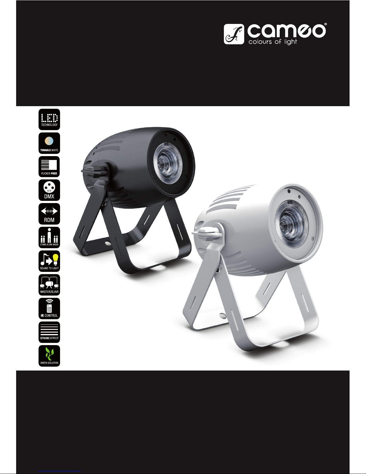
Q SPOT 40 TUNABLE WHITE
COMPACT 40W LED SPOT
BLACK HOUSING WHITE HOUSING
CLQS40TW CLQS40TWWH
USER´S MANUAL
BEDIENUNGSANLEITUNG
MANUEL D`UTILISATION
MANUAL DE USUARIO
INSTRUKCJA OBSŁUGI
MANUALE D‘ USO

CONTENTS / INHALTSVERZEICHNIS / CONTENU / CONTENIDO / TREŚĆ / CONTENUTO
ENGLISH
PREVENTIVE MEASURES 3-4
INTRODUCTION 4
CONNECTIONS, OPERATING AND DISPLAY ELEMENTS 5
OPERATION 6-9
INFRARED REMOTE CONTROL (OPTIONAL) 10-11
DIFFUSERS 11
INSTALLATION 11
DMX TECHNOLOGY 12
TECHNICAL DATA 13
MANUFACTURER’S DECLARATIONS 13-14
DMX CONTROL 75-76
DEUTSCH
SICHERHEITSHINWEISE 15-16
EINFÜHRUNG 16
ANSCHLÜSSE, BEDIEN- UND ANZEIGEELEMENTE 17-18
BEDIENUNG 18-21
INFRAROT FERNBEDIENUNG (OPTIONAL) 22-23
STREUSCHEIBEN 23
AUFSTELLUNG UND MONTAGE 23
DMX TECHNIK 24
TECHNISCHE DATEN 25
HERSTELLERERKLÄRUNGEN 25-26
DMX STEUERUNG 75-76
FRANCAIS
MESURES PRÉVENTIVES 27-28
INTRODUCTION 28
RACCORDEMENTS, ÉLÉMENTS DE COMMANDE ET
D’AFFICHAGE 29
MODE D’EMPLOI 30-33
TÉLÉCOMMANDE INFRAROUGE (EN OPTION) 34-35
DIFFUSEURS 35
INSTALLATION ET MONTAGE 35
TECHNOLOGIE DMX 36
CARACTÉRISTIQUES TECHNIQUES 37
DÉCLARATIONS DU FABRICANT 38
PILOTAGE EN MODE DMX 75-76
ESPAÑOL
MEDIDAS DE SEGURIDAD 39-40
INTRODUCCIÓN 40
CONEXIONES, MANDOS Y ELEMENTOS DE VISUALIZACIÓN 41-42
FUNCIONAMIENTO 42-45
MANDO A DISTANCIA POR INFRARROJOS (OPCIONAL) 46-47
DIFUSORES 47
INSTALACIÓN Y MONTAJE 47
TECNOLOGÍA DMX 48
DATOS TÉCNICOS 49
DECLARACIONES DEL FABRICANTE 49-50
CONTROL DMX 75-76
POLSKI
ŚRODKI OSTROŻNOŚCI 51-52
WPROWADZENIE 52-53
PRZYŁĄCZA, ELEMENTY OBSŁUGOWE I WSKAŹNIKI 53-54
OBSŁUGA 54-57
PILOT ZDALNEGO STEROWANIA NA PODCZERWIEŃ
(OPCJONALNY) 58-59
DYFUZORY 59
USTAWIANIE I MONTAŻ 59
TECHNIKA DMX 60
DANE TECHNICZNE 61
OŚWIADCZENIA PRODUCENTA 61-62
STEROWANIE DMX 75-76
ITALIANO
MISURE PRECAUZIONALI 63-64
INTRODUZIONE 64
RACCORDI, ELEMENTI DI COMANDO E DI VISUALIZZAZIONE 65-66
COMANDO 66-69
TELECOMANDO A INFRAROSSI (OPZIONALE) 70-71
DIFFUSORI 71
INSTALLAZIONE E MONTAGGIO 71
TECNOLOGIA DMX 72
DATI TECNICI 73
DICHIARAZIONI DEL PRODUTTORE 73-74
CONTROLLO DMX 75-76

ENGLISH
YOU‘VE MADE THE RIGHT CHOICE!
We have designed this product to operate reliably over many years. Please read this User‘s Manual carefully, so that you can begin making
optimum use of your Cameo Light product quickly. Learn more about Cameo Light on our website WWW.CAMEOLIGHT.COM.
PREVENTIVE MEASURES
1. Please read these instructions carefully.
2. Keep all information and instructions in a safe place.
3. Follow the instructions.
4. Observe all safety warnings. Never remove safety warnings or other information from the equipment.
5. Use the equipment only in the intended manner and for the intended purpose.
6. Use only sufficiently stable and compatible stands and/or mounts (for fixed installations). Make certain that wall mounts are properly installed and
secured. Make certain that the equipment is installed securely and cannot fall down.
7. During installation, observ e the applicable safety regulations for your country.
8. Never install and operate the equipment near radiators, heat registers, ovens or other sources of heat. Make certain that the equipment is
always installed so that is cooled sufficiently and cannot overheat.
9. Never place sources of ignition, e.g., burning candles, on the equipment.
10. Ventilation slits must not be blocked.
11. This appliance is designed exclusively for indoor use, do not use this equipment in the immediate vicinity of water (does not apply
to special outdoor equipment - in this case, observe the special instructions noted below). Do not expose this equipment to flammable
materials, fluids or gases.
12. Make certain that dripping or splashed water cannot enter the equipment. Do not place containers filled with liquids, such as vases or
drinking vessels, on the equipment.
13. Make certain that objects cannot fall into the device.
14. Use this equipment only with the accessories recommended and intended by the manufacturer.
15. Do not open or modify this equipment.
16. After connecting the equipment, check all cables in order to prevent damage or accidents, e.g., due to tripping hazards.
17. During transport, make certain that the equipment cannot fall down and possibly cause property damage and personal injuries.
18. If your equipment is no longer functioning properly, if fluids or objects have gotten inside the equipment or if it has been damaged in
anot her way, switch it off immediately and unplug it from the mains outlet (if it is a powered device). This equipment may only be repaired
by authorized, qualified personnel.
19. Clean the equipment using a dry cloth.
20. Comply with all applicable disposal laws in your country. During disposal of packaging, please separate plastic and paper/cardboard.
21. Plastic bags must be kept out of reach of children.
FOR EQUIPMENT THAT CONNECTS TO THE POWER MAINS:
22. CAUTION: If the power cord of the device is equipped with an earthing contact, then it must be connected to an outlet with a protective
ground. Never deactivate the protective ground of a power cord.
23. If the equipment has been exposed to strong fluctuations in temperature (for example, after transport), do not switch it on immediately.
Moisture and condensation could damage the equipment. Do not switch on the equipment until it has reached room temperature.
24. Before connecting the equipment to the power outlet, first verify that the mains voltage and frequency match the values specified on the
equipment. If the equipment has a voltage selection switch, connect the equipment to the power outlet only if the equipment values and the
mains power values match. If the included power cord or power adapter does not fit in your wall outlet, contact your electrician.
25. Do not step on the power cord. Make certain that the power cable does not become kinked, especially at the mains outlet and/or power
adapter and the equipment connector.
26. When connecting the equipment, make certain that the power cord or power adapter is always freely accessible. Always disconnect the
equipment from the power supply if the equipment is not in use or if you want to clean the equipment. Always unplug the power cord and
power adapter from the power outlet at the plug or adapter and not by pulling on the cord. Never touch the power cord and power adapter
with wet hands.
27. Whenever possible, avoid switching the equipment on and off in quick succession because otherwise this can shorten the useful life of
the equipment.
28. IMPORTANT INFORMATION: Replace fuses only with fuses of the same type and rating. If a fuse blows repeatedly, please contact an
authorised service centre.
29. To disconnect the equipment from the power mains completely, unplug the power cord or power adapter from the power outlet.
30. If your device is equipped with a Volex power connector, the mating Volex equipment connector must be unlocked before it can be removed. However, this also means that the equipment can slide and fall down if the power cable is pulled, which can lead to personal injuries
and/or other damage. For this reason, always be careful when laying cables.
31. Unplug the power cord and power adapter from the power outlet if there is a risk of a lightning strike or before extended periods of disuse.
32. The device must only be installed in a voltage-free condition (disconnect the mains plug from the mains).
33. Dust and other debris inside the unit may cause damage. The unit should be regularly serviced or cleaned (no guarantee) depending on
ambient conditions (dust etc., nicotine, fog) by qualified personnel to prevent overheating and malfunction.
34. Please keep a distance of at least 0.5 m to any combustible materials.
35. Power cables to power multiple devices must have a cross-section of at least 1.5 mm². Within the EU, the cables must correspond to
H05VV-F, or similar. Suitable cables are offered by Adam Hall. With these cables, you can connect multiple devices via the power OUT connection to the power IN connection of an additional device. Make sure that the total current consumption of all connected devices does not
exceed the specified value on all connected devices (label on the device). Make sure to keep power cable connections as short as possible.

INTRODUCTION
COMPACT 40W LED SPOT TUNABLE WHITE
CLQS40TW (black housing)
CLQS40TWWH (white housing)
CONTROL FUNCTIONS
1-channel, 2-channel, 3-channel 1, 3-channel 2, 7-channel DMX control
Master/Slave operation
Standalone operation
Control via IR remote control IR remote control (optional)
FEATURES
Compact spot with 40W dual LED (cool white/warm white). DMX-512 control. Master/Slave operation. Music-control. Control via IR remote
control IR remote control (optional). Fast Access Feature. Retaining lug and mounting bracket. 2 diffusers for different beam angles. Housing
colour black or white. Operating voltage 100-240 V AC/50-60Hz. Power consumption 55W.
The spotlights feature the RDM standard (remote device management). Remote device management allows the user to view status and
configuration of RDM terminals via an RDM-capable controller.
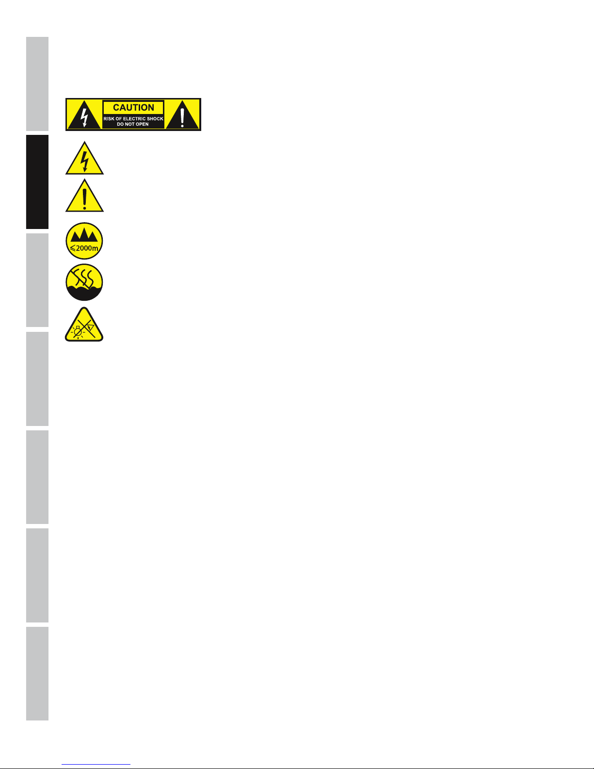
CAUTION:
To reduce the risk of electric shock, do not remove cover (or back). There are no user serviceable parts
inside. Maintenance and repairs should be exclusively carried out by qualified service personnel.
The warning triangle with lightning symbol indicates dangerous uninsulated voltage inside the unit, which may cause an
electrical shock.
The warning triangle with exclamation mark indicates important operating and maintenance instructions.
Warning! This device is designed for use below 2000 metres in altitude.
Warning! This product is not intended for use in tropical climates.
Caution! Intense LED light source! Risk of eye damage. Do not look into the light source.
CAUTION! IMPORTANT INFORMATION ABOUT LIGHTING PRODUCTS!
1. The product has been developed for professional use in the field of event technology and is not suitable as household lighting.
2. Do not stare, even temporarily, directly into the light beam.
3. Do not look at the beam directly with optical instruments such as magnifiers.
4. Stroboscope effects may cause epileptic seizures in sensitive people! People with epilepsy should definitely avoid places where
strobes are used.
5
DMX
DEUTSCHFRANCAIS
ESPAÑOL
ENGLISH
ITALIANO POLSKI
4 5
8
1
3
2
6
7
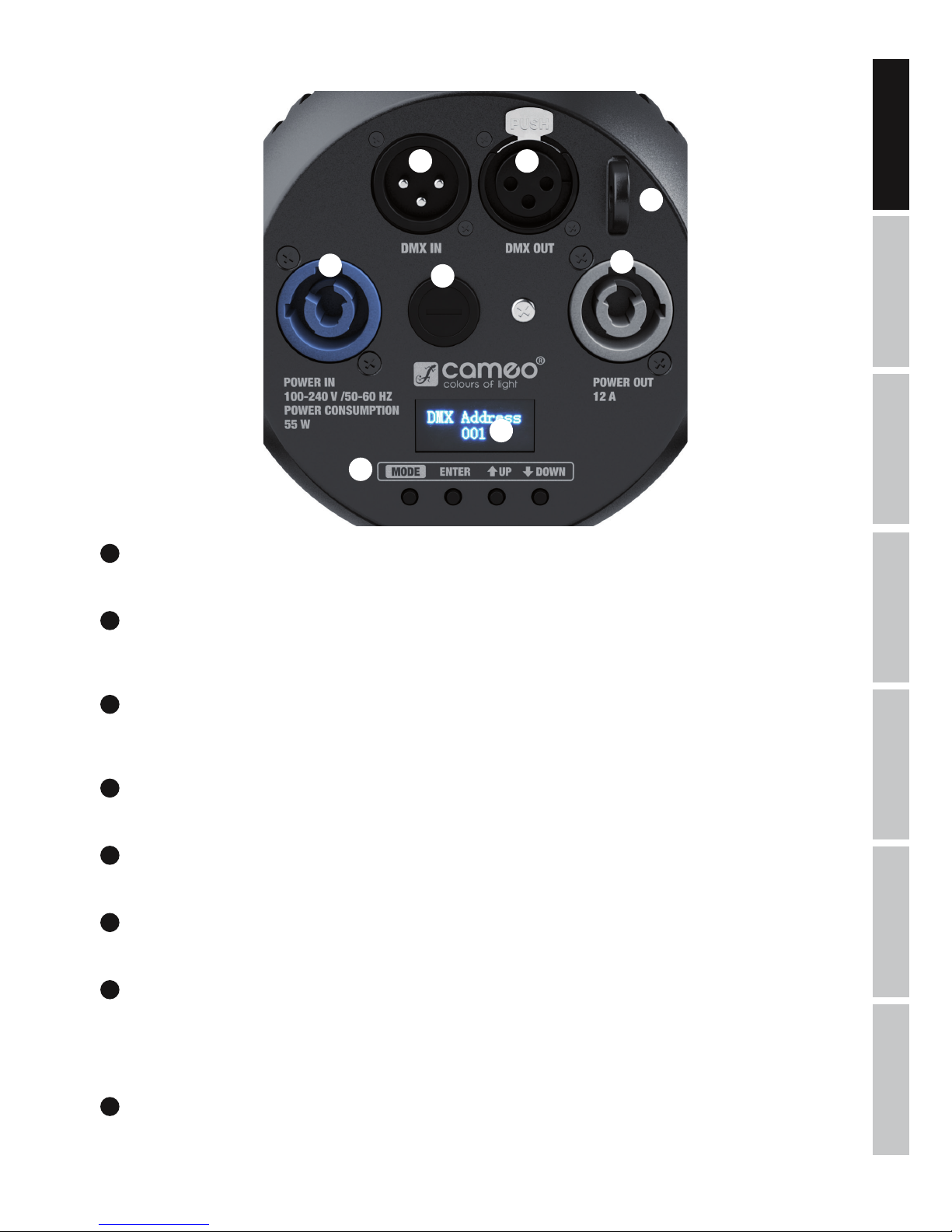
CONNECTIONS, OPERATING AND DISPLAY ELEMENTS
1
POWER IN
Blue power input socket for power supply to the device. A suitable power cable is included.
2
POWER OUT
White power output socket for the power supply of additional CAMEO spotlights. Ensure that the total current consumption of all connected
devices does not exceed the value specified on the device in amperes (A).
3
FUSE
Fuse holder. Fuse T1A/250 V (5 x 20 mm). IMPORTANT: Replace the fuse only with a fuse of the same type and value. In the event of repeated
fuse failure, please contact an authorised service centre.
4
DMX IN
Male 3-pin XLR socket for connection to a DMX control device (e.g. DMX console).
5
DMX OUT
Female 3-pin XLR socket for sending the DMX control signal.
6
OLED DISPLAY
The OLED display shows the operating mode and other system information.
7
CONTROL BUTTONS
MODE – press MODE to access the selection menu for system settings. Press repeatedly to go back to the main display. ENTER – press ENTER
to access the menu levels to make value changes, and to access the sub-menus. Confirm value changes by pressing ENTER. UP and DOWN –
select individual menu items in the selection menu (DMX address, operating mode etc.) and in the sub-menus. Allow changes to the value of a
menu item, such as the DMX address as required.
8
EYELET FOR SECURING CABLE
Overhead installation must only be carried out by qualified personnel. A suitable safety cable must be fitted to the floodlight’s eyelet to
ensure that it does not fall down.
6
DMX
ITALIANO
POLSKI
ESPAÑOL
FRANCAIS
DEUTSCHENGLISH
OPERATION
PLEASE NOTE
• As soon as the spotlight is correctly is connected to the power supply, the following will be displayed in succession: "Software Update
Please Wait..." (only for service purposes), "Welcome to Cameo", the model name and the software version. After this process, the lamp is
ready for operation and starts in the previously selected mode.
• If the DMX operating mode is activated and there is no DMX signal at the DMX input, the display will start to flash after a few seconds.
• After approximately 30 seconds of inactivity, the display will automatically show the currently active operating mode.
• Fast Access Feature: In order to simplify the menu guide, the device has an intelligent menu structure that allows direct access to previously
selected menu items and sub-menu items. 1. Press MODE and ENTER simultaneously for direct access to the last-edited sub-menu item, where
you can make changes instantly as required (DMX starting address and all modes). 2. Press MODE for direct access to the last-selected and
last-edited menu item. Press ENTER to access the last-selected and last-edited sub-menu item (DMX starting address and all modes).
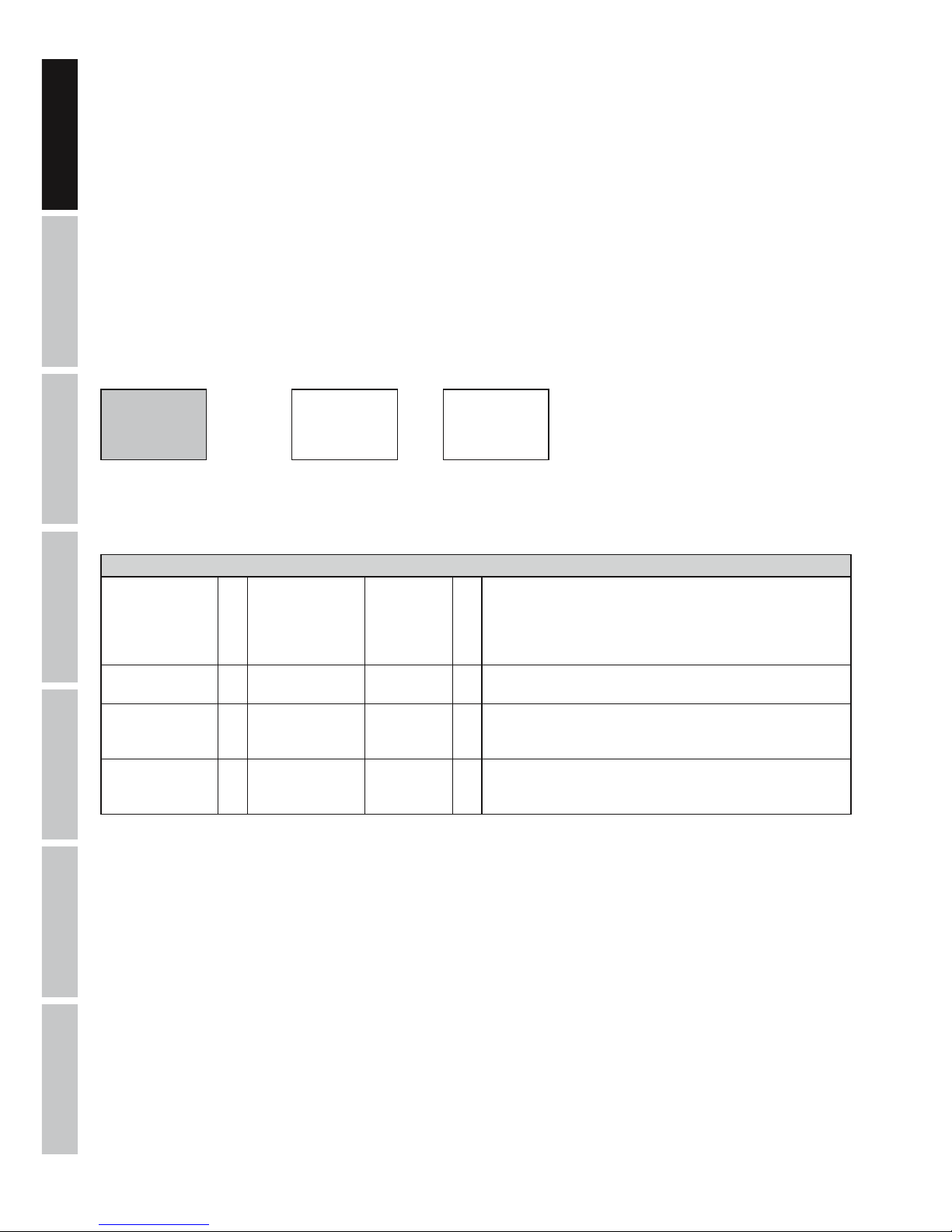
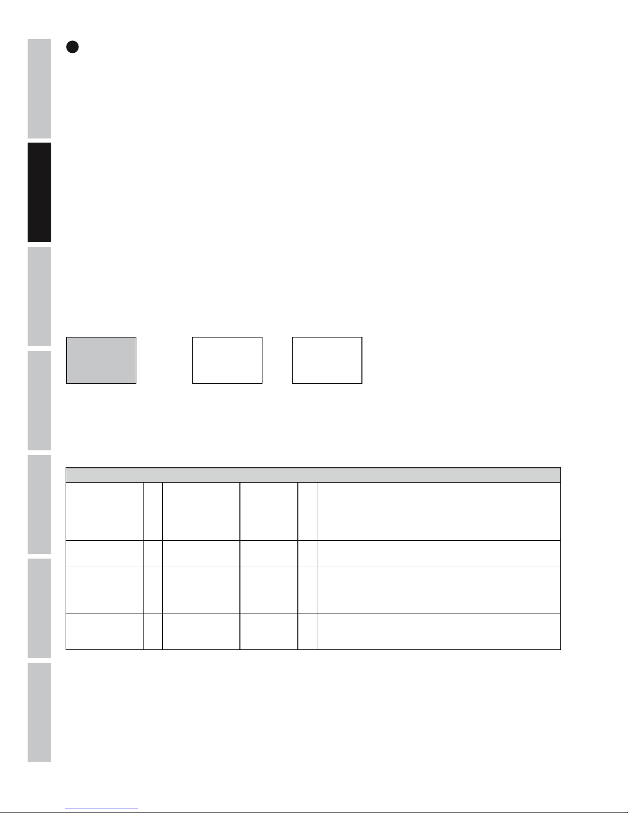
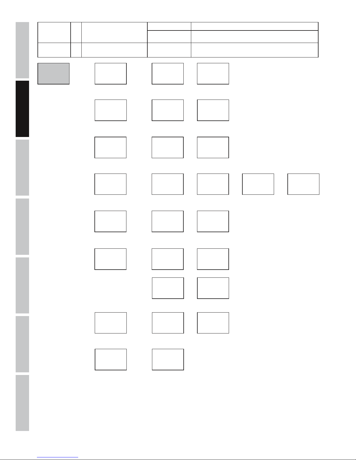
CONFIGURING DMX START ADDRESS
Press the MODE button repeatedly until "Menu DMX Address” or “Menu Mode” appears in the display. If necessary, select the menu item
"Menu DMX address" by using the buttons UP and DOWN and press ENTER. Using the UP and DOWN buttons, select the desired DMX start
address and press ENTER to confirm. The DMX mode will start simultaneously.
Menu
DMX Address
DMX Address
001
DMX Address
512
ENTER
UP/DOWN
- ENTER
SETTING OPERATING MODE (Mode)
Press the MODE button repeatedly until "Menu Mode” or “Menu DMX Address” appears in the display. If necessary, select the menu item "Menu
Mode" by using the buttons UP and DOWN and then press ENTER. Now select the desired operating mode with the buttons UP and DOWN and
confirm with ENTER (see tables, note submenus). Comprehensive DMX tables can be found in these instructions under “DMX CONTROL”.
Operating Modes
Mode DMX = DMX operating
mode
01CH
02CH
03CH1
03CH2
07CH
= 1-channel mode
2-channel mode
3-channel 1 mode
3-channel 2 mode
7-channel mode
Mode Sound = sound control
mode
Sound = spotlight reacts to bass impulses. Adjustable microphone
sensitivity.
Mode Slave = slave mode Slave = connect DMX IN on the slave unit to DMX OUT on the master unit
(same model) and enable one of the standalone modes on the
master unit. Now the slave unit will follow the master unit.
Mode Static = setting a "scene"
without an external
controller
Static = Dimmer and CT (Colour Temperature) can be configured individ-
ually.
7
DMX
DEUTSCHFRANCAIS
ESPAÑOL
ENGLISH
ITALIANO POLSKI
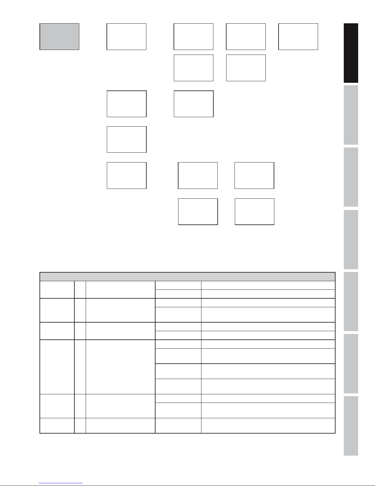
SYSTEM SETTINGS (settings)
To access system settings, press the MODE button repeatedly until "Menu DMX Addr” or “Menu Mode” appears in the display. Now select
the menu item "Menu Settings" using the UP and DOWN keys and press ENTER. Now select the desired submenu item, but this time with
the buttons UP and DOWN and confirm with ENTER (see tables, note submenus).
Menu
Mode
DMX mode
01CH
ENTER
UP/DOWN
ENTER
UP/DOWN
Mode
DMX
DMX mode
02CH
DMX mode
03CH1
/ /
ENTER
DMX mode
03CH2
DMX mode
07CH
/
-
Mode
Static
Static
Dimmer
Static
CT
ENTER
UP/DOWN
ENTER - UP/DOWN
ENTER - UP/DOWN
Dimmer
000-255
ENTER
CT
000-255
(cool-warm)
ENTER
ENTER
Mode
Slave
/
ENTER
UP/DOWN
Mic Sens
00-99
ENTER
Mode
Sound
/
/
/
Settings
Display Rev = rotate display by 180° Display Rev On = rotate display by 180° (e.g. for overhead installation)
Display Rev On = normal orientation of the display
Display = automatic display shutdown Display On = permanently on
Display Off = automatic display shutdown after approximately 1 minute
of inactivity
DMXFail = operating status with DMX
signal fault
Hold = last command is retained
Blackout = activates blackout
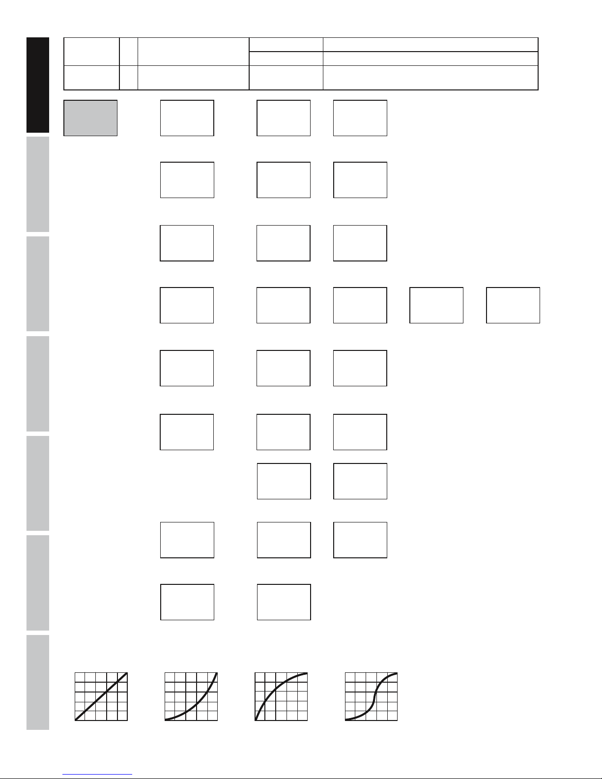
Dim.Curve = dimmer curve Linear = light intensity increases linearly with DMX value
Exp = light intensity can be finely adjusted at lower DMX values
and broadly adjusted at higher DMX values
Log = light intensity can be broadly adjusted at lower DMX values
and finely adjusted at higher DMX values
S-Curve = light intensity can be finely adjusted at lower and higher
DMX values and broadly adjusted at medium DMX values
Dimmer Resp. = dimmer sensitivity LED = spotlight responds abruptly to changes in DMX value
Halogen = spotlight behaves like a halogen spotlight with soft
brightness changes
White Balance = white balance cool white
warm white
= individual white balance. Cross-mode configuration of the
2 cool white and warm white LEDs
8
DMX
ITALIANO
POLSKI
ESPAÑOL
FRANCAIS
DEUTSCHENGLISH
IR Remote = activate or deactivate control
by IR remote control
On = IR remote control activated
Off = IR remote control deactivated
Factory Reset = reset to factory settings Reset Now? ENTER = reset to factory setting
MODE = do not perform reset
Menu
Settings
Settings
Display Rev
Display Rev
On
Display Rev
Off
ENTER
UP/DOWN
ENTER
UP/DOWN
/
/
ENTER
ENTER
Settings
Display
Display
On
Display
Off
ENTER
UP/DOWN
/
ENTER ENTER
/
Settings
Dim. Curve
Dim. Curve
Linear
Dim. Curve
Exp
Dim. Curve
Log
Dim. Curve
S-Curve
ENTER
UP/DOWN
/ / /
ENTER
ENTER
ENTER ENTER
/
Settings
Dimmer Resp.
Dimmer Resp.
LED
Dimmer Resp.
Halogen
ENTER
UP/DOWN
/
/
ENTER
ENTER
Settings
White Balance
White Balance
CW
White Balance
WW
ENTER
UP/DOWN
/
/
ENTER
ENTER
Settings
Factory Reset
Reset Now?
ENTER
Yes = ENTER
No = MODE
Settings
DMX Fail
DMX Fail
Hold
DMX Fail
Blackout
ENTER
UP/DOWN
/
/
ENTER
ENTER
CW
000-255
WW
000-255
UP/DOWN - ENTER
UP/DOWN - ENTER
Settings
IR Remote
IR Remote
On
IR Remote
Off
ENTER
UP/DOWN
/
/
ENTER
ENTER
linear
DMX value
Light intensity
exponential
DMX value
Light intensity
logarithmic
DMX value
Light intensity
S-curve
DMX value
Light intensity
Dimmer curves

9
DMX
DEUTSCHFRANCAIS
ESPAÑOL
ENGLISH
ITALIANO POLSKI
SYSTEM INFORMATION (System Info)
To read a variety of system information, press the MODE button repeatedly until "Menu DMX Addr” or “Menu Mode” appears in the display.
Select the menu item "Menu System Info" using the UP and DOWN keys and press ENTER. Use the UP and DOWN controls to select the
desired sub-menu item, and press ENTER to display the corresponding information.
System Info
Firmware = display software
version
V1.xx Press ENTER to display information
Temperature = display LED
temperature in
degrees Celsius or
Fahrenheit
Temperature LED = display temperature by pressing ENTER
Temperature
C/F
= select temperature unit to degrees Celsius or degrees Fahrenheit. Confirm with ENTER
Op.Hours = display operating
time in hours
xxxxh Press ENTER to display information
Menu
System Info
System Info
Firmware
Software version
V1.xx
ENTER
UP/DOWN
ENTER
/
System Info
Temperature
ENTER
UP/DOWN
Temperature
LED
Temperature
C/F
/
ENTER ENTER - UP/DOWN
Temperature
xxxC/F
Unit
C
Unit
F
/
ENTER ENTER
System Info
Op. hours
Op. hours
xxxh
ENTER
/

10
DMX
ITALIANO
POLSKI
ESPAÑOL
FRANCAIS
DEUTSCHENGLISH
INFRARED REMOTE CONTROL (optional)
Activate the infrared remote control in system settings (Menu Settings) under “IR remote” (IR Remote On). Aim the infrared remote control directly at the infrared sensor built into the front of the spotlight. The maximum range is approximately 8 metres.
BL/ON/OFF (Blackout)
The BL button is used to switch off the LED in the spotlight, regardless of operating mode. Press the BL button again to reactivate the
previously selected mode.
SP/SPEED
Without function.
/ BRIGHTNESS
12 brightness settings. Press the button
then select the desired brightness using the + and - buttons (level 1= blackout).
FL/FLASH (Strobe)
Activate the strobe effect and set one of its 14 speeds. Press the FL button, then use the + and - buttons to select the flash frequency (level
1 = strobe disabled, level 2 = slowest flash frequency, level 14 = fastest flash frequency).
CW/WW (R, G, B, W, A and UV without function)
Press the button CW (cool white) or WW (warm white) then adjust the brightness of the corresponding LED to the desired level (of 12 levels)
by repeatedly pressing the + or - buttons. The LEDS are switched off at level 1.
PG
Without function.
CM
Without function.

11
DMX
DEUTSCHFRANCAIS
ESPAÑOL
ENGLISH
ITALIANO POLSKI
SC (sound-controlled strobe)
To activate the sound control mode, press SC and set the microphone sensitivity between 1 and 11 using the + and - buttons as required
(11 levels).
AU
Without function.
A
DIFFUSERS
Two diffusers are supplied with the lamp, each with a different beam angle (1 x 10° and 1 x 25°). The beam angle of the lamp can be set at
4.5° (without diffuser), 10°, or 25°. Insert the desired diffuser in front of the light-emitting lens and secure it with the supplied securing ring.
INSTALLATION
Thanks to its integrated double bracket, the lamp can be positioned in a suitable location on a level surface. Installation on a traverse is possible
with a suitable traverse clamp (not supplied). Ensure firm connection to the mounting bracket and secure the lamp to the the securing lug (A) with a
suitable safety cable.
Important: Overhead mounting requires extensive experience, including the calculation of the load limit values of the installation material and
regular safety inspection of all installation materials and devices, such as lights and speakers. If you do not have these qualifications, do not attempt
to perform an installation yourself. Refer instead to a qualified professional.
12
DMX
ITALIANO
POLSKI
ESPAÑOL
FRANCAIS
DEUTSCHENGLISH
DMX TECHNOLOGY
DMX-512
DMX (Digital Multiplex) is the designation for a universal transmission protocol for
communications between corresponding devices and controllers. A DMX controller sends
DMX data to the connected DMX device(s). The DMX data is always transmitted as a serial
data stream that is forwarded from one connected device to the next via the "DMX IN" and
"DMX OUT" connectors (XLR plug-type connectors) that are found on every DMX-capable
device, provided the maximum number of devices does not exceed 32 units. The last device
in the chain needs to be equipped with a terminator (terminating resistor).
DMX CONNECTION
DMX is the common "language" via which a very wide range of types and models of equipment from various manufacturers can
be connected with one another and controlled via a central controller, provided that all of the devices and the controller are DMX
compatible. For optimum data transmission, it is necessary to keep the connecting cables between the individual devices as short as
possible. The order in which the devices are integrated in the DMX network has no influence on the addresses. Thus the device with
the DMX address 1 can be located at any position in the (serial) DMX chain: at the beginning, at the end or somewhere in the middle.
If the DMX address 1 is assigned to a device, the controller "knows" that it should send all data allocated to address 1 to this device
regardless of its position in the DMX network.
SERIAL CONNECTION OF MULTIPLE LIGHTS
1. Connect the male XLR connector (3-pin or 5-pin) of the DMX cable to the DMX output (female XLR socket) of the first DMX device
(e.g. DMX-Controller).
2. Connect the female 3-pin XLR connector of the DMX cable connected to the first projector to the DMX input (male 3-pin socket)
of the next DMX device. In the same way, connect the DMX output of this device to the DMX input of the next device and repeat until
all devices have been connected. Please note that as a rule, DMX devices are connected in series and connections cannot be shared
without active splitters. The maximum number of DMX devices in a DMX chain should not exceed 32 units.
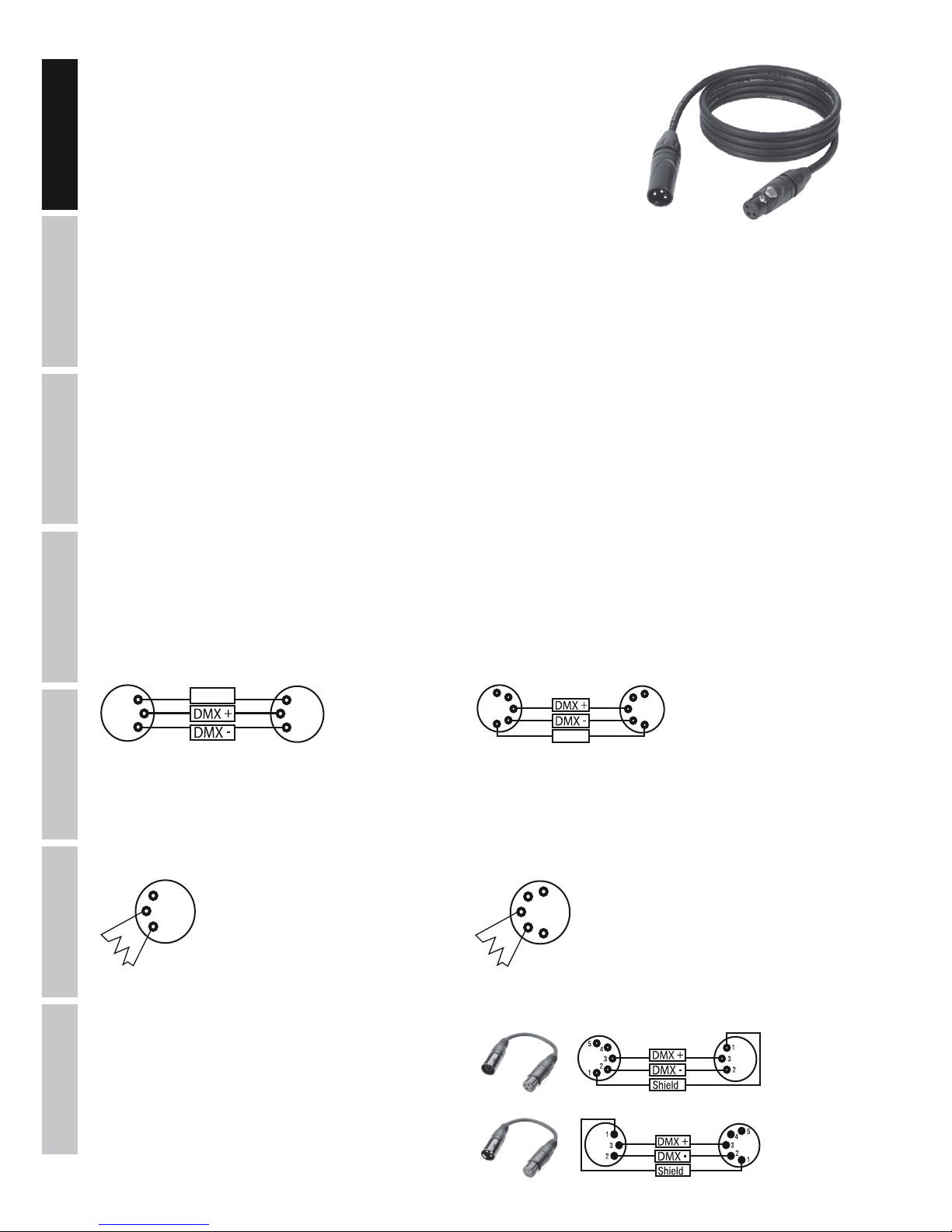
The Adam Hall 3 STAR, 4 STAR, and 5 STAR product ranges include an extensive selection of suitable cables.
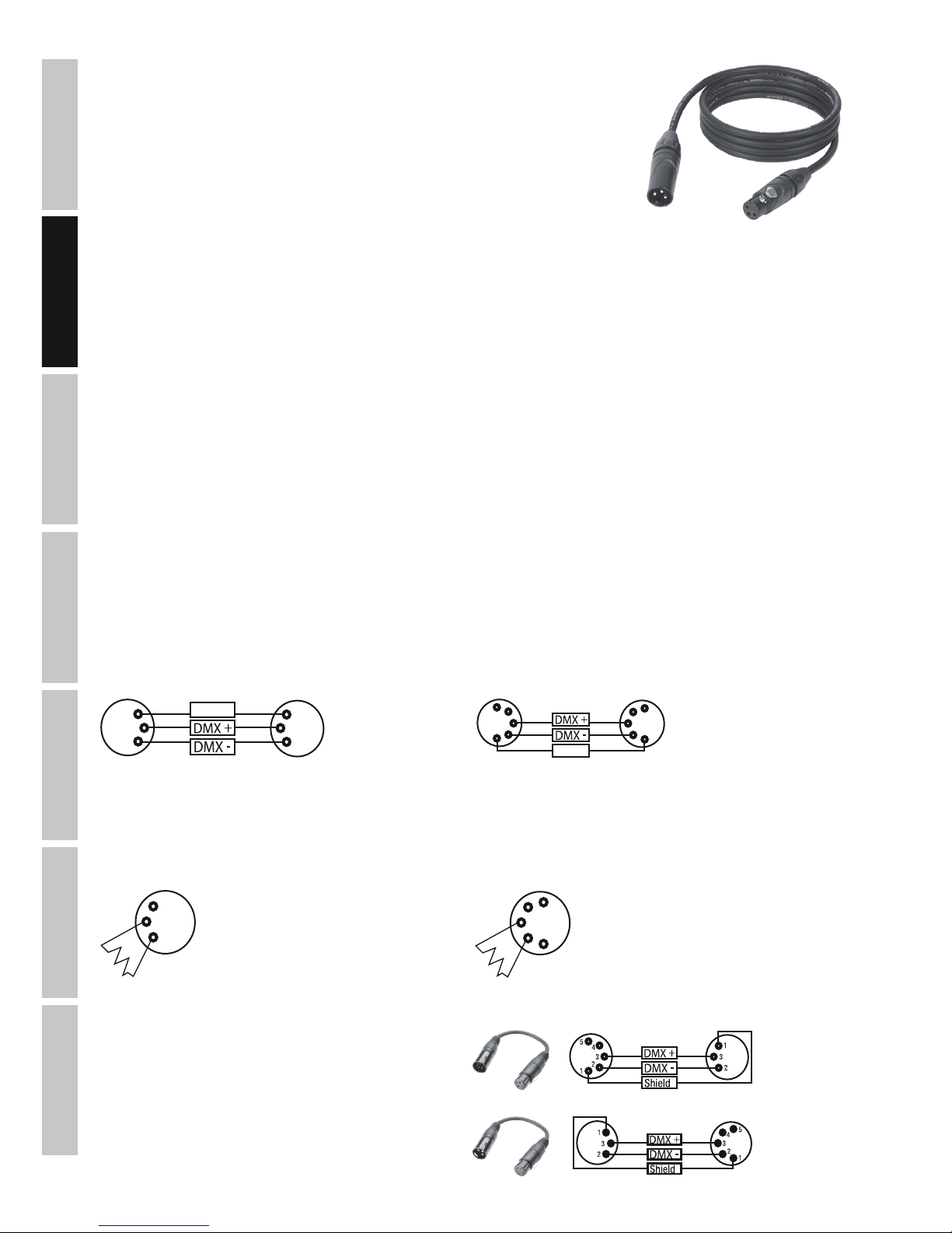
DMX CABLES
When fabricating your own cables, always observe the illustrations on this page. Never connect the shielding of the cable to the ground
contact of the plug, and always make certain that the shielding does not come into contact with the housing of the XLR plug. If the shielding
is connected to the ground, this can lead to short-circuiting and system malfunctions.
Pin Assignment
DMX cable with 3-pin XLR connectors: DMX cable with 5-pin XLR connectors (pin 4 and 5 are not used):
Shield
2
3
1
2
3
1
1
2
3
4
5
1
2
3
4
5
Shield
DMX TERMINATORS (TERMINATING RESISTORS)
To prevent system errors, the last device in a DMX chain needs to be equipped with a terminating resistor (120 ohm, 1/4 Watt).
3-pin XLR connector with a terminating resistor: K3DMXT3
5-pin XLR connector with a terminating resistor: K3DMXT5
Pin Assignment
3-pin XLR connector: 5-pin XLR connector:
2
3
1
1
2
3
4
5
DMX ADAPTER
The combination of DMX devices with 3-pin connectors and DMX devices with 5-pin connectors in a DMX chain is possible with suitable
adapters.
Pin Assignment
DMX Adapter 5-pin XLR male to 3-pin XLR female: K3DGF0020
Pins 4 and 5 are not used.
Pin Assignment
DMX Adapter 3-pin XLR male to 5-pin XLR female: K3DHM0020
Pins 4 and 5 are not used.

13
DMX
DEUTSCHFRANCAIS
ESPAÑOL
ENGLISH
ITALIANO POLSKI
TECHNICAL DATA
Model name: CLQS40TW(WH)
Product type: LED spotlight
Type: Compact spotlight
Colour spectrum LED: cool white/warm white
Number of LEDs: 1
LED type: Dual LED 40W
LED colour temperature: 3200-6800 K
PWM frequency: 3600 Hz
Beam angle: 4.5° (10°, 25° with diffuser)
DMX input: 3-pin male XLR
DMX output: 3-pin female XLR
DMX mode: 1-channel, 2-channel, 3-channel 1, 3-channel 2, 7-channel
DMX functions: dimmer, cool white, warm white, strobe, colour temperature, dimmer response, dimmer curves
Standalone functions: master/slave operation, stroboscope, dimmer response, dimmer curves, static mode,
music-control
Control: DMX512, IR remote control, RDM-enabled
Operating controls: mode, enter, up, down
Display elements: OLED display
Operating voltage: 100 –240 V AC/50–60Hz
Power consumption: 55W
Light intensity (@ 1m): 95000 lx (4,5°)
Lighting power: 1431 lm
Power connection: blue power input socket
white power output socket (max. 12A)
Fuse: T1A (5 x 20 mm)
Ambient temperature (in operation): 0-40°C
Relative air humidity: <85%, non-condensing
Housing material: Metal
Housing colour: black (CLQS40TW)
white (CLQS40TWWH)
Housing cooling: convection
Dimensions (W x H x D, without
bracket):
220 x 230 x 220mm
Weight: 2.2kg
Additional features: Adjustable mounting bracket or stand included, securing lug, power cable and 2 diffusers includ-
ed, IR remote control optional
MANUFACTURER´S DECLARATIONS
MANUFACTURER‘S WARRANTY & LIMITATIONS OF LIABILITY
You can find our current warranty conditions and limitations of liability at: https://cdn-shop.adamhall.com/media/pdf/Manufacturers-Declarations-CAMEO_DE_EN_ES_FR.pdf. To request warranty service for a product, please contact Adam Hall GmbH, Adam-Hall-Str. 1,
61267 Neu Anspach / Email: Info@adamhall.com / +49 (0)6081 / 9419-0.
CORRECT DISPOSAL OF THIS PRODUCT
(valid in the European Union and other European countries with a differentiated waste collection system)
This symbol on the product, or on its documents indicates that the device may not be treated as household waste. This is to avoid
environmental damage or personal injury due to uncontrolled waste disposal. Please dispose of this product separately from other waste
and have it recycled to promote sustainable economic activity. Household users should contact either the retailer where they purchased
this product, or their local government office, for details on where and how they can recycle this item in an environmentally friendly manner.
Business users should contact their supplier and check the terms and conditions of the purchase contract. This product should not be mixed
with other commercial waste for disposal.

14
DMX
ITALIANO
POLSKI
ESPAÑOL
FRANCAIS
DEUTSCHENGLISH
FCC STATEMENT
This device complies with Part 15 of the FCC Rules. Operation is subject to the following two conditions:
(1) This device may not cause harmful interference, and
(2) This device must accept any interference received, including interference that may cause undesired operation
CE Compliance
Adam Hall GmbH states that this product meets the following guidelines (where applicable):
R&TTE (1999/5/EC) or RED (2014/53/EU) from June 2017
Low voltage directive (2014/35/EU)
EMV directive (2014/30/EU)
RoHS (2011/65/EU)
The complete declaration of conformity can be found at www.adamhall.com.
Furthermore, you may also direct your enquiry to info@adamhall.com.

15
DMX
DEUTSCHFRANCAIS
ESPAÑOL
ENGLISH
ITALIANO POLSKI
DEUTSCH
SIE HABEN DIE RICHTIGE WAHL GETROFFEN!
Dieses Gerät wurde unter hohen Qualitätsanforderungen entwickelt und gefertigt, um viele Jahre einen reibungslosen Betrieb zu gewährleisten. Bitte lesen Sie diese Bedienungsanleitung sorgfältig, damit Sie Ihr neues Produkt von Cameo Light schnell und optimal einsetzen
können. Weitere Informationen über Cameo Light erhalten Sie auf unserer Website WWW.CAMEOLIGHT.COM.
SICHERHEITSHINWEISE
1. Lesen Sie diese Anleitung bitte sorgfältig durch.
2. Bewahren Sie alle Informationen und Anleitungen an einem sicheren Ort auf.
3. Befolgen Sie die Anweisungen.
4. Beachten Sie alle Warnhinweise. Entfernen Sie keine Sicherheitshinweise oder andere Informationen vom Gerät.
5. Verwenden Sie das Gerät nur in der vorgesehenen Art und Weise.
6. Verwenden Sie ausschließlich stabile und passende Stative bzw. Befestigungen (bei Festinstallationen). Stellen Sie sicher, dass Wandhalterungen
ordnungsgemäß installiert und gesichert sind. Stellen Sie sicher, dass das Gerät sicher installiert ist und nicht herunterfallen kann.
7. Beachten Sie bei der Installation die für Ihr Land geltenden Sicherheitsvorschriften.
8. Installieren und betreiben Sie das Gerät nicht in der Nähe von Heizkörpern, Wärmespeichern, Öfen oder sonstigen Wärmequellen. Sorgen
Sie dafür, dass das Gerät immer so installiert ist, dass es ausreichend gekühlt wird und nicht überhitzen kann.
9. Platzieren Sie keine Zündquellen wie z.B. brennende Kerzen auf dem Gerät.
10. Lüftungsschlitze dürfen nicht blockiert werden.
11. Das Gerät wurde ausschließlich für die Verwendung in Innenräumen entwickelt, betreiben Sie das Gerät nicht in unmittelbarer Nähe von
Wasser (gilt nicht für spezielle Outdoor Geräte - beachten Sie in diesem Fall bitte die im Folgenden vermerkten Sonderhinweise). Bringen Sie
das Gerät nicht mit brennbaren Materialien, Flüssigkeiten oder Gasen in Berührung.
12. Sorgen Sie dafür, dass kein Tropf- oder Spritzwasser in das Gerät eindringen kann. Stellen Sie keine mit Flüssigkeit gefüllten Behältnisse
wie Vasen oder Trinkgefäße auf das Gerät.
13. Sorgen Sie dafür, dass keine Gegenstände in das Gerät fallen können.
14. Betreiben Sie das Gerät nur mit dem vom Hersteller empfohlenen und vorgesehenen Zubehör.
15. Öffnen Sie das Gerät nicht und verändern Sie es nicht.
16. Überprüfen Sie nach dem Anschluss des Geräts alle Kabelwege, um Schäden oder Unfälle, z. B. durch Stolperfallen zu vermeiden.
17. Achten Sie beim Transport darauf, dass das Gerät nicht herunterfallen und dabei möglicherweise Sach- und Personenschäden verursachen kann.
18. Wenn Ihr Gerät nicht mehr ordnungsgemäß funktioniert, Flüssigkeiten oder Gegenstände in das Geräteinnere gelangt sind, oder das Gerät
anderweitig beschädigt wurde, schalten Sie es sofort aus und trennen es von der Netzsteckdose (sofern es sich um ein aktives Gerät handelt).
Dieses Gerät darf nur von autorisiertem Fachpersonal repariert werden.
19. Verwenden Sie zur Reinigung des Geräts ein trockenes Tuch.
20. Beachten Sie alle in Ihrem Land geltenden Entsorgungsgesetze. Trennen Sie bei der Entsorgung der Verpackung bitte Kunststoff und
Papier bzw. Kartonagen voneinander.
21. Kunststoffbeutel müssen außer Reichweite von Kindern aufbewahrt werden.
BEI GERÄTEN MIT NETZANSCHLUSS:
22. ACHTUNG: Wenn das Netzkabel des Geräts mit einem Schutzkontakt ausgestattet ist, muss es an einer Steckdose mit Schutzleiter
angeschlossen werden. Deaktivieren Sie niemals den Schutzleiter eines Netzkabels.
23. Schalten Sie das Gerät nicht sofort ein, wenn es starken Temperaturschwankungen ausgesetzt war (beispielsweise nach dem Transport).
Feuchtigkeit und Kondensat könnten das Gerät beschädigen. Schalten Sie das Gerät erst ein, wenn es Zimmertemperatur erreicht hat.
24. Bevor Sie das Gerät an die Steckdose anschließen, prüfen Sie zuerst, ob die Spannung und die Frequenz des Stromnetzes mit den auf
dem Gerät angegebenen Werten übereinstimmen. Verfügt das Gerät über einen Spannungswahlschalter, schließen Sie das Gerät nur an die
Steckdose an, wenn die Gerätewerte mit den Werten des Stromnetzes übereinstimmen. Wenn das mitgelieferte Netzkabel bzw. der mitgelieferte Netzadapter nicht in Ihre Netzsteckdose passt, wenden Sie sich an Ihren Elektriker.
25. Treten Sie nicht auf das Netzkabel. Sorgen Sie dafür, dass spannungsführende Kabel speziell an der Netzbuchse bzw. am Netzadapter
und der Gerätebuchse nicht geknickt werden.
26. Achten Sie bei der Verkabelung des Geräts immer darauf, dass das Netzkabel bzw. der Netzadapter stets frei zugänglich ist. Trennen Sie
das Gerät stets von der Stromzuführung, wenn das Gerät nicht benutzt wird, oder Sie das Gerät reinigen möchten. Ziehen Sie Netzkabel und
Netzadapter immer am Stecker bzw. am Adapter und nicht am Kabel aus der Steckdose. Berühren Sie Netzkabel und Netzadapter niemals
mit nassen Händen.
27. Schalten Sie das Gerät möglichst nicht schnell hintereinander ein und aus, da sonst die Lebensdauer des Geräts beeinträchtigt werden könnte.
28. WICHTIGER HINWEIS: Ersetzen Sie Sicherungen ausschließlich durch Sicherungen des gleichen Typs und Wertes. Sollte eine Sicherung
wiederholt auslösen, wenden Sie sich bitte an ein autorisiertes Servicezentrum.
29. Um das Gerät vollständig vom Stromnetz zu trennen, entfernen Sie das Netzkabel bzw. den Netzadapter aus der Steckdose.
30. Wenn Ihr Gerät mit einem Volex-Netzanschluss bestückt ist, muss der passende Volex-Gerätestecker entsperrt werden, bevor er entfernt
werden kann. Das bedeutet aber auch, dass das Gerät durch ein Ziehen am Netzkabel verrutschen und herunterfallen kann, wodurch Personen verletzt werden und/oder andere Schäden auftreten können. Verlegen Sie Ihre Kabel daher immer sorgfältig.
31. Entfernen Sie Netzkabel und Netzadapter aus der Steckdose bei Gefahr eines Blitzschlags oder wenn Sie das Gerät länger nicht verwenden.
32. Das Gerät darf nur im spannungsfreien Zustand (Trennung des Netzsteckers vom Stromnetz) installiert werden.
33. Staub und andere Ablagerungen im Inneren des Geräts können es beschädigen. Das Gerät sollte je nach Umgebungsbedingungen
(Staub, Nikotin, Nebel etc.) regelmäßig von qualifiziertem Fachpersonal gewartet bzw. gesäubert werden (keine Garantieleistung),
um Überhitzung und Fehlfunktionen zu vermeiden.
34. Der Abstand zu brennbaren Materialien muss mindestens 0,5 m betragen.
16
DMX
ITALIANO
POLSKI
ESPAÑOL
FRANCAIS
DEUTSCHENGLISH
35. Netzleitungen zur Spannungsversorgung mehrerer Geräte müssen mindestens 1,5 mm² Aderquerschnitt aufweisen. In der EU müssen
die Leitungen H05VV-F, oder gleichartig, entsprechen. Geeignete Leitungen werden von Adam Hall angeboten. Mit diesen Leitungen können
Sie mehrere Geräte über den Power out Anschluss mit dem Power IN Anschluss eines weiteren Gerätes verbinden. Beachten Sie, dass die
gesamte Stromaufnahme aller angeschlossenen Geräte den vorgegebenen Wert nicht überschreitet (Aufdruck auf dem Gerät). Achten Sie
darauf, Netzleitungen so kurz wie möglich zu halten.
ACHTUNG
Entfernen Sie niemals die Abdeckung, da sonst das Risiko eines elektrischen Schlages besteht. Im
Inneren des Geräts befinden sich keine Teile, die vom Bediener repariert oder gewartet werden können.
Lassen Sie Wartung und Reparaturen ausschließlich von qualifiziertem Servicepersonal durchführen.
Das gleichseitige Dreieck mit Blitzsymbol warnt vor nichtisolierten, gefährlichen Spannungen im Geräteinneren, die einen
elektrischen Schlag verursachen können.
Das gleichseitige Dreieck mit Ausrufungszeichen kennzeichnet wichtige Bedienungs- und Wartungshinweise.
Warnung! Dieses Gerät ist für eine Nutzung bis zu einer Höhe von maximal 2000 Metern über dem Meeresspiegel bestimmt.
Warnung! Dieses Gerät ist nicht für den Einsatz in tropischen Klimazonen bestimmt.
Vorsicht! Intensive LED Lichtquelle! Gefahr der Augenschädigung. Nicht in die Lichtquelle blicken.
VORSICHT! WICHTIGE HINWEISE IN BEZUG AUF LICHT-PRODUKTE!
1. Das Produkt ist für den professionellen Einsatz im Bereich der Veranstaltungstechnik entwickelt worden und ist nicht für die Raumbeleuchtung in
Haushalten geeignet.
2. Blicken Sie niemals, auch nicht kurzzeitig, direkt in den Lichtstrahl.
3. Blicken Sie niemals mit optischen Geräten wie Vergrößerungsgläsern in den Lichtstrahl.
4. Stroboskopeffekte können unter Umständen bei empfindlichen Menschen epileptische Anfälle auslösen! Epilepsiekranke Menschen
sollten daher unbedingt Orte meiden, an denen Stroboskopeffekte eingesetzt werden.
EINFÜHRUNG
COMPACT 40W LED SPOT TUNABLE WHITE
CLQS40TW (schwarzes Gehäuse)
CLQS40TWWH (weißes Gehäuse)
STEUERUNGSFUNKTIONEN
1-Kanal, 2-Kanal, 3-Kanal 1, 3-Kanal 2, 7-Kanal DMX-Steuerung
Master / Slave Betrieb
Standalone Funktion
Steuerung via IR-Fernbedienung (IR-Fernbedienung optional)
EIGENSCHAFTEN
Kompakter Spot mit einer 40W Dual-LED (kaltweiß / warmweiß). DMX-512 Steuerung. Master / Slave Betrieb. Musiksteuerung. Steuerung über
IR-Fernbedienung (IR-Fernbedienung optional). Fast Access Feature. Sicherungsöse und Montagebügel. 2 Streuscheiben für unterschiedliche
Abstrahlwinkel enthalten. Gehäusefarbe schwarz oder weiß. Betriebsspannung 100V - 240V AC / 50 - 60Hz. Leistungsaufnahme 55W.
Die Scheinwerfer verfügen über den RDM-Standard (Remote Device Management). Diese Gerätefernverwaltung ermöglicht die
Statusabfrage und Konfiguration von RDM-Endgeräten über einen RDM-fähigen Controller.

17
DMX
DEUTSCHFRANCAIS
ESPAÑOL
ENGLISH
ITALIANO POLSKI
ANSCHLÜSSE, BEDIEN- UND ANZEIGEELEMENTE
1
POWER IN
Blaue Netzeingangsbuchse für die Spannungsversorgung des Geräts. Ein geeignetes Netzkabel befindet sich im Lieferumfang.
2
POWER OUT
Weiße Netzausgangsbuchse für die Netzversorgung weiterer CAMEO Scheinwerfer. Achten Sie darauf, dass die gesamte Stromaufnahme
aller angeschlossenen Geräte den auf dem Gerät in Ampere (A) angegebenen Wert nicht überschreitet.
3
FUSE
Sicherungshalter. Sicherung T1A / 250V (5 x 20 mm). WICHTIGER HINWEIS: Ersetzen Sie die Sicherung ausschließlich durch eine Sicherung des
gleichen Typs und mit gleichen Werten. Sollte die Sicherung wiederholt auslösen, wenden Sie sich bitte an ein autorisiertes Servicezentrum.
4
DMX IN
Männliche 3-Pol XLR-Buchse zum Anschließen eines DMX-Kontrollgeräts (z.B. DMX-Pult).
5
DMX OUT
Weibliche 3-Pol XLR-Buchse zum Weiterleiten des DMX-Steuersignals.
6
OLED DISPLAY
Das OLED-Display zeigt die Betriebsart und weitere Systeminformationen an.
7
BEDIENTASTEN
MODE - Durch Drücken der MODE-Taste gelangen Sie in das Auswahl-Menü für Systemeinstellungen. Durch wiederholtes Drücken gelangen
Sie zurück zur Hauptanzeige. ENTER - Durch Drücken der ENTER-Taste gelangen Sie auf die Menü-Ebene um Wertänderungen vornehmen zu
können und um eines der Untermenüs zu erreichen. Wertänderungen bestätigen Sie ebenfalls durch Drücken der ENTER-Taste. UP und DOWN
- Auswählen der einzelnen Menüpunkte im Auswahl-Menü (DMX-Adresse, Betriebsart usw.) und in den Untermenüs. Ermöglichen es, den Wert
eines Menü-Punkts, wie z.B. die DMX-Adresse, wunschgemäß zu verändern.
4 5
8
1
3
2
6
7
18
DMX
ITALIANO
POLSKI
ESPAÑOL
FRANCAIS
DEUTSCHENGLISH
8
ÖSE FÜR SICHERUNGSSEIL
Überkopfmontage darf nur von dafür ausgebildetem Personal durchgeführt werden. Der Scheinwerfer ist dabei mit einem geeigneten
Sicherungsseil an der Sicherungsöse gegen Herabfallen zu sichern.
BEDIENUNG
ANMERKUNGEN
• Sobald der Scheinwerfer korrekt am Stromnetz angeschlossen ist, werden während des Startvorgangs nacheinander „Software Update
Please Wait...“ (nur für Servicezwecke), „Welcome to Cameo“, die Modellbezeichnung und die Software Version im Display angezeigt. Nach
diesem Vorgang ist der Scheinwerfer betriebsbereit und startet in der Betriebsart, die zuvor angewählt war.
• Ist die DMX-Betriebsart aktiviert und es liegt kein DMX-Signal am DMX-Eingang an, beginnt das Display nach wenigen Sekunden zu blinken.
• Nach ca. 30 Sekunden Inaktivität zeigt das Display automatisch die aktuell aktivierte Betriebsart an.
• Fast Access Feature: Um die Menüführung zu vereinfachen, verfügt das Gerät über eine intelligente Menüstruktur, die es ermöglicht, auf
Menüpunkte und Untermenüpunkte, die zuletzt ausgewählt waren, direkt zugreifen zu können. 1. Durch gleichzeitiges Drücken auf MODE
und ENTER gelangen Sie direkt zu dem Untermenüpunkt, der zuletzt editiert wurde und können den entsprechenden Wert augenblicklich
nach Wunsch ändern (DMX-Startadresse und alle Betriebsarten). 2. Durch Drücken auf MODE gelangen Sie direkt zu dem Menüpunkt,
der als Letztes angewählt und editiert wurde, drücken Sie nun auf ENTER, erreichen Sie augenblicklich den Untermenüpunkt, der zuletzt
angewählt und editiert wurde (DMX-Startadresse und alle Betriebsarten).
DMX STARTADRESSE EINSTELLEN
Drücken Sie die MODE-Taste so oft, bis im Display „Menu DMX Address“ oder „Menu Mode“ angezeigt wird. Gegebenenfalls wählen Sie
nun den Menüpunkt „Menu DMX Address“ mit Hilfe der Tasten UP und DOWN aus und drücken auf ENTER. Wählen Sie jetzt die gewünschte
DMX-Startadresse mit Hilfe der Tasten UP und DOWN aus und bestätigen mit ENTER. Gleichzeitig wird die DMX-Betriebsart gestartet.
Menu
DMX Address
DMX Address
001
DMX Address
512
ENTER
UP/DOWN
- ENTER
BETRIEBSART EINSTELLEN (Mode)
Drücken Sie die MODE-Taste so oft, bis im Display „Menu Mode“ oder „Menu DMX Address“ angezeigt wird. Gegebenenfalls wählen Sie nun
den Menüpunkt „Menu Mode“ mit Hilfe der Tasten UP und DOWN aus und drücken auf ENTER. Die gewünschte Betriebsart wählen Sie jetzt
mit Hilfe der Tasten UP und DOWN aus und bestätigen mit ENTER (siehe Tabelle, Untermenüs beachten). Die ausführlichen DMX-Tabellen
finden Sie in dieser Anleitung unter „DMX STEUERUNG“.
Betriebsarten
Mode DMX = DMX-Betriebsart 01CH
02CH
03CH1
03CH2
07CH
= 1-Kanal Modus
2-Kanal Modus
3-Kanal 1 Modus
3-Kanal 2 Modus
7-Kanal Modus
Mode Sound = Betriebsart
Musiksteuerung
Sound = Strahler reagiert auf Bassimpulse, Mikrofonempfindlichkeit
einstellbar.
Mode Slave = Slave Betriebsart Slave = Verbinden Sie DMX IN der Slave-Einheit mit DMX OUT der Mas-
ter-Einheit (gleiches Modell) und aktivieren in der Master-Einheit
eine der Standalone Betriebsarten. Nun folgt die Slave-Einheit der
Master-Einheit.
Mode Static = Einstellen einer
„Szene“ ohne
externen Controller
Static = Dimmer und CT (Colour Temperature) können individuell eingestellt
werden.

19
DMX
DEUTSCHFRANCAIS
ESPAÑOL
ENGLISH
ITALIANO POLSKI
SYSTEMEINSTELLUNGEN (Settings)
Um Systemeinstellungen vornehmen zu können, drücken Sie die MODE-Taste so oft, bis im Display „Menu DMX Addr“ oder „Menu Mode“
angezeigt wird. Wählen Sie nun den Menüpunkt „Menu Settings“ mit Hilfe der Tasten UP und DOWN aus und drücken auf ENTER. Den
gewünschten Untermenüpunkt wählen Sie jetzt abermals mit Hilfe der Tasten UP und DOWN aus und bestätigen mit ENTER (siehe Tabellen,
Untermenüs beachten).
Settings
Display Rev = Drehung der Display-Anzeige
um 180°
Display Rev On 180° Drehung der Display-Anzeige (z.B. Überkopf-Montage)
Display Rev Off Normaldarstellung des Displays
Display = automatische Display-Ab-
schaltung
Display On = permanent an
Display Off = automatische Abschaltung des Displays nach ca. 1 Minute
Inaktivität
DMXFail = Betriebszustand bei DMX-Sig-
nal-Unterbrechung
Hold = letzter Befehl wird gehalten
Blackout = aktiviert Blackout
Dim.Curve = Dimmerkurve Linear = Die Lichtintensität steigt linear mit dem DMX-Wert an
Exp = Die Lichtintensität lässt sich im unteren DMX-Wertbereich
fein und im oberen DMX-Wertbereich grob einstellen
Log = Die Lichtintensität lässt sich im unteren DMX-Wertbereich
grob und im oberen DMX-Wertbereich fein einstellen
S-Curve = Die Lichtintensität lässt sich im unteren und oberen
DMX-Wertbereich fein und im mittleren DMX-Wertbereich
grob einstellen
Dimmer Resp. = Dimmer-Reaktion LED = Der Strahler reagiert abrupt auf Änderungen des
DMX-Werts
Halogen = Der Strahler verhält sich ähnlich einem Halogenstrahler mit
sanften Helligkeitsänderungen
White Balance = Weißabgleich Cold White
Warm White
= Individueller Weißabgleich. Betriebsartübergreifende
Einstellung der 2 LEDs Kaltweiß und Warmweiß
Menu
Mode
DMX Mode
01CH
ENTER
UP/DOWN
ENTER
UP/DOWN
Mode
DMX
DMX Mode
02CH
DMX Mode
03CH1
/ /
ENTER
DMX Mode
03CH2
DMX Mode
07CH
/
-
Mode
Static
Static
Dimmer
Static
CT
ENTER
UP/DOWN
ENTER - UP/DOWN
ENTER - UP/DOWN
Dimmer
000 - 255
ENTER
CT
000 - 255
(cold - warm)
ENTER
ENTER
Mode
Slave
/
ENTER
UP/DOWN
Mic Sens
00 - 99
ENTER
Mode
Sound
/
/
/
20
DMX
ITALIANO
POLSKI
ESPAÑOL
FRANCAIS
DEUTSCHENGLISH
IR Remote = Steuerung durch IR Fernbe-
dienung ermöglichen bzw.
abschalten
On = Steuerung durch IR Fernbedienung aktiviert
Off = Steuerung durch IR Fernbedienung deaktiviert
Factory Reset = Zurücksetzen auf Werksein-
stellungen
Reset Now? ENTER = Zurücksetzen auf Werkseinstellung
MODE = Zurücksetzen nicht durchführen
Menu
Settings
Settings
Display Rev
Display Rev
On
Display Rev
Off
ENTER
UP/DOWN
ENTER
UP/DOWN
/
/
ENTER
ENTER
Settings
Display
Display
On
Display
Off
ENTER
UP/DOWN
/
ENTER ENTER
/
Settings
Dim. Curve
Dim. Curve
Linear
Dim. Curve
Exp
Dim. Curve
Log
Dim. Curve
S-Curve
ENTER
UP/DOWN
/ / /
ENTER
ENTER
ENTER ENTER
/
Settings
Dimmer Resp.
Dimmer Resp.
LED
Dimmer Resp.
Halogen
ENTER
UP/DOWN
/
/
ENTER
ENTER
Settings
White Balance
White Balance
CW
White Balance
WW
ENTER
UP/DOWN
/
/
ENTER
ENTER
Settings
Factory Reset
Reset Now?
ENTER
Yes = ENTER
No = MODE
Settings
DMX Fail
DMX Fail
Hold
DMX Fail
Blackout
ENTER
UP/DOWN
/
/
ENTER
ENTER
CW
000 - 255
WW
000 - 255
UP/DOWN - ENTER
UP/DOWN - ENTER
Settings
IR Remote
IR Remote
On
IR Remote
Off
ENTER
UP/DOWN
/
/
ENTER
ENTER

21
DMX
DEUTSCHFRANCAIS
ESPAÑOL
ENGLISH
ITALIANO POLSKI
linear
DMX-Wert
Lichtintensität
exponentiell
DMX-Wert
Lichtintensität
logarithmisch
DMX-Wert
Lichtintensität
S-Kurve
DMX-Wert
Lichtintensität
Dimmerkurven
SYSTEMINFORMATIONEN (System Info)
Um diverse Systeminformationen ablesen zu können, drücken Sie die MODE-Taste so oft, bis im Display „Menu DMX Addr“ oder „Menu
Mode“ angezeigt wird. Wählen Sie nun gegebenenfalls den Menüpunkt „Menu System Info“ mit Hilfe der Tasten UP und DOWN aus und
drücken auf ENTER. Den gewünschten Untermenüpunkt wählen Sie jetzt abermals mit Hilfe der Tasten UP und DOWN aus und lassen die
entsprechende Information durch Drücken auf ENTER anzeigen.
System Info
Firmware = Anzeige der Soft-
wareversion
V1.xx Anzeige der Information durch Drücken auf ENTER
Temperature = Anzeige der
LED-Temperatur in
Grad Celsius oder
Fahrenheit
Temperature LED Temperaturanzeige durch Drücken auf ENTER
Temperature
C/F
Einstellen der Temperatureinheit auf Grad Celsius oder Fahrenheit.
Mit ENTER bestätigen
Op.Hours = Anzeige der
Betriebsdauer in
Stunden
xxxxh Anzeige der Information durch Drücken auf ENTER
Menu
System Info
System Info
Firmware
Software Version
V1.xx
ENTER
UP/DOWN
ENTER
/
System Info
Temperature
ENTER
UP/DOWN
Temperature
LED
Temperature
C/F
/
ENTER ENTER - UP/DOWN
Temperature
xxxC/F
Unit
C
Unit
F
/
ENTER ENTER
System Info
Op. Hours
Op. Hours
xxxh
ENTER
/

22
DMX
ITALIANO
POLSKI
ESPAÑOL
FRANCAIS
DEUTSCHENGLISH
INFRAROT FERNBEDIENUNG (optional)
Aktivieren Sie in den Systemeinstellungen (Menu Settings) unter „IR Remote“ die Steuerung durch die Infrarot Fernbedienung
(IR Remote On). Richten Sie nun die Infrarot-Fernbedienung in Sichtverbindung direkt auf den auf der Vorderseite des Strahlers
verbauten Infrarot-Sensor. Die maximale Reichweite beträgt ca. 8 Meter.
BL / ON/OFF (Blackout)
Die BL-Taste dient dazu, die LED des Strahlers abzuschalten, unabhängig davon, welche Betriebsart aktiviert ist. Bei nochmaligem Drücken
der BL-Taste wird die zuvor ausgewählte Betriebsart wieder aktiviert.
SP / SPEED
Ohne Funktion.
/ BRIGHTNESS
Einstellen der Helligkeit in 12 Stufen. Drücken Sie die Taste
und wählen dann die gewünschte Helligkeit mit Hilfe der Tasten + und -
aus (Stufe 1 = Blackout).
FL / FLASH (Stroboskop)
Aktivieren und Einstellen des Stroboskopeffekts in 14 Geschwindigkeitsstufen. Nachdem Sie die Taste FL gedrückt haben, wählen Sie mit Hilfe der
Tasten + und - die Blitzfrequenz aus (Stufe 1 = Stroboskop deaktiviert, Stufe 2 = langsamste Blitzfrequenz, Stufe 14 = schnellste Blitzfrequenz).
CW / WW (R, G, B, W, A und UV ohne Funktion)
Drücken Sie auf die Taste CW (Kaltweiß) bzw. WW (Warmweiß) um dann die Helligkeit der entsprechenden LED durch wiederholtes Drücken
der Taste + bzw. - in 12 Stufen einzustellen. In Stufe 1 sind die LEDs abgeschaltet.
PG
Ohne Funktion.
CM
Ohne Funktion.

23
DMX
DEUTSCHFRANCAIS
ESPAÑOL
ENGLISH
ITALIANO POLSKI
SC (musikgesteuertes Stroboskop)
Um die Betriebsart Musiksteuerung zu aktivieren, drücken Sie auf SC und stellen die Mikrofonempfindlichkeit mit Hilfe der Tasten + und wunschgemäß ein (11 Stufen).
AU
Ohne Funktion.
STREUSCHEIBEN
Im Lieferumfang des Strahlers befinden sich zwei Streuscheiben, die über ein unterschiedliches Abstrahlverhalten verfügen (1x 10°, 1x
25°). Der Abstrahlwinkel des Strahlers kann somit individuell auf 4,5° (ohne Streuscheibe), 10°, oder 25° eingestellt werden. Setzen Sie die
gewünschte Streuscheibe vor die Lichtaustrittslinse und sichern sie mit Hilfe des mitgelieferten Sicherungsrings.
AUFSTELLUNG UND MONTAGE
Dank des integrierten Doppelbügels kann der Scheinwerfer an einer geeigneten Stelle auf eine ebene Fläche gestellt werden. Die Montage an einer
Traverse erfolgt mit Hilfe einer geeigneten Traversenklemme (nicht im Lieferumfang enthalten). Sorgen Sie für eine feste Verbindung am
Montagebügel und sichern Sie den Scheinwerfer mit einem geeigneten Sicherungsseil an der Sicherungsöse (A).
Wichtiger Hinweis: Überkopfmontage erfordert umfassende Erfahrung, einschließlich der Berechnung der Grenzwerte für die Arbeitslast, des
verwendeten Installationsmaterials und der regelmäßigen Sicherheitsüberprüfung aller Installationsmaterialien und Geräte, wie Scheinwerfer und
Lautsprecher. Wenn Sie diese Qualifikationen nicht haben, versuchen Sie nicht, eine Installation selbst durchzuführen, sondern nutzen Sie die Hilfe
von professionellen Unternehmen.
A
24
DMX
ITALIANO
POLSKI
ESPAÑOL
FRANCAIS
DEUTSCHENGLISH
DMX TECHNIK
DMX-512
DMX (Digital Multiplex) ist die Bezeichnung für ein universelles Übertragungsprotokoll für
die Kommunikation zwischen entsprechenden Geräten und Controllern. Ein DMX-Controller
sendet DMX-Daten an das/die angeschlossene(n) DMX-Gerät(e). Die DMX-Datenübertragung
erfolgt stets als serieller Datenstrom, der über die an jedem DMX-fähigen Gerät vorhandenen
DMX IN- und DMX OUT-Anschlüsse (XLR-Steckverbinder) von einem angeschlossenen
Gerät an das nächste weitergeleitet wird, wobei die maximale Anzahl der Geräte 32 nicht
überschreiten darf. Das letzte Gerät der Kette ist mit einem Abschlussstecker (Terminator) zu
bestücken.
DMX-VERBINDUNG:
DMX ist die gemeinsame "Sprache", über die sich die unterschiedlichsten Gerätetypen und Modelle verschiedener Hersteller
miteinander verkoppeln und über einen zentralen Controller steuern lassen, sofern sämtliche Geräte und der Controller DMXkompatibel sind. Für eine optimale Datenübertragung ist es erforderlich, die Verbindungskabel zwischen den einzelnen Geräten so
kurz wie möglich zu halten. Die Reihenfolge, in der die Geräte in das DMX-Netzwerk eingebunden sind, hat keinen Einfluss auf die
Adressierung. So kann sich das Gerät mit der DMX-Adresse 1 an einer beliebigen Position in der (seriellen) DMX-Kette befinden, am
Anfang, am Ende oder irgendwo in der Mitte. Wird einem Gerät die DMX-Adresse 1 zugewiesen, "weiß" der Controller, dass er alle
der Adresse 1 zugeordneten Daten an dieses Gerät senden soll, ungeachtet seiner Position im DMX-Verbund.
SERIELLE VERKOPPLUNG MEHRERER SCHEINWERFER
1. Verbinden Sie den männlichen XLR-Stecker (3-Pol oder 5-Pol) des DMX-Kabels mit dem DMX-Ausgang (weibliche XLR-Buchse)
des ersten DMX-Geräts (z.B. DMX-Controller).
2. Verbinden Sie den weibliche XLR-Stecker des an den ersten Scheinwerfer angeschlossenen DMX-Kabels mit dem DMX-Eingang
(männliche XLR-Buchse) des nächsten DMX-Geräts. Verbinden Sie den DMX-Ausgang dieses Geräts in der gleichen Weise mit dem
DMX-Eingang des nächsten Geräts und so weiter. Bitte beachten Sie, dass DMX-Geräte grundsätzlich seriell verschaltet werden und
die Verbindungen nicht ohne aktiven Splitter geteilt werden können. Die maximale Anzahl der DMX-Geräte einer DMX-Kette darf 32
nicht überschreiten.
Eine umfangreiche Auswahl geeigneter DMX-Kabel finden Sie in den Adam Hall Produktlinien 3 STAR, 4 STAR und 5 STAR.
DMX-KABEL:
Beachten Sie bei der Anfertigung eigener Kabel unbedingt die Abbildungen auf dieser Seite. Verbinden Sie auf keinen Fall die Abschirmung
des Kabels mit dem Massekontakt des Steckers, und achten Sie darauf, dass die Abschirmung nicht mit dem XLR-Steckergehäuse in
Kontakt kommt. Hat die Abschirmung Massekontakt, kann dies zu Systemfehlern führen.
Steckerbelegung:
DMX-Kabel mit 3-Pol XLR-Steckern: DMX-Kabel mit 5-Pol XLR-Steckern (Pin 4 und 5 sind nicht belegt.):
Shield
2
3
1
2
3
1
1
2
3
4
5
1
2
3
4
5
Shield
DMX-ABSCHLUSSSTECKER (TERMINATOR):
Um Systemfehler zu vermeiden, ist das letzte Gerät einer DMX-Kette mit einem Abschlusswiderstand zu bestücken (120 Ohm, 1/4 Watt).
3-Pol XLR-Stecker mit Abschlusswiderstand: K3DMXT3
5-Pol XLR-Stecker mit Abschlusswiderstand: K3DMXT5
Steckerbelegung:
3-Pol XLR-Stecker: 5-Pol XLR-Stecker:
2
3
1
1
2
3
4
5
DMX-ADAPTER:
Die Kombination von DMX-Geräten mit 3-Pol Anschlüssen und DMX-Geräten mit 5-Pol Anschlüssen in einer DMX-Kette ist mit Hilfe von
Adaptern ebenso möglich.
Steckerbelegung
DMX-Adapter 5-Pol XLR male auf 3-Pol XLR female: K3DGF0020
Pin 4 und 5 sind nicht belegt.
Steckerbelegung
DMX-Adapter 3-Pol XLR male auf 5-Pol XLR female: K3DHM0020
Pin 4 und 5 sind nicht belegt.
 Loading...