


USER´S MANUAL
BEDIENUNGSANLEITUNG
MANUEL D´UTILISATION
MANUAL DE USUARIO
INSTRUKCJA OBSŁUGI
MANUALE D‘USO
STUDIO PAR 64 CAN
18 X 8W QUAD COLOUR LED PAR CAN RGBW CLPST64Q8W

ENGLISHDEUTSCHFRANCAIS
Thank you for choosing Cameo Lights!
We have designed this product to give you reliable operation over many years.
Please, take a few moments to read these instructions carefully, as we want you to enjoy your new Cameo Lights
products quickly and to the fullest.
Further information about Cameo Lights check our website WWW.CAMEOLIGHT.COM
ESpAñoLpoLSKIITALIANo
FRANCAISFRANCAIS FRANCAISFRANCAIS
2 3

STUDIO PAR 64 CAN
18 X 8W QUAD COLOUR LED PAR CAN RGBW CLPST64Q8W
FRANCAISFRANCAIS FRANCAISFRANCAIS
FRANCAISDEUTSCHENGLISH
ITALIANOPOLSKIESPAÑOL

PREVENTIVE MEASURES:
1. Please read this information carefully.
2. Keep all information and instructions in a safe place.
3. Please follow the instructions.
ENGLISHDEUTSCHFRANCAIS
4. Please observe all warnings. Don‘t remove safety instructions or any other information located on the device.
5. Use the device only in the intended manner.
6. Use only stable and appropriate stands and/or mounts when the device is permanently installed. Make certain
that wall brackets are firmly secured. Make certain that the unit is installed securely and cannot fall down.
7. When installing please observe the corresponding safety standards for your country.
8. Do not install the device near radiators, heat accumulators, ovens or other sources of heat. Make certain that
the device is always installed so that is cooled sufficiently and cannot overheat.
9. Do not place open sources of ignition, e.g., burning candles, on the device.
10. Do not cover ventilation slots.
11. Do not operate the device in the immediate vicinity of water. Do not expose this equipment to combustible
materials, liquids or gases.
12. Please make certain that dripping or splashing water cannot get inside the device. Do not put objects filled
with fluids, such as vases or drinking vessels, on top of the device.
13. Make certain that objects cannot fall into the device.
14. Use the device only with accessories with which the manufacturer intends the device to be used.
15. CAUTION: If this device has a mains connector equipped with protective earth, it must be connected to a
mains socket with a protective ground connection. Never disable the function of the protective ground connection
of the included power cord.
16. Do not turn on the device immediately if it was exposed to strong temperature fluctuations (for example after
transportation). Moisture and condensation may damage the device. Leave the device switched off until it has
reached room temperature.
17. Do not open the device and do not make any changes to the device.
18. Before connecting to mains power, make certain that the mains voltage and the mains frequency are the
ESpAñoLpoLSKIITALIANo
same as the operating values of the device (see type label). If the device is equipped with a supply voltage selector switch, make certain that the values of the device match the values of the mains power before connecting.
If the plug on the included cord does not fit your mains outlet, contact your electrician.
19. Make certain that the power cord is not stepped on. Protect the power cord against pinching, especially at
the device plug and the power plug.
20. In order to prevent damage or accidents, for example, due to tripping hazards, check all connections once
you have connected the device.
FRANCAISFRANCAIS FRANCAISFRANCAIS
21. When connecting the device, make certain that the power plug remains readily accessible.
Always pull out the power plug when the device is not in use or when you clean the device. Disconnect the
power cord by pulling the plug not the cable.
22. Avoid switching the device on and off at short intervals, because it may shorten the durability of the device.
23. IMPORTANT: Replace fuse only by fuse of same type and rating! If fuse blows repeatedly please contact
authorized service center!
24. In order to disconnect the device completely from the mains voltage, the power plug must be unplugged.
25. If your device is equipped with a Volex power connector, the matching Volex device plug must be unlocked
in order to disconnect it. This also means that a tug on the power cord can pull the device out of place, thus
causing personal injuries and/or property damage. Thus please make certain to route your cables carefully.
4 5

26. If there is a risk of lightning strike or during extended periods of disuse, unplug the power plug.
27. During transport, make certain that the equipment being transported cannot fall down and possibly
cause personal injuries and/or property damage.
28. If your device no longer works properly, if it has been exposed to liquids or an object has fallen inside it or
if it has been damaged in some other manner, turn the device off immediately und unplug the power plug. This
device should be repaired only by authorized experts.
29. Use only a dry cloth to clean the device.
30. Comply with all of the disposal laws that are applicable in your country. During disposal, please separate
plastic and paper/cardboard.
31. Plastic bags must be kept out of the reach of children.
CAUTION
RISK OF ELECTRIC SHOCK
OPERATING DETERMINATIONS
If this equipment is operated in any other way, than those described in this manual, the product may suffer
damage and the warranty becomes void.
Incorrect operation may lead to danger e.g.: short-circuit, burns, electric shocks, lamp failure etc.
Do not endanger your own safety and the safety of others!
Incorrect installation or use can cause serious damage to people and property.
WARNING!
1. Do not look into the beam from a distance of less than 40 cm (16 inches).
2. Do not stare into the beam for extended periods at a short distance.
3. Do not view the beam directly with optical instruments such as magnifiers.
DO NOT OPEN
FRANCAISFRANCAIS FRANCAISFRANCAIS
FRANCAISDEUTSCHENGLISH
CAUTION:
To reduce the risk of electric shock, do not remove cover (or back). No user serviceable parts inside. Refer
servicing to qualified personnel.
The lightning flash with arrowhead symbol within an equilateral triangle is intended to alert the user
to the presence of uninsulated “dangerous voltage” within the product´s enclosure that may be of
sufficient magnitude to constitute a risk to persons.
The exclamation mark within an equilateral triangle is intended to alert the user to the presence of
important operating and maintenance (servicing) instructions in the literature accompanying the
appliance.
ITALIANOPOLSKIESPAÑOL

INTRODUCTION:
CONTROL FEATURES
18 X 8W QUAD COLOUR LED PAR CAN RGBW
ENGLISHDEUTSCHFRANCAIS
(CLPST64Q8W)
• 2 CH, 3 CH1, 3 CH2, 4 CH, 7 CH DMX Modes
• Individual control of Red, Green, Blue and White colour (RGBW in 1)
FEATURES
• 18 Ultra bright 8W QUAD colour LEDs
• Sound control via internal microphone
• Colour jumping speed and strobe effect adjustable via control panel
• Multi-colour changes
• Master/Slave functions
• Rugged compact housing
• Power consumption: 170 W
• Beam angle 25°
• Long life LEDs
OPERATING INSTRUCTIONS
The Cameo LED CAN is a DMX-512 controllable, colour mixing spot made up of high efciency and super bright
LED’s. There are four colours (red, green, blue and white) whose intensity can be controlled individually allowing
the creation of an unlimited range of colours. The Cameo LED light will operate in Stand-alone, Master/Slave,
Sound controlled and via DMX-512 control.
ESpAñoLpoLSKIITALIANo
FRANCAISFRANCAIS FRANCAISFRANCAIS
6 7

BACK PANEL:
FRANCAISFRANCAIS FRANCAISFRANCAIS
FRANCAISDEUTSCHENGLISH
POWER
110V-250V AC
50Hz~60Hz
F2A / 250V
ITALIANOPOLSKIESPAÑOL

MODE SELECTION:
STATIC COLOUR MODE
ENGLISHDEUTSCHFRANCAIS
Press the MODE button repeatedly if necessary to select the Static Colour
Mode (CXXX), then press the ENTER button (2. digit blinks) to choose one of
the static colours or the strobe function by using the UP and DOWN buttons.
C1 represents Red, C2 = Green, C3 = Blue, C4 = White and CF = Strobe.
Press ENTER again (3. and 4. digit blink) to adjust the brightness of the preselected colour (CX00 - CX99) and the strobe speed (CF00 - CF99) by using
the UP and DOWN buttons. Press ENTER to conrm.
Examples: If you set C1, C2, C3 and C4 to zero, the Quad Par Can will have
no LEDs on (blackout).
If you set C1 to 99 and C2, C3 and C4 to zero, the colour will be 100% Red.
RED
Brightness C100 - C199
GREEN
Brightness C200 - C299
BLUE
ESpAñoLpoLSKIITALIANo
Brightness C300 - C399
WHITE
Brightness C400 - C499
FRANCAISFRANCAIS FRANCAISFRANCAIS
STROBE
Speed CF00 - CF99
8 9

COLOUR MACRO MODE (15 COLOURS)
(REVISION 2 OR HIGHER)
Press the MODE button (repeatedly, if necessary) to select the “Colour
Macro” mode (CMXX). Conrm with ENTER and then use the UP and DOWN
buttons to select the desired colour. Conrm with ENTER.
1. RED
2. GREEN
3. BLUE
4. WHITE
5. YELLOW
6. CYAN
7. LAVENDER
8. PINK
9. BRIGHT GREEN
MODE SELECTION:
FRANCAISFRANCAIS FRANCAISFRANCAIS
FRANCAISDEUTSCHENGLISH
10. MAGENTA
11. PALE PINK
12. AMBER
13. BRIGHT MAGENTA,
14. PALE CYAN
15. WARM WHITE
ITALIANOPOLSKIESPAÑOL
MODE SELECTION:
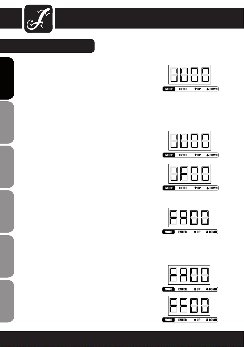
COLOUR JUMPING MODE
Press the MODE button repeatedly if necessary to select the Colour Jumping
Mode (JXXX). Press ENTER (2. digit blinks) to select the 15 colour jumping
ENGLISHDEUTSCHFRANCAIS
function (JUXX) or the strobe function (JFXX) by using the UP and DOWN
buttons.
Press ENTER again (3. and 4. digit blink) to adjust jumping speed (JU00 JU99) and strobe speed (JF00 - JF99) by using the UP and DOWN buttons.
Press ENTER to conrm.
Note: It is possible to use the colour jumping function and the strobe function
simultaneously.
RGBW 15 COLOUR
Jumping speed JU00 - JU99
STROBE
Speed JF00 - JF99
COLOUR FADING MODE
Press the MODE button repeatedly if necessary to select the Colour Fading
ESpAñoLpoLSKIITALIANo
Mode (FXXX). Press ENTER (2. digit blinks) to select the 15 colour fading
function (FAXX) or the strobe function (FFXX) by using the UP and DOWN
buttons. Press ENTER again (3. and 4. digit blink) to adjust fading speed
(FA00 - FA99) and strobe speed (FF00 - FF99) by using the UP and DOWN
buttons. Press ENTER to conrm.
Note: It is possible to use the colour fading function and the strobe function
simultaneously.
FRANCAISFRANCAIS FRANCAISFRANCAIS
RGBW 15 COLOUR
Fading speed FA00 - FA99
STROBE
Speed FF00 - FF99
10 11

AUTO MODE
Press the MODE button repeatedly if necessary to select the Auto Mode.
The unit changes between Colour Jumping Mode and Colour Fading Mode
automatically. The colour jumping and fading speed can be preadjusted by
using the speed settings of the Colour Jumping and Colour Fading Modes.
SLAVE MODE
Press the MODE button repeatedly if necessary to enter the Slave Mode.
Link slave units and the master unit (exclusively standalone modes) via
DMX cables. The slave unit will follow in sequence with the master unit.
MODE SELECTION:
FRANCAISFRANCAIS FRANCAISFRANCAIS
SOUND CONTROL MODE
Press the MODE button repeatedly if necessary to select the Sound Control
Mode (SUXX). The unit will follow the beat of the music thanks to the built
in microphone. Press ENTER again (3. and 4. digit blink) to adjust the sensitivity of the microphone (SU00 - SU99) by using the UP and DOWN buttons.
Press ENTER to conrm.
DMX MODE SELECTION
Press the MODE button to enter DMX MODE SELECTION (repeatedly if necessary). Press ENTER (1st digit blinks) and select the desired DMX mode
by using the UP and DOWN buttons. Press ENTER again to conrm.
Note: See the description of the different DMX modes on the following
pages of this manual.
DMX ADDRESS SETTING MODE
Press the MODE button repeatedly if necessary to enter the DMX Address
Setting Mode (AXXX).
Press ENTER to access edit mode (the last 3 digits blink) and select the
desired DMX start address by using the UP and DOWN buttons (A001 A512). Press ENTER to conrm.
NOTE:
The LED display automatically turns off after about 1 minute and turns on
again by pressing any of the 4 buttons.
FRANCAISDEUTSCHENGLISH
ITALIANOPOLSKIESPAÑOL

DMX CONTROL MODE:
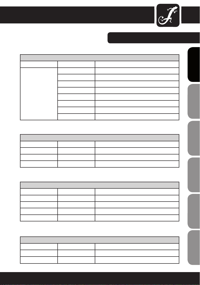
2 CHANNEL MODE
CHANNEL VALUE FUNCTION
ENGLISHDEUTSCHFRANCAIS
ESpAñoLpoLSKIITALIANo
FRANCAISFRANCAIS FRANCAISFRANCAIS
CH1 000 - 255 Master dimmer (0-100 %)
CH2 000 - 016
3 CHANNEL MODE 1
CHANNEL VALUE FUNCTION
CH1 000 - 255 Master dimmer (0-100 %)
CH2 000 - 255 Strobe (0-100%)
CH3 000 - 080 Colour-Macro
017 - 033
034 - 050
051 - 067
068 - 084
085 - 101
102 - 118
119 - 135
136 - 152
153 - 169
170 - 186
187 - 203
204 - 220
221 - 237
238 - 255
000 - 004 Blackout
005 - 010 Red
011 - 015 Green
016 - 020 Blue
021 - 025 White
026 - 030 Yellow
031 - 035 Cyan
036 - 040 Magenta
041 - 045 Pink
046 - 050 Bright Green
051 - 055 Lavender
Red
Green
Blue
White
Orange
Cyan
Lavender
Pink
Bright Green
Magenta
Pale Pink
Amber
Bright Magenta
Pale Cyan
Warm White
12 13
DMX CONTROL MODE:
3 CHANNEL MODE 1
CHANNEL VALUE FUNCTION
056 - 060 Pale Pink
061 - 065 Amber
066 - 070 Bright Magenta
071 - 075 Pale Cyan
076 - 080 Warm White
081 - 150 Colour Jumping Speed: slowest (081), fastest (150)
151 - 220 Colour Fading Speed: slowest (151), fastest (220)
221 - 255 Sound Control (Mic Sensitivity)
3 CHANNEL MODE 2
CHANNEL VALUE FUNCTION
CH1 000 - 255 RED (0-100%)
CH2 000 - 255 GREEN (0-100%)
CH3 000 - 255 BLUE (0-100%)
FRANCAISFRANCAIS FRANCAISFRANCAIS
FRANCAISDEUTSCHENGLISH
4 CHANNEL MODE
CHANNEL VALUE FUNCTION
CH1 000 - 255 RED (0-100%)
CH2 000 - 255 GREEN (0-100%)
CH3 000 - 255 BLUE (0-100%)
CH4 000 - 255 WHITE (0-100%)
7 CHANNEL MODE
CHANNEL VALUE FUNCTION
CH1 000 - 255 Master dimmer (0-100 %)
CH2 000 - 255 Strobe (0-100%)
ITALIANOPOLSKIESPAÑOL
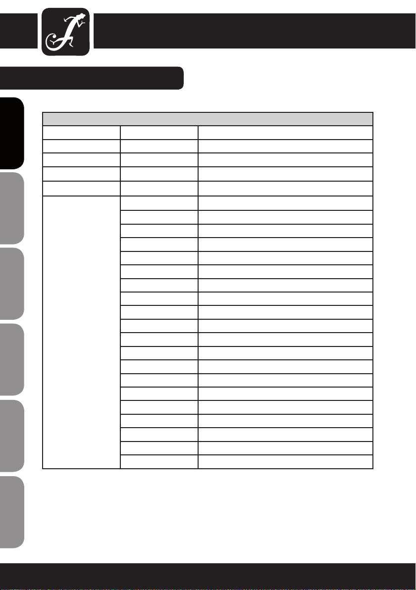
DMX CONTROL MODE:
7 CHANNEL MODE
CHANNEL VALUE FUNCTION
ENGLISHDEUTSCHFRANCAIS
ESpAñoLpoLSKIITALIANo
FRANCAISFRANCAIS FRANCAISFRANCAIS
CH3 000 - 255 RED (0-100%)
CH4 000 - 255 GREEN (0-100%)
CH5 000 - 255 BLUE (0-100%)
CH6 000 - 255 WHITE (0-100%)
CH7 000 - 080 Colour-Macro
000 - 004 Blackout / Colourmix CH3 - CH6
005 - 010 Red
011 - 015 Green
016 - 020 Blue
021 - 025 White
026 - 030 Yellow
031 - 035 Cyan
036 - 040 Magenta
041 - 045 Pink
046 - 050 Bright Green
051 - 055 Lavender
056 - 060 Pale Pink
061 - 065 Amber
066 - 070 Bright Magenta
071 - 075 Pale Cyan
076 - 080 Warm White
081 - 150 Colour Jumping Speed: slowest (081), fastest (150)
151 - 220 Colour Fading Speed: slowest (151), fastest (220)
221 - 255 Sound Control (Mic Sensitivity)
DAISY CHAIN CONNECTION
1) Connect the (male) 3 pin connector side of the DMX cable to the output (female) 3 pin connector of the rst xture
2) Connect the end of the cable coming from the rst xture which will have a (female) 3 pin connector to the
input connector of the next xture consisting of a (male) 3 pin connector. Proceed to connect from the output as
stated above to the input of the following fixture and so on.
14 15

SPECIFICATIONS:
18 X 8W QUAD COLOUR LED PAR CAN RGBW WEIGHT & DIMENSIONS (WITHOUT BRACKET)
Length 255 mm
Width 230 mm
Height 220 mm
Weight 4,5 kg
Beam angle 25 °
POWER
Power consumption 170 W
AC input 110 V AC - 250 V AC / 50 Hz - 60 Hz
FUSE
Main F2A, 250V
CONTROL & PROGRAMMING
DMX input 3-pin XLR male socket
DMX output Locking 3-pin XLR female socket
Protocols DMX-512 USITT
DMX channel modes 2 CH, 3 CH1, 3 CH2, 4 CH, 7 CH
FRANCAISFRANCAIS FRANCAISFRANCAIS
FRANCAISDEUTSCHENGLISH
ITALIANOPOLSKIESPAÑOL
DMX LINKING:
DMX-512
DMX (Digital Multiplex) is a universal protocol used as a form of communication between intelligent xtures
and controllers. A DMX controller sends DMX data instructions from the controller to the xture. DMX data
are sent as serial data that travel from xture to xture via the “DMX IN“ and “DMX OUT” XLR terminals
located on all DMX xtures (most controllers only have a “DMX OUT” terminal).
ENGLISHDEUTSCHFRANCAIS
DMX LINKING:
DMX is a language allowing all makes and models of different manufactures to be linked together and operate
from a single controller, as long as all xtures and the controller are DMX compliant. To ensure proper DMX data
transmission, when using several DMX xtures try to use the shortest cable path possible. The order in which
xtures are connected in a DMX line does not inuence the DMX addressing. For example a xture assigned to a
DMX address of 1 may be placed anywhere in a DMX line, at the beginning, at the end, or anywhere in the middle. When a xture is assigned a DMX address of 1, the DMX controller knows to send DATA assigned to address 1
to that unit, no matter where it is located in the DMX chain.
ESpAñoLpoLSKIITALIANo
FRANCAISFRANCAIS FRANCAISFRANCAIS
Please check out our comprehensive DMX cable choices out of our Adam Hall product lines 3 STAR, 4 STAR and 5 STAR
Keep in mind that DMX connections must be daisy chained. To avoid malfunction, DMX cabling should not be
divided in several lines without the use of an active splitter.
16 17

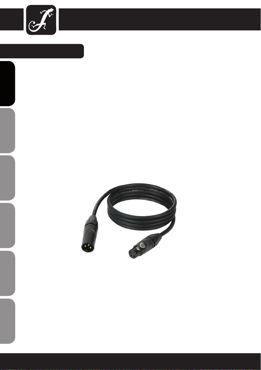
DMX CABLES:
NOTICE:
• Be sure to follow gures 2 & 3 when making your own cables. Do not connect the cable’s shield conductor to
the ground lug or allow the shield conductor to come in contact with the XLR’s outer casing. Grounding the shield
could cause a short circuit and erratic behaviour.
common
DMX-512 out
3-pin XLR
DMX-512 in
3-pin XLR
SPECIAL NOTE: LINE TERMINATION:
• When longer runs of cable are used, you may need to use a terminator on the last unit to avoid erratic behaviour.
Termination reduces signal transmission problems and interference. It is always advisable to
connect a DMX terminator, (resistance 120 Ohm
1/4 W) between pin 2 (DMX-) and pin 3 (DMX+)
of the last fixture.
Using a cable terminator (Art. No. K3DMXT3) will decrease the possibilities of erratic behaviour.
• Some manufactures use 5-pin XLR connectors for data transmission in place of 3-pin. 5-Pin XLR xtures may
be implemented in a 3-pin XLR DMX line. When inserting standard 5-pin XLR connectors in to a 3-pin line a cable
adaptor must be used. The chart below details the correct cable conversion.
5-Pin XLR (socket)
Pin 1: GND (screen)
Pin 2: Signal (-)
Pin 3: Signal (+)
Pin 4: N/C
Pin 5: N/C
3-Pin XLR (socket)
Pin 1: GND (screen)
Pin 2: Signal (-)
Pin 3: Signal (+)
3-Pin XLR (socket)
Pin 1: GND (screen)
Pin 2: Signal (-)
Pin 3: Signal (+)
5-Pin XLR (socket)
Pin 1: GND (screen)
Pin 2: Signal (-)
Pin 3: Signal (+)
Pin 4: N/C
Pin 5: N/C
FRANCAISFRANCAIS FRANCAISFRANCAIS
FRANCAISDEUTSCHENGLISH
ITALIANOPOLSKIESPAÑOL

MANUFACTURER´S DECLARATIONS:
LIMITED WARRANTY
This Limited Warranty applies to the Adam Hall, LD Systems, LD Premium, Defender, Palmer, Cameo and Eminence
branded products.
ENGLISHDEUTSCHFRANCAIS
The statutory warranty rights towards the seller are not affected by this guarantee. In fact, it justifies, additional
independent warranty claims towards Adam Hall.
Adam Hall warrants that the Adam Hall product you have purchased from Adam Hall or from an Adam Hall authorized reseller is free from defects in materials or workmanship under normal use for a period of 2 or 5 years from
the date of purchase.
The Limited Warranty Period starts on the date of purchase. In order to receive warranty services you are required
to provide proof of the purchase date. Your dated sales or delivery receipt, showing the date of purchase, is your
proof of the purchase date. Should products of the brands named above be in need of repair within the limited warranty period, you are entitled to warranty services according to the terms and conditions stated in this document.
This Limited Warranty extends only to the original purchaser of this Adam Hall branded product and is not transferable to anyone who obtains ownership of the Adam Hall branded product from the original purchaser. During
the Limited Warranty Period, Adam Hall will repair or replace the defective component parts or the product. All
component parts or hardware products removed under this Limited Warranty become the property of Adam Hall.
In the unlikely event that your Adam Hall product has a recurring failure, Adam Hall, at its discretion, may elect to
provide you with a replacement unit of Adam Hall´s choice that is at least equivalent to your Adam Hall branded
product in hardware performance.
Adam Hall does not warrant that the operation of this product will be uninterrupted or error-free. Adam Hall is not
ESpAñoLpoLSKIITALIANo
responsible for damage that occurs as a result of your failure to follow the instructions included with the Adam
Hall branded product.
This Limited Warranty does not apply,
- to wear parts (e.g. accumulator)
- to any product from which the serial number has been removed or that has been damaged or rendered defective as the result of an accident
FRANCAISFRANCAIS FRANCAISFRANCAIS
- in case of, misuse, abuse, or other external causes
- by operation outside the usage parameters stated in the user´s documentation shipped with the product by use
of spare parts not manufactured or sold by Adam Hall
- by modication or service by anyone other than Adam Hall
These terms and conditions constitute the complete and exclusive warranty agreement between you and Adam
Hall regarding the Adam Hall branded product you have purchased.
18 19

LIMITATION OF LIABILITY
If your Adam Hall branded hardware product fails to work as warranted above, your sole and exclusive remedy
shall be repair or replacement. Adam Halls’ maximum liability under this limited warranty is expressly limited
to the lesser of the price you have paid for the product or the cost of repair or replacement of any hardware
components that malfunction in conditions of normal use.
Adam Hall is not liable for any damages caused by the product or the failure of the product, including any lost
prots or savings or special, incidental, or consequential damages. Adam Hall is not liable for any claim made by
a third party or made by you for a third party.
This limitation of liability applies whether damages are sought, or claims are made, under this Limited Warranty
or as a tort claim (including negligence and strict product liability), a contract claim, or any other claim. This limitation of liability cannot be waived or amended by any person. This limitation of liability will be effective even if
you have advised Adam Hall of an authorized representative of Adam Hall of the possibility of any such damages.
This limitation of liability however, will not apply to claims for personal injury.
This Limited Warranty gives you specific legal rights. You may also have other rights that may vary from state to
state or from country to country. You are advised to consult applicable state or country laws for a full determination of your rights.
REQUESTING WARRANTY-SERVICE
To request warranty service for the product, contact Adam Hall or the Adam Hall authorized reseller from which
you purchased the product.
EC DECLARATION OF CONFORMITY
These devices meet the essential requirements and further relevant specications of Directives 2004/108/EC
(EMC) and 2006/95/EC (LVD). For more information, see www.adamhall.com.
CORRECT DISPOSAL OF THIS PRODUCT (ELECTRICAL WASTE)
(Applicable in the European Union and other European countries with separate collection systems)
This marking shown on the product or its literature, indicates that it should not be disposed with other household
wastes at the end of its working life. To prevent possible harm to the environment or human health from uncontrolled waste disposal, please separate this from other types of wastes and recycle it responsibly to promote the
sustainable reuse of material resources.
FRANCAISFRANCAIS FRANCAISFRANCAIS
FRANCAISDEUTSCHENGLISH
Household users should contact either the retailer where they purchased this product, or their local government
office, for details on where and how they can recycle this item in an enviromentally friendly manner.
Business users should contact their supplier and check the terms and conditions of the purchase contract. This
product should not be mixed with other commercial wastes for disposal.
ITALIANOPOLSKIESPAÑOL

MANUFACTURER´S DECLARATIONS:
WEEE-DECLARATION
Your LD-Systems product was developed and manufactured with high quality materials and components wich
can be recycled and/or reused. This symbol indicates that electrical and electronic equipment must be disposed
ENGLISHDEUTSCHFRANCAIS
of separately from normal waste at the end of its operational lifetime.
Please dispose of this product by bringing it to your local collection point or recycling centre for such equipment.
This will help to protect the environment in which we all live.
BATTERIES AND ACCUMULATORS
The supplied batteries or rechargeable batteries can be recycled. Please dispose of them as special waste or
return them to your specialist dealer. In order to protect the environment, only dispose exhausted batteries.
ECOLOGY AND ENERGY SAVING
Saving electric energy helps to protect the environment. Please turn off all electrical equipment when it is not in
use. To avoid power consumption in idle mode, disconnect all electrical equipment from mains when not in use.
ESpAñoLpoLSKIITALIANo
FRANCAISFRANCAIS FRANCAISFRANCAIS
Adam Hall GmbH, all rights reserved. The technical data and the functional product characteristics can be subject
to modifications. The photocopying, the translation, and all other forms of copying of fragments or of the integral-
ity of this user’s manual is prohibited.
20 21

FRANCAISFRANCAIS FRANCAISFRANCAIS
FRANCAISDEUTSCHENGLISH
ITALIANOPOLSKIESPAÑOL

ENGLISHDEUTSCHFRANCAIS
Wir freuen uns, dass Sie sich für ein Produkt von Cameo Light entschieden haben!
Dieses Gerät wurde unter hohen Qualitätsanforderungen entwickelt und gefertigt, um viele Jahre einen reibungslosen Betrieb zu gewährleisten.
Bitte lesen Sie diese Bedienungsanleitung sorgfältig, damit Sie Ihren neuen Scheinwerfer von Cameo Light
schnell optimal einsetzen können.
Weitere Informationen über Cameo Light erhalten Sie auf unserer Website WWW.CAMEOLIGHT.COM.
ESpAñoLpoLSKIITALIANo
FRANCAISFRANCAIS FRANCAISFRANCAIS
22 23

STUDIO PAR 64 CAN
18 X 8W QUAD COLOUR LED RGBW PAR SCHEINWERFER
CLPST64Q8W
FRANCAISFRANCAIS FRANCAISFRANCAIS
FRANCAISDEUTSCHENGLISH
ITALIANOPOLSKIESPAÑOL

SICHERHEITSHINWEISE:
1. Lesen Sie diese Anleitung bitte sorgfältig durch.
2. Bewahren Sie alle Informationen und Anleitungen an einem sicheren Ort auf.
3. Befolgen Sie die Anweisungen.
ENGLISHDEUTSCHFRANCAIS
4. Beachten Sie alle Warnhinweise. Entfernen Sie keine Sicherheitshinweise oder andere Informationen vom
Gerät.
5. Verwenden Sie das Gerät nur in der vorgesehenen Art und Weise.
6. Verwenden Sie ausschließlich stabile und passende Stative bzw. Befestigungen (bei Festinstallationen). Stellen
Sie sicher, dass Wandhalterungen ordnungsgemäß installiert und gesichert sind. Stellen Sie sicher, dass das
Gerät sicher installiert ist und nicht herunterfallen kann.
7. Beachten Sie bei der Installation die für Ihr Land geltenden Sicherheitsvorschriften.
8. Installieren und betreiben Sie das Gerät nicht in der Nähe von Heizkörpern, Wärmespeichern, Öfen oder
sonstigen Wärmequellen. Sorgen Sie dafür, dass das Gerät immer so installiert ist, dass es ausreichend gekühlt
wird und nicht überhitzen kann.
9. Platzieren Sie keine Zündquellen wie z. B brennende Kerzen auf dem Gerät.
10. Die Lüftungsschlitze dürfen nicht blockiert werden
11. Betreiben Sie das Gerät nicht in unmittelbarer Nähe von Wasser. Bringen Sie das Gerät nicht mit brennbaren
Materialien, Flüssigkeiten oder Gasen in Berührung.
12. Sorgen Sie dafür, dass kein Tropf- oder Spritzwasser in das Gerät eindringt. Stellen Sie keine mit Flüssigkeit
gefüllten Behältnisse wie Vasen oder Trinkgefäße auf das Gerät.
13. Sorgen Sie dafür, dass keine Gegenstände in das Gerät fallen können.
14. Betreiben Sie das Gerät nur mit dem vom Hersteller empfohlenen und vorgesehenen Zubehör.
15. ACHTUNG: Wenn das Stromkabel des Geräts mit einem Schutzkontakt ausgestattet ist, muss es an einer
Steckdose mit Schutzleiter angeschlossen werden. Deaktivieren Sie niemals den Schutzleiter des mitgelieferten
Kaltgerätekabels.
16. Schalten Sie das Gerät nicht sofort ein, wenn es starken Temperaturschwankungen ausgesetzt war (beispielsweise nach dem Transport). Feuchtigkeit und Kondensat könnten das Gerät beschädigen. Schalten Sie das
ESpAñoLpoLSKIITALIANo
Gerät erst ein, wenn es Zimmertemperatur erreicht hat.
17. Öffnen Sie das Gerät nicht und verändern Sie es nicht.
18. Bevor Sie das Gerät an die Steckdose anschließen, prüfen Sie zuerst, ob die Spannung und die Frequenz
des Stromnetzes mit den auf dem Gerät angegebenen Werten übereinstimmen. Verfügt das Gerät über einen
Spannungswahlschalter, schließen Sie das Gerät nur an die Steckdose an, wenn die Gerätewerte mit den Werten
des Stromnetzes übereinstimmen.
Wenn das mitgelieferte Netzkabel nicht in Ihre Netzsteckdose passt, wenden Sie sich an Ihren Elektriker.
FRANCAISFRANCAIS FRANCAISFRANCAIS
19. Treten Sie nicht auf das Kaltgerätekabel. Sorgen Sie dafür, dass das Kaltgerätekabel speziell an der Netz- und
der Gerätebuchse nicht geknickt wird.
20. Überprüfen Sie nach dem Anschluss des Geräts alle Kabelwege, um Schäden oder Unfälle, z. B. durch
Stolperfallen zu vermeiden.
21. Achten Sie bei der Verkabelung des Geräts immer darauf, dass das Netzkabel stets frei zugänglich ist.
Ziehen Sie immer den Netzstecker, wenn das Gerät nicht benutzt wird, oder Sie das Gerät reinigen möchten.
Ziehen Sie das Kaltgerätekabel immer am Stecker und nicht am Kabel aus der Steckdose.
22. Schalten Sie das Gerät möglichst nicht schnell hintereinander ein und aus, da sonst die Lebensdauer des
Geräts beeinträchtigt werden könnte.
23. WICHTIGER HINWEIS: Ersetzen Sie die Sicherung ausschließlich durch eine Sicherung des gleichen Typs
24 25

und mit gleichen Werten. Sollte die Sicherung wiederholt auslösen, wenden Sie sich bitte an ein autorisiertes
Servicezentrum.
24. Um das Gerät vollständig vom Stromnetz zu trennen, entfernen Sie das Netzkabel.
25. Wenn Ihr Gerät mit einem Volex-Netzanschluss bestückt ist, muss der passende Volex-Gerätestecker
entsperrt werden, bevor er entfernt werden kann. Das bedeutet aber auch, dass das Gerät durch eine Ziehen
am Kaltgerätekabel verrutschen kann, wodurch Personen verletzt werden und/oder andere Schäden auftreten
können. Verlegen Sie Ihre Kabel daher immer sorgfältig.
26. Entfernen Sie das Netzkabel bei Gefahr eines Blitzschlags oder wenn Sie das Gerät länger nicht verwenden.
27. Achten Sie beim Transport darauf, dass das Gerät nicht herunterfallen und dabei möglicherweise Sach- und
Personenschäden verursachen kann.
28. Wenn Ihr Gerät nicht mehr ordnungsgemäß funktioniert, Flüssigkeiten oder Gegenstände in das Geräteinnere gelangt sind oder das Gerät anderweitig beschädigt wurde, schalten Sie es sofort aus und ziehen Sie den
Stecker. Dieses Gerät darf nur von autorisiertem Fachpersonal repariert werden.
29. Verwenden Sie zur Reinigung des Geräts ein trockenes Tuch.
30. Beachten Sie alle in Ihrem Land geltenden Entsorgungsgesetze. Trennen Sie bei der Entsorgung bitte Kunststoff und Papier bzw. Kartonagen voneinander.
31. Kunststoffbeutel müssen außer Reichweite von Kindern aufbewahrt werden.
CAUTION
RISK OF ELECTRIC SHOCK
ACHTUNG:
Entfernen Sie niemals die Abdeckung, da sonst das Risiko eines elektrischen Schlages besteht. Im Inneren des
Geräts befinden sich keine Teile, die vom Bediener repariert oder gewartet werden können. Lassen Sie Reparaturen ausschließlich von qualifiziertem Service-Personal durchführen.
Das gleichschenkelige Dreieck mit dem Blitzsymbol kennzeichnet
nicht-isolierte, „gefährliche“ Spannungen im Gerät,
die einen für die Gesundheit gefährlichen Stromschlag verursachen können.
DO NOT OPEN
FRANCAISFRANCAIS FRANCAISFRANCAIS
FRANCAISDEUTSCHENGLISH
Das gleichschenkelige Dreieck mit dem Ausrufezeichen kennzeichnet wichtige Bedienungs- und
Wartungshinweise.
ITALIANOPOLSKIESPAÑOL

EINFÜHRUNG:
STEUERUNGSFUNKTIONEN
18 X 8 W QUAD COLOUR LED RGBW PAR SCHEINWERFER
ENGLISHDEUTSCHFRANCAIS
(CLPST64Q8W)
• DMX-Modi: 2 CH, 3 CH1, 3 CH2, 4 CH, 7 CH
• Rot, Grün, Blau und Weiß individuell steuerbar (RGBW in 1)
FEATURES
• 18 Ultra-leuchtstarke QUAD-Color-LEDs (8W)
• Musiksteuerung über eingebautes Mikrofon
• Farbwechselgeschwindigkeit und Stroboskopeffekt über Bedienpanel steuerbar
• Multicolor-Farbwechsel
• Master/Slave-Funktionalität
• Robustes, kompaktes Gehäuse
• Leistungsaufnahme: 170 W
• 25° Abstrahlwinkel
• Longlife-LEDs mit besonders langer Lebensdauer
BEDIENUNG
Der Cameo LED CAN ist ein über DMX-512 steuerbarer, hochefzienter Farbscheinwerfer mit ultrahellen LEDs.
Die Intensität der vier Farben (Rot, Grün, Blau und Weiß) lässt sich einzeln steuern, wodurch unendlich viele
verschiedene Farbnuancen ermöglicht werden. Der Cameo LED-Strahler lässt sich sowohl einzeln als auch im
Master/Slave-Betrieb, per Musiksteuerung und via DMX-512-Protokoll betreiben.
ESpAñoLpoLSKIITALIANo
FRANCAISFRANCAIS FRANCAISFRANCAIS
26 27

RÜCKSEITE:
FRANCAISFRANCAIS FRANCAISFRANCAIS
FRANCAISDEUTSCHENGLISH
POWER
110V-250V AC
50Hz~60Hz
F2A / 250V
ITALIANOPOLSKIESPAÑOL

MODUS AUSWÄHLEN:
STATISCHE FARBE
Drücken Sie die MODE-Taste (falls erforderlich mehrmals), um die Betriebsart „Statische Farbe“ (CXXX) auszuwählen. Bestätigen Sie mit ENTER (2.
ENGLISHDEUTSCHFRANCAIS
Ziffer blinkt) und wählen Sie anschließend mit den Tasten UP und DOWN die
gewünschte Farbe bzw. den Stroboskopmodus aus. (C1 = Rot, C2 = Grün,
C3 = Blau, C4 = Weiß und CF = Stroboskopeffekt).
Drücken Sie erneut die ENTER-Taste (3. und 4. Ziffer blinkt), und stellen
Sie mit den Tasten UP und DOWN die Helligkeit der zuvor ausgewählten
Farbe (CX00 - CX99) und die Stroboskopgeschwindigkeit (CF00 - CF99) ein.
Bestätigen Sie mit ENTER.
Beispiele: Wenn Sie C1, C2, C3 und C4 auf 0 setzen, sind alle LEDs des Quad
Par Can aus (Blackout).
Wenn Sie C1 auf 99 und C2, C3 und C4 auf 0 setzen, leuchtet der Scheinwerfer nur rot (100%).
ROT
Helligkeit C100 - C199
GRÜN
Helligkeit C200 - C299
ESpAñoLpoLSKIITALIANo
BLAU
Helligkeit C300 - C399
WEISS
FRANCAISFRANCAIS FRANCAISFRANCAIS
Helligkeit C400 - C499
STROBOSKOPEFFEKT
Geschwindigkeit CF00 - CF99
28 29

MODUS AUSWÄHLEN:
COLOUR MACRO MODUS (15 FARBEN)
(AB REVISION 2)
Drücken Sie die MODE-Taste (falls erforderlich mehrmals), um die Betriebsart „Colour Macro“ (CMXX) auszuwählen. Bestätigen Sie Ihre Auswahl mit
ENTER und wählen Sie dann mit den Tasten UP und DOWN die gewünschte
Farbe aus. Bestätigen Sie Ihre Auswahl mit ENTER.
1. ROT
2. GRÜN
FRANCAISFRANCAIS FRANCAISFRANCAIS
3. BLAU
4. WEISS
5. GELB
6. TÜRKIS
7. LAVENDELBLAU
8. PINK
9. HELLGRÜN
10. VIOLETT
11. ZARTROSA
12. BERNSTEINGELB
13. HELLVIOLETT
14. HELLTÜRKIS
15. WARMWEISS
FRANCAISDEUTSCHENGLISH
ITALIANOPOLSKIESPAÑOL

MODUS AUSWÄHLEN:
FARBWECHSEL
Drücken Sie die MODE-Taste (falls erforderlich mehrmals) und wählen Sie
das gewünschte Farbwechselprogramm (JXXX) aus. Bestätigen Sie mit
ENGLISHDEUTSCHFRANCAIS
ENTER (2. Ziffer blinkt) und wählen Sie anschließend mit den Tasten UP und
DOWN den 15-Farben-Modus (JUXX) oder den Stroboskop-Modus (JFXX)
aus.
Drücken Sie erneut die ENTER-Taste (3. und 4. Ziffer blinkt) und stellen Sie
mit den Tasten UP und DOWN die Wechselgeschwindigkeit (JU00 - JU99)
und die Stroboskopgeschwindigkeit (JF00 - JF99) ein. Bestätigen Sie mit
ENTER.
Hinweis: Farbwechsel-Funktion und Stroboskopeffekt können gleichzeitig
aktiviert werden.
RGBW 15 FARBEN
Wechselgeschwindigkeit JU00 - JU99
STROBOSKOPEFFEKT
Geschwindigkeit JF00 - JF99
ÜBERBLENDEN
Drücken Sie die MODE-Taste (falls erforderlich mehrmals) und wählen Sie
ESpAñoLpoLSKIITALIANo
den gewünschten Überblenden-Modus (FXXX) aus. Bestätigen Sie mit ENTER
(2. Ziffer blinkt) und wählen Sie anschließend mit den Tasten UP und DOWN
den 15-Farben-Überblenden-Modus (FAXX) oder den Stroboskop-Modus
(FFXX) aus. Drücken Sie erneut die ENTER-Taste (3. und 4. Ziffer blinkt)
und stellen Sie mit den Tasten UP und DOWN die Überblendgeschwindigkeit (FA00 - FA99) und die Stroboskopgeschwindigkeit (FF00 - FF99) ein.
Bestätigen Sie mit ENTER.
Hinweis: Überblenden-Funktion und Stroboskopeffekt können gleichzeitig
FRANCAISFRANCAIS FRANCAISFRANCAIS
aktiviert werden.
RGBW 15 FARBEN
Überblendgeschwindigkeit FA00 - FA99
STROBOSKOPEFFEKT
Geschwindigkeit FF00 - FF99
30 31

MODUS AUSWÄHLEN:
AUTO-MODUS
Drücken Sie die MODE-Taste (falls erforderlich mehrmals) und wählen
Sie den Auto-Modus aus. In dieser Betriebsart wird automatisch zwischen
Farbwechsel- und Überblenden-Modus gewechselt. Die Farbwechsel- bzw.
Überblendgeschwindigkeit wird über die Einstellungen des jeweiligen
Modus festgelegt.
SLAVE-MODUS
Drücken Sie die MODE-Taste (falls erforderlich mehrmals) und wählen Sie
den Slave-Modus aus.
Verbinden Sie die Slave-Einheiten und die Master-Einheit (ausschließlich
Standalone-Modi) mit einem DMX-Kabel. Nun folgt die Slave-Einheit der
Master-Einheit.
MUSIKSTEUERUNG
Drücken Sie die MODE-Taste (falls erforderlich mehrmals) und wählen Sie
den Musiksteuerungs-Modus (SUXX) aus. Nun wird die Lichtanlage über
das eingebaute Mikrofon gesteuert und folgt dem Takt der Musik. Drücken
Sie erneut die ENTER-Taste (3. und 4. Ziffer blinkt) und stellen Sie mit den
Tasten UP und DOWN die Mikrofon-Empndlichkeit (SU00 - SU99) ein.
Bestätigen Sie mit ENTER.
DMX-MODUS AUSWÄHLEN
Drücken Sie die MODE-Taste (falls erforderlich mehrmals), um den
DMX-MODUS auszuwählen. Bestätigen Sie mit ENTER (1. Ziffer blinkt) und
wählen Sie anschließend mit den Tasten UP und DOWN den gewünschten
DMX-Modus aus. Bestätigen Sie mit ENTER.
Hinweis: Auf den folgenden Seiten werden die verschiedenen DMX-Modi
erklärt.
DMX-ADRESSE EINSTELLEN
Drücken Sie die MODE-Taste (falls erforderlich mehrmals) und stellen Sie
die DMX-Adresse (AXXX) ein.
Drücken Sie ENTER, um in den Bearbeitungsmodus zu gelangen (die
letzten drei Ziffern blinken) und wählen Sie anschließend mit den Tasten
UP und DOWN die gewünschte DMX-Startadresse (A001 - A512) aus.
Bestätigen Sie mit ENTER.
FRANCAISFRANCAIS FRANCAISFRANCAIS
FRANCAISDEUTSCHENGLISH
ITALIANOPOLSKIESPAÑOL
ANMERKUNG:
Die LED-Anzeige wird nach etwa einer Minute automatisch ausgeschaltet
und schaltet sich wieder ein, sobald eine der vier Tasten gedrückt wird.

DMX MODUS:
2-KANAL-MODUS
CHANNEL (KANAL) WERT FUNKTION
ENGLISHDEUTSCHFRANCAIS
3-KANAL-MODUS 1
CHANNEL (KANAL) WERT FUNKTION
ESpAñoLpoLSKIITALIANo
FRANCAISFRANCAIS FRANCAISFRANCAIS
CH1 000 - 255 Master-Dimmer (0 - 100%)
CH2 000 - 016
017 - 033
034 - 050
051 - 067
068 - 084
085 - 101
102 - 118
119 - 135
136 - 152
153 - 169
170 - 186
187 - 203
204 - 220
221 - 237
238 - 255
CH1 000 - 255 Master-Dimmer (0 - 100%)
CH2 000 - 255 Stroboskop (0 - 100%)
CH3 000 - 080 Colour-Macro
000 - 004 Blackout
005 - 010 Rot
011 - 015 Grün
016 - 020 Blau
021 - 025 Weiß
026 - 030 Gelb
031 - 035 Türkis
036 - 040 Violett
041 - 045 Pink
046 - 050 Hellgrün
051 - 055 Lavendelblau
Rot
Grün
Blau
Weiß
Orange
Türkis
Lavendelblau
Pink
Hellgrün
Violett
Zartrosa
Bernsteingelb
Hellviolett
Helltürkis
Warmweiß
32 33

3-KANAL-MODUS 1
CHANNEL (KANAL) WERT FUNKTION
056 - 060 Zartrosa
061 - 065 Bernsteingelb
066 - 070 Hellviolett
071 - 075 Helltürkis
076 - 080 Warmweiß
081 - 150 Farbwechselgeschwindigkeit: langsamste (081),
schnellste (150)
151 - 220 Überblendgeschwindigkeit: langsamste (151),
schnellste (220)
221 - 255 Musiksteuerung (Mikrofonempfindlichkeit)
3-KANAL-MODUS 2
CHANNEL (KANAL) WERT FUNKTION
CH1 000 - 255 ROT (0 - 100%)
CH2 000 - 255 GRÜN (0 - 100%)
CH3 000 - 255 BLAU (0 - 100%)
DMX MODUS:
FRANCAISFRANCAIS FRANCAISFRANCAIS
FRANCAISDEUTSCHENGLISH
4-KANAL-MODUS
CHANNEL (KANAL) WERT FUNKTION
CH1 000 - 255 ROT (0 - 100%)
CH2 000 - 255 GRÜN (0 - 100%)
CH3 000 - 255 BLAU (0 - 100%)
CH4 000 - 255 WEISS (0 - 100%)
7-KANAL-MODUS
CHANNEL (KANAL) WERT FUNKTION
CH1 000 - 255 Master-Dimmer (0 - 100%)
CH2 000 - 255 Stroboskop (0 - 100%)
ITALIANOPOLSKIESPAÑOL

DMX MODUS:
7-KANAL-MODUS
CHANNEL (KANAL) WERT FUNKTION
ENGLISHDEUTSCHFRANCAIS
ESpAñoLpoLSKIITALIANo
FRANCAISFRANCAIS FRANCAISFRANCAIS
CH3 000 - 255 ROT (0 - 100%)
CH4 000 - 255 GRÜN (0 - 100%)
CH5 000 - 255 BLAU (0 - 100%)
CH6 000 - 255 WEISS (0 - 100%)
CH7 000 - 080 Colour-Macro
000 - 004 Blackout / Colourmix CH3 - CH6
005 - 010 Rot
011 - 015 Grün
016 - 020 Blau
021 - 025 Weiß
026 - 030 Gelb
031 - 035 Türkis
036 - 040 Violett
041 - 045 Pink
046 - 050 Hellgrün
051 - 055 Lavendelblau
056 - 060 Zartrosa
061 - 065 Bernsteingelb
066 - 070 Hellviolett
071 - 075 Helltürkis
076 - 080 Warmweiß
081 - 150 Farbwechselgeschwindigkeit: langsamste (081),
schnellste (150)
151 - 220 Überblendgeschwindigkeit: langsamste (151),
schnellste (220)
221 - 255 Musiksteuerung (Mikrofonempfindlichkeit)
SERIELLE VERBINDUNG MEHRERER SCHEINWERFER
1) Verbinden Sie das eine Ende des DMX-Kabels (männlicher 3-Pol-Stecker) mit dem DMX-Ausgang (weibliche
3-Pol-Buchse) des ersten Scheinwerfers oder anderen DMX-Geräts.
2) Verbinden Sie das andere Ende (weiblicher 3-Pol-Stecker) des an den ersten Scheinwerfer angeschlossenen
DMX-Kabels mit dem DMX-Eingang (männliche 3-Pol-Buchse) des nächsten DMX-Geräts. Verbinden Sie den
DMX-Ausgang dieses Geräts in der gleichen Weise mit dem DMX-Eingang des nächsten Geräts und so weiter.
34 35

TECHNISCHE DATEN:
18 X 8 W QUAD COLOUR LED RGBW PAR SCHEINWERFER GEWICHT UND ABMESSUNGEN
Länge 255 mm (OHNE HALTERUNG)
Breite 230 mm (OHNE HALTERUNG)
Höhe 220 mm (OHNE HALTERUNG)
Gewicht 4,5 kg (OHNE HALTERUNG)
Abstrahlwinkel 25 °
POWER
Leistungsaufnahme 170 W
Stromversorgung 110 V AC - 250 V AC / 50 Hz - 60 Hz
SICHERUNG
Hauptsicherung F2A, 250 V
STEUERUNG & PROGRAMMIERUNG
DMX-Eingang XLR(m)-Buchse (3-Pol)
DMX-Ausgang Verriegelbare XLR(f)-Buchse (3-Pol)
Protokolle DMX-512 USITT
DMX-Modi: 2 CH, 3 CH1, 3 CH2, 4 CH, 7 CH
FRANCAISFRANCAIS FRANCAISFRANCAIS
FRANCAISDEUTSCHENGLISH
ITALIANOPOLSKIESPAÑOL

DMX-VERBINDUNG:
DMX-512
DMX (Digital Multiplex) ist die Bezeichnung für ein universelles Übertragungsprotokoll für die Kommunikation zwischen entsprechenden Geräten und Controllern. Ein DMX-Controller sendet DMX-Daten an das/die
angeschlossene(n) DMX-Gerät(e). Die DMX-Datenübertragung erfolgt stets als serieller Datenstrom, der über die
an jedem DMX-fähigen Gerät vorhandenen „DMX IN“- und „DMX OUT“-Anschlüsse (XLR-Steckverbinder) von
ENGLISHDEUTSCHFRANCAIS
einem angeschlossenen Gerät an das nächste weitergeleitet wird. (Die meisten Controller verfügen lediglich über
einen DMX-Ausgang.)
DMX-VERBINDUNG:
DMX ist die gemeinsame "Sprache", über die sich die unterschiedlichsten Gerätetypen und Modelle
verschiedener Hersteller miteinander verkoppeln und über einen zentralen Controller steuern lassen –
sofern sämtliche Geräte und der Controller DMX-kompatibel sind. Für eine optimale Datenübertragung
ist es erforderlich, die Verbindungskabel zwischen den einzelnen Geräten so kurz wie möglich zu halten.
Die Reihenfolge, in der die Geräte in das DMX-Netzwerk eingebunden sind, hat keinen Einfluss auf die
Addressierung. So kann sich das Gerät mit der DMX-Adresse 1 an einer beliebigen Position in der (seriellen)
DMX-Kette befinden, am Anfang, am Ende oder irgendwo in der Mitte. Wird einem Gerät die DMX-Adresse
1 zugewiesen, "weiß" der Controller, dass er alle der Adresse 1 zugeordneten Daten an dieses Gerät
senden soll – ungeachtet seiner Position im DMX-Verbund.
ESpAñoLpoLSKIITALIANo
FRANCAISFRANCAIS FRANCAISFRANCAIS
Eine umfangreiche Auswahl geeigneter Kabel finden Sie in den Adam Hall-Produktlinien 3 STAR, 4 STAR
und 5 STAR.
Bitte beachten Sie, dass DMX-Geräte grundsätzlich seriell verschaltet werden und die Verbindungen nicht
gesplittet werden können.
36 37
36

DMX-KABEL:
HINWEIS:
• Beachten Sie bei der Anfertigung eigener Kabel unbedingt die Abbildungen 2 und 3. Verbinden Sie auf
keinen Fall die Abschirmung des Kabels mit dem Massekontakt des Steckers, und achten Sie darauf, dass die
Abschirmung nicht mit dem XLR-Steckergehäuse in Kontakt kommt. Hat die Abschirmung Massekontakt, kann
dies zu Kurzschlüssen und Systemfehlern führen.
Übliche Verbindung
DMX-512-Ausgang
3-Pol-XLR
DMX-512-Eingang
3-Pol-XLR
BITTE BEACHTEN SIE: LEITUNGSABSCHLUSS (TERMINIERUNG):
• Bei längeren Kabelstrecken kann es sein, dass das letzte Gerät in der Kette einen Abschlusswiderstand
benötigt, um Systemfehlern vorzubeugen.
Die Verwendung eines Abschlusswiderstands
(Terminierung) reduziert Interferenzen und
andere Probleme bei der Signalübertragung.
Es ist immer ratsam, ein DMX-Abschlussmodul
(Widerstand 120 Ohm, 1/4 W) zwischen Pol 2
(DMX-) und Pol 3 (DMX+) des letzten Geräts in
der Kette einzufügen.
Dies wird durch ein Kabel-Abschlussmodul (Art.-Nr. K3DMXT3) erreicht.
• Einige Hersteller verwenden für die Datenübertragung keine 3-Pol-XLR-Steckverbinder, sondern 5-PolVersionen. Geräte mit 5-Pol-XLR-Anschlüssen können jedoch auch in einen DMX-Verbund mit 3-Pol-XLRAnschlüssen integriert werden. In diesem Fall ist ein geeigneter Kabeladapter erforderlich. Die folgende
Abbildung zeigt die korrekte Belegung der entsprechenden Stecker.
5-Pol-XLR (Buchse)
Pol 1: Erde
(Abschirmung)
Pol 2: Signal (-)
Pol 3: Signal (+)
Pol 4: nicht belegt
Pol 5: nicht belegt
3-Pol-XLR (Buchse)
Pol 1: Erde
(Abschirmung)
Pol 2: Signal (-)
Pol 3: Signal (+)
3-Pol-XLR (Buchse)
Pol 1: Erde
(Abschirmung)
Pol 2: Signal (-)
Pol 3: Signal (+)
5-Pol-XLR (Buchse)
Pol 1: Erde
(Abschirmung)
Pol 2: Signal (-)
Pol 3: Signal (+)
Pol 4: nicht belegt
Pol 5: nicht belegt
FRANCAISFRANCAIS FRANCAISFRANCAIS
FRANCAISDEUTSCHENGLISH
ITALIANOPOLSKIESPAÑOL
37

HERSTELLERERKLÄRUNGEN:
GARANTIEBESTIMMUNGEN
Diese Garantie erstreckt sich auf die Marken Adam Hall, LD Systems, LD Premium, Defender, Palmer, Cameo und
Eminence.
Die gesetzlichen Gewährleistungsrechte gegenüber dem Verkäufer werden von dieser Garantie nicht berührt. Viel-
ENGLISHDEUTSCHFRANCAIS
mehr begründet diese Garantie zusätzliche selbständige Ansprüche gegenüber Adam Hall.
Mit dieser Garantie stellt Adam Hall sicher, dass das von Ihnen bei Adam Hall oder einem Adam Hall Partner
erworbene Produkt bei normalem Gebrauch während des Zeitraums von 2 bzw. 3 Jahren ab Kaufdatum frei von
Material- oder Verarbeitungsfehlern ist.
Der Garantiezeitraum beginnt mit dem Datum des Kaufs.
Der Geltendmachung eines Anspruchs auf Garantieleistungen erforderliche Nachweis des Kaufdatums, erfolgt
durch die mit dem Kaufdatum versehene Quittung oder den mit dem Kaufdatum versehenen Lieferschein. Sie haben Anspruch auf den Garantieservice zu den in diesem Dokument aufgeführten Bedingungen und Bestimmungen,
falls eine Reparatur der unter den oben genanten Marken vertriebenen Produkte innerhalb des Garantiezeitraums
erforderlich ist.
Diese Garantie gilt nur für den ursprünglichen Käufer des von Adam Hall vertriebenen Produkts und ist nicht an
Personen übertragbar, denen vom ursprünglichen Käufer das Eigentum am Adam Hall Produkt übertragen wird.
Innerhalb des Garantiezeitraums werden die fehlerhaften Komponenten oder das Produkt von Adam Hall repariert
oder ersetzt. Alle im Rahmen dieser Garantie entfernten Komponenten und Hardware-Produkte gehen in das Eigentum von Adam Hall über.
In dem unwahrscheinlichen Fall, dass bei dem von Ihnen erworbenen Adam Hall Produkt ein Fehler wiederholt auftritt, kann Adam Hall nach eigenem Ermessen entscheiden, Ihnen dieses Produkt durch ein vergleichbares Produkt
mit mindestens derselben Leistung zu ersetzen.
ESpAñoLpoLSKIITALIANo
Adam Hall übernimmt keine Garantie für einen störungs- oder fehlerfreien Betrieb dieses Produkts. Adam Hall
übernimmt keine Verantwortung für auf eine inkorrekte Befolgung der im Lieferumfang des Adam Hall erhaltenen
Anweisungen zurückzuführende Schäden.
Diese Garantie erstreckt sich nicht auf:
- Verschleißteile (z.B. Akkumulator).
FRANCAISFRANCAIS FRANCAISFRANCAIS
- Geräte deren Seriennummer entfernt wurde oder die beschädigt oder fehlerhaft wurden als folge eines Unfalls
- nicht sachgerechter oder missbräuchlicher Verwendung oder anderer missbräuchlicher Verwendung oder anderer äußerer Ursachen,
- Geräte die nicht entsprechend den Betriebsparametern betrieben wurden, die in den im Lieferumfang des Produkts enthaltenen Benutzerunterlagen festgelegt sind
- Geräte die aufgrund der Verwendung nicht von Adam Hall hergestellter oder vertriebener Teile repariert wurde
- Geräte die durch Änderung oder Wartung durch jemand anderen als Adam Hall getätigt wurde.
Diese Bestimmungen und Bedingungen stellen die vollständige und ausschließliche Garantievereinbarung zwischen Ihnen und Adam Hall für das von Ihnen erworbene Adam Hall Produkt dar.
38 39

HAFTUNGSBESCHRÄNKUNG
Wenn das unter der Marke Adam Hall vertriebene Produkt nicht entsprechend der obigen Garantie funktioniert,
besteht Ihr alleiniger und ausschließlicher Anspruch aus dieser Garantie in der Reparatur oder dem Ersatz.
Weitergehende Gewährleistungsansprüche bleiben hiervon unberührt. Die maximale Haftung von Adam Hall im
Rahmen dieser Garantie ist ausdrückliche beschränkt auf den jeweils niedrigeren Betrag, der sich entweder aus
dem Kaufpreis für das Produkt oder aus den Reparatur- bzw. Ersatzkosten von Hardware-Komponenten, die bei
normalem Gebrauch nicht Ordnungsgemäß funktionieren, ergibt.
Adam Hall haftet aus dieser Garantie nicht für durch das Produkt oder sein versagen verursachte Schäden, ein
schließlich entgangener Gewinne, unterbliebener Einsparungen oder besonderer, indirekter oder Folgeschäden.
Adam Hall haftet zudem nicht für von Dritten oder von ihnen für Dritte geltend gemachte Ansprüche.
Diese Haftungsbeschränkung gilt unabhängig davon, ob Schäden gerichtlich verfolgt werden, ob Schadenser
satzansprüche im Rahmen dieser Garantie oder aufgrund unerlaubter Handlungen (Einschließlich Fahrlässigkeit
und Gefährdungshaftung) oder aufgrund vertraglicher bzw. sonstiger Ansprüche gestellt werden. Diese Haftungs
beschränkung kann von keiner Person aufgehoben oder ergänzt werden. Diese Haftungsbeschränkung gilt auch
dann, wenn sie Adam Hall über die Möglichkeit derartiger Schäden informiert haben. Sie gilt jedoch nicht für
Ansprüche aus Personenschäden.
Aus dieser Garantie ergeben sich für Sie bestimmte Rechte. Möglicherweise haben Sie weitere Rechte, die Ihnen
von Staat zu Staat und von Land zu Land unterschiedlich sein können. Es ist ratsam, die entsprechenden Gesetze
des Staates bzw. Landes heranzuziehen, um Ihre Rechte umfassend zu ermitteln.
INANSPRUCHNAHME DES REPARATURSERVICE
Um den Garantieservice bzw. Reparaturservice für das Produkt in Anspruch zu nehmen, wenden Sie sich bitte an
Adam Hall oder an einen Adam Hall Partner, bei dem Sie das Produkt erworben haben.
-
-
EG-KONFORMITÄTSERKLÄRUNG
Diese Geräte entsprechen den grundlegenden Anforderungen und den weiteren Vorgaben der Richtlinien
2004/108/EC (EMC) und 2006/95/EC (LVD). Weitere Informationen nden Sie unter www.adamhall.com.
KORREKTE ENTSORGUNG DIESES PRODUKTES
(Gültig in der Europäischen Union)
Dieses Symbol (entweder auf dem Gerät oder dem dazugehörigen Handbuch) weist darauf hin, dass das Gerät
nicht mit dem normalen Hausmüll entsorgt werden darf. Um mögliche Schäden an der Umwelt und an Personen
zu verhindern, entsorgen Sie dieses Gerät bitte fachgerecht bei einer entsprechenden Stelle für Elektromüll.
FRANCAISFRANCAIS FRANCAISFRANCAIS
-
FRANCAISDEUTSCHENGLISH
Als Privatkunde Informieren Sie sich bitte beim Hersteller oder bei Ihrer Gemeinde über die
Möglichkeiten der korrekten Entsorgung.
Als Geschäftskunde kontaktieren Sie bitte Ihren Lieferanten und prüfen Sie die Konditionen
zur Entsorgung der Geräte. Dieses Produkt sollte nicht mit anderem gewerblichen Abfall entsorgt werden.
ITALIANOPOLSKIESPAÑOL

HERSTELLERERKLÄRUNGEN:
WEEE-DEKLARATION
ENGLISHDEUTSCHFRANCAIS
Ihr LD-Systems Produkt wurde unter der Verwendung hochwertiger Materialien und Komponenten die wiederverwertet oder wieder verwendet werden können hergestellt. Dieses Symbol weist darauf hin, dass elektronische
Geräte nicht im normalen Hausmüll entsorgt werden dürfen. Entsorgen Sie dieses Gerät bitte fachgerecht bei
einer entsprechenden Stelle für Elektromüll und helfen Sie dabei unsere Umwelt zu schützen.
BATTERIEN UND AKKUS
Die mitgelieferten Batterien können wiederverwertet werden. Werfen Sie die Batterien daher nicht in den normalen Hausmüll sondern in gesonderte dafür vorgesehene Container. Helfen Sie, unsere Umwelt sauber zu halten.
UMWELTSCHUTZ UND ENERGIESPAREN
Energiesparen ist ein aktiver Beitrag zum Umweltschutz. Schalten Sie bitte alle nicht benötigten elektrischen
Geräte aus. Um zu verhindern, dass nicht benötigte Geräte im Standby-Modus Strom verbrauchen, ziehen Sie
den Netzstecker.
ESpAñoLpoLSKIITALIANo
FRANCAISFRANCAIS FRANCAISFRANCAIS
Adam Hall GmbH, alle Rechte vorbehalten. Änderungen der Technischen Daten und Produktmerkmale vorbehalten. Das Erstellen von Fotokopien, Übersetzungen und anderen Reproduktionen dieser Bedienungsanleitung
oder Teilen derselben ohne vorherige Genehmigung ist untersagt.
40 41

FRANCAISFRANCAIS FRANCAISFRANCAIS
FRANCAISDEUTSCHENGLISH
ITALIANOPOLSKIESPAÑOL

ENGLISHDEUTSCHFRANCAIS
Merci d'avoir choisi Cameo Light !
Nous avons conçu ce produit en vue d'une fiabilité optimale pendant des années.
Veuillez prendre quelques instants pour lire attentivement ces instructions- cela vous permettra d'utiliser plus
rapidement et de façon optimale votre nouveau produit Cameo Light.
Pour plus d'informations sur Cameo Light, visitez notre site Web, WWW.CAMEOLIGHT.COM
ESpAñoLpoLSKIITALIANo
FRANCAISFRANCAIS FRANCAISFRANCAIS
42 43

STUDIO PAR 64 CAN
PROJECTEUR LED QUADRICOLORES (RGBW) 18 X 8 W
CLPST64Q8W
FRANCAISFRANCAIS FRANCAISFRANCAIS
FRANCAISDEUTSCHENGLISH
ITALIANOPOLSKIESPAÑOL

MESURES PRÉVENTIVES :
1. Veuillez lire attentivement ces instructions.
2. Gardez ces instructions et informations en lieu sûr.
3. Veuillez suivre ces instructions.
ENGLISHDEUTSCHFRANCAIS
4. Veuillez respecter tous les avertissements. N'enlevez pas les instructions de sécurité ou toute autre information collée sur l'appareil.
5. N'utilisez l'appareil que conformément à l'usage auquel il est destiné.
6. Use only stable and appropriate stands and/or mounts when the device is permanently installed. Vérifiez bien
que les supports muraux sont solidement fixés. Vérifiez que l'appareil est installé de façon stable, et ne peut
tomber.
7. When installing please observe the corresponding safety standards for your country.
8. Do not install the device near radiators, heat accumulators, ovens or other sources of heat. Veillez à assurer un
refroidissement suffisant de l'appareil, afin d'éviter
9. 9. Ne posez aucune source de flamme nue sur l'appareil (bougie allumée, par exemple).
10. 10. N'obstruez pas les ouïes de ventilation.
11. Do not operate the device in the immediate vicinity of water. Do not expose this equipment to combustible
materials, liquids or gases.
12. Vérifiez qu'aucune éclaboussure ou infiltration d'eau n'est possible dans l'appareil. Do not put objects filled
with fluids, such as vases or drinking vessels, on top of the device.
13. Vérifiez qu'aucun objet ne peut tomber dans l'appareil.
14. N'utilisez l'appareil qu'avec des accessoires dont l'emploi a été prévu par le fabricant.
15. ATTENTION : If this device has a mains connector equipped with protective earth, it must be connected to a
mains socket with a protective ground connection. Ne désactivez jamais la fonction de protection par mise à la
terre du cordon secteur livré.
16. Do not turn on the device immediately if it was exposed to strong temperature fluctuations (for example after
transportation). Moisture and condensation may damage the device. Leave the device switched off until it has
reached room temperature.
ESpAñoLpoLSKIITALIANo
17. Do not open the device and do not make any changes to the device.
18. Before connecting to mains power, make certain that the mains voltage and the mains frequency are the
same as the operating values of the device (see type label). If the device is equipped with a supply voltage selector switch, make certain that the values of the device match the values of the mains power before connecting.
If the plug on the included cord does not fit your mains outlet, contact your electrician.
19. Veillez à éviter tout piétinement du cordon secteur. Protégez le cordon secteur de toute flexion excessive, que
ce soit côté prise murale ou côté appareil.
FRANCAISFRANCAIS FRANCAISFRANCAIS
20. Pour éviter tout dommage ou incident, par exemple si quelqu'un a trébuché sur le câble, vérifiez tous les
branchements une fois que vous avez branché l'appareil.
21. Lorsque vous branchez l'appareil, vérifiez que la prise murale reste facilement accessible.
Always pull out the power plug when the device is not in use or when you clean the device. Disconnect the
power cord by pulling the plug not the cable.
22. Avoid switching the device on and off at short intervals, because it may shorten the durability of the device.
23. IMPORTANT: Replace fuse only by fuse of same type and rating! If fuse blows repeatedly please contact
authorized service center!
24. Si vous désirez désolidariser complètement l'appareil de la tension secteur, il faut débrancher la prise
murale.
44 45

25. If your device is equipped with a Volex power connector, the matching Volex device plug must be unlocked
in order to disconnect it. Du même coup, toute sollicitation sur le cordon secteur est susceptible de déplacer
l'appareil, ce qui peut provoquer des blessures et/ou des dégâts matériels. Il vaut donc mieux, par conséquent,
soigner les passages de câbles.
26. If there is a risk of lightning strike or during extended periods of disuse, unplug the power plug.
27. During transport, make certain that the equipment being transported cannot fall down and possibly cause
personal injuries and/or property damage.
28. Si votre appareil ne fonctionne plus correctement, s'il a été exposé à du liquide ou si un objet est tombé à
l'intérieur, ou en cas de dommage, quel qu'il soit, éteignez-le immédiatement et débranchez sa prise murale. Cet
appareil ne doit être réparé que par des experts autorisés.
29. Pour nettoyer l'appareil, utilisez exclusivement un chiffon sec
30. Respectez toutes les lois en vigueur dans votre pays pour jeter l'emballage. Veuillez séparer le plastique et le
papier/carton.
31. Mettez les films plastique hors de portée des enfants.
CAUTION
RISK OF ELECTRIC SHOCK
DO NOT OPEN
ATTENTION :
Pour éviter tout risque d'électrocution, ne démontez pas le capot (ou le panneau arrière). L'appareil ne contient
aucune pièce réparable par l'utilisateur. Veuillez confier la maintenance de l'appareil à un personnel qualifié.
Le pictogramme d'éclair, ou flèche dans un triangle équilatéral, est prévu pour alerter
l'utilisateur de la présence d'une "tension dangereuse" non protégée à l'intérieur du coffret de
l'appareil, d'une valeur suffisamment élevée pour constituer un risque pour l'organisme humain.
Le point d'exclamation à l'intérieur d'un triangle équilatéral sert à attirer l'attention de l'utilisateur sur
la présence d'instructions importantes, relatives à l'utilisation ou à la maintenance, dans la brochure
livrée avec l'appareil.
FRANCAISFRANCAIS FRANCAISFRANCAIS
FRANCAISDEUTSCHENGLISH
ITALIANOPOLSKIESPAÑOL

INTRODUCTION :
COMMANDES
PROJECTEUR LED QUADRICOLORES (RGBW) 18 X 8 W
ENGLISHDEUTSCHFRANCAIS
(CLPST64Q8W)
• Modes DMX 2 canaux, 3 canaux 1, 3 canaux 2, 4 canaux, 7 canaux
• Contrôle séparé des couleurs Rouge, Vert, Bleu et Blanc (RGBW en 1)
CARACTÉRISTIQUES
• 18 LED couleur, super brillantes 8 W QUAD
• Commande par le son (Sound Control), grâce à un microphone intégré
• Vitesse de saut de couleur et fréquence de l'effet stroboscopique réglables sur le panneau de contrôle
• Variateur de couleurs
• Fonctions Master/Slave
• Boîtier robuste et compact
• Consommation: 170 W
• Angle du faisceau lumineux : 25°
• LED à longue durée de vie
INSTRUCTIONS D'UTILISATION
Le Cameo LED CAN est un spot mélangeur de couleurs RGB, contrôlable via DMX 512, utilisant des LED haute
efficacité et super-brillantes. On compte quatre groupes de couleurs (rouge, vert, bleu, blanc), dont l'intensité
est contrôlable individuellement, ce qui permet de créer une gamme illimitée de couleurs. Le spot Cameo LED
fonctionne en mode autonome, Master/Slave, activé par le son ou via contrôle par protocole DMX-512.
ESpAñoLpoLSKIITALIANo
FRANCAISFRANCAIS FRANCAISFRANCAIS
46 47

PANNEAU ARRIÈRE:
FRANCAISFRANCAIS FRANCAISFRANCAIS
FRANCAISDEUTSCHENGLISH
POWER
110V-250V AC
50Hz~60Hz
F2A / 250V
ITALIANOPOLSKIESPAÑOL

SÉLECTION DE MODE :
MODE COULEUR STATIQUE
Appuyez sur la touche MODE, plusieurs fois si nécessaire, pour sélectionner le mode Static Colour (CXXX), puis appuyez sur la touche ENTER (le
ENGLISHDEUTSCHFRANCAIS
deuxième chiffre clignote) afin de choisir l'une des couleurs statiques ou
la fonction Strobo en utilisant les touches Haut et Bas. "C1" signie rouge,
"C2" = vert, "C3" = bleu, "C4" = blanc et "CF" = stroboscope.
Appuyez de nouveau sur ENTER (les troisièmes et quatrième chiffres clignotent) an de régler la brillance de la couleur présélectionnée (CX00 - CX99)
et la fréquence du stroboscope (CF00 - CF99) en utilisant les touches Haut
et Bas. Appuyer sur ENTER pour conrmer.
Exemples : Si vous réglez C1, C2, C3 et C4 sur zéro, le QUAD-PAR n'aura pas
de LED allumées (blackout).
Si vous réglez C1 à 99 et C2, C3 et C4 à zéro, le QUAD PAR sera rouge à
100%.
ROUGE
Brightness C100 - C199
VERT
Brightness C200 - C299
ESpAñoLpoLSKIITALIANo
BLEU
Brightness C300 - C399
BLANC
FRANCAISFRANCAIS FRANCAISFRANCAIS
Brightness C400 - C499
EFFET STROBOSCOPIQUE
Speed CF00 - CF99
48 49

SÉLECTION DE MODE :
MODE COLOUR MACRO (15 COULEURS)
(À PARTIR DE LA VERSION 2)
Appuyez sur la touche MODE, plusieurs fois si nécessaire, pour sélectionner
le mode Colour Macro (CMXX). Conrmez avec ENTER, puis sélectionnez la
couleur désirée avec les touches Haut/Bas. Validez avec ENTER.
1. ROUGE
2. VERT
3. BLEU
4. BLANC
5. JAUNE
6. CYAN
7. LAVANDE
8. ROSE
9. VERT BRILLANT
FRANCAISFRANCAIS FRANCAISFRANCAIS
FRANCAISDEUTSCHENGLISH
10. MAGENTA
11. ROSE PÂLE
12. AMBRE
13. MAGENTA BRILLANT
14. CYAN PÂLE
15. BLANC CHAUD
ITALIANOPOLSKIESPAÑOL

SÉLECTION DE MODE :
MODE SAUT DE COULEUR
Appuyez sur la touche MODE, plusieurs fois si nécessaire, pour sélectionner
le mode Saut de Couleur (JXXX). Appuyez sur ENTER (le deuxième chiffre
ENGLISHDEUTSCHFRANCAIS
clignote) an de sélectionner la fonction Saut de (15) Couleurs (JUXX) ou la
fonction Strobo (JFXX) en utilisant les touches Haut et Bas.
Appuyez de nouveau sur ENTER (les troisième et quatrième chiffres clignotent) pour régler la vitesse de saut de couleur (JU00 - JU99) et la fréquence
du stroboscope (JF00 - JF99) en utilisant les touches Haut et Bas. Appuyer
sur ENTER pour conrmer.
Remarque: Il est possible d'utiliser la fonction saut de couleurs et la fonc-
tion stroboscope simultanément.
RGBW 15 COULEURS
Vitesse de saut de couleur JU00 - JU99.
EFFET STROBOSCOPIQUE
Fréquence JF00 - JF99
MODE FONDU DE COULEUR
Appuyez sur la touche MODE, plusieurs fois si nécessaire, pour sélectionner
le mode Fondu de Couleur (FXXX). Appuyez sur ENTER (le deuxième chiffre
ESpAñoLpoLSKIITALIANo
clignote) an de sélectionner la fonction de fondu de couleur (15 couleurs)
ou la fonction Stroboscope (JFXX) en utilisant les touches Haut et Bas. Appuyez de nouveau sur ENTER (les troisième et quatrième chiffres clignotent)
pour régler la vitesse de fondu (FA00 - FA99) et la fréquence du stroboscope
(FF00 - FF99) en utilisant les touches Haut et Bas. Appuyer sur ENTER pour
confirmer.
Remarque: Il est possible d'utiliser la fonction fondu de couleurs et la
fonction Stroboscope simultanément.
FRANCAISFRANCAIS FRANCAISFRANCAIS
RGBW 15 COULEURS
Vitesse de fondu FA00 - FA99
EFFET STROBOSCOPIQUE
Fréquence FF00 - FF99
50 51

SÉLECTION DE MODE :
MODE AUTOMATIQUE
Appuyez sur la touche MODE, plusieurs fois si nécessaire, pour sélectionner le mode Auto. L'appareil passe alors automatiquement du mode
Saut de Couleur au mode Fondu de Couleurs. La vitesse de saut/fading de
couleurs peut être préréglée en utilisant les valeurs de vitesse des modes
Colour Jumping et Colour Fading.
MODE ESCLAVE
Pour passer en mode Slave, appuyez sur la touche MODE, plusieurs fois
si nécessaire.
Reliez les projecteurs esclaves et le projecteur maître (exclusivement
en mode autonome) via des câbles DMX. L'appareil esclave suit alors
l'appareil Master.
MODE DE CONTRÔLE PAR LE SON
Appuyez sur la touche MODE, plusieurs fois si nécessaire, pour sélectionner le mode de contrôle par le son (SUXX). Dans ce mode, l'appareil suit
le rythme de la musique grâce au micro intégré. Appuyez de nouveau sur
ENTER (les troisième et quatrième chiffres clignotent) pour régler la sensibilité du microphone (SU00 - SU99) avec les touches Haut et Bas. Appuyer
sur ENTER pour conrmer.
SÉLECTION MODE DMX
Appuyez sur le bouton MODE pour entrer en mode DMX MODE SELECTION (plusieurs fois si nécessaire). Appuyez sur ENTER (le premier chiffre
clignote) puis sélectionnez le mode DMX désiré avec les touches Haut et
Bas. Appuyez de nouveau sur ENTER pour conrmer.
Remarque: Pour la description des différents modes DMX disponibles,
veuillez vous référer aux pages suivantes de ce manuel.
MODE DE RÉGLAGE ADRESSE DMX
Appuyez sur la touche MODE, plusieurs fois si nécessaire, an d'entrer en
mode de réglage de l'adresse DMX (AXXX).
Appuyez sur ENTER pour accéder au mode d'édition (les 3 derniers chiff
res clignotent) puis sélectionnez l'adresse de départ DMX désirée avec les
touches Haut et Bas (A001 - A512). Appuyer sur ENTER pour conrmer.
REMARQUE:
L'afcheur à LED s'éteint automatiquement après environ 1 minute. Pour
le rallumer, appuyez sur n'importe laquelle des 4 touches.
FRANCAISFRANCAIS FRANCAISFRANCAIS
FRANCAISDEUTSCHENGLISH
-
ITALIANOPOLSKIESPAÑOL

MODE DE CONTRÔLE DMX :
MODE 2 CANAUX
CANAL VALEUR FONCTION
ENGLISHDEUTSCHFRANCAIS
ESpAñoLpoLSKIITALIANo
FRANCAISFRANCAIS FRANCAISFRANCAIS
CH1 000 - 255 Dimmer Master (de 0 à 100%)
CH2 000 - 016
017 - 033
034 - 050
051 - 067
068 - 084
085 - 101
102 - 118
119 - 135
136 - 152
153 - 169
170 - 186
187 - 203
204 - 220
221 - 237
238 - 255
MODE 3 CANAUX 1
CANAL VALEUR FONCTION
CH1 000 - 255 Dimmer Master (de 0 à 100%)
CH2 000 - 255 Strobe (de 0 à 100%)
CH3 000 - 080 Macro Couleurs
000 - 004 Extinction (Blackout)
005 - 010 Rouge
011 - 015 Vert
016 - 020 Bleu
021 - 025 Blanc
026 - 030 Jaune
031 - 035 Cyan
036 - 040 Magenta
041 - 045 Rose
046 - 050 Vert brillant
051 - 055 Lavande
Rouge
Vert
Bleu
Blanc
Orange
Cyan
Lavande
Rose
Vert brillant
Magenta
Rose pâle
Ambre
Magenta brillant
Cyan pâle
Blanc chaud
52 53

MODE DE CONTRÔLE DMX :
MODE 3 CANAUX 1
CANAL VALEUR FONCTION
056 - 060 Rose pâle
061 - 065 Ambre
066 - 070 Magenta brillant
071 - 075 Cyan pâle
076 - 080 Blanc chaud
081 - 150 Vitesse du saut de couleurs : la valeur basse (081), la
151 - 220 Vitesse du changement de couleurs : la valeur basse (151), la
221 - 255 Mode Sound Control (sensibilité micro)
MODE 3 CANAUX 2
CANAL VALEUR FONCTION
CH1 000 - 255 ROUGE (de 0 à 100%)
CH2 000 - 255 VERT (de 0 à 100%)
CH3 000 - 255 BLEU (de 0 à 100%)
FRANCAISFRANCAIS FRANCAISFRANCAIS
valeur maximale (150)
valeur maximale (220)
FRANCAISDEUTSCHENGLISH
MODE 4 CANAUX
CANAL VALEUR FONCTION
CH1 000 - 255 ROUGE (de 0 à 100%)
CH2 000 - 255 VERT (de 0 à 100%)
CH3 000 - 255 BLEU (de 0 à 100%)
CH4 000 - 255 BLANC (de 0 à 100%)
MODE 7 CANAUX
CANAL VALEUR FONCTION
CH1 000 - 255 Dimmer Master (de 0 à 100%)
CH2 000 - 255 Strobe (de 0 à 100%)
ITALIANOPOLSKIESPAÑOL

MODE DE CONTRÔLE DMX :
MODE 7 CANAUX
CANAL VALEUR FONCTION
ENGLISHDEUTSCHFRANCAIS
ESpAñoLpoLSKIITALIANo
FRANCAISFRANCAIS FRANCAISFRANCAIS
CH3 000 - 255 ROUGE (de 0 à 100%)
CH4 000 - 255 VERT (de 0 à 100%)
CH5 000 - 255 BLEU (de 0 à 100%)
CH6 000 - 255 BLANC (de 0 à 100%)
CH7 000 - 080 Macro Couleurs
000 - 004 Blackout / Mixage couleurs CH3 - CH6
005 - 010 Rouge
011 - 015 Vert
016 - 020 Bleu
021 - 025 Blanc
026 - 030 Jaune
031 - 035 Cyan
036 - 040 Magenta
041 - 045 Rose
046 - 050 Vert brillant
051 - 055 Lavande
056 - 060 Rose pâle
061 - 065 Ambre
066 - 070 Magenta brillant
071 - 075 Cyan pâle
076 - 080 Blanc chaud
081 - 150 Vitesse du saut de couleurs : la valeur basse (081), la
151 - 220 Vitesse du changement de couleurs : la valeur basse (151) , la
221 - 255 Mode Sound Control (sensibilité micro)
valeur maximale (150).
valeur maximale (220)
BRANCHEMENT EN CASCADE (DAISY CHAIN)
1) Connectez le connecteur mâle 3 points du câble DMX au connecteur femelle 3 points du premier appareil.
2) Connectez l'extrémité du câble provenant du premier appareil, équipée d'un connecteur 3 points femelle, au
connecteur d'entrée de l'appareil suivant (mâle, 3 points). Passez ensuite à l'appareil suivant, de sortie en entrée,
54 55

CARACTÉRISTIQUES:
MASSE & DIMENSIONS PROJECTEUR PAR LED QUADRICOLORES (RGBW) 18 X 8 W (SANS SUPPORT)
Longueur 255 mm
Largeur 230 mm
Hauteur 220 mm
Poids 4,5 kg
Angle du faisceau lumineux 25°
CONSOMMATION
Consommation 170 W
Tension secteur 100 à 250 Volts / 50 Hz - 60 Hz
FUSIBLE
Secteur F2A, 250V
COMMANDE ET PROGRAMMATION
Entrée DMX Embase XLR mâle 3points
Sortie DMX Embase verrouillable XLR femelle 3points
Protocoles DMX-512 USITT
Modes DMX (nombre de canaux) 2 CH, 3 CH1, 3 CH2, 4 CH, 7 CH
FRANCAISFRANCAIS FRANCAISFRANCAIS
FRANCAISDEUTSCHENGLISH
ITALIANOPOLSKIESPAÑOL

COUPLAGE DMX:
DMX-512
Le DMX (abréviation de Digital Multiplex) est un protocole de communication universel, utilisé entre contrôleurs
et appareils d'éclairage. Un contrôleur DMX envoie des données DMX (des instructions) à l'appareil d'éclairage à
contrôler. Les données DMX sont envoyées en série, et passent d'un appareil au suivant via les connecteurs XLR
"DMX IN" et "DMX OUT" que possèdent tous les appareils DMX (la plupart des contrôleurs ne possèdent qu'un
ENGLISHDEUTSCHFRANCAIS
connecteur "DMX OUT").
COUPLAGE DMX :
Le DMX est un langage permettant de relier des appareils de toutes marques et de tous modèles, et de
les commander depuis un même contrôleur, à partir du moment où tous les appareils de la configuration
sont compatibles DMX. Pour assurer une transmission correcte des données DMX lorsque vous utilisez
plusieurs appareils, essayez d'utiliser les câbles les plus courts possibles. L'ordre dans lequel les appareils
sont connectés au sein d'une même ligne DMX n'influe en rien sur l'adressage DMX. Par exemple, un
appareil assigné à l'adresse DMX 1 peut être placé n'importe où dans une ligne DMX, au début ou à la fin,
ou n'importe où entre les deux. Lorsqu'un appareil est assigné à l'adresse DMX 1, le contrôleur DMX sait
qu'il doit envoyer les données assignées à l'adresse 1 à cet appareil quel que soit son emplacement dans
la chaîne DMX.
ESpAñoLpoLSKIITALIANo
FRANCAISFRANCAIS FRANCAISFRANCAIS
Veuillez effectuer votre choix de câbles DMX parmi nos gammes de produits Adam Hall 3 STAR, 4 STAR et
5 STAR.
N'oubliez pas que les câbles DMX doivent être reliés en cascade (daisy chain), et ne peuvent pas être
splittés.
56 57
56

CÂBLES DMX:
ATTENTION :
• Si vous fabriquez vos câbles vous-même, conformez-vous aux figures 2 et 3. Ne reliez pas le blindage du
câble à l'ergot de masse, et ne laissez pas le blindage entrer en contact avec l'extérieur du connecteur XLR.
Mettre le blindage à la masse peut provoquer un court-circuit ou un comportement erratique.
commun
sortie DMX-512
XLR 3 points
entrée DMX-512
XLR 3 points
FRANCAISFRANCAIS FRANCAISFRANCAIS
REMARQUE SPÉCIALE : TERMINAISON DE LA LIGNE :
• Si vous tirez de grandes longueurs de câbles, vous devrez peut-être utiliser une terminaison sur le dernier
appareil de la chaîne, afin d'éviter un comportement erratique.
La terminaison réduit les problèmes de
transmission du signal et des interférences.
Nous vous conseillons de connecter toujours une
terminaison DMX (résistance de 120 Ohms, 1/4
W) entre le point 2 (DMX-) et le point 3 (DMX+)
du dernier appareil de la chaîne.
L'utilisation d'une terminaison de câble (Art. N° K3DMXT3) diminue les risques d'un comportement erratique.
• Certains fabricants utilisent, pour la transmission des données, des connecteurs XLR 5 points au lieu des
connecteurs XLR 3 points. Les appareils possédant des XLR 5 points peuvent être implémentés dans une ligne DMX à
base de XLR 3 points. Pour insérer des appareils équipés de connecteurs XLR 5 points dans une ligne utilisant des XLR
3 points, il faut utiliser des câbles adaptateurs. Le schéma ci-dessous indique le brochage d'un tel câble de conversion:
Connecteur XLR 5 points
Point 1 : MASSE
(blindage)
Point 2 : Signal (-)
Point 3 : Signal (+)
Point 4 : N/C
Point 5 : N/C
Connecteur XLR 3 points
Point 1 : MASSE
(blindage)
Point 2 : Signal (-)
Point 3 : Signal (+)
Connecteur XLR 3 points
Point 1 : MASSE
(blindage)
Point 2 : Signal (-)
Point 3 : Signal (+)
Connecteur XLR 5 points
Point 1 : MASSE (blindage)
Point 2 : Signal (-)
Point 3 : Signal (+)
Point 4 : N/C
Point 5 : N/C
FRANCAISDEUTSCHENGLISH
ITALIANOPOLSKIESPAÑOL
57

DECLARATIONS DU FABRICANT:
GARANTIE LIMITÉE:
Cette garantie limitée s’applique aux produits de la marque Adam Hall, LD Systems, LD Premium, Defender, Palmer,
Cameo et Eminence.
Les droits inhérents à la garantie légale vis-à-vis du revendeur ne sont pas affectés par cette garantie. En fait elle
ENGLISHDEUTSCHFRANCAIS
justie d’une garantie supplémentaire indépendante auprès de la société Adam Hall.
La société Adam Hall garantit que le produit que vous avez acheté Adam Hall ou à l’un de ses revendeurs ofciels,
est exempt de défaut matériel et d’usinage pour une durée de 2 ans (ou 5 ans pour les produits Palmer) à partir de
la date d’achat, lorsqu’il est utilisé dans des conditions normales.
La période de garantie limitée débute le jour de l’achat du produit. Pour bénécier de cette garantie vous devez
produire une preuve d’achat sur laquelle gure la date d’achat du produit (ex : ticket de caisse daté, bon de
livraison daté…). Si un produit d´une des marques citées ci-dessus venait à nécessiter une réparation durant la
période de garantie limitée, vous aurez alors le droit de bénécier des services de la garantie selon les termes et
conditions mentionnés par ce document.
Cette garantie limitée ne s’applique qu’à l’acheteur initial de ce produit Adam Hall et ne peut être en aucun cas
transférée à un tiers devenu propriétaire du produit. Durant la période de garantie limitée, Adam Hall s‘engage
à réparer ou remplacer les pièces défectueuses du produit. Toutes les pièces ou éléments démontés lors d‘une
réparation par Adam Hall deviennent la propriété d‘Adam Hall.
Dans le cas improbable d´un défaut récurrent, Adam Hall peut, à sa discrétion, décider de vous fournir un produit
de remplacement de son choix, dont les capacités techniques sont au moins équivalentes à celles de votre produit
initial.
Adam Hall ne garantit pas que le fonctionnement de ce produit sera exempt d‘erreur ou ininterrompu. Adam Hall ne
peut pas être rendu responsable des dégâts résultant de votre manquement à suivre les instructions d‘utilisation
ESpAñoLpoLSKIITALIANo
fournies avec votre produit.
Cette garantie limitée ne s‘applique pas,
- aux pièces d‘usure (ex: piles)
- aux produits dont le numéro de série a été effacé ou aux produits endommagés ou rendus défectueux par
accident
- dans le cas d‘une utilisation non conforme aux conditions normales d‘utilisation, dans le cas d‘abus ou
FRANCAISFRANCAIS FRANCAISFRANCAIS
toute autre cause externe
- dans le cas d‘un usage du produit en dehors des paramètres d‘utilisation stipulés dans la documentation
fournie avec le produit
- dans le cas de l‘usage de pièces de remplacement n‘étant pas fabriquées ou vendues par Adam Hall
- dans le cas d‘une modication du produit ou d‘une réparation par quiconque autre qu‘Adam Hall
Ces termes et conditions constituent l‘accord de garantie complet et exclusif entre vous et Adam Hall concernant
le produit de la marque Adam Hall que vous vous êtes procuré.
58 59

LIMITATION OF LIABILITY
Si votre produit Adam Hall devait ne pas fonctionner correctement, votre seul et unique dédommagement sera
la réparation du produit ou son remplacement. La responsabilité maximale imputable à Adam Hall dans le cadre
de cette garantie limitée se limite au montant le plus bas. Ce montant découle du prix d’achat du produit ou
bien du coût de la réparation ou des pièces de remplacement qui sont tombés en panne dans des conditions
d’utilisation normales.
Adam Hall n’est pas responsable des dommages causés par le produit ou par un dysfonctionnement du produit,
y compris les pertes de prots, les pertes d’épargne, et les conséquences inhérentes à ces dommages. La
responsabilité d’Adam Hall ne peut pas être engagée dans le cas d’une réclamation par un tiers ou dans le cas
d’une réclamation émanant de l’acheteur initial pour le compte d’un tiers.
Cette limitation de responsabilité est valable indépendamment du fait que les dommages commis fassent l’objet
de poursuites judiciaires, qu’ils fassent l’objet de réclamation (y compris pour négligence), de réclamations
contractuelles ou tout autre réclamation. Cette limitation de responsabilité ne peut être amendée ou dérogée par
quiconque. Elle est effective même si vous aviez avisé Adam Hall ou l’un de ses représentants ofciels de la possibilité d’un tel dommage. Toutefois cette limitation de responsabilité est sans effet dans le cas de réclamations
pour dommages corporels.
Cette garantie limitée vous confère des droits légaux spéciques. Selon votre pays, ou l’État dans lequel vous
vous trouvez, il est possible que vous disposiez d’autres droits. Veuillez consulter les lois applicables dans votre
pays ou votre État pour déterminer l’ensemble de vos droits.
FAIRE FONCTIONNER LA GARANTIE
Pour faire fonctionner la garantie sur ce produit, veuillez contacter Adam Hall ou le revendeur agréé auquel vous
avez acheté le produit.
ELIMINATION CORRECTE DES DÉCHETS (DÉCHETS ÉLECTROMÉNAGERS)
(Applicable dans l’Union Européenne et dans les autres pays européens disposant d’un système de tri des déchets)
Ce signe gurant sur le produit, ou dans la brochure jointe au produit, indique qu’il ne doit pas être jeté dans le
même bac à ordures que les déchets ménagers classiques lorsqu’il arrive en n de vie. Pour écarter les risques
de pollution de l’environnement ou les risques d’intoxication humaine dûes à un mauvais traitement des déchets,
veuillez séparer ce produit des autres types de déchets. Il sera ainsi inséré dans la boucle du recyclage et ces
composants pourront être traités puis éventuellement réutilisés.
Nous recommandons aux particuliers de contacter leur revendeur local ou les autorités locales pour s’informer
de la meilleure façon de traiter les déchets électroménagers.
FRANCAISFRANCAIS FRANCAISFRANCAIS
FRANCAISDEUTSCHENGLISH
Les professionnels doivent contacter leur fournisseur et examiner avec lui les termes et conditions de leur
contrat d’achat. Ce produit ne doit pas être mélangé aux déchets industriels.
ITALIANOPOLSKIESPAÑOL

DECLARATIONS DU FABRICANT:
DECLARATION WEEE
Votre produit LD-Systems a été développé et fabriqué avec des matériaux et des composants de haute qualité,
qui peuvent être recyclés et/ou réutilisés. Ce symbole indique que les appareils électriques et électroniques, à la
ENGLISHDEUTSCHFRANCAIS
fin de leur durée de vie opérationnelle, doivent être gérés séparément des déchets ordinaires.
Veuillez apporter ce produit au point de collecte ou centre de recyclage local prévu pour de tels appareils. Vous
contribuerez ainsi à la protection de l'environnement dans lequel nous vivons tous.
BATTERIES ET ACCUMULATEURS
Les piles ou batteries rechargeable livrées avec l'appareil sont recyclables. Veuillez les jeter dans un bac à déchets spécial, ou déposez-les chez votre revendeur spécialisé. Pour une meilleure protection de l'environnement,
ne jetez les piles que lorsqu'elles sont épuisées.
ÉCOLOGIE ET ÉCONOMIES D'ÉNERGIE :
Économiser l'électricité contribue à la protection de l'environnement. Pensez à éteindre les appareils électriques
dès que vous ne vous en servez pas. Pour éviter le gaspillage d'énergie en mode Standby (veille), débranchez le
cordon secteur de la prise murale lorsqu'un appareil n'est pas utilisé.
ESpAñoLpoLSKIITALIANo
FRANCAISFRANCAIS FRANCAISFRANCAIS
Adam Hall GmbH, tous droits réservés. Les caractéristiques techniques et les fonctions disponibles sur le produit
sont sujettes à modications. La photocopie, la traduction et toute forme de copie, partielle ou intégrale, de ce
manuel utilisateur sont interdites.
60 61

FRANCAISFRANCAIS FRANCAISFRANCAIS
FRANCAISDEUTSCHENGLISH
ITALIANOPOLSKIESPAÑOL

ENGLISHDEUTSCHFRANCAIS
¡Gracias por elegir Cameo Light!
Este producto se ha diseñado para ofrecer una abilidad y durabilidad óptimas.
Le rogamos que lea atentamente estas instrucciones para familiarizarse rápidamente con este producto Cameo
Light y aprovechar al máximo todas las funciones.
Si desea obtener más información sobre Cameo Light, visite nuestro sitio web WWW.CAMEOLIGHT.COM
ESpAñoLpoLSKIITALIANo
FRANCAISFRANCAIS FRANCAISFRANCAIS
62 63

STUDIO PAR 64 CAN
FOCO PAR LED DE CUATRO COLORES RGBW 18 X 8W
CLPST64Q8W
FRANCAISFRANCAIS FRANCAISFRANCAIS
FRANCAISDEUTSCHENGLISH
ITALIANOPOLSKIESPAÑOL

MEDIDAS DE SEGURIDAD:
1. Lea detenidamente este manual.
2. Guarde el manual para poder consultarlo en el futuro.
3. Siga las instrucciones del manual.
ENGLISHDEUTSCHFRANCAIS
4. Tenga en cuenta las advertencias de seguridad. No quite las instrucciones de seguridad ni cualquier otra
información indicada en el equipo.
5. Utilice el equipo únicamente según la finalidad prevista.
6. Emplee un soporte y/o sistema de fijación estables y adecuados cuando instale el equipo de forma permanente. Asegúrese de que los soportes para pared están firmemente fijados. Asegúrese de que el equipo está
instalado de forma segura y no se puede caer.
7. Al instalar el equipo, respete las normas de seguridad aplicables en su país.
8. Evite colocar el equipo cerca de radiadores, acumuladores de calor o cualquier otra fuente de calor. Asegúrese
de que el equipo dispone de la suficiente ventilación y de que no se sobrecalentará.
9. No coloque velas encendidas, ni otras fuentes de llama, sobre el equipo.
10. No tape las rejillas de ventilación.
11. No utilice el equipo cerca del agua. No exponga este equipo a materiales, líquidos o gases inflamables.
12. Asegúrese de que el equipo no quede expuesto a goteras o salpicaduras de agua. No coloque recipientes
llenos de líquido, como floreros o copas, sobre el equipo.
13. Asegúrese de que no se caiga ningún objeto sobre el equipo.
14. Emplee el equipo únicamente con los accesorios recomendados por el fabricante.
15. ADVERTENCIA: Si el equipo tiene un conector de tierra, deberá enchufarse a una toma eléctrica con conexión
de protección a tierra. No desactivar nunca esta conexión de protección a tierra del cable eléctrico.
16. Si el equipo ha estado expuesto a un cambio brusco de temperatura (por ejemplo, después del transporte),
no lo encienda inmediatamente. La condensación o la humedad podrían dañar el equipo. Deje el equipo apagado hasta que haya alcanzado la temperatura ambiente.
17. No abra el equipo ni intente modificarlo.
18. Antes de conectar el equipo a la red eléctrica, asegúrese de que la tensión y frecuencia son las mismas
ESpAñoLpoLSKIITALIANo
que los valores indicados en el equipo (ver etiqueta de especificaciones). Si el equipo dispone de un selector de
tensión, antes de enchufarlo a la red eléctrica, asegúrese de que el valor seleccionado coincide con la tensión de
suministro.
Si el enchufe no encaja en la toma eléctrica, consulte a un electricista.
19. Asegúrese de que el cable eléctrico no está pinzado. Evite que el cable resulte pellizcado, sobre todo en los
extremos de conexión al equipo y en la toma eléctrica.
20. Para evitar accidentes y daños personales, compruebe que en toda la longitud del cableado no hay peligro de
FRANCAISFRANCAIS FRANCAISFRANCAIS
que provoque una caída, por ejemplo.
21. Al conectar el equipo, asegúrese de que haya una toma eléctrica accesible.
Desenchufe el equipo de la toma eléctrica cuando no esté en uso o antes de limpiarlo. Para desenchufarlo tire
del enchufe, no del cable eléctrico.
22. Evite encender y apagar el equipo en cortos intervalos de tiempo, ya que se reduce así la vida útil del equipo.
23. IMPORTANTE: Al sustituir los fusibles, utilice únicamente fusibles del mismo tipo y características. Si el
fusible se fundiera continuamente, póngase en contacto con un servicio técnico autorizado.
24. Para desconectar completamente el equipo de la tensión eléctrica, desenchúfelo de la toma eléctrica.
25. Si el equipo dispone de un enchufe eléctrico Volex, deberá desbloquearse el Volex del equipo para desenchufarlo. Esto implica que un tirón en el cable eléctrico puede desplazar el equipo y provocar daños personales o
64 65

materiales. Por tanto, asegúrese de instalar los cables con sumo cuidado.
26. Si es probable que caiga un rayo por una tormenta eléctrica o si no va a emplear el equipo durante mucho
tiempo, desenchufe el cable eléctrico.
27. Al transportar el equipo, para evitar daños personales o materiales, asegúrese de que no se pueda caer
accidentalmente.
28. Si el equipo no funciona correctamente, o si se ha vertido líquido sobre él, o si un objeto ha caído en su
interior o si ha sufrido algún desperfecto, apague inmediatamente el equipo y desenchufe el cable eléctrico.
Únicamente un técnico especialista debe reparar el equipo.
29. Emplee un paño seco para limpiar el equipo.
30. Siga las normas sobre reciclaje existentes en su país. Separe el plástico del papel y cartón.
31. No deje las bolsas de plástico al alcance de los niños.
FRANCAISFRANCAIS FRANCAISFRANCAIS
CAUTION
RISK OF ELECTRIC SHOCK
DO NOT OPEN
ADVERTENCIA:
Para evitar el riesgo de descarga eléctrica, no retire la tapa (o el panel posterior). Este equipo no contiene piezas
que puedan ser reparadas por el usuario. Para cualquier tarea de mantenimiento o reparación, acuda a un
técnico cualificado.
El símbolo de rayo dentro de un triángulo equilátero advierte al
usuario de la presencia de tensión peligrosa sin aislamiento dentro de la carcasa del producto que
pueden ser de magnitud suficiente como para suponer un riesgo para las personas.
El símbolo de exclamación dentro de un triángulo equilátero advierte al usuario de la existencia de
importantes instrucciones de funcionamiento y mantenimiento (reparaciones) en la documentación
adjunta con el equipo.
FRANCAISDEUTSCHENGLISH
ITALIANOPOLSKIESPAÑOL

INTRODUCCIÓN:
CONTROLES
FOCO PAR LED DE CUATRO COLORES RGBW 18 X 8 W
ENGLISHDEUTSCHFRANCAIS
(CLPST64Q8W)
• Modos DMX: 2 CH, 3 CH1, 3 CH2, 4 CH y 7 CH
• Ajuste individual de cada color: rojo, verde, azul y blanco (RGBW en 1)
CARACTERÍSTICAS
• 18 LEDs ultrabrillantes de cuatro colores de 8 W
• Control por sonido mediante micrófono interno
• Velocidad de cambio del color y efecto estrobo ajustables mediante el panel de control
• Cambios multicolor
• Funciones Maestro/Esclavo
• Sólida carcasa compacta
• Consumo: 170 W
• Ángulo de proyección de 25°
• LEDs de larga duración
INSTRUCCIONES DE USO
El foco LED de Cameo es un foco con mezclador de colores controlado por DMX-512, equipado con LEDs de
alta eciencia y ultrabrillantes. Hay cuatro colores (rojo, verde, azul y blanco) cuya intensidad se puede controlar
individualmente, lo que permite crear una gama innita de colores. El foco de LEDs de Cameo funciona en modo
autónomo, Maestro/Esclavo, activado por sonido o controlado por DMX-512.
ESpAñoLpoLSKIITALIANo
FRANCAISFRANCAIS FRANCAISFRANCAIS
66 67

PANEL POSTERIOR:
FRANCAISFRANCAIS FRANCAISFRANCAIS
FRANCAISDEUTSCHENGLISH
POWER
110V-250V AC
50Hz~60Hz
F2A / 250V
ITALIANOPOLSKIESPAÑOL

SELECCIÓN DEL MODO:
MODO COLOR FIJO
Pulse el botón MODE (repetidamente si es necesario) para seleccionar el
modo Color jo. Cuando aparezca "CXXX" en la pantalla, pulse el botón
ENGLISHDEUTSCHFRANCAIS
"ENTER" (el segundo dígito parpadea) y seleccione uno de los colores jos
o la función estrobo mediante los botones UP (arriba) y DOWN (abajo). Seleccione "C1" para rojo, "C2" para verde, "C3" para azul, "C4" para blanco o
"CF" para estrobo.
Pulse ENTER de nuevo (el tercer y el cuarto dígito parpadean) y ajuste la intensidad del color seleccionado (de CX00 a CX99) o la velocidad del estrobo
(de CF00 a CF99) mediante los botones UP (arriba) y DOWN (abajo). Pulse
ENTER para conrmar.
Ejemplos: Si ajusta C1, C2, C3 y C4 a cero, en el foco Quad Par no se iluminará ningún LED (oscurecimiento).
Si ajusta C1 a 99, y C2, C3 y C4 a cero, el foco se iluminará en rojo 100%.
ROJO
Intensidad, de C100 a C199
VERDE
Intensidad, de C200 a C299
ESpAñoLpoLSKIITALIANo
AZUL
Intensidad, de C300 a C399
BLANCO
FRANCAISFRANCAIS FRANCAISFRANCAIS
Intensidad, de C400 a C499
ESTROBO
Velocidad, de CF00 a CF99
68 69

SELECCIÓN DEL MODO:
MODO MACRO DE COLORES (15 COLORES)
(A PARTIR DE LA REVISIÓN 2)
Pulse el botón MODE, repetidamente si es necesario, para seleccionar el
modo Macro de colores (CMXX). Conrme con el botón ENTER y luego con
los botones UP y DOWN seleccione el color deseado. Conrme con el botón
ENTER.
1. ROJO
2. VERDE
FRANCAISFRANCAIS FRANCAISFRANCAIS
3. AZUL
4. BLANCO
5. AMARILLO
6. CIAN
7. LAVANDA
8. ROSA
9. VERDE CLARO
10. MAGENTA
11. ROSA CLARO
12. ÁMBAR
13. MAGENTA CLARO
14. CIAN CLARO
15. BLANCO CÁLIDO
FRANCAISDEUTSCHENGLISH
ITALIANOPOLSKIESPAÑOL

SELECCIÓN DEL MODO:
MODO CAMBIO DE COLOR
Pulse el botón MODE, repetidamente si es necesario, para seleccionar el
modo Cambio de color (JXXX). Pulse ENTER (el segundo dígito parpadea)
ENGLISHDEUTSCHFRANCAIS
y seleccione la función 15 colores (JUXX) o estrobo (JFXX) mediante los
botones UP (arriba) y DOWN (abajo).
Pulse ENTER de nuevo (el tercer y el cuarto dígito parpadean) y seleccione
la velocidad de cambio de color (de JU00 a JU99) y la velocidad del estrobo
(de JF00 a JF99) mediante los botones UP (arriba) y DOWN (abajo). Pulse
ENTER para conrmar.
Nota: Es posible utilizar la función de cambio de colores y la función estrobo
simultáneamente.
RGBW 15 COLORES
Velocidad de cambio de color, de JU00 a JU99
ESTROBO
Velocidad, de JF00 a JF99
MODO ATENUACIÓN DEL COLOR (FADE)
ESpAñoLpoLSKIITALIANo
Pulse el botón MODE, repetidamente si es necesario, para seleccionar el
modo Atenuación del color (FXXX). Pulse ENTER (el segundo dígito parpadea)
y seleccione la función atenuación de 15 colores (FAXX) o estrobo (FFXX)
mediante los botones UP (arriba) y DOWN (abajo). Pulse ENTER de nuevo (el
tercer y el cuarto dígito parpadean) y seleccione la velocidad de atenuación
(de FA00 a FA99) y la velocidad del estrobo (de FF00 a FF99) mediante los
botones UP (arriba) y DOWN (abajo). Pulse ENTER para conrmar.
Nota: Es posible utilizar la función de atenuación del color y la función
FRANCAISFRANCAIS FRANCAISFRANCAIS
estrobo simultáneamente.
RGBW 15 COLORES
Velocidad de atenuación, de FA00 a FA99
ESTROBO
Velocidad, de FF00 a FF99
70 71

SELECCIÓN DEL MODO:
MODO AUTOMÁTICO
Pulse el botón MODE, repetidamente si es necesario, para seleccionar el
modo Automático. El equipo cambiará automáticamente entre el modo
Cambio de color y el modo Atenuación del color (Fade). Las velocidades de
cambio y atenuación del color se pueden preajustar en los modos Cambio
de color y Atenuación del color.
MODO ESCLAVO
Pulse el botón MODE, repetidamente si es necesario, para seleccionar el
modo Esclavo.
Conecte los equipos esclavos al equipo maestro (solo en modo Autónomo)
mediante cables DMX. El equipo esclavo seguirá secuencialmente al equi-
po maestro (master).
MODO ACTIVACIÓN POR SONIDO
Pulse el botón MODE, repetidamente si es necesario, para seleccionar el
modo Activación por sonido (SUXX). El equipo seguirá el ritmo de la música
por medio del micrófono incorporado. Pulse ENTER de nuevo (el tercer y el
cuarto dígito parpadean) y ajuste la sensibilidad del micrófono (de SU00 a
SU99) mediante los botones UP (arriba) y DOWN (abajo). Pulse ENTER para
confirmar.
SELECCIÓN DEL MODO DMX
Pulse el botón MODE (repetidamente si es necesario) para seleccionar el
modo DMX. Pulse ENTER (el primer dígito parpadea) y seleccione el modo
DMX deseado mediante los botones UP (arriba) y DOWN (abajo). Pulse
ENTER para conrmar.
Nota: Consulte la descripción de los distintos modos DMX en las páginas
siguientes de este manual.
MODO DE AJUSTE DE LA DIRECCIÓN
DMX
Pulse el botón MODE, repetidamente si es necesario, para seleccionar el
modo Ajuste de la dirección DMX (AXXX).
Pulse ENTER para entrar en el modo de edición (los 3 últimos dígitos
parpadearán) y luego seleccione la dirección inicial de DMX (de A001 a
A512) mediante los botones UP (arriba) y DOWN (abajo). Pulse ENTER
para confirmar.
FRANCAISFRANCAIS FRANCAISFRANCAIS
FRANCAISDEUTSCHENGLISH
ITALIANOPOLSKIESPAÑOL
NOTA:
La pantalla LED se apaga automáticamente al cabo de 1 minuto. Para
activarla de nuevo, pulse cualquiera de los cuatro botones.

MODO CONTROL DMX:
MODO 2 CANALES
CANAL VALOR FUNCIÓN
ENGLISHDEUTSCHFRANCAIS
MODO 3 CANALES (1)
ESpAñoLpoLSKIITALIANo
FRANCAISFRANCAIS FRANCAISFRANCAIS
1 000 - 255 Atenuador Maestro (0-100 %)
2 000 - 016
CANAL VALOR FUNCIÓN
1 000 - 255 Atenuador Maestro (0-100 %)
2 000 - 255 Estrobo (0-100%)
3 000 - 080 Macro de colores
017 - 033
034 - 050
051 - 067
068 - 084
085 - 101
102 - 118
119 - 135
136 - 152
153 - 169
170 - 186
187 - 203
204 - 220
221 - 237
238 - 255
000 - 004 Blackout (oscurecimiento)
005 - 010 Rojo
011 - 015 Verde
016 - 020 Azul
021 - 025 blanco
026 - 030 Amarillo
031 - 035 Cian
036 - 040 Magenta
041 - 045 Rosa
046 - 050 Verde claro
051 - 055 Lavanda
Rojo
Verde
Azul
blanco
Naranja
Cian
Lavanda
Rosa
Verde claro
Magenta
Rosa claro
Ámbar
Magenta claro
Cian claro
Blanco cálido
72 73

MODO CONTROL DMX:
MODO 3 CANALES (1)
CANAL VALOR FUNCIÓN
056 - 060 Rosa claro
061 - 065 Ámbar
066 - 070 Magenta claro
071 - 075 Cian claro
076 - 080 Blanco cálido
081 - 150 Velocidad de cambio de color: Más lento (081),
151 - 220 Velocidad de atenuación de color: Más lento (151),
221 - 255 Activación por sonido (sensibilidad del micro)
MODO 3 CANALES (2)
CANAL VALOR FUNCIÓN
1 000 - 255 ROJO (0-100%)
2 000 - 255 VERDE (0-100%)
3 000 - 255 AZUL (0-100%)
FRANCAISFRANCAIS FRANCAISFRANCAIS
más rápido (150)
más rápido (220)
FRANCAISDEUTSCHENGLISH
MODO 4 CANALES
CANAL VALOR FUNCIÓN
1 000 - 255 ROJO (0-100%)
2 000 - 255 VERDE (0-100%)
3 000 - 255 AZUL (0-100%)
4 000 - 255 BLANCO (0-100%)
MODO 7 CANALES
CANAL VALOR FUNCIÓN
1 000 - 255 Atenuador Maestro (0-100 %)
2 000 - 255 Estrobo (0-100%)
ITALIANOPOLSKIESPAÑOL

MODO CONTROL DMX:
MODO 7 CANALES
CANAL VALOR FUNCIÓN
ENGLISHDEUTSCHFRANCAIS
ESpAñoLpoLSKIITALIANo
FRANCAISFRANCAIS FRANCAISFRANCAIS
3 000 - 255 ROJO (0-100%)
4 000 - 255 VERDE (0-100%)
5 000 - 255 AZUL (0-100%)
6 000 - 255 BLANCO (0-100%)
7 000 - 080 Macro de colores
000 - 004 Blackout/Mezcla de colores canales 3 a 6
005 - 010 Rojo
011 - 015 Verde
016 - 020 Azul
021 - 025 blanco
026 - 030 Amarillo
031 - 035 Cian
036 - 040 Magenta
041 - 045 Rosa
046 - 050 Verde claro
051 - 055 Lavanda
056 - 060 Rosa claro
061 - 065 Ámbar
066 - 070 Magenta claro
071 - 075 Cian claro
076 - 080 Blanco cálido
081 - 150 Velocidad de cambio de color: Más lento (081),
más rápido (150)
151 - 220 Velocidad de atenuación de color: Más lento (151),
más rápido (220)
221 - 255 Activación por sonido (sensibilidad del micro)
CONEXIÓN EN CADENA
1) Conecte el conector macho de 3 pines del cable DMX a la salida hembra de 3 pines del primer equipo.
2) Conecte el extremo del cable que sale de este primer equipo, que tendrá un conector hembra de 3 pines, a la
entrada del equipo siguiente, que será un conector macho de 3 pines. Conecte la salida de este último equipo a
la entrada del equipo siguiente, y así sucesivamente.
74 75

CARACTERÍSTICAS TÉCNICAS:
PESO Y DIMENSIONES DEL FOCO PAR LED DE CUATRO COLORES RGBW 18 X 8 W (SIN SOPORTE)
Longitud 255 mm
Ancho 230 mm
Altura 220 mm
Peso 4,5 kg
Ángulo de proyección 25°
ENCENDIDO
Consumo 170 W
Tensión de alterna 110 - 250 VAC / 50 - 60 Hz
FUSIBLE
Tipo F2A, 250V
CONTROL Y PROGRAMACIÓN
Entrada DMX XLR macho de 3 pines
Salida DMX XLR hembra de 3 pines con bloqueo
Protocolos DMX-512 USITT
Modos de canal DMX 2 CH, 3 CH1, 3 CH2, 4 CH y 7 CH
FRANCAISFRANCAIS FRANCAISFRANCAIS
FRANCAISDEUTSCHENGLISH
ITALIANOPOLSKIESPAÑOL

CONEXIÓN DMX:
DMX-512
DMX (Digital Multiplex) es un protocolo universal utilizado como medio de comunicación entre equipos inteligentes y controladores. Un controlador DMX envía instrucciones de datos DMX al equipo. Los datos DMX se envían
ENGLISHDEUTSCHFRANCAIS
como datos serie que se transmiten de equipo a equipo a través de los conectores XLR "DMX IN” y "DMX OUT”
que se encuentran en todos los equipos DMX (la mayoría de los controladores sólo tienen un conector "DMX
OUT" de salida de datos).
CONEXIÓN DMX:
DMX es un lenguaje que permite que todas las marcas y modelos de diferentes fabricantes puedan
conectarse entre sí y funcionar desde un solo controlador, siempre y cuando todos los equipos y el controlador
sean compatibles con DMX. Para garantizar la correcta transmisión de los datos DMX, cuando utilice varios
equipos DMX, procure utilizar la ruta de cable más corta posible. El orden en que se conectan los equipos
en una cadena DMX no influye en el direccionamiento DMX. Por ejemplo, un equipo al que se le asigna la
dirección DMX 1 puede colocarse en cualquier lugar de la cadena DMX, ya sea al principio, al final, o en
cualquier lugar intermedio. Cuando a un equipo se le asigna la dirección DMX 1, el controlador DMX sabe
que tendrá que enviar los datos asignados a la dirección 1 a dicho equipo, independientemente de dónde se
encuentre en la cadena DMX.
ESpAñoLpoLSKIITALIANo
FRANCAISFRANCAIS FRANCAISFRANCAIS
Consulte la amplia selección de cables DMX que ofrece Adam Hall en sus gamas de productos 3 STAR, 4
STAR y 5 STAR.
Asimismo, recuerde que el cable DMX debe conectarse en cadena y no se puede dividir.
76 77

CABLES DMX:
NOTA:
• Siga las instrucciones de las figuras 2 y 3 cuando fabrique sus propios cables. No conecte la malla del cable a
la toma de tierra ni permita que la malla entre en contacto con la carcasa externa del XLR. La puesta a tierra de
la malla puede causar un cortocircuito y un funcionamiento inestable del equipo.
común
Salida DMX-512
XLR de 3 pines
Entrada DMX-512
XLR de 3 pines
FRANCAISFRANCAIS FRANCAISFRANCAIS
NOTA ESPECIAL: TERMINACIÓN DE LÍNEA:
• En largas tiradas de cable, es posible que tenga que utilizar un terminador en el último equipo para evitar un
funcionamiento inestable.
La terminación reduce los problemas de
transmisión de la señal y las interferencias.
Se recomienda conectar un terminador DMX,
(resistencia de 120 ohmios y 1/4 W) entre el pin
2 (DMX-) y el pin 3 (DMX+) del último equipo.
El uso de un terminador de cable (Ref. K3DMXT3) reduce las posibilidades de un funcionamiento inestable.
• Algunos fabricantes utilizan conectores XLR de 5 pines para la transmisión de datos en lugar de 3 pines. Se
pueden instalar equipos con conectores XLR de 5 pines en una cadena DMX con conectores XLR de 3 pines. Al
insertar un conector XLR estándar de 5 pines en una cadena de 3 pines, deberá utilizarse un adaptador. En la
siguiente figura se indican las conversiones de cable apropiadas.
XLR de 5 pines
Pin 1: GND (malla)
Pin 2: Señal (-)
Pin 3: Señal (+)
Pin 4: N/C
Pin 5: N/C
XLR de 3 pines
Pin 1: GND (malla)
Pin 2: Señal (-)
Pin 3: Señal (+)
XLR de 3 pines
Pin 1: GND (malla)
Pin 2: Señal (-)
Pin 3: Señal (+)
XLR de 5 pines
Pin 1: GND (malla)
Pin 2: Señal (-)
Pin 3: Señal (+)
Pin 4: N/C
Pin 5: N/C
FRANCAISDEUTSCHENGLISH
ITALIANOPOLSKIESPAÑOL

DECLARACIÓN DEL FABRICANTE:
GARANTÍA LIMITADA
Esta garantía limitada se aplica a los productos de la marca Adam Hall, LD Systems, LD Premium, Defender,
ENGLISHDEUTSCHFRANCAIS
ESpAñoLpoLSKIITALIANo
Palmer, Cameo y Eminence.
No afecta a los derechos de garantía legal que asume el vendedor. De hecho, le concede al usuario derechos
adicionales ante Adam Hall, independientes de la garantía legal.
Adam Hall garantiza que el producto que ha adquirido de Adam Hall o de cualquier distribuidor autorizado de
Adam Hall estará exento de defectos de material y mano de obra, en condiciones normales de uso, durante un
período de 2 o 5 años a partir de la fecha de compra.
La garantía limitada entra en vigor el día de la fecha de compra. Para tener derecho a esta garantía será
necesario presentar un justicante de compra válido en el que gure la fecha de compra del producto, por
ejemplo, la factura o el albarán de entrega. Si el producto que ha adquirido necesitara una reparación durante
la vigencia de la garantía limitada, tendrá derecho a obtener los servicios de garantía conforme a los términos y
condiciones establecidos en este documento.
Esta garantía limitada se aplica únicamente al comprador original de este producto de Adam Hall y no se puede
transferir a terceras personas a las que el comprador haya cedido la propiedad del producto. Durante el periodo
de garantía limitada, Adam Hall se compromete a reparar o sustituir las piezas defectuosas del producto. Todas
las piezas o componentes retirados durante la reparación pasarán a ser propiedad de Adam Hall.
En el caso poco probable de que se produzca un fallo recurrente en el producto adquirido, Adam Hall, a su
entera discreción, podrá optar por sustituir dicho producto por otro de similares características.
Adam Hall no garantiza el funcionamiento ininterrumpido y sin fallos de este producto. Adam Hall no se hace
responsable de los posibles daños ocasionados por no seguir las instrucciones de uso suministradas con el
producto Adam Hall.
Esta garantía limitada no se aplica:
- en caso de desgaste normal de los consumibles (baterías, etc.)
- a los productos cuyo número de serie ha sido borrado, o que han quedado dañados y defectuosos debido a un
FRANCAISFRANCAIS FRANCAISFRANCAIS
accidente
- en caso de defectos ocasionados por una incorrecta utilización o manipulación, o cualquier otra causa ajena
- en caso de utilización del producto no conforme con los parámetros establecidos en la documentación facilita-
da con el producto
- en caso de utilización de piezas de repuesto no fabricadas o vendidas por Adam Hall
- si el producto ha sido modicado o reparado por personal no autorizado por Adam Hall
Estos términos y condiciones constituyen el acuerdo de garantía íntegro y exclusivo entre usted y Adam Hall en
relación con el producto Adam Hall que acaba de adquirir.
78 79

LIMITACIÓN DE RESPONSABILIDAD
Si su producto Adam Hall no funciona de acuerdo con las garantías mencionadas arriba, tendrá derecho exclusivamente a la reparación o sustitución del mismo. La responsabilidad máxima de Adam Hall en virtud de los términos de esta garantía está limitada al menor importe que resulte del precio de compra del producto, del coste
de la reparación o la sustitución de las piezas que han dejado de funcionar en condiciones normales de uso.
Adam Hall no será responsable de cualquier daño causado por el producto o por el mal funcionamiento del
producto, incluidas la pérdida de ganancias, la pérdida de ahorros o cualquier consecuencia derivada de dichas
pérdidas. Adam Hall no se hará responsable de ninguna reclamación presentada por un tercero o por el comprador inicial en nombre de un tercero.
Esta limitación de responsabilidad se aplicará con independencia de que se solicite una indemnización por daños
y perjuicios, o se presenten reclamaciones por negligencia, contractuales o de cualquier otra índole, y no podrá
ser derogada o modicada. Esta limitación de responsabilidad será efectiva incluso en el caso de que el comprador hubiese avisado previamente a Adam Hall o a alguno de sus representantes de la posibilidad de reclamar
daños y perjuicios. No obstante, esta limitación de responsabilidad no tendrá efecto en caso de reclamación por
daños personales.
Esta garantía limitada le otorga derechos legales especícos. Puede que posea derechos adicionales conforme a
la legislación del país o Estado en el que se encuentre. Le recomendamos que consulte la legislación vigente en
su país o Estado para conocer el alcance de sus derechos.
APLICACIÓN DE LA GARANTÍA
Para solicitar asistencia técnica en relación con el producto en garantía, póngase en contacto con Adam Hall o
con el distribuidor autorizado donde adquirió el producto.
FRANCAISFRANCAIS FRANCAISFRANCAIS
FRANCAISDEUTSCHENGLISH
ELIMINACIÓN CORRECTA DE ESTE PRODUCTO (DESECHOS ELÉCTRICOS)
(Aplicable en la Unión Europea y en los países europeos que dispongan de un sistema de recogida selectiva)
El símbolo que aparece sobre el producto o en la documentación adjunta indica que, al nal de su vida útil,
no deberá desecharse con los demás residuos domésticos. Para evitar posibles efectos negativos en el medio
ambiente y en la salud humana debidos al vertido incontrolado de desechos, no mezcle este producto con los
demás residuos. La recogida selectiva ayuda a su posterior reciclaje y fomenta la reutilización sostenible de los
componentes de este equipo.
Si usted es un particular, deberá ponerse en contacto con el distribuidor donde adquirió este producto, o con el
ayuntamiento, para informarse sobre el reciclaje adecuado de este equipo.
Si usted es una empresa, deberá ponerse en contacto con su proveedor e informarse sobre los términos y condiciones de su contrato de compra-venta. Este producto no debe mezclarse con otros residuos industriales.
ITALIANOPOLSKIESPAÑOL

DECLARACIÓN DEL FABRICANTE:
DECLARACIÓN SOBRE WEEE
Este producto LD-Systems se ha desarrollado y fabricado con materiales y componentes de alta calidad que se
pueden reciclar o reutilizar. Este símbolo indica que los equipos eléctricos y electrónicos deben separarse del
ENGLISHDEUTSCHFRANCAIS
resto de residuos comunes al nal de su vida útil.
Para desechar este producto, llévelo al punto de recogida municipal o al centro de reciclaje especíco para este
tipo de equipos. De este modo, contribuirá a proteger el medioambiente.
PILAS Y ACUMULADORES
Las pilas suministradas o las pilas recargables se pueden reciclar. Para desecharlas, deposítelas en un contenedor especial o entréguelas a su proveedor especializado. Para proteger el medioambiente, deseche sólo pilas
gastadas.
ECOLOGÍA Y AHORRO ENERGÉTICO
Ahorre energía eléctrica para proteger el medio ambiente. Para ello, apague todos los aparatos eléctricos
cuando no estén en uso. Además, para evitar el consumo de energía en modo inactivo, desconecte todo aparato
eléctrico de la toma de corriente cuando no esté en uso.
ESpAñoLpoLSKIITALIANo
FRANCAISFRANCAIS FRANCAISFRANCAIS
Adam Hall GmbH. Todos los derechos reservados. Los datos técnicos y las características funcionales del producto están sujetos a modicaciones. Se prohíbe la fotocopia, traducción y cualquier otra forma de reproducción
parcial o total de este manual de usuario.
80 81

FRANCAISFRANCAIS FRANCAISFRANCAIS
FRANCAISDEUTSCHENGLISH
ITALIANOPOLSKIESPAÑOL

ENGLISHDEUTSCHFRANCAIS
Dziękujemy za wybór marki Cameo Light!
Zaprojektowaliśmy ten produkt tak, aby działał niezawodnie przez wiele lat.
Prosimy o dokładne zapoznanie się z niniejszą instrukcją, ponieważ chcemy, abyś szybko mógł cieszyć się w
pełni swoim nowym produktem Cemeo Light.
Więcej informacji o marce Cameo Light znajduje się na naszej stronie internetowej WWW.CAMEOLIGHT.COM
ESpAñoLpoLSKIITALIANo
FRANCAISFRANCAIS FRANCAISFRANCAIS
82 83

LAMPA STUDIO PAR 64
LAMPA PAR 18 X 8W QUAD COLOUR LED RGBW
CLPST64Q8W
FRANCAISFRANCAIS FRANCAISFRANCAIS
FRANCAISDEUTSCHENGLISH
ITALIANOPOLSKIESPAÑOL

ŚRODKI OSTROŻNOŚCI:
1. Uważnie przeczytaj poniższe informacje.
2. Przechowuj wszystkie informacje i instrukcje w bezpiecznym miejscu.
ENGLISHDEUTSCHFRANCAIS
3. Postępuj zgodnie z instrukcją obsługi.
4. Przestrzegaj wszystkich ostrzeżeń. Nie usuwaj instrukcji bezpieczeństwa ani żadnych innych informacji umieszczonych na urządzeniu.
5. Używaj urządzenia tylko zgodnie z jego przeznaczeniem.
6. Gdy urządzenie montowane jest na stałe, używaj wyłącznie stabilnych stojaków i/lub uchwytów ściennych,
odpowiednich dla danego urządzenia. Sprawdź, czy uchwyty ścienne są właściwie zamocowane. Upewnij się, że
urządzenie jest bezpiecznie zamocowane i nie występuje ryzyko jego upadku.
7. Podczas montowania przestrzegaj odpowiednich norm bezpieczeństwa obowiązujących w twoim kraju.
8. Nie montuj urządzenia w pobliżu kaloryferów, akumulatorów ciepła, pieców lub innych źródeł ciepła. Upewnij
się, ze urządzenie jest zamontowane w sposób, który umożliwia mu wystarczające chłodzenie i przy którym nie
istnieje możliwość jego przegrzania.
9. Nie umieszczaj otwartych źródeł zapłonu (np. płonących świec) na urządzeniu.
10. Nie przykrywaj otworów wentylacyjnych.
11. Nie korzystaj z urządzenia w bezpośrednim sąsiedztwie wody. Nie wystawiaj tego urządzenia na działanie
materiałów, płynów lub gazów palnych.
12. Upewnij się, że rozbryzgi lub krople wody nie dostają się do wnętrza urządzenia. Nie umieszczaj przedmiotów
wypełnionych płynami, takich jak wazy lub naczynia do picia, na urządzeniu.
13. Upewnij się, że żadne przedmioty nie mogą wpaść do wnętrza urządzenia.
14. Używaj urządzenia wyłącznie z akcesoriami przeznaczonymi do tego celu przez producenta.
15. UWAGA: Jeśli urządzenie to posiada złączkę zasilania sieciowego, wyposażoną w uziemienie ochronne,
musi ono być podłączone do gniazda zasilania sieciowego z obwodem uziemiającym. Nigdy nie omijaj obwodu
uziemiającego w dostarczonym przewodzie zasilającym.
16. Nie włączaj urządzenia natychmiast po narażeniu go na duże wahania temperatur (np. po transportowaniu
ESpAñoLpoLSKIITALIANo
go). Wilgoć i skraplanie mogą uszkodzić urządzenie. Nie włączaj urządzenia do momentu, gdy osiągnie ono
temperaturę pokojową.
17. Nie otwieraj urządzenia i nie wprowadzaj do niego żadnych zmian.
18. Przed podłączeniem urządzenia do zasilania sieciowego, upewnij się, że napięcie i częstotliwość zasilania są
takie same, jak robocze wartości urządzenia (patrz: etykieta odnośnie typu). Jeśli urządzenie posiada przełącznik
wybierakowy napięcia zasilającego upewnij się, że wartości ustawione na urządzeniu odpowiadają wartościom
zasilania sieciowego, przed jego podłączeniem.
FRANCAISFRANCAIS FRANCAISFRANCAIS
Jeśli wtyczka dołączonego przewodu nie pasuje do twojego gniazdka zasilania sieciowego, skontaktuj się z
elektrykiem.
19. Unikaj stawania na przewodzie zasilającym. Zapobiegaj ściskaniu przewodu zasilającego, zwłaszcza w
okolicach gniazda zasilania w urządzeniu i ściennego gniazda zasilania.
20. Aby zapobiec uszkodzeniu urządzenia i wypadkom spowodowanym, między innymi, potknięciem, sprawdzaj
wszystkie połączenia urządzenia po jego podłączeniu.
21. Przy podłączaniu urządzenia upewnij się, że gniazdo zasilania jest łatwo dostępne.
Gdy nie używasz urządzenia lub gdy je czyścisz zawsze odłączaj wtyczkę zasilania. Przewód zasilający odłączaj
przez pociągnięcie wtyczki, a nie kabla.
22. Unikaj włączania i wyłączania urządzenia w krótkich odstępach czasu, ponieważ może to skrócić okres jego
użytkowania.
84 85

23. WAŻNE: Bezpiecznik wymieniaj wyłącznie na bezpiecznik tego samego rodzaju i o tej samej wartości znamionowej. Jeśli bezpiecznik wielokrotnie przepala się, należy skontaktować się z autoryzowanym serwisem.
24. Aby całkowicie odłączyć urządzenie od zasilania, należy wyciągnąć wtyk z gniazda zasilania.
25. Jeśli twoje urządzenie jest wyposażone w złącze zasilania Volex, odpowiadająca mu wtyczka urządzenia
Volex powinna być odblokowana, aby ją odłączyć. Oznacza to także, że pociągnięcie za przewód zasilający może
spowodować przesunięcie urządzenia, a w konsekwencji uszkodzenia ciała i mienia. Dołóż wszelkich starań w
celu odpowiedniego poprowadzenia przewodów zasilających.
26. Odłącz wtyczkę, jeśli istnieje ryzyko uderzenia piorunu lub podczas długich okresów nieużywania.
27. Podczas transportu upewnij się, że i nie istnieje możliwość przewrócenia się transportowanego sprzętu i
uszkodzenia ciała i mienia.
28. Jeśli urządzenie nie działa prawidłowo, zostało narażone na działanie płynów, przedmiot znalazł się we
wnętrzu obudowy lub nastąpiło innego rodzaju uszkodzenie urządzenia, niezwłocznie wyłącz urządzenie i odłącz
od źródła zasilania. Urządzenie może być naprawiane wyłącznie przez autoryzowanych specjalistów.
29. Czyść urządzenie wyłącznie za pomocą suchej szmatki.
30. Przestrzegaj wszystkich krajowych przepisów związanych z utylizacją odpadów. Podczas utylizacji oddziel
plastik od papieru/tektury.
31. Plastikowe torby należy przechowywać w miejscu niedostępnym dla dzieci.
CAUTION
RISK OF ELECTRIC SHOCK
UWAGA:
Aby zmniejszyć zagrożenie porażeniem elektrycznym, nie zdejmuj pokrywy (lub tylnej części obudowy).
Wewnątrz nie znajdują się części, które użytkownik mógłby samodzielnie naprawić. Pozostaw obsługę serwisową
wykwalifikowanym fachowcom.
Symbol błyskawicy ze strzałką wpisany w trójkąt ostrzega
użytkownika przed obecnością nieizolowanego "niebezpiecznego napięcia" wytworzonego w obrębie
obudowy wyrobu, które może stanowić zagrożenie dla człowieka.
DO NOT OPEN
FRANCAISFRANCAIS FRANCAISFRANCAIS
FRANCAISDEUTSCHENGLISH
Znak wykrzyknika wewnątrz trójkąta równobocznego zwraca uwagę użytkownika na umieszczone w
dokumentach dostarczonych wraz zproduktem instrukcje zawierające ważne wskazówki odnośnie
obsługi lub konserwacji (serwisu) urządzenia.
ITALIANOPOLSKIESPAÑOL
85

WSTĘP:
FUNKCJE STEROWANIA
LAMPA PAR 18 X 8 W QUAD COLOUR LED RGBW
ENGLISHDEUTSCHFRANCAIS
(CLPST64Q8W)
• Tryby DMX: 2-kanałowy, 3-kanałowy 1, 3-kanałowy 2, 4-kanałowy, 7-kanałowy
• Indywidualne sterowanie kolorem czerwonym, zielonym, niebieskim i białym (RGBW w 1)
CECHY
• 18 niezwykle jasnych kolorowych diod QUAD 8 W
• Sterowanie dźwiękiem zużyciem wbudowanego mikrofonu
• Prędkość zmiany kolorów iefekt stroboskopowy regulowane przy pomocy panelu sterowania
• Wielokolorowe zmiany barw
• Funkcje Master/Slave
• Solidna, kompaktowa obudowa
• Pobór mocy: 170W
• Kąt wiązki 25°
• Diody odługiej żywotności
INSTRUKCJA OBSŁUGI
Lampa Cameo LED to sterowany za pomocą DMX-512 punkt oświetleniowy z funkcją mieszania kolorów,
wykonany przy użyciu wysoko wydajnych i bardzo jasnych diod. Dostępne są cztery grupy barw (czerwona,
zielona, niebieska i biała), których natężeniem można indywidualnie sterować, co umożliwia tworzenie kolorów w
nieograniczonym zakresie. Oświetlenie Cameo LED działa wtrybie autonomicznym, Master/Slave, ze sterowaniem dźwiękowym oraz zesterowaniem zapomocą systemu DMX-512.
ESpAñoLpoLSKIITALIANo
FRANCAISFRANCAIS FRANCAISFRANCAIS
86 87

PANEL TYLNY:
FRANCAISFRANCAIS FRANCAISFRANCAIS
FRANCAISDEUTSCHENGLISH
POWER
110V-250V AC
50Hz~60Hz
F2A / 250V
ITALIANOPOLSKIESPAÑOL

WYBÓR TRYBU:
TRYB KOLORU STATYCZNEGO
Naciskając przycisk MODE (konieczne może być kilkukrotne naciśnięcie
przycisku), wybrać tryb koloru statycznego (CXXX), a następnie nacisnąć
ENGLISHDEUTSCHFRANCAIS
przycisk ENTER (zamiga druga cyfra) w celu wybrania jednego z kolorów
statycznych lub funkcji stroboskopu przy pomocy przycisków UP i DOWN.
C1 oznacza kolor czerwony, C2 – zielony, C3 – niebieski, C4 – biały, a CF –
stroboskop.
Ponownie nacisnąć przycisk ENTER (zamiga trzecia i czwarta cyfra), aby
dostosować jasność ustawionego wcześniej koloru (CX00–CX99) oraz
prędkość stroboskopu (CF00–CF99) za pomocą przycisków UP i DOWN.
Naciskając przycisk ENTER, zatwierdzić wybór.
Przykłady: ustawienie C1, C2, C3 iC4 na zero powoduje wyłączenie wszystkich diod (wygaszenie).
Ustawienie C1 na 99, aC2, C3 iC4 na zero spowoduje włączenie światła
czerwonego.
CZERWONY
Jasność C100–C199
ZIELONY
Jasność C200–C299
ESpAñoLpoLSKIITALIANo
NIEBIESKI
Jasność C300–C399
FRANCAISFRANCAIS FRANCAISFRANCAIS
BIAŁY
Jasność C400–C499
STROBOSKOP
Prędkość CF00–CF99
88 89

TRYB MAKRA KOLORÓW (15 KOLORÓW)
(DOTYCZY WERSJI 2)
Naciskając przycisk MODE (konieczne może być kilkukrotne naciśnięcie
przycisku), wybrać tryb makra kolorów (CMXX). Zatwierdzić wybór przyciskiem ENTER, a następnie za pomocą przycisków UP i DOWN wybrać żądany
kolor. Zatwierdzić wybór przyciskiem ENTER.
1. CZERWONY
2. ZIELONY
WYBÓR TRYBU:
FRANCAISFRANCAIS FRANCAISFRANCAIS
3. NIEBIESKI
4. BIAŁY
5. ŻÓŁTY
6. CYJAN
7. LAWENDA
8. RÓŻOWY
9. JASNOZIELONY
10. MAGENTA
11. BLADORÓŻOWY
12. BURSZTYNOWY
13. JASNA MAGENTA
14. BLADY CYJAN
15. CIEPŁY BIAŁY
FRANCAISDEUTSCHENGLISH
ITALIANOPOLSKIESPAÑOL

WYBÓR TRYBU:
TRYB ZMIANY KOLORÓW
Naciskając przycisk MODE (konieczne może być kilkukrotne naciśnięcie
przycisku), wybrać tryb zmiany kolorów (JXXX). Nacisnąć przycisk ENTER
ENGLISHDEUTSCHFRANCAIS
(zamiga druga cyfra), aby wybrać funkcję zmiany koloru 15 colour (JUXX) lub
funkcję stroboskopu (JFXX) za pomocą przycisków UP i DOWN.
Ponownie nacisnąć przycisk ENTER (zamiga trzecia i czwarta cyfra), aby
dostosować prędkość zmiany koloru (JU00–JU99) oraz prędkość stroboskopu (JF00–JF99) za pomocą przycisków UP i DOWN. Naciskając przycisk
ENTER, zatwierdzić wybór.
Uwaga: możliwe jest korzystanie z funkcji zmiany koloru i funkcji stroboskopu jednocześnie.
RGBW 15 COLOUR
Prędkość zmiany koloru JU00–JU99
STROBOSKOP
Prędkość JF00–JF99
TRYB ZANIKANIA KOLORÓW
Naciskając przycisk MODE (konieczne może być kilkukrotne naciśnięcie
ESpAñoLpoLSKIITALIANo
przycisku), wybrać funkcję zanikania kolorów (FXXX). Nacisnąć przycisk ENTER (zamiga druga cyfra), aby wybrać funkcję zanikania 15 colour (FAXX) lub
stroboskopu (FFXX) za pomocą przycisków UP i DOWN. Ponownie nacisnąć
przycisk ENTER (zamiga trzecia i czwarta cyfra), aby dostosować prędkość
zanikania koloru (FA00–FA99) oraz prędkość stroboskopu (FF00–FF99) za
pomocą przycisków UP i DOWN. Naciskając przycisk ENTER, zatwierdzić
wybór.
Uwaga: możliwe jest korzystanie z funkcji zanikania koloru i funkcji strobos-
FRANCAISFRANCAIS FRANCAISFRANCAIS
kopu jednocześnie.
RGBW 15 COLOUR
Prędkość zanikania FA00–FA99
STROBOSKOP
Prędkość FF00–FF99
90 91

WYBÓR TRYBU:
TRYB AUTOMATYCZNY
Naciskając przycisk MODE (konieczne może być kilkukrotne naciśnięcie
przycisku), wybrać tryb automatyczny. Urządzenie automatycznie przełącza
się między trybem zmiany i trybem zanikania kolorów . Prędkość zmiany
i zanikania kolorów można ustawić wstępnie na podstawie ustawień
prędkości dla trybów zmiany i zanikania kolorów.
WYBÓR TRYBU:
TRYB SLAVE
Naciskając przycisk MODE (konieczne może być kilkukrotne naciśnięcie
przycisku), wybrać tryb Slave.
Połączyć urządzenia podległe i urządzenie główne (wyłącznie w trybach
autonomicznych) za pomocą przewodów DMX. Urządzenie pracujące
w trybie Slave będzie podążać sekwencyjnie za urządzeniem głównym
(Master).
TRYB STEROWANIA DŹWIĘKIEM
Naciskając przycisk MODE (konieczne może być kilkukrotne naciśnięcie
przycisku), wybrać tryb sterowania dźwiękiem (SUXX). W tym trybie
światła podążają za rytmem muzyki, wykorzystując wbudowany mikrofon.
Ponownie nacisnąć przycisk ENTER (zamiga trzecia i czwarta cyfra), aby
dostosować czułość mikrofonu (SU00–SU99) za pomocą przycisków UP i
DOWN. Naciskając przycisk ENTER, zatwierdzić wybór.
WYBÓR TRYBU DMX
Naciskając przycisk MODE, uruchomić WYBÓR TRYBU DMX (konieczne
może być kilkukrotne naciśnięcie przycisku). Nacisnąć przycisk ENTER
(zamiga pierwsza cyfra) i wybrać żądany tryb DMX przy pomocy przycisków UP i DOWN. Ponownie naciskając przycisk ENTER, zatwierdzić wybór.
Uwaga: opisy poszczególnych trybów DMX znajdują się w dalszej części
niniejszej instrukcji.
TRYB USTAWIANIA ADRESU DMX
Naciskając przycisk MODE (konieczne może być kilkukrotne naciśnięcie
przycisku), uruchomić tryb ustawiania adresu DMX (AXXX).
Nacisnąć przycisk ENTER w celu wejścia w tryb edycji (zamrugają
ostatnie trzy cyfry) i wybrać żądany początkowy adres DMX przy pomocy
przycisków UP i DOWN (A001 – A512). Naciskając przycisk ENTER,
zatwierdzić wybór.
FRANCAISFRANCAIS FRANCAISFRANCAIS
FRANCAISDEUTSCHENGLISH
ITALIANOPOLSKIESPAÑOL
UWAGA:
wyświetlacz LED wyłącza się automatycznie po ok. 1 minucie i ponownie
włącza się po naciśnięciu któregokolwiek z czterech przycisków.

TRYB STEROWANIA DMX:
TRYB 2-KANAŁOWY
KANAŁ WARTOŚĆ FUNKCJA
ENGLISHDEUTSCHFRANCAIS
ESpAñoLpoLSKIITALIANo
FRANCAISFRANCAIS FRANCAISFRANCAIS
CH1 000–255 Ściemniacz główny (0–100%)
CH2 000–016
TRYB 3-KANAŁOWY 1
KANAŁ WARTOŚĆ FUNKCJA
CH1 000–255 Ściemniacz główny (0–100%)
CH2 000–255 Stroboskop (0-100%)
CH3 000–080 Makro kolorów
017–033
034–050
051–067
068–084
085–101
102–118
119–135
136–152
153–169
170–186
187–203
204–220
221–237
238–255
000–004 Wygaszenie
005–010 Czerwony
011–015 Zielony
016–020 Niebieski
021–025 Biały
026–030 Żółty
031–035 Cyjan
036–040 Magenta
041–045 Różowy
046–050 Jasnozielony
051–055 Lawenda
Czerwony
Zielony
Niebieski
Biały
Pomarańczowy
Cyjan
Lawenda
Różowy
Jasnozielony
Magenta
Bladoróżowy
Bursztynowy
Jasna magenta
Blady cyjan
Ciepły biały
92 93

TRYB STEROWANIA DMX:
TRYB 3-KANAŁOWY 1
KANAŁ WARTOŚĆ FUNKCJA
056–060 Bladoróżowy
061–065 Bursztynowy
066–070 Jasna magenta
071–075 Blady cyjan
076–080 Ciepły biały
081–150 Prędkość zmiany koloru: najmniejsza (081),
151–220 Prędkość zmiany koloru: najmniejsza (151),
221–255 Sterowanie dźwiękiem (czułość mikrofonu)
TRYB 3-KANAŁOWY 2
KANAŁ WARTOŚĆ FUNKCJA
CH1 000–255 CZERWONY (0–100%)
CH2 000–255 ZIELONY (0–100%)
CH3 000–255 NIEBIESKI (0–100%)
FRANCAISFRANCAIS FRANCAISFRANCAIS
największa (150)
największa (220)
FRANCAISDEUTSCHENGLISH
TRYB 4-KANAŁOWY
KANAŁ WARTOŚĆ FUNKCJA
CH1 000–255 CZERWONY (0–100%)
CH2 000–255 ZIELONY (0–100%)
CH3 000–255 NIEBIESKI (0–100%)
CH4 000–255 BIAŁY (0–100%)
TRYB 7-KANAŁOWY
KANAŁ WARTOŚĆ FUNKCJA
CH1 000–255 Ściemniacz główny (0–100%)
CH2 000–255 Stroboskop (0-100%)
ITALIANOPOLSKIESPAÑOL

TRYB STEROWANIA DMX:
TRYB 7-KANAŁOWY
KANAŁ WARTOŚĆ FUNKCJA
ENGLISHDEUTSCHFRANCAIS
ESpAñoLpoLSKIITALIANo
FRANCAISFRANCAIS FRANCAISFRANCAIS
CH3 000–255 CZERWONY (0–100%)
CH4 000–255 ZIELONY (0–100%)
CH5 000–255 NIEBIESKI (0–100%)
CH6 000–255 BIAŁY (0–100%)
CH7 000–080 Makro kolorów
000–004 Wygaszenie/Mieszanie kolorów CH3–CH6
005–010 Czerwony
011–015 Zielony
016–020 Niebieski
021–025 Biały
026–030 Żółty
031–035 Cyjan
036–040 Magenta
041–045 Różowy
046–050 Jasnozielony
051–055 Lawenda
056–060 Bladoróżowy
061–065 Bursztynowy
066–070 Jasna magenta
071–075 Blady cyjan
076–080 Ciepły biały
081–150 Prędkość zmiany koloru: najmniejsza (081),
największa (150)
151–220 Prędkość zmiany koloru: najmniejsza (151),
największa (220)
221–255 Sterowanie dźwiękiem (czułość mikrofonu)
POŁĄCZENIE SZEREGOWE
1) Podłączyć 3-pinowe złącze kabla DMX (typu męskiego) do3-pinowego złącza wyjściowego pierwszego
urządzenia (typu żeńskiego).
2) Koniec kabla biegnącego odpierwszego urządzenia, z3-pinowym złączem (typu żeńskiego), podłączyć
dozłącza wejściowego następnego urządzenia, wykonanego wpostaci 3-pinowego złącza (typu męskiego).
Kontynuować, podłączając wyjście zgodnie zpowyższym opisem dowejścia kolejnego urządzenia
94 95

SPECYFIKACJE:
WAGA I WYMIARY LAMPY PAR 18 X 8 W QUAD COLOUR LED RGBW (BEZ UCHWYTU)
Długość 255 mm
Szerokość 230 mm
Wysokość 220 mm
Waga 4,5 kg
Kąt wiązki 25°
ZASILANIE
Pobór mocy 170W
Parametry wejściowe 110 V AC–250 V AC/50 Hz–60 Hz
BEZPIECZNIK
Główny F2A, 250 V
STEROWANIE IPROGRAMOWANIE
Wejście DMX Złącze XLR męskie 3-pin
Wyjście DMX Złącze XLR żeńskie 3-pin zblokadą
Protokoły DMX-512 USITT
Tryby kanałów DMX 2-kanałowy, 3-kanałowy 1, 3-kanałowy 2, 4-kanałowy,
7-kanałowy
FRANCAISFRANCAIS FRANCAISFRANCAIS
FRANCAISDEUTSCHENGLISH
ITALIANOPOLSKIESPAÑOL

POŁĄCZENIE DMX:
DMX-512
DMX (Digital Multiplex – multipleks cyfrowy) jest uniwersalnym protokołem wykorzystywanym do komunikacji
pomiędzy inteligentnymi urządzeniami i sterownikami. Sterownik DMX wysyła instrukcje danych DMX do
ENGLISHDEUTSCHFRANCAIS
urządzenia. Dane DMX są przesyłane pomiędzy urządzeniami jako dane szeregowe poprzez złącza XLR „DMX IN”
i „DMX OUT”, znajdujące się we wszystkich urządzeniach DMX (większość sterowników jest wyposażona tylko w
złącze wyjściowe DMX OUT).
POŁĄCZENIE DMX:
System DMX umożliwia łączenie ze sobą i obsługę za pomocą jednego sterownika wszystkich marek i
modeli urządzeń różnych producentów, jeśli tylko wszystkie te urządzenia i sterownik obsługują protokół
DMX. Aby zapewnić prawidłowe przesyłanie danych za pomocą protokołu DMX przy korzystaniu z wielu
urządzeń, zalecane jest stosowanie możliwie najkrótszych kabli. Kolejność podłączenia urządzeń do linii
DMX nie wpływa na adresowanie DMX. Przykładowo, urządzenie przypisane do adresu DMX równego 1
można umieścić w dowolnym miejscu linii DMX, na początku, na końcu lub gdziekolwiek w środku. Gdy
do urządzenia jest przypisany adres DMX równy 1, sterownik DMX otrzyma instrukcję wysłania danych
przypisanych do adresu 1 właśnie do tego urządzenia, niezależnie od jego miejsca w łańcuchu DMX.
ESpAñoLpoLSKIITALIANo
FRANCAISFRANCAIS FRANCAISFRANCAIS
Zachęcamy do zapoznania się z naszą rozbudowaną ofertą kabli DMX w seriach produktów 3, 4, i
5-gwiazdkowych.
Należy też pamiętać, że kabel DMX musi być połączony szeregowo i nie można go rozgałęziać.
96 97

KABLE DMX:
UWAGA:
• Wykonując własne kable, postępować zgodnie z rys. 2 i 3. Nie podłączać ekranu kabla do zacisku uziemienia
ani nie pozwalać, by ekran ten stykał się z zewnętrzną obudową złącza XLR. Uziemienie ekranu może
spowodować zwarcie i nieprawidłowe zachowanie się urządzeń.
wspólne
Wyjście DMX-512
3-pin XLR
Wejście DMX-512
3-pin XLR
UWAGA SPECJALNA: ZAKOŃCZENIE LINII:
• W przypadku stosowania długich ciągów kablowych konieczne może być zastosowanie elementu zakończenia
linii (tzw. terminatora) w ostatnim urządzeniu, aby zapobiec nieprawidłowej pracy urządzeń.
Zastosowanie zakończenia kabla zmniejszy
możliwość wystąpienia problemów z transmisją
sygnału i zakłóceniami. Zaleca się podłączenie
elementu zakończenia linii DMX (rezystor 120,
1/4W) pomiędzy wyprowadzenia 2 (DMX-) i 3
(DMX+) ostatniego z urządzeń.
Zastosowanie zakończenia kabla (nr art. K3DMXT3) zmniejszy możliwość wystąpienia niepoprawnego działania
urządzeń.
• Niektórzy producenci wykorzystują do przesyłania danych 5-stykowe złącza XLR zamiast złącz 3-stykowych.
Urządzenia z 5-stykowymi złączami XLR można stosować w linii DMX ze złączami 3-stykowymi. Przy łączeniu
standardowych 5-stykowych złącz XLR w linii ze złączami 3-stykowymi należy zastosować przejściówkę.
Poniższa tabela przedstawia w sposób szczegółowy prawidłowe użycie przejściówek.
5-pin XLR (gniazdo)
Pin 1: UZIEMIENIE (ekran)
Pin 2: Sygnał (-)
Pin 3: Sygnał (+)
Pin 4: Niewykorzystany
Pin 5: Niewykorzystany
3-pin XLR (gniazdo)
Pin 1: UZIEMIENIE (ekran)
Pin 2: Sygnał (-)
Pin 3: Sygnał (+)
3-pin XLR (gniazdo)
Pin 1: UZIEMIENIE (ekran)
Pin 2: Sygnał (-)
Pin 3: Sygnał (+)
5-pin XLR (gniazdo)
Pin 1: UZIEMIENIE (ekran)
Pin 2: Sygnał (-)
Pin 3: Sygnał (+)
Pin 4: Niewykorzystany
Pin 5: Niewykorzystany
FRANCAISFRANCAIS FRANCAISFRANCAIS
FRANCAISDEUTSCHENGLISH
ITALIANOPOLSKIESPAÑOL

DEKLARACJE PRODUCENTA:
OGRANICZONA GWARANCJA
Ta Ograniczona Gwarancja dotyczy produktów marek Adam Hall, LD Systems, LD Premium, Defender, Palmer,
Cameo oraz Eminence.
ENGLISHDEUTSCHFRANCAIS
Niniejsza gwarancja nie wpływa na prawa gwarancyjne wynikające z przepisów lokalnych. Jest to dodatkowa,
niezależna gwarancja ze strony firmy Adam Hall.
Adam Hall gwarantuje, że zakupiony produkt Adam Hall zakupiony od firmy Adam Hall lub autoryzowanego
przedstawiciela Adam Hall, pozostanie wolny od wad w materiałach i wykonaniu, przy normalnym użytkowaniu
przez okres 2 lub 3 lat od daty zakupu.
Okres gwarancyjny rozpoczyna się z dniem zakupu. Aby móc skorzystać z serwisu gwarancyjnego, kupujący
zobowiązany jest do przedstawienia dowodu zakupu opatrzonego datą. Dokumenty takie jak paragon, faktura
lub list przewozowy mogą być dowodem daty zakupu. Jeśli produkt wymienionych powyżej marek wymaga
naprawy w czasie trwania okresu gwarancyjnego, nabywcy przysługują gwarancyjne usługi serwisowe zgodne z
warunkami przedstawionymi w tym dokumencie.
Niniejsza gwarancja obejmuje wyłącznie oryginalnego nabywcę produktu marki Adam Hall i nie można jej przenieść
na inną osobę, która przejmie własność produktu od oryginalnego nabywcy. Podczas okresu gwarancyjnego, Adam
Hall zobowiązuje się do naprawy lub wymiany wadliwych komponentów produktu. Wszystkie części i elementy
wymontowane z urządzenia podczas działań serwisowych stają się własnością Adam Hall.
W mało prawdopodobnym przypadku powtarzania się wady produktu Adam Hall, Adam Hall może zdecydować
o dostarczeniu urządzenia zamiennego wybranego przez Adam Hall, które charakteryzuje się co najmniej takimi
samymi parametrami jak reklamowany produkt.
Adam Hall nie gwarantuje, że eksploatacja produktu będzie przebiegać bezbłędnie lub nieprzerwanie.
ESpAñoLpoLSKIITALIANo
Adam Hall nie ponosi odpowiedzialności za uszkodzenia wynikające z niezastosowania się użytkownika do
instrukcji dołączonej do produktu Adam Hall.
Ta Ograniczona Gwarancja nie dotyczy,
- części podlegających normalnemu zużyciu (np. akumulator)
- produktów, których numer seryjny został usunięty, uszkodzony lub pozbawiony czytelnościw wyniku wypadku
- przypadków nieprawidłowego użycia, celowego uszkodzenia lub powodów zewnętrznych
FRANCAISFRANCAIS FRANCAISFRANCAIS
- przekroczenia dopuszczalnych parametrów pracy określonych w dokumentacji dostarczonej z produktem
- użycia części zamiennych nie pochodzących od Adam Hall
- przez modyfikację lub serwis nieprzeprowadzony przez Adam Hall
Te warunki określają kompletną i wyłączną umowę gwarancyjną między Nabywcą i firmą Adam Hall odnośnie
zakupionego produktu markowego Adam Hall.
98 99

OGRANICZENIE ODPOWIEDZIALNOŚCI
Jeśli Twój produkt Adam Hall nie działa prawidłowo, wskazanym i wyłącznym rozwiązaniem jest naprawa
lub wymiana. Maksymalna odpowiedzialność firmy Adam Hall w związku z niniejszą gwarancją ogranicza
się maksymalnie do kwoty równej cenie zakupu produktu lub kosztom naprawy lub wymiany komponentów
sprzętowych, które uległy uszkodzeniu lub nie działają prawidłowo podczas normalnego użytkowania.
Adam Hall nie odpowiada za jakiekolwiek szkody spowodowane przez produkt lub awarię produktu, włącznie z
utratą zysków lub oszczędności, szczególnych, przypadkowych lub powiązanych szkód. Adam Hall nie ponosi
odpowiedzialności za zobowiązania użytkownika wobec stron trzecich lub zobowiązania stron trzecich wobec
użytkownika.
Ograniczenie odpowiedzialności ma zastosowanie w przypadku, gdy występują roszczenia odszkodowawcze lub
składane są reklamacje na podstawie niniejszej gwarancji lub jako roszczenie z tytułu czynu niedozwolonego
(włączając w to zaniedbanie oraz ścisłą odpowiedzialność za produkt), roszczenie z umowy lub jakiekolwiek inne
roszczenie. Żadna osoba nie może uchylić lub zmienić tych ograniczeń odpowiedzialności. Niniejsze ograniczenie
odpowiedzialności pozostaje w mocy nawet jeśli nabywca poinformował firmę Adam Hall lub jej autoryzowanego
przedstawiciela o możliwości wystąpienia takich szkód. Te ograniczenia odpowiedzialności nie dotyczą roszczeń
wynikających z wystąpienia obrażeń u osób.
Niniejsza Gwarancja daje Ci pewne specyficzne prawa. Mogą przysługiwać Ci również inne prawa, które
różnią się między sobą zależnie od państwa nadania. Radzimy zapoznanie się z prawem właściwym krajowi
zamieszkania, w celu uzyskania kompletnej wiedzy na temat przysługujących praw.
ŻĄDANIE OBSŁUGI GWARANCYJNEJ
Aby uzyskać obsługę gwarancyjną swojego produktu, skontaktuj się z firmą Adam Hall lub jej autoryzowanym
przedstawicielem od którego kupiłeś produkt.
PRAWIDŁOWE SKŁADOWANIE TEGO PRODUKTU
(ODPADY ELEKTRONICZNEI)
(Informacje mają zastosowanie w krajach członkowskich UE i innych krajach europejskich, w których obowiązuje segregacja odpadów)
Ten znak na produkcie lub dołączonej dokumentacji oznacza, że nie należy go wyrzucać wraz z domowymi
odpadkami po wycofaniu z użycia. Aby zapobiec możliwym szkodom dla środowiska i ludzkiego zdrowia
spowodowanym niekontrolowanym składowaniem odpadów, prosimy o oddzielenie tego produktu od innych
odpadów i odpowiedzialne poddanie go recyklingowi w celu promowania ciągłego odzyskiwania zasobów
materiałowych.
FRANCAISFRANCAIS FRANCAISFRANCAIS
FRANCAISDEUTSCHENGLISH
Użytkownicy domowi powinni skontaktować się ze sprzedawcą lub lokalnym urzędem, aby uzyskać informacje
na temat przyjaznej środowisku zbiórki odpadów elektronicznych.
Użytkownicy biznesowi powinni skontaktować się ze swoim dostawcą i sprawdzić warunki kontraktu nabycia.
Tego produktu nie należy mieszać z innymi odpadami komercyjnymi przy składowaniu.
ITALIANOPOLSKIESPAÑOL

DEKLARACJE PRODUCENTA:
DEKLARACJA-WEEE
ENGLISHDEUTSCHFRANCAIS
Twój produkt LD Systems został zaprojektowany i wykonany z wysokiej jakości materiałów i komponentów,
które można poddać recyklingowi i/lub użyć ponownie. Ten symbol oznacza, że sprzęt elektryczny i elektroniczny
należy składować osobno od normalnych odpadów po zakończeniu użytkowania.
Prosimy, przekaż ten produkt do lokalnego punktu zbiórki lub centrum recyklingowego przeznaczonego dla tego
typu sprzętu. W ten sposób przyczynisz się do ochrony środowiska, w którym żyjemy.
BATERIE I AKUMULATORY
Dołączone baterie lub akumulatory można poddać recyklingowi. Prosimy, składuj je jako specjalne odpady lub
zwróć do punktu nabycia. W celu ochrony środowiska wyrzucaj wyłącznie zużyte baterie.
OCHRONA ŚRODOWISKA I OSZCZĘDNOŚĆ ENERGII:
Oszczędność energii elektrycznej pomaga chronić środowisko. Należy wyłączyć wszystkie urządzenia
elektryczne, jeśli nie są w użyciu. Aby uniknąć zużywania prądu w trybie bezczynności, należy odłączyć
wszystkie urządzenia elektryczne od sieci zasilającej, gdy nie są w użyciu.
ESpAñoLpoLSKIITALIANo
FRANCAISFRANCAIS FRANCAISFRANCAIS
Adam Hall GmbH, wszystkie prawa zastrzeżone. Dane techniczne i funkcjonalne produktu mogą podlegać
modyfikacjom. Kopiowanie, tłumaczenie i pozostałe formy reprodukcji fragmentów lub całości tej instrukcji
obsługi są zabronione.
100 101
 Loading...