

Cameo PAR 64 CAN User Manual
PAR 64 CAN
36 X 3W LED PAR CAN RGB CLP64RGB3W
USER´S MANUAL
BEDIENUNGSANLEITUNG
MANUEL D´UTILISATION
MANUAL DE USUARIO
INSTRUKCJA OBSŁUGI
MANUALE D‘USO
2
ENGLISHDEUTSCHFRANCAIS
FRANCAISFRANCAIS
FRANCAISFRANCAIS
ESPAÑOLPOLSKIITALIANO
Thank you for choosing Cameo Lights!
We have designed this product to give you reliable operation over many years.
Please, take a few moments to read these instructions carefully, as we want you to enjoy your new Cameo Lights
products quickly and to the fullest.
Further information about Cameo Lights check our website WWW.CAMEOLIGHT.COM

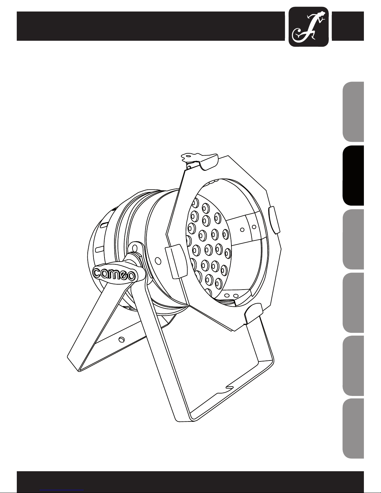
PAR 64 CAN
36 X 3W LED PAR CAN RGB CLP64RGB3W
3
ITALIANO
POLSKI
ESPAÑOL
FRANCAIS
FRANCAIS
FRANCAIS
FRANCAIS
FRANCAIS
DEUTSCH
ENGLISH

4
ENGLISHDEUTSCHFRANCAIS
FRANCAISFRANCAIS
FRANCAISFRANCAIS
ESPAÑOLPOLSKIITALIANO
PREVENTIVE MEASURES:
1. Please read this information carefully.
2. Keep all information and instructions in a safe place.
3. Please follow the instructions.
4. Please observe all warnings. Don‘t remove safety instructions or any other information located on the device.
5. Use the device only in the intended manner.
6. Use only stable and appropriate stands and/or mounts when the device is permanently installed. Make certain
that wall brackets are firmly secured. Make certain that the unit is installed securely and cannot fall down.
7. When installing please observe the corresponding safety standards for your country.
8. Do not install the device near radiators, heat accumulators, ovens or other sources of heat. Make certain that
the device is always installed so that is cooled sufficiently and cannot overheat.
9. Do not place open sources of ignition, e.g., burning candles, on the device.
10. Do not cover ventilation slots.
11. Do not operate the device in the immediate vicinity of water. Do not expose this equipment to combustible
materials, liquids or gases.
12. Please make certain that dripping or splashing water cannot get inside the device. Do not put objects filled
with fluids, such as vases or drinking vessels, on top of the device.
13. Make certain that objects cannot fall into the device.
14. Use the device only with accessories with which the manufacturer intends the device to be used.
15. CAUTION: If this device has a mains connector equipped with protective earth, it must be connected to a
mains socket with a protective ground connection. Never disable the function of the protective ground connection
of the included power cord.
16. Do not turn on the device immediately if it was exposed to strong temperature fluctuations (for example after
transportation). Moisture and condensation may damage the device. Leave the device switched off until it has
reached room temperature.
17. Do not open the device and do not make any changes to the device.
18. Before connecting to mains power, make certain that the mains voltage and the mains frequency are the
same as the operating values of the device (see type label). If the device is equipped with a supply voltage selector switch, make certain that the values of the device match the values of the mains power before connecting.
If the plug on the included cord does not fit your mains outlet, contact your electrician.
19. Make certain that the power cord is not stepped on. Protect the power cord against pinching, especially at
the device plug and the power plug.
20. In order to prevent damage or accidents, for example, due to tripping hazards, check all connections once
you have connected the device.
21. When connecting the device, make certain that the power plug remains readily accessible.
Always pull out the power plug when the device is not in use or when you clean the device. Disconnect the
power cord by pulling the plug not the cable.
22. Avoid switching the device on and off at short intervals, because it may shorten the durability of the device.
23. IMPORTANT: Replace fuse only by fuse of same type and rating! If fuse blows repeatedly please contact
authorized service center!
24. In order to disconnect the device completely from the mains voltage, the power plug must be unplugged.
25. If your device is equipped with a Volex power connector, the matching Volex device plug must be unlocked
in order to disconnect it. This also means that a tug on the power cord can pull the device out of place, thus
causing personal injuries and/or property damage. Thus please make certain to route your cables carefully.
5
ITALIANO
POLSKI
ESPAÑOL
FRANCAIS
FRANCAIS
FRANCAIS
FRANCAIS
FRANCAIS
DEUTSCH
ENGLISH
26. If there is a risk of lightning strike or during extended periods of disuse, unplug the power plug.
27. During transport, make certain that the equipment being transported cannot fall down and possibly
cause personal injuries and/or property damage.
28. If your device no longer works properly, if it has been exposed to liquids or an object has fallen inside it or
if it has been damaged in some other manner, turn the device off immediately und unplug the power plug. This
device should be repaired only by authorized experts.
29. Use only a dry cloth to clean the device.
30. Comply with all of the disposal laws that are applicable in your country. During disposal, please separate
plastic and paper/cardboard.
31. Plastic bags must be kept out of the reach of children.
OPERATING DETERMINATIONS
If this equipment is operated in any other way, than those described in this manual, the product may suffer
damage and the warranty becomes void.
Incorrect operation may lead to danger e.g.: short-circuit, burns, electric shocks, lamp failure etc.
Do not endanger your own safety and the safety of others!
Incorrect installation or use can cause serious damage to people and property.
WARNING!
1. Do not look into the beam from a distance of less than 40 cm (16 inches).
2. Do not stare into the beam for extended periods at a short distance.
3. Do not view the beam directly with optical instruments such as magnifiers.
CAUTION:
To reduce the risk of electric shock, do not remove cover (or back). No user serviceable parts inside. Refer
servicing to qualified personnel.
The lightning flash with arrowhead symbol within an equilateral triangle is intended to alert the user
to the presence of uninsulated “dangerous voltage” within the product´s enclosure that may be of
sufficient magnitude to constitute a risk to persons.
The exclamation mark within an equilateral triangle is intended to alert the user to the presence of
important operating and maintenance (servicing) instructions in the literature accompanying the
appliance.
CAUTION
RISK OF ELECTRIC SHOCK
DO NOT OPEN
INTRODUCTION:
CONTROL FEATURES
PAR 64 CAN
(CLP64RGB3WPS - polished
CLP64RGB3WBS - black)
• 4/6-channel DMX
• Individual control of Red, Green and Blue colour
FEATURES
• 36 colour LEDs (R12, G12, B12)
• Ultra Bright icker free 3W LEDs
• Sound control via internal microphone
• Colour jumping/fading speed and strobe effect
adjustable via control panel
• Multi-colour changes
• Master/Slave functions
• Rugged compact housing
• Double bracket
• Power consumption: 150 W
• Long life LEDs
OPERATING INSTRUCTIONS
The Cameo LED CAN is a DMX-512 controllable, colour mixing spot made up of high efciency and super bright
LED’s. There are three colours (red, green and blue) whose intensity can be controlled individually allowing the
creation of an unlimited range of colours. The Cameo LED light will operate in Stand-alone, Master/Slave, Sound
activated and via DMX-512 control.
6
ENGLISHDEUTSCHFRANCAIS
FRANCAISFRANCAIS
FRANCAISFRANCAIS
ESPAÑOLPOLSKIITALIANO
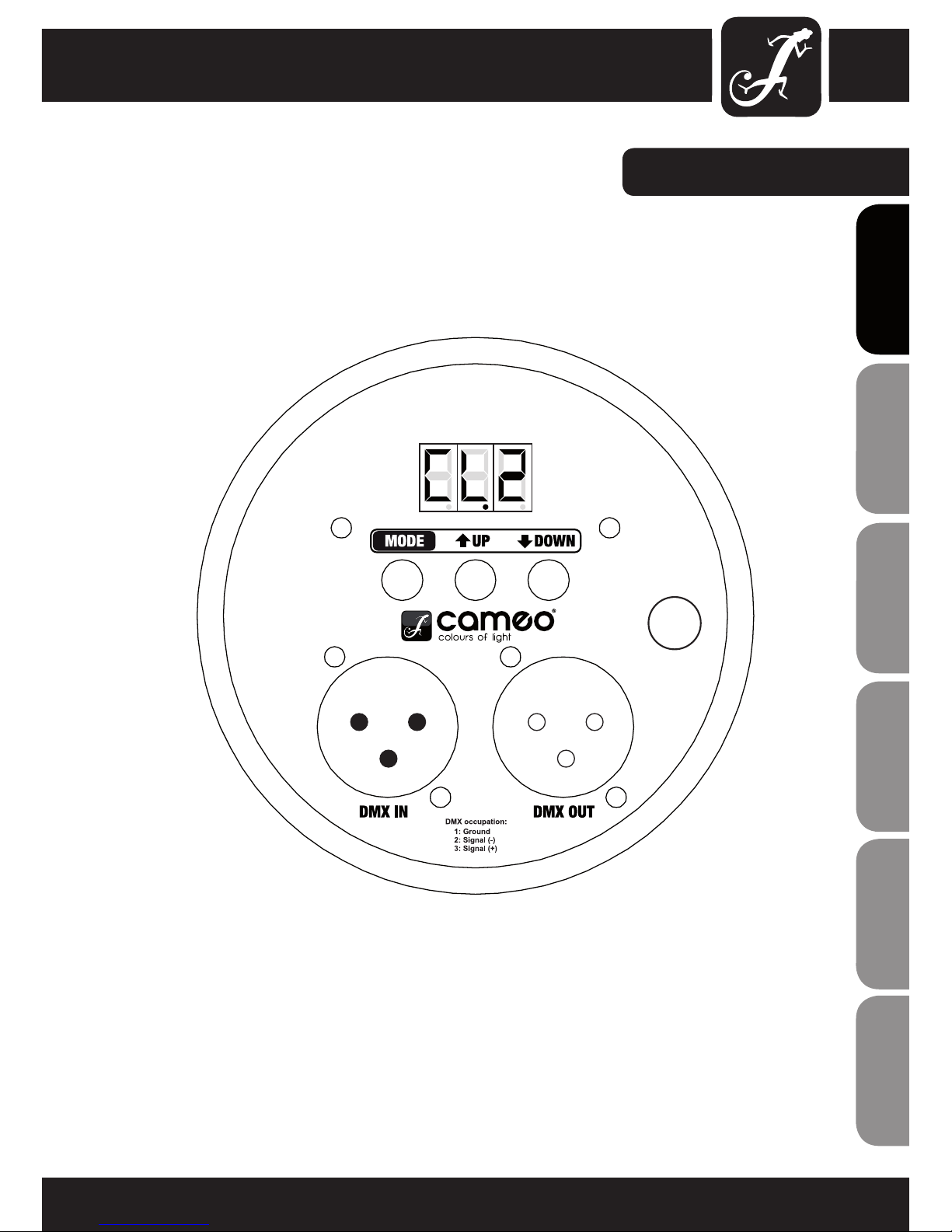
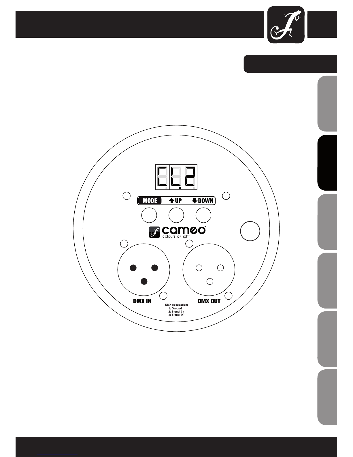
BACK PANEL:
7
ITALIANO
POLSKI
ESPAÑOL
FRANCAIS
FRANCAIS
FRANCAIS
FRANCAIS
FRANCAIS
DEUTSCH
ENGLISH
FUSE
F2A/250V
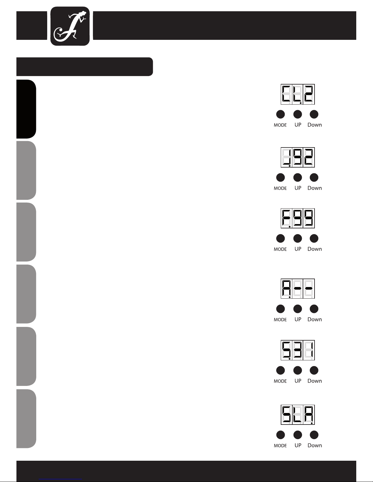
MODE SELECTION:
STATIC COLOUR MODE:
Press the MODE button repeatedly if necessary to select the Static Colour Mode. Press the
UP and DOWN buttons to select one of the 7 desired colours.
CL1 = Red, CL2 = Green, CL3 = Blue, CL4 = Yellow, CL5 = Cyan, CL6 = Purple, CL7 =
White (CL0 = blackout).
COLOUR JUMPING MODE
Press the MODE button repeatedly if necessary to select the Colour Jumping Mode. Press the
UP and DOWN buttons to select the colour jumping speed from J01 - J99.
COLOUR FADING MODE
Press the MODE button repeatedly if necessary to select the Colour Fading Mode. Press
the UP and DOWN buttons to select the fading speed from F01 -F99.
AUTO MODE
Press the MODE button repeatedly if necessary to select the Auto Mode. The unit changes
between Colour Jumping Mode and Colour Fading Mode automatically. The colour jumping
and fading speed can be preadjusted by using the speed settings of the Colour Jumping
and Colour Fading Modes.
SOUND ACTIVE MODE
Press the MODE button repeatedly if necessary to select the Sound Control Mode. The
unit will follow the beat of the music thanks to the built in microphone. Press the UP and
DOWN buttons to adjust the sensitivity of the microphone (S00 = least sensitiv / S31 =
most sensitiv).
MASTER/SLAVE MODE
Press the MODE button repeatedly if necessary to enter the Slave Mode.
Link slave units and the master unit (exclusively standalone modes) via DMX cables. The
slave unit will follow in sequence with the master unit.
8
ENGLISHDEUTSCHFRANCAIS
FRANCAISFRANCAIS
FRANCAISFRANCAIS
ESPAÑOLPOLSKIITALIANO
Programmes
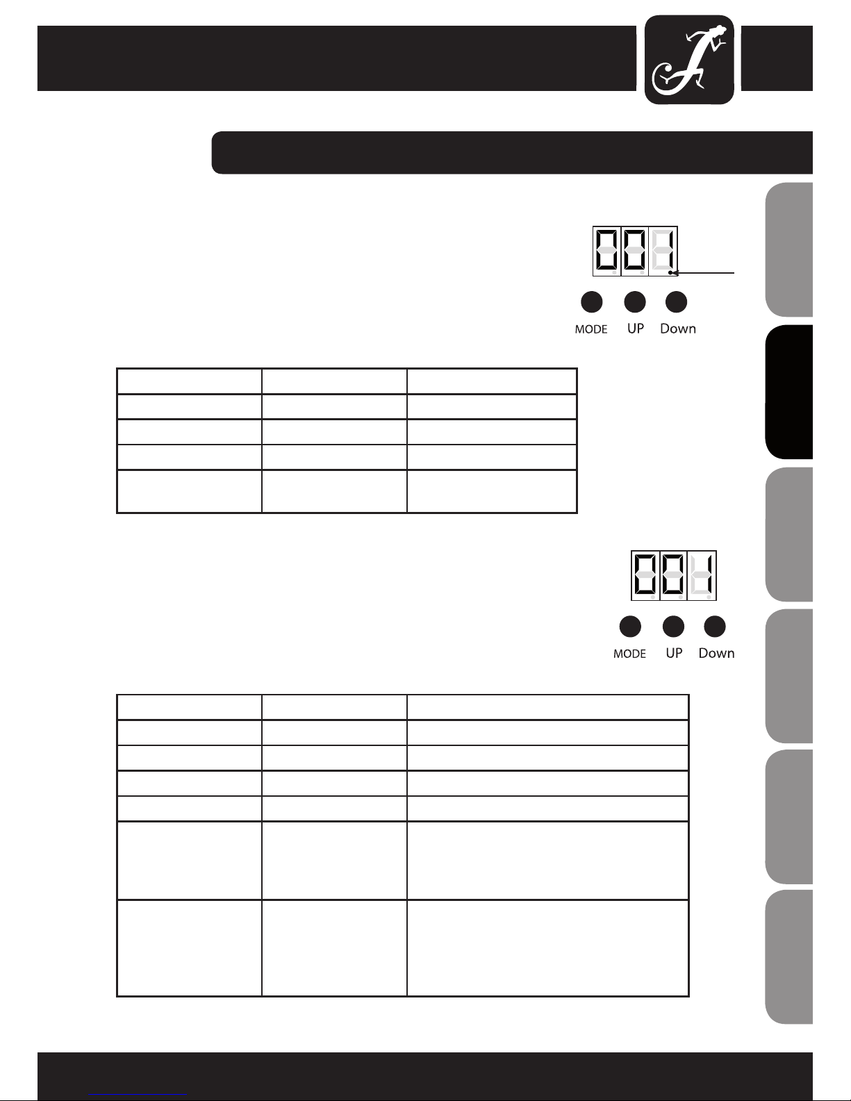
MODE SELECTION / DMX CONTROL MODE:
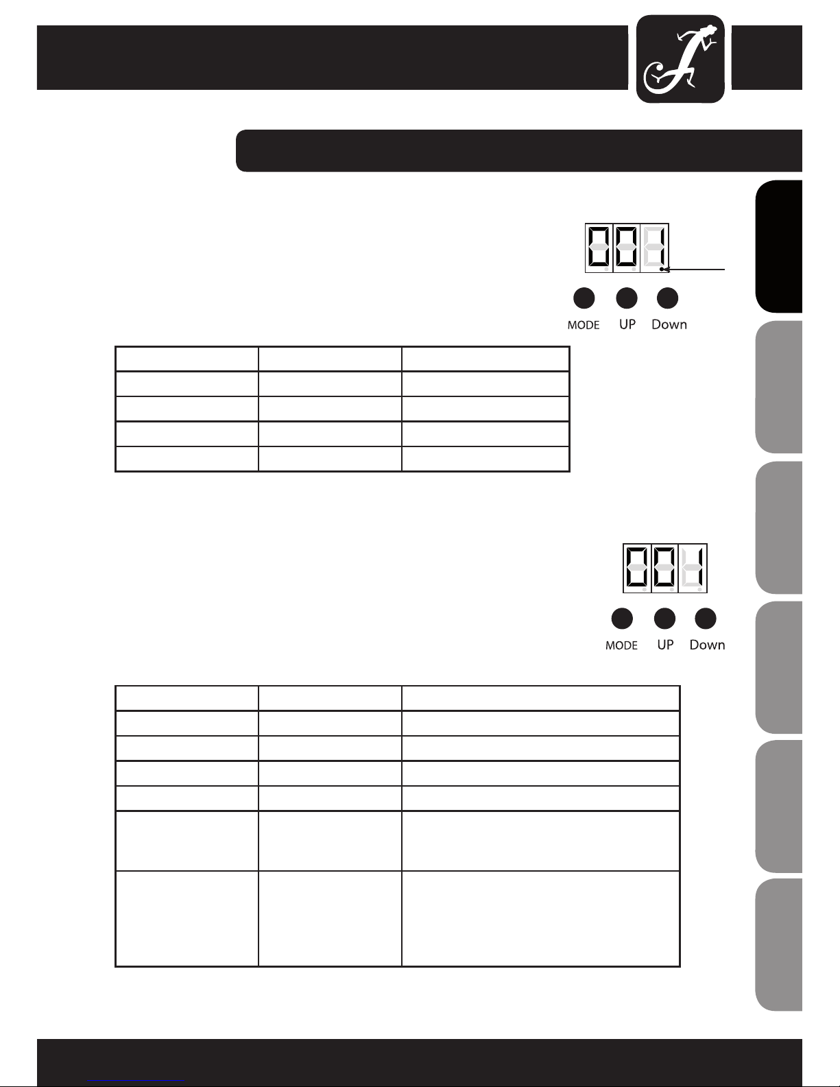
6 CHANNEL DMX MODE
To access the 6 Channel mode, press the MODE button to show NO red dot
under the rst digit of the DMX address. The unit is now ready for use in 6
channel mode. Select the desired DMX start address by using the UP and DOWN
buttons (001 - 512).
CHANNEL VALUE FUNCTION
CH1 000-255 RED (0-100%)
CH2 000-255 GREEN (0-100%)
CH3 000-255 BLUE (0-100%)
CH4 000-255 MASTER DIMMER (0-100%)
CH5 000-016
017-255
No function
Strobe speed - Jumping/Fading speed - Micro-
phone sensitivity (refers to channel 6)
CH6 000-031
032-095
096-159
160-223
224-255
No function
Colour fading
Colour jumping RGB
Colour jumping 7 colour
Sound control
4 CHANNEL DMX MODE
This Cameo PAR 64 CAN has two DMX modes to choose from, 4 channel or 6
channel. To access the 4 Channel mode, press the MODE button to show a red
dot illuminated under the third digit of the DMX address. The unit is now ready
for use in 4 channel mode. Select the desired DMX start address by using the
UP and DOWN buttons (001 - 512).
CHANNEL VALUE FUNCTION
CH1 000-255 RED (0-100%)
CH2 000-255 GREEN (0-100%)
CH3 000-255 BLUE (0-100%)
CH4 000-255 MASTER DIMMER (0-100%)
9
ITALIANO
POLSKI
ESPAÑOL
FRANCAIS
FRANCAIS
FRANCAIS
FRANCAIS
FRANCAIS
DEUTSCH
ENGLISH
Red Dot

DMX LINKING:
DMX-512
DMX (Digital Multiplex) is a universal protocol used as a form of communication between intelligent xtures
and controllers. A DMX controller sends DMX data instructions from the controller to the xture. DMX data
are sent as serial data that travel from xture to xture via the “DMX IN“ and “DMX OUT” XLR terminals
located on all DMX xtures (most controllers only have a “DMX OUT” terminal).
10
ENGLISHDEUTSCHFRANCAIS
FRANCAISFRANCAIS
FRANCAISFRANCAIS
ESPAÑOLPOLSKIITALIANO
DMX LINKING:
DMX is a language allowing all makes and models of different manufactures to be linked together and operate from a single controller, as long as all xtures and the controller are DMX compliant. To ensure proper
DMX data transmission, when using several DMX xtures try to use the shortest cable path possible. The
order in which xtures are connected in a DMX line does not inuence the DMX addressing. For example a
xture assigned to a DMX address of 1 may be placed anywhere in a DMX line, at the beginning, at the end,
or anywhere in the middle. When a xture is assigned a DMX address of 1, the DMX controller knows to
send DATA assigned to address 1 to that unit, no matter where it is located in the DMX chain.
Please check out our comprehensive DMX cable choices out of our Adam Hall product lines 3 STAR, 4 STAR
and 5 STAR
Keep in mind that DMX connections must be daisy chained. To avoid malfunction, DMX cabling should not
be divided in several lines without the use of an active splitter.
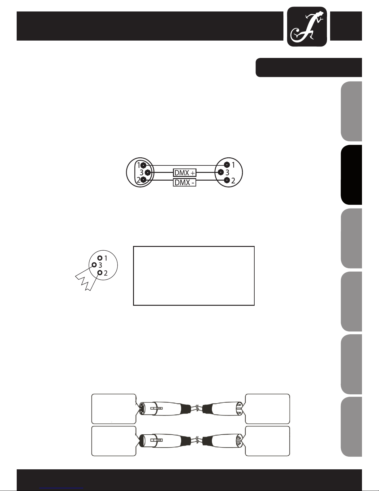
DMX CABLES:
11
ITALIANO
POLSKI
ESPAÑOL
FRANCAIS
FRANCAIS
FRANCAIS
FRANCAIS
FRANCAIS
DEUTSCH
ENGLISH
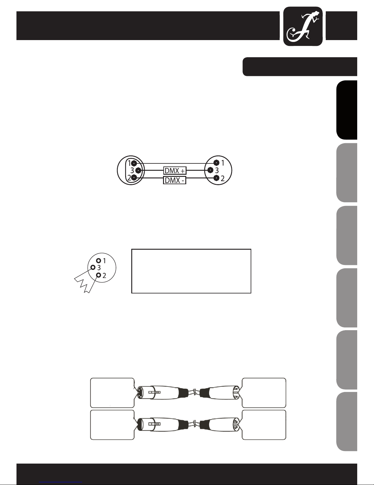
NOTICE:
• Be sure to follow gures 2 & 3 when making your own cables. Do not connect the cable’s shield conductor to
the ground lug or allow the shield conductor to come in contact with the XLR’s outer casing. Grounding the shield
could cause a short circuit and erratic behaviour.
SPECIAL NOTE: LINE TERMINATION:
• When longer runs of cable are used, you may need to use a terminator on the last unit to avoid erratic behaviour.
Using a cable terminator (Art. No. K3DMXT3) will decrease the possibilities of erratic behaviour.
• Some manufactures use 5-pin XLR connectors for data transmission in place of 3-pin. 5-Pin XLR xtures may
be implemented in a 3-pin XLR DMX line. When inserting standard 5-pin XLR connectors in to a 3-pin line a cable
adaptor must be used. The chart below details the correct cable conversion.
Termination reduces signal transmission problems and interference. It is always advisable to
connect a DMX terminator, (resistance 120 Ohm
1/4 W) between pin 2 (DMX-) and pin 3 (DMX+)
of the last fixture.
common
DMX-512 out
3-pin XLR
DMX-512 in
3-pin XLR
5-Pin XLR (socket)
Pin 1: GND (screen)
Pin 2: Signal (-)
Pin 3: Signal (+)
Pin 4: N/C
Pin 5: N/C
5-Pin XLR (socket)
Pin 1: GND (screen)
Pin 2: Signal (-)
Pin 3: Signal (+)
Pin 4: N/C
Pin 5: N/C
3-Pin XLR (socket)
Pin 1: GND (screen)
Pin 2: Signal (-)
Pin 3: Signal (+)
3-Pin XLR (socket)
Pin 1: GND (screen)
Pin 2: Signal (-)
Pin 3: Signal (+)

SPECIFICATIONS:
CLP 64 WEIGHT & DIMENSIONS (WITHOUT BRACKET)
Length 305 mm
Width 260 mm
Height 270 mm
Weight 3.4 kg
Beam angle 30 °
POWER
Power consumption 150 W
AC input 100 V AC - 250 V AC / 50 Hz / 60 Hz
FUSE
Main F1A for 120V / F2A for 250V
CONTROL & PROGRAMMING
Data input Locking 3-pin XLR male socket
Data output 3-pin XLR female socket
Protocols DMX-512 USITT
DMX modes 4-channel / 6-channel
12
ENGLISHDEUTSCHFRANCAIS
FRANCAISFRANCAIS
FRANCAISFRANCAIS
ESPAÑOLPOLSKIITALIANO
13
ITALIANO
POLSKI
ESPAÑOL
FRANCAIS
FRANCAIS
FRANCAIS
FRANCAIS
FRANCAIS
DEUTSCH
ENGLISH
LIMITED WARRANTY
This Limited Warranty applies to the Adam Hall, LD Systems, Defender, Palmer, Cameo and Eminence branded
products.
The statutory warranty rights towards the seller are not affected by this guarantee. In fact, it justifies, additional
independent warranty claims towards Adam Hall.
Adam Hall warrants that the Adam Hall product you have purchased from Adam Hall or from an Adam Hall authorized reseller is free from defects in materials or workmanship under normal use for a period of 2 or 5 years from
the date of purchase.
The Limited Warranty Period starts on the date of purchase. In order to receive warranty services you are required
to provide proof of the purchase date. Your dated sales or delivery receipt, showing the date of purchase, is your
proof of the purchase date. Should products of the brands named above be in need of repair within the limited warranty period, you are entitled to warranty services according to the terms and conditions stated in this document.
This Limited Warranty extends only to the original purchaser of this Adam Hall branded product and is not transferable to anyone who obtains ownership of the Adam Hall branded product from the original purchaser. During
the Limited Warranty Period, Adam Hall will repair or replace the defective component parts or the product. All
component parts or hardware products removed under this Limited Warranty become the property of Adam Hall.
In the unlikely event that your Adam Hall product has a recurring failure, Adam Hall, at its discretion, may elect to
provide you with a replacement unit of Adam Hall´s choice that is at least equivalent to your Adam Hall branded
product in hardware performance.
Adam Hall does not warrant that the operation of this product will be uninterrupted or error-free. Adam Hall is not
responsible for damage that occurs as a result of your failure to follow the instructions included with the Adam
Hall branded product.
This Limited Warranty does not apply,
- to wear parts (e.g. accumulator)
- to any product from which the serial number has been removed or that has been damaged or rendered defective as the result of an accident
- in case of, misuse, abuse, or other external causes
- by operation outside the usage parameters stated in the user´s documentation shipped with the product by use
of spare parts not manufactured or sold by Adam Hall
- by modication or service by anyone other than Adam Hall
These terms and conditions constitute the complete and exclusive warranty agreement between you and Adam
Hall regarding the Adam Hall branded product you have purchased.
MANUFACTURER´S DECLARATIONS:

14
ENGLISHDEUTSCHFRANCAIS
FRANCAISFRANCAIS
FRANCAISFRANCAIS
ESPAÑOLPOLSKIITALIANO
LIMITATION OF LIABILITY
If your Adam Hall branded hardware product fails to work as warranted above, your sole and exclusive remedy
shall be repair or replacement. Adam Halls’ maximum liability under this limited warranty is expressly limited
to the lesser of the price you have paid for the product or the cost of repair or replacement of any hardware
components that malfunction in conditions of normal use.
Adam Hall is not liable for any damages caused by the product or the failure of the product, including any lost
prots or savings or special, incidental, or consequential damages. Adam Hall is not liable for any claim made by
a third party or made by you for a third party.
This limitation of liability applies whether damages are sought, or claims are made, under this Limited Warranty
or as a tort claim (including negligence and strict product liability), a contract claim, or any other claim. This limitation of liability cannot be waived or amended by any person. This limitation of liability will be effective even if
you have advised Adam Hall of an authorized representative of Adam Hall of the possibility of any such damages.
This limitation of liability however, will not apply to claims for personal injury.
This Limited Warranty gives you specic legal rights. You may also have other rights that may vary from state to
state or from country to country. You are advised to consult applicable state or country laws for a full determina-
tion of your rights.
REQUESTING WARRANTY-SERVICE
To request warranty service for the product, contact Adam Hall or the Adam Hall authorized reseller from which
you purchased the product.
EC DECLARATION OF CONFORMITY
These devices meet the essential requirements and further relevant specications of Directives 2004/108/EC
(EMC) and 2006/95/EC (LVD). For more information, see www.adamhall.com.
CORRECT DISPOSAL OF THIS PRODUCT (ELECTRICAL WASTE)
(Applicable in the European Union and other European countries with separate collection systems)
This marking shown on the product or its literature, indicates that it should not be disposed with other household
wastes at the end of its working life. To prevent possible harm to the environment or human health from uncontrolled waste disposal, please separate this from other types of wastes and recycle it responsibly to promote the
sustainable reuse of material resources.
Household users should contact either the retailer where they purchased this product, or their local government
office, for details on where and how they can recycle this item in an enviromentally friendly manner.
Business users should contact their supplier and check the terms and conditions of the purchase contract. This
product should not be mixed with other commercial wastes for disposal.
MANUFACTURER´S DECLARATIONS:

15
ITALIANO
POLSKI
ESPAÑOL
FRANCAIS
FRANCAIS
FRANCAIS
FRANCAIS
FRANCAIS
DEUTSCH
ENGLISH
MANUFACTURER´S DECLARATIONS:
WEEE-DECLARATION
Your LD-Systems product was developed and manufactured with high quality materials and components wich can
be recycled and/or reused. This symbol indicates that electrical and electronic equipment must be disposed of
separately from normal waste at the end of its operational lifetime.
Please dispose of this product by bringing it to your local collection point or recycling centre for such equipment.
This will help to protect the environment in which we all live.
BATTERIES AND ACCUMULATORS
The supplied batteries or rechargeable batteries can be recycled. Please dispose of them as special waste or return
them to your specialist dealer. In order to protect the environment, only dispose exhausted batteries.
ECOLOGY AND ENERGY SAVING
Saving electric energy helps to protect the environment. Please turn off all electrical equipment when it is not in
use. To avoid power consumption in idle mode, disconnect all electrical equipment from mains when not in use.
Adam Hall GmbH, all rights reserved. The technical data and the functional product characteristics can be subject to
modifications. The photocopying, the translation, and all other forms of copying of fragments or of the integrality of
this user’s manual is prohibited.

ENGLISHDEUTSCHFRANCAIS
FRANCAISFRANCAIS
FRANCAISFRANCAIS
ESPAÑOLPOLSKIITALIANO
16
Wir freuen uns, dass Sie sich für ein Produkt von Cameo Light entschieden haben!
Dieses Gerät wurde unter hohen Qualitätsanforderungen entwickelt und gefertigt, um viele Jahre einen reibungslosen Betrieb zu gewährleisten.
Bitte lesen Sie diese Bedienungsanleitung sorgfältig, damit Sie Ihren neuen Scheinwerfer von Cameo Light
schnell optimal einsetzen können.
Weitere Informationen über Cameo Light erhalten Sie auf unserer Website WWW.CAMEOLIGHT.COM.
PAR 64 CAN
36 X 3 W LED RGB PAR SCHEINWERFER CLP64RGB3W
ITALIANO
POLSKI
ESPAÑOL
FRANCAIS
FRANCAIS
FRANCAIS
FRANCAIS
FRANCAIS
DEUTSCH
ENGLISH
17

ENGLISHDEUTSCHFRANCAIS
FRANCAISFRANCAIS
FRANCAISFRANCAIS
ESPAÑOLPOLSKIITALIANO
18
SICHERHEITSHINWEISE:
1. Lesen Sie diese Anleitung bitte sorgfältig durch.
2. Bewahren Sie alle Informationen und Anleitungen an einem sicheren Ort auf.
3. Befolgen Sie die Anweisungen.
4. Beachten Sie alle Warnhinweise. Entfernen Sie keine Sicherheitshinweise oder andere Informationen vom
Gerät.
5. Verwenden Sie das Gerät nur in der vorgesehenen Art und Weise.
6. Verwenden Sie ausschließlich stabile und passende Stative bzw. Befestigungen (bei Festinstallationen). Stellen
Sie sicher, dass Wandhalterungen ordnungsgemäß installiert und gesichert sind. Stellen Sie sicher, dass das
Gerät sicher installiert ist und nicht herunterfallen kann.
7. Beachten Sie bei der Installation die für Ihr Land geltenden Sicherheitsvorschriften.
8. Installieren und betreiben Sie das Gerät nicht in der Nähe von Heizkörpern, Wärmespeichern, Öfen oder
sonstigen Wärmequellen. Sorgen Sie dafür, dass das Gerät immer so installiert ist, dass es ausreichend gekühlt
wird und nicht überhitzen kann.
9. Platzieren Sie keine Zündquellen wie z. B brennende Kerzen auf dem Gerät.
10. Die Lüftungsschlitze dürfen nicht blockiert werden
11. Betreiben Sie das Gerät nicht in unmittelbarer Nähe von Wasser. Bringen Sie das Gerät nicht mit brennbaren
Materialien, Flüssigkeiten oder Gasen in Berührung.
12. Sorgen Sie dafür, dass kein Tropf- oder Spritzwasser in das Gerät eindringt. Stellen Sie keine mit Flüssigkeit
gefüllten Behältnisse wie Vasen oder Trinkgefäße auf das Gerät.
13. Sorgen Sie dafür, dass keine Gegenstände in das Gerät fallen können.
14. Betreiben Sie das Gerät nur mit dem vom Hersteller empfohlenen und vorgesehenen Zubehör.
15. ACHTUNG: Wenn das Stromkabel des Geräts mit einem Schutzkontakt ausgestattet ist, muss es an einer
Steckdose mit Schutzleiter angeschlossen werden. Deaktivieren Sie niemals den Schutzleiter des mitgelieferten
Kaltgerätekabels.
16. Schalten Sie das Gerät nicht sofort ein, wenn es starken Temperaturschwankungen ausgesetzt war (beispielsweise nach dem Transport). Feuchtigkeit und Kondensat könnten das Gerät beschädigen. Schalten Sie das
Gerät erst ein, wenn es Zimmertemperatur erreicht hat.
17. Öffnen Sie das Gerät nicht und verändern Sie es nicht.
18. Bevor Sie das Gerät an die Steckdose anschließen, prüfen Sie zuerst, ob die Spannung und die Frequenz
des Stromnetzes mit den auf dem Gerät angegebenen Werten übereinstimmen. Verfügt das Gerät über einen
Spannungswahlschalter, schließen Sie das Gerät nur an die Steckdose an, wenn die Gerätewerte mit den Werten
des Stromnetzes übereinstimmen.
Wenn das mitgelieferte Netzkabel nicht in Ihre Netzsteckdose passt, wenden Sie sich an Ihren Elektriker.
19. Treten Sie nicht auf das Kaltgerätekabel. Sorgen Sie dafür, dass das Kaltgerätekabel speziell an der Netz- und
der Gerätebuchse nicht geknickt wird.
20. Überprüfen Sie nach dem Anschluss des Geräts alle Kabelwege, um Schäden oder Unfälle, z. B. durch
Stolperfallen zu vermeiden.
21. Achten Sie bei der Verkabelung des Geräts immer darauf, dass das Netzkabel stets frei zugänglich ist.
Ziehen Sie immer den Netzstecker, wenn das Gerät nicht benutzt wird, oder Sie das Gerät reinigen möchten.
Ziehen Sie das Kaltgerätekabel immer am Stecker und nicht am Kabel aus der Steckdose.
22. Schalten Sie das Gerät möglichst nicht schnell hintereinander ein und aus, da sonst die Lebensdauer des
Geräts beeinträchtigt werden könnte.
23. WICHTIGER HINWEIS: Ersetzen Sie die Sicherung ausschließlich durch eine Sicherung des gleichen Typs
ITALIANO
POLSKI
ESPAÑOL
FRANCAIS
FRANCAIS
FRANCAIS
FRANCAIS
FRANCAIS
DEUTSCH
ENGLISH
19
und mit gleichen Werten. Sollte die Sicherung wiederholt auslösen, wenden Sie sich bitte an ein autorisiertes
Servicezentrum.
24. Um das Gerät vollständig vom Stromnetz zu trennen, entfernen Sie das Netzkabel.
25. Wenn Ihr Gerät mit einem Volex-Netzanschluss bestückt ist, muss der passende Volex-Gerätestecker
entsperrt werden, bevor er entfernt werden kann. Das bedeutet aber auch, dass das Gerät durch eine Ziehen
am Kaltgerätekabel verrutschen kann, wodurch Personen verletzt werden und/oder andere Schäden auftreten
können. Verlegen Sie Ihre Kabel daher immer sorgfältig.
26. Entfernen Sie das Netzkabel bei Gefahr eines Blitzschlags oder wenn Sie das Gerät länger nicht verwenden.
27. Achten Sie beim Transport darauf, dass das Gerät nicht herunterfallen und dabei möglicherweise Sach- und
Personenschäden verursachen kann.
28. Wenn Ihr Gerät nicht mehr ordnungsgemäß funktioniert, Flüssigkeiten oder Gegenstände in das Geräteinnere gelangt sind oder das Gerät anderweitig beschädigt wurde, schalten Sie es sofort aus und ziehen Sie den
Stecker. Dieses Gerät darf nur von autorisiertem Fachpersonal repariert werden.
29. Verwenden Sie zur Reinigung des Geräts ein trockenes Tuch.
30. Beachten Sie alle in Ihrem Land geltenden Entsorgungsgesetze. Trennen Sie bei der Entsorgung bitte Kunststoff und Papier bzw. Kartonagen voneinander.
31. Kunststoffbeutel müssen außer Reichweite von Kindern aufbewahrt werden.
CAUTION
RISK OF ELECTRIC SHOCK
DO NOT OPEN
ACHTUNG:
Entfernen Sie niemals die Abdeckung, da sonst das Risiko eines elektrischen Schlages besteht. Im Inneren des
Geräts befinden sich keine Teile, die vom Bediener repariert oder gewartet werden können. Lassen Sie Reparaturen ausschließlich von qualifiziertem Service-Personal durchführen.
Das gleichschenkelige Dreieck mit dem Blitzsymbol kennzeichnet
nicht-isolierte, „gefährliche“ Spannungen im Gerät,
die einen für die Gesundheit gefährlichen Stromschlag verursachen können.
Das gleichschenkelige Dreieck mit dem Ausrufezeichen kennzeichnet wichtige Bedienungs- und
Wartungshinweise.
EINFÜHRUNG:
STEUERUNGSFUNKTIONEN
PAR 64 CAN
(CLP64RGB3WPS - poliert
CLP64RGB3WBS - schwarz)
• 4-/6-Kanal-DMX-Steuerung
• Rot, Grün und Blau individuell steuerbar
FEATURES
• 36 Farb-LEDs (R12, G12, B12)
• Ultra-leuchtstarke, ackerfreie LEDs (3W)
• Musiksteuerung über eingebautes Mikrofon
• Farbwechsel-/Überblendgeschwindigkeit und Stro-
boskopeffekt über Bedienpanel steuerbar
• Multicolor-Farbwechsel
• Master/Slave-Funktionalität
• Robustes, kompaktes Gehäuse
• Doppelhalterung
• Leistungsaufnahme: 150 W
• Longlife-LEDs mit besonders langer Lebensdauer
BEDIENUNG
Der Cameo LED CAN ist ein über DMX-512 steuerbarer, hochefzienter Farbscheinwerfer mit ultrahellen LEDs.
Die Intensität der drei Farben (Rot, Grün und Blau) lässt sich einzeln steuern, wodurch unendlich viele verschiedene Farbnuancen ermöglicht werden. Der Cameo LED-Strahler lässt sich sowohl einzeln als auch im Master/
Slave-Betrieb, per Musiksteuerung und via DMX-512-Protokoll betreiben.
ENGLISHDEUTSCHFRANCAIS
FRANCAISFRANCAIS
FRANCAISFRANCAIS
ESPAÑOLPOLSKIITALIANO
20
RÜCKSEITE:
ITALIANO
POLSKI
ESPAÑOL
FRANCAIS
FRANCAIS
FRANCAIS
FRANCAIS
FRANCAIS
DEUTSCH
ENGLISH
21
FUSE
F2A/250V

MODUS AUSWÄHLEN:
STATISCHE FARBE:
Drücken Sie die MODE-Taste (falls erforderlich mehrmals) und wählen Sie die Betriebsart
„Statische Farbe“ aus. Wählen Sie anschließend mit den Tasten UP und DOWN eine der 7
Farben aus.
CL1 = Rot, CL2 = Grün, CL3 = Blau, CL4 = Gelb, CL5 = Cyan, CL6 = Lila, CL7 = Weiß (CL0
= Blackout)
FARBWECHSEL
Drücken Sie die MODE-Taste (falls erforderlich mehrmals) und wählen Sie die Betriebsart
„Farbwechsel“ aus. Stellen Sie anschließend mit den Tasten UP und DOWN die Farbwechselgeschwindigkeit (J01 - J99) ein.
ÜBERBLENDEN
Drücken Sie die MODE-Taste (falls erforderlich mehrmals) und wählen Sie die Betriebsart
„Überblenden“ aus. Stellen Sie anschließend mit den Tasten UP und DOWN die Überblendgeschwindigkeit (F01 -F99) ein.
AUTO-MODUS
Drücken Sie die MODE-Taste (falls erforderlich mehrmals) und wählen Sie den Auto-Modus
aus. In dieser Betriebsart wird automatisch zwischen Farbwechsel- und ÜberblendenModus gewechselt. Die Farbwechsel- bzw. Überblendgeschwindigkeit wird über die
Einstellungen des jeweiligen Modus festgelegt.
MUSIKSTEUERUNG
Drücken Sie die MODE-Taste (falls erforderlich mehrmals) und wählen Sie die Betriebsart
„Musiksteuerung“ aus. Nun wird die Lichtanlage über das eingebaute Mikrofon gesteuert
und folgt dem Takt der Musik. Stellen Sie mit den Tasten UP und DOWN die MikrofonEmpndlichkeit (S00 = geringste Empndlichkeit / S31 = höchste Empndlichkeit) ein.
MASTER/SLAVE-BETRIEB
Drücken Sie die MODE-Taste (falls erforderlich mehrmals) und wählen Sie den Slave-
Modus aus.
Verbinden Sie die Slave-Einheiten und die Master-Einheit (ausschließlich Standalone-Modi)
mit einem DMX-Kabel. Nun folgt die Slave-Einheit der Master-Einheit.
ENGLISHDEUTSCHFRANCAIS
FRANCAISFRANCAIS
FRANCAISFRANCAIS
ESPAÑOLPOLSKIITALIANO
22
Programmes
AUSWAHL BETRIEBSART / DMX- STEUERUNG:
6-KANAL-DMX-MODUS
Um den 6-Kanal-Betrieb zu aktivieren, drücken Sie die MODE-Taste, bis der rote
Punkt unterhalb der ersten Ziffer der DMX-Adresse NICHT mehr leuchtet. Nun
arbeitet der Scheinwerfer im 6-Kanal-Modus. Wählen Sie anschließend mit den
Tasten UP und DOWN die gewünschte DMX-Startadresse (001 - 512) aus.
KANAL WERT FUNKTION
CH1 000-255 ROT (0 - 100%)
CH2 000-255 GRÜN (0 - 100%)
CH3 000-255 BLAU (0 - 100%)
CH4 000-255 MASTER-DIMMER (0 - 100%)
CH5 000-016
017-255
Keine Funktion zugewiesen
Stroboskopgeschwindigkeit - Farbwechsel-/
Überblendgeschwindigkeit - Empndlichkeit des
Mikrofons (gilt für Kanal 6)
CH6 000-031
032-095
096-159
160-223
224-255
Keine Funktion zugewiesen
Überblenden
Farbwechsel RGB
Farbwechsel 7-Farben
Musiksteuerung
4-KANAL-DMX-MODUS
Der Cameo PAR 64 CAN bietet zwei verschiedene DMX-Betriebsarten: 4-Kanalund 6-Kanal-Betrieb. Um den 4-Kanal-Betrieb zu aktivieren, drücken Sie
die MODE-Taste, bis unterhalb der dritten Ziffer der DMX-Adresse ein roter
Punkt leuchtet. Nun arbeitet der Scheinwerfer im 4-Kanal-Modus. Wählen Sie
anschließend mit den Tasten UP und DOWN die gewünschte DMX-Startadresse
(001 - 512) aus.
KANAL WERT FUNKTION
CH1 000-255 ROT (0 - 100%)
CH2 000-255 GRÜN (0 - 100%)
CH3 000-255 BLAU (0 - 100%)
CH4 000-255 MASTER-DIMMER (0 -
100%)
ITALIANO
POLSKI
ESPAÑOL
FRANCAIS
FRANCAIS
FRANCAIS
FRANCAIS
FRANCAIS
DEUTSCH
ENGLISH
23
Red Dot

ENGLISHDEUTSCHFRANCAIS
FRANCAISFRANCAIS
FRANCAISFRANCAIS
ESPAÑOLPOLSKIITALIANO
24
DMX-512
DMX (Digital Multiplex) ist die Bezeichnung für ein universelles Übertragungsprotokoll für die Kommunikation zwischen entsprechenden Geräten und Controllern. Ein DMX-Controller sendet DMX-Daten an das/die
angeschlossene(n) DMX-Gerät(e). Die DMX-Datenübertragung erfolgt stets als serieller Datenstrom, der über die
an jedem DMX-fähigen Gerät vorhandenen „DMX IN“- und „DMX OUT“-Anschlüsse (XLR-Steckverbinder) von
einem angeschlossenen Gerät an das nächste weitergeleitet wird. (Die meisten Controller verfügen lediglich über
einen DMX-Ausgang.)
24
DMX-VERBINDUNG:
DMX-VERBINDUNG:
DMX ist die gemeinsame "Sprache", über die sich die unterschiedlichsten Gerätetypen und Modelle
verschiedener Hersteller miteinander verkoppeln und über einen zentralen Controller steuern lassen –
sofern sämtliche Geräte und der Controller DMX-kompatibel sind. Für eine optimale Datenübertragung
ist es erforderlich, die Verbindungskabel zwischen den einzelnen Geräten so kurz wie möglich zu halten.
Die Reihenfolge, in der die Geräte in das DMX-Netzwerk eingebunden sind, hat keinen Einfluss auf die
Addressierung. So kann sich das Gerät mit der DMX-Adresse 1 an einer beliebigen Position in der (seriellen)
DMX-Kette befinden, am Anfang, am Ende oder irgendwo in der Mitte. Wird einem Gerät die DMX-Adresse
1 zugewiesen, "weiß" der Controller, dass er alle der Adresse 1 zugeordneten Daten an dieses Gerät
senden soll – ungeachtet seiner Position im DMX-Verbund.
Eine umfangreiche Auswahl geeigneter Kabel finden Sie in den Adam Hall-Produktlinien 3 STAR, 4 STAR
und 5 STAR.
Bitte beachten Sie, dass DMX-Geräte grundsätzlich seriell verschaltet werden und die Verbindungen nicht
gesplittet werden können.
ITALIANO
POLSKI
ESPAÑOL
FRANCAIS
FRANCAIS
FRANCAIS
FRANCAIS
FRANCAIS
DEUTSCH
ENGLISH
2525
DMX-KABEL:
HINWEIS:
• Beachten Sie bei der Anfertigung eigener Kabel unbedingt die Abbildungen 2 und 3. Verbinden Sie auf
keinen Fall die Abschirmung des Kabels mit dem Massekontakt des Steckers, und achten Sie darauf, dass die
Abschirmung nicht mit dem XLR-Steckergehäuse in Kontakt kommt. Hat die Abschirmung Massekontakt, kann
dies zu Kurzschlüssen und Systemfehlern führen.
BITTE BEACHTEN SIE: LEITUNGSABSCHLUSS (TERMINIERUNG):
• Bei längeren Kabelstrecken kann es sein, dass das letzte Gerät in der Kette einen Abschlusswiderstand
benötigt, um Systemfehlern vorzubeugen.
Dies wird durch ein Kabel-Abschlussmodul (Art.-Nr. K3DMXT3) erreicht.
• Einige Hersteller verwenden für die Datenübertragung keine 3-Pol-XLR-Steckverbinder, sondern 5-PolVersionen. Geräte mit 5-Pol-XLR-Anschlüssen können jedoch auch in einen DMX-Verbund mit 3-Pol-XLRAnschlüssen integriert werden. In diesem Fall ist ein geeigneter Kabeladapter erforderlich. Die folgende
Abbildung zeigt die korrekte Belegung der entsprechenden Stecker.
Die Verwendung eines Abschlusswiderstands
(Terminierung) reduziert Interferenzen und
andere Probleme bei der Signalübertragung.
Es ist immer ratsam, ein DMX-Abschlussmodul
(Widerstand 120 Ohm, 1/4 W) zwischen Pol 2
(DMX-) und Pol 3 (DMX+) des letzten Geräts in
der Kette einzufügen.
Übliche Verbindung
DMX-512-Ausgang
3-Pol-XLR
DMX-512-Eingang
3-Pol-XLR
5-Pol-XLR (Buchse)
Pol 1: Erde
(Abschirmung)
Pol 2: Signal (-)
Pol 3: Signal (+)
Pol 4: nicht belegt
Pol 5: nicht belegt
5-Pol-XLR (Buchse)
Pol 1: Erde
(Abschirmung)
Pol 2: Signal (-)
Pol 3: Signal (+)
Pol 4: nicht belegt
Pol 5: nicht belegt
3-Pol-XLR (Buchse)
Pol 1: Erde
(Abschirmung)
Pol 2: Signal (-)
Pol 3: Signal (+)
3-Pol-XLR (Buchse)
Pol 1: Erde
(Abschirmung)
Pol 2: Signal (-)
Pol 3: Signal (+)
TECHNISCHE DATEN:
CLP 64 GEWICHT & ABMESSUNGEN (OHNE HALTERUNG)
Länge 305 mm
Breite 260 mm
Höhe 270 mm
Gewicht 3,4 kg
Abstrahlwinkel 30 °
POWER
Leistungsaufnahme 150 W
Stromversorgung 100 V AC - 250 V AC / 50 Hz - 60 Hz
SICHERUNG
Hauptsicherung F1A für 120 V / F2A für 250 V
STEUERUNG & PROGRAMMIERUNG
DMX-Eingang Verriegelbare XLR(m)-Buchse (3-Pol)
DMX-Ausgang XLR(f)-Buchse (3-Pol)
Protokolle DMX-512 USITT
DMX-Modi 4-Kanal / 6-Kanal
ENGLISHDEUTSCHFRANCAIS
FRANCAISFRANCAIS
FRANCAISFRANCAIS
ESPAÑOLPOLSKIITALIANO
26

ITALIANO
POLSKI
ESPAÑOL
FRANCAIS
FRANCAIS
FRANCAIS
FRANCAIS
FRANCAIS
DEUTSCH
ENGLISH
27
HERSTELLERERKLÄRUNGEN:
GARANTIEBESTIMMUNGEN
Diese Garantie erstreckt sich auf die Marken Adam Hall, LD Systems, LD Premium, Defender, Palmer, Cameo und
Eminence.
Die gesetzlichen Gewährleistungsrechte gegenüber dem Verkäufer werden von dieser Garantie nicht berührt. Vielmehr begründet diese Garantie zusätzliche selbständige Ansprüche gegenüber Adam Hall.
Mit dieser Garantie stellt Adam Hall sicher, dass das von Ihnen bei Adam Hall oder einem Adam Hall Partner
erworbene Produkt bei normalem Gebrauch während des Zeitraums von 2 bzw. 3 Jahren ab Kaufdatum frei von
Material- oder Verarbeitungsfehlern ist.
Der Garantiezeitraum beginnt mit dem Datum des Kaufs.
Der Geltendmachung eines Anspruchs auf Garantieleistungen erforderliche Nachweis des Kaufdatums, erfolgt
durch die mit dem Kaufdatum versehene Quittung oder den mit dem Kaufdatum versehenen Lieferschein. Sie haben Anspruch auf den Garantieservice zu den in diesem Dokument aufgeführten Bedingungen und Bestimmungen,
falls eine Reparatur der unter den oben genanten Marken vertriebenen Produkte innerhalb des Garantiezeitraums
erforderlich ist.
Diese Garantie gilt nur für den ursprünglichen Käufer des von Adam Hall vertriebenen Produkts und ist nicht an
Personen übertragbar, denen vom ursprünglichen Käufer das Eigentum am Adam Hall Produkt übertragen wird.
Innerhalb des Garantiezeitraums werden die fehlerhaften Komponenten oder das Produkt von Adam Hall repariert
oder ersetzt. Alle im Rahmen dieser Garantie entfernten Komponenten und Hardware-Produkte gehen in das Eigentum von Adam Hall über.
In dem unwahrscheinlichen Fall, dass bei dem von Ihnen erworbenen Adam Hall Produkt ein Fehler wiederholt auftritt, kann Adam Hall nach eigenem Ermessen entscheiden, Ihnen dieses Produkt durch ein vergleichbares Produkt
mit mindestens derselben Leistung zu ersetzen.
Adam Hall übernimmt keine Garantie für einen störungs- oder fehlerfreien Betrieb dieses Produkts. Adam Hall
übernimmt keine Verantwortung für auf eine inkorrekte Befolgung der im Lieferumfang des Adam Hall erhaltenen
Anweisungen zurückzuführende Schäden.
Diese Garantie erstreckt sich nicht auf:
- Verschleißteile (z.B. Akkumulator).
- Geräte deren Seriennummer entfernt wurde oder die beschädigt oder fehlerhaft wurden als folge eines Unfalls
- nicht sachgerechter oder missbräuchlicher Verwendung oder anderer missbräuchlicher Verwendung oder anderer äußerer Ursachen,
- Geräte die nicht entsprechend den Betriebsparametern betrieben wurden, die in den im Lieferumfang des Produkts enthaltenen Benutzerunterlagen festgelegt sind
- Geräte die aufgrund der Verwendung nicht von Adam Hall hergestellter oder vertriebener Teile repariert wurde
- Geräte die durch Änderung oder Wartung durch jemand anderen als Adam Hall getätigt wurde.
Diese Bestimmungen und Bedingungen stellen die vollständige und ausschließliche Garantievereinbarung zwischen Ihnen und Adam Hall für das von Ihnen erworbene Adam Hall Produkt dar.
 Loading...