

Cameo FLAT PAR CAN TRI 3W IR, FLAT PAR CAN RGB 10 IR, CLPFLAT1TRI3WIR, CLPFLAT1TRI5X3WIR, CLPFLAT1RGB10IR User Manual

FLAT PAR CAN TRI 3W IR
CLPFLAT1TRI3WIR
USER´S MANUAL
BEDIENUNGSANLEITUNG
MANUEL D´UTILISATION
MANUAL DE USUARIO
INSTRUKCJA OBSŁUGI
MANUALE D‘USO
FLAT PAR CAN RGB 10 IR
CLPFLAT1RGB10IR

2
Introduction
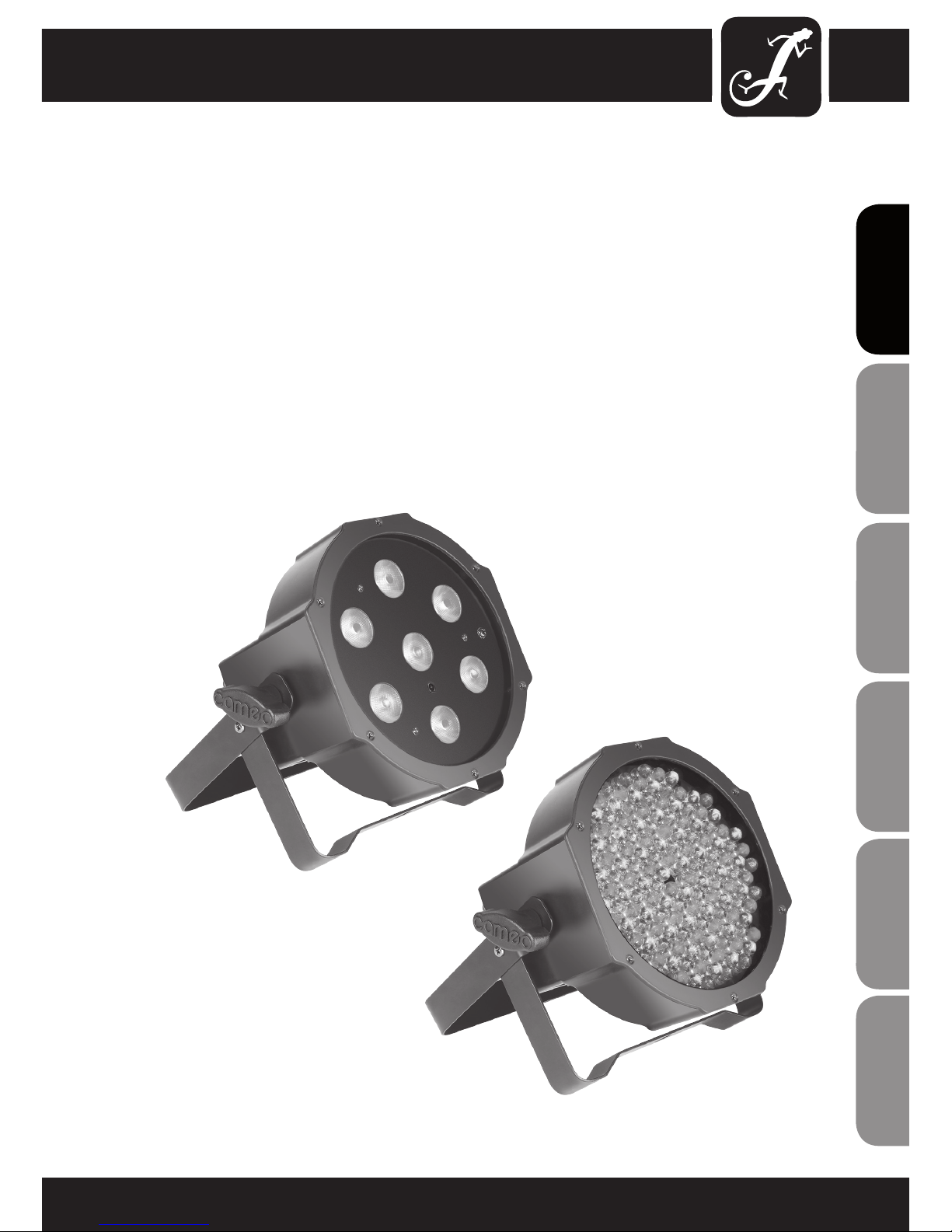
Cameo CLPFLAT1TRI3WIR and CLPFLAT1RGB10IR - bright, lightweight and compact!
Controllable via an infrared remote, the LED spotlights from Cameo are particularly flat, bright PAR projectors,
which cover the RGB spectrum. The light and compact ABS design with a dual bracket is suitable for flexible and
silent use; thanks to extremely low heat build-up, no fan is required.
ENGLISHDEUTSCHFRANCAIS
FRANCAISFRANCAIS FRANCAISFRANCAIS
ESpAñoLpoLSKIITALIANo
Thank you for choosing Cameo Lights!
We have designed this product to give you reliable operation over many years.
Please, take a few moments to read these instructions carefully, as we want you to enjoy your new Cameo Lights
products quickly and to the fullest.
Further information about Cameo Lights check our website WWW.CAMEOLIGHT.COM
3
ITALIANOPOLSKIESPAÑOL
FRANCAISFRANCAIS FRANCAISFRANCAIS
FRANCAISDEUTSCHENGLISH
FLAT PAR CAN TRI 3W IR
CLPFLAT1TRI3WIR
FLAT PAR CAN RGB 10 IR
CLPFLAT1RGB10IR

4
ENGLISHDEUTSCHFRANCAIS
FRANCAISFRANCAIS FRANCAISFRANCAIS
ESpAñoLpoLSKIITALIANo
PREVENTIVE MEASURES:
1. Please read these instructions carefully.
2. Keep all information and instructions in a safe place.
3. Follow the instructions.
4. Observe all safety warnings. Never remove safety warnings or other information from the equipment.
5. Use the equipment only in the intended manner and for the intended purpose.
6. Use only sufficiently stable and compatible stands and/or mounts (for fixed installations). Make certain that wall
mounts are properly installed and secured. Make certain that the equipment is installed securely and cannot fall down.
7. During installation, observ e the applicable safety regulations for your country.
8. Never install and operate the equipment near radiators, heat registers, ovens or other sources of heat. Make
certain that the equipment is always installed so that is cooled sufficiently and cannot overheat.
9. Never place sources of ignition, e.g., burning candles, on the equipment.
10. Ventilation slits must not be blocked.
11. Do not use this equipment in the immediate vicinity of water (does not apply to special outdoor equipment in this case, observe the special instructions noted below. Do not expose this equipment to flammable materials,
fluids or gases.
12. Make certain that dripping or splashed water cannot enter the equipment. Do not place containers filled with
liquids, such as vases or drinking vessels, on the equipment.
13. Make certain that objects cannot fall into the device.
14. Use this equipment only with the accessories recommended and intended by the manufacturer.
15. Do not open or modify this equipment.
16. After connecting the equipment, check all cables in order to prevent damage or accidents, e.g., due to
tripping hazards.
17. During transport, make certain that the equipment cannot fall down and possibly cause property damage and
personal injuries.
18. If your equipment is no longer functioning properly, if fluids or objects have gotten inside the equipment or
if it has been damaged in anot her way, switch it off immediately and unplug it from the mains outlet (if it is a
powered device). This equipment may only be repaired by authorized, qualified personnel.
19. Clean the equipment using a dry cloth.
20. Comply with all applicable disposal laws in your country. During disposal of packaging, please separate
plastic and paper/cardboard.
21. Plastic bags must be kept out of reach of children.
FOR EQUIPMENT THAT CONNECTS TO THE POWER MAINS:
22. CAUTION: If the power cord of the device is equipped with an earthing contact, then it must be connected to
an outlet with a protective ground. Never deactivate the protective ground of a power cord.
23. If the equipment has been exposed to strong fluctuations in temperature (for example, after transport), do
not switch it on immediately. Moisture and condensation could damage the equipment. Do not switch on the
equipment until it has reached room temperature.
24. Before connecting the equipment to the power outlet, first verify that the mains voltage and frequency match
the values specified on the equipment. If the equipment has a voltage selection switch, connect the equipment to
the power outlet only if the equipment values and the mains power values match. If the included power cord or
power adapter does not fit in your wall outlet, contact your electrician.
25. Do not step on the power cord. Make certain that the power cable does not become kinked, especially at the
mains outlet and/or power adapter and the equipment connector.
26. When connecting the equipment, make certain that the power cord or power adapter is always freely
accessible. Always disconnect the equipment from the power supply if the equipment is not in use or if you want
5
ITALIANOPOLSKIESPAÑOL
FRANCAISFRANCAIS FRANCAISFRANCAIS
FRANCAISDEUTSCHENGLISH
SAFETY:
to clean the equipment. Always unplug the power cord and power adapter from the power outlet at the plug or
adapter and not by pulling on the cord. Never touch the power cord and power adapter with wet hands.
27. Whenever possible, avoid switching the equipment on and off in quick succession because otherwise this
can shorten the useful life of the equipment.
28. IMPORTANT INFORMATION: Replace fuses only with fuses of the same type and rating. If a fuse blows repeatedly, please contact an authorised service centre.
29. To disconnect the equipment from the power mains completely, unplug the power cord or power adapter
from the power outlet.
30. If your device is equipped with a Volex power connector, the mating Volex equipment connector must be
unlocked before it can be removed. However, this also means that the equipment can slide and fall down if
the power cable is pulled, which can lead to personal injuries and/or other damage. For this reason, always be
careful when laying cables.
31. Unplug the power cord and power adapter from the power outlet if there is a risk of a lightning strike or
before extended periods of disuse.
CAUTION
RISK OF ELECTRIC SHOCK
DO NOT OPEN
CAUTION:
Never remove the cover, because otherwise there may be a risk of electric shock. There are no user serviceable
parts inside. Have repairs carried out only by qualified service personnel.
The lightning flash with arrowhead symbol within an equilateral triangle is intended to alert the user
to the presence of uninsulated “dangerous voltage” within the product’s enclosure that may be of
sufficient magnitude to constitute a risk of electrical shock.
The exclamation mark within an equilateral triangle is intended to alert the user to the presence of
important operating and maintenance instructions.
CAUTION – HIGH VOLUME LEVELS WITH AUDIO PRODUCTS!
This equipment is intended for professional use. Therefore, commercial use of this equipment is subject to the
respectively applicable national accident prevention rules and regulations. As a manufacturer, Adam Hall is
obligated to notify you formally about the existence of potential health risks.
Hearing damage due to high volume and prolonged exposure: When in use, this product is capable of producing
high sound-pressure levels (SPL) that can lead to irreversible hearing damage in performers, employees, and
audience members. For this reason, avoid prolonged exposure to volumes in excess of 90 dB.
CAUTION! IMPORTANT INFORMATION ABOUT LIGHTING PRODUCTS
1. Do not look into the beam from a distance of less than 40 cm.
2. Do not stare into the beam for extended periods at short-to-medium distances.
3. Do not view the beam directly with optical instruments such as magnifiers.
4. Under some circumstances, stroboscopic effects may trigger epileptic seizures in sensitive individuals! For this
reason, persons who suffer from epilepsy should always avoid places where strobe lights are used.
6
INTRODUCTION:
FLAT PAR CAN TRI 3W IR
(CLPFLAT1TRI3WIR)
CONTROL FUNCTIONS:
• 2-channel, 3-channel 1, 3-channel 2, 6-channel
DMX control
• Separate control of the colours red, green, and blue
• Control via optional infrared remote
FEATURES:
• 7 bright TRI-colour LEDs (3 W)
• Music control via built-in microphone
• Colour change rate and stroboscope effect
controllable via control panel
• Multicolour colour change
• Master/slave functionality
• Rugged, flat housing
• Power Consumption: 25 W
• Absolutely silent thanks to convection cooling
• Longlife LEDs with especially long service life
• Dual bracket
• Infrared remote control (optional)
FLAT PAR CAN RGB 10 IR
(CLPFLAT1RGB10IR)
CONTROL FUNCTIONS:
• 2-channel, 3-channel 1, 3-channel 2, 6-channel
DMX control
• Separate control of the colours red, green, and blue
• Control via optional infrared remote
FEATURES:
• 144 luminous 10 mm LEDs (48 x red, 48 x green,
48 x blue)
• Music control via built-in microphone
• Colour change rate and stroboscope effect
controllable via control panel
• Multicolour colour change
• Master/slave functionality
• Rugged, flat housing
• Power Consumption: 15 W
• Absolutely silent thanks to convection cooling
• Longlife LEDs with especially long service life
• Dual bracket
• Infrared remote control (optional)
OPERATION:
The Cameo FLAT PAR projectors are DMX-512 controllable LED spotlights with RGB colour mixing, which
excel with highly efficient, extra-bright LEDs. The intensity of the three colour groups (red, green, blue) can be
controlled independently of one another, thus permitting an unlimited number of different colours.
The Cameo LED light can can be used both individually and in master/slave mode, with music control, and via
DMX-512 protocol and an optional infrared remote control.
ENGLISHDEUTSCHFRANCAIS
FRANCAISFRANCAIS FRANCAISFRANCAIS
ESpAñoLpoLSKIITALIANo
7
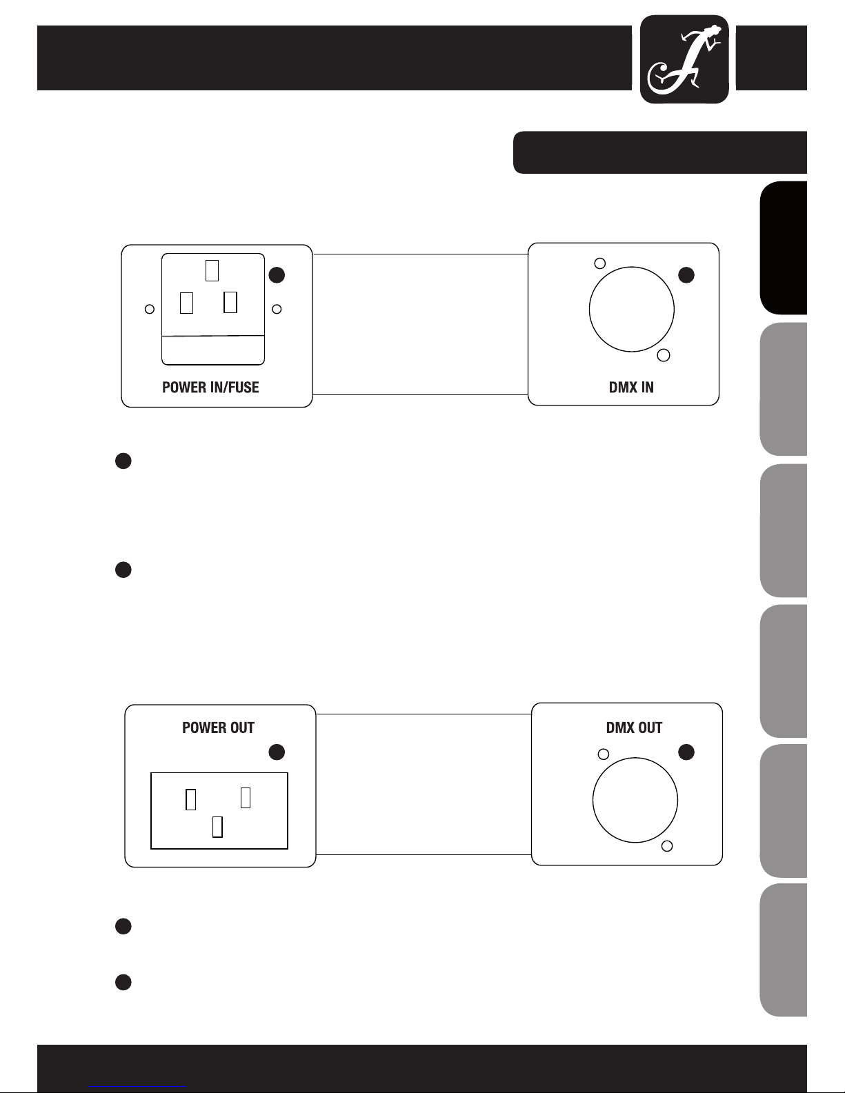
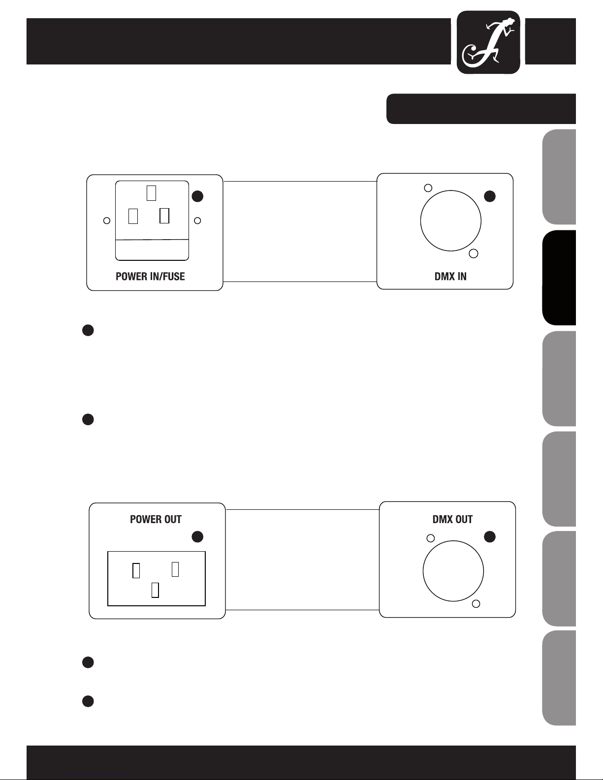
CONNECTIONS:
1
IEC POWER INPUT SOCKET WITH FUSE HOLDER
Operating voltage 110 - 240 V AC / 50 - 60 Hz. Connection via the included IEC power cord.
F3AL / 250 V fuse (5 x 20 mm).
IMPORTANT INFORMATION: Replace the fuse only with a fuse of the same type and rating. If the fuse blows
repeatedly, please contact an authorised service centre.
2
DMX INPUT
3-pole XLR socket for connection of a DMX controller (e.g., DMX mixer).
3
DMX OUTPUT
3-pole XLR socket for looping through the DMX control signal.
4
IEC POWER OUTPUT SOCKET
Used to supply power to additional CAMEO lights (maximum 3 A).
ITALIANOPOLSKIESPAÑOL
FRANCAISFRANCAIS FRANCAISFRANCAIS
FRANCAISDEUTSCHENGLISH
MODE ENTER UP DOWN
1 2
3 4

8
REAR VIEW:
1
MICROPHONE FOR MUSIC CONTROL
2
MODE
Selection of the standalone functions, DMX modes, and DMX address.
3
ENTER
Makes it possible to change a value and confirm changes.
4
UP AND DOWN BUTTONS
Press the UP and DOWN buttons, for example, to change the microphone sensitivity, stroboscope speed or
DMX address.
5
4-DIGIT LED DISPLAY
Displays the operating mode and values of individual functions.
ENGLISHDEUTSCHFRANCAIS
FRANCAISFRANCAIS FRANCAISFRANCAIS
ESpAñoLpoLSKIITALIANo
MODE ENTER UP DOWN
1
2 3 4
5
9
OPERATION:
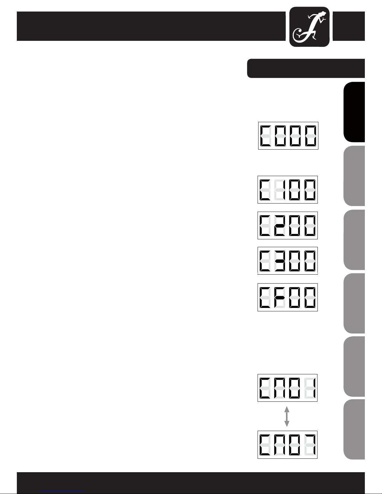
STATIC COLOUR
Press the MODE button repeatedly until "C000" appears on the display.
Press ENTER and then use the UP and DOWN buttons to select the desired
colour or the stroboscopic effect ("C1" = red, "C2" = green, "C3" = blue,
“CF” = stroboscopic effect). The last two numerals stand for the brightness
(00 - 99) and, in "CF" mode, for the stroboscope speed. For example: If you
set C1, C2, and C3 to "00", all LEDs in the projector are off (blackout). If you
set C1 to "99" and C2 and C3 to "00", then the projector emits 100% red.
RED
Intensity 00 - 99
GREEN
Intensity 00 - 99
BLUE
Intensity 00 - 99
STROBE
Stroboscope speed 00 - 99
COLOUR MACROS (7 COLOURS)
Press the MODE button several times if necessary to select the "Colour
Macro" (CM0x) mode. Press the ENTER button and then use the UP and
DOWN buttons to select the desired colour. Confirm your selection by
pressing ENTER.
CM01 = RED
CM02 = GREEN
CM03 = BLUE
CM04 = YELLOW
CM05 = MAGENTA
CM06 = CYAN
CM07 = WHITE
ITALIANOPOLSKIESPAÑOL
FRANCAISFRANCAIS FRANCAISFRANCAIS
FRANCAISDEUTSCHENGLISH

10
OPERATION:
COLOUR CHANGE
Press the MODE button repeatedly until "JU00" appears on the
display. Now the light is in colour change mode. Afterwards, press
ENTER and then use the UP and DOWN buttons to choose the 7
colours function "JU00" or stroboscope "JF00". To set the colourchange and stroboscope rate (00 - 99), press ENTER again (all 4
digits on the display flash) and then use the UP and DOWN buttons
to change the values. Press ENTER again to confirm.
NOTE: Both functions can also be used simultaneously.
7 COLOURS
Rate 00 - 99
STROBE
Rate 00 - 99
COLOUR BLENDING
Press the MODE button repeatedly until "FA00" appears on the display.
Now the light is in colour blending mode. Afterwards, press ENTER
and then use the UP and DOWN buttons to choose the 7 colours
function "FA00" or stroboscope "FF00". To set the colour-blending and
stroboscope rate (00 - 99), press ENTER again (all 4 digits on the display
flash) and then use the UP and DOWN buttons to change the values. Press
ENTER again to confirm.
NOTE: Both functions can also be used simultaneously.
7 COLOURS
Rate 00 - 99
STROBE
Rate 00 - 99
ENGLISHDEUTSCHFRANCAIS
FRANCAISFRANCAIS FRANCAISFRANCAIS
ESpAñoLpoLSKIITALIANo

11
OPERATION:
AUTO MODE
Press the MODE button repeatedly until "AUTO" appears on the display.
In this operating mode, the light switches automatically between colour
change and colour blending mode. The colour change and/or colour
blending rate is determined by the settings of the respective mode.
SLAVE MODE
Press the MODE button repeatedly until "SLAV" appears on the display.
Connect the slave and the master unit with a DMX cable. Now the slave
unit follows the master unit. Confirm with ENTER.
MUSIC CONTROL
Press the MODE button repeatedly until "SUxx" appears on the display.
Now the light is controlled by the built-in microphone and follows the beat
of the music. Now press the ENTER button again (all 4 digits flash) and use
the UP and DOWN buttons to set the sensitivity of the microphone (0 - 99).
Confirm with ENTER.
DMX MODE SELECTION
Press the MODE button repeatedly until one of the four DMX modes
appears on the display (2Ch, 3Ch1, 3Ch2, 6Ch). Press ENTER (all digits
flash) and use the UP and DOWN buttons to select the desired DMX mode.
Confirm with ENTER.
SET DMX START ADDRESS
Press the MODE button repeatedly until "A" and 3 additional digits appear
on the display. Press ENTER (all digits flash) to use the UP and DOWN
buttons to select the desired DMX start address (A001 - A512). Confirm
with ENTER. NOTE: In order to be able to use the light in DMX mode, the
DMX start address mode must be set.
NOTE:
Unless one of the 4 buttons is pressed, the LED display will automatically
switch off after approx. 1 minute. As soon as one of the four buttons is
pressed, the display switches on again.
ITALIANOPOLSKIESPAÑOL
FRANCAISFRANCAIS FRANCAISFRANCAIS
FRANCAISDEUTSCHENGLISH
ENGLISH
SETUP
SETUP
SETUP

12
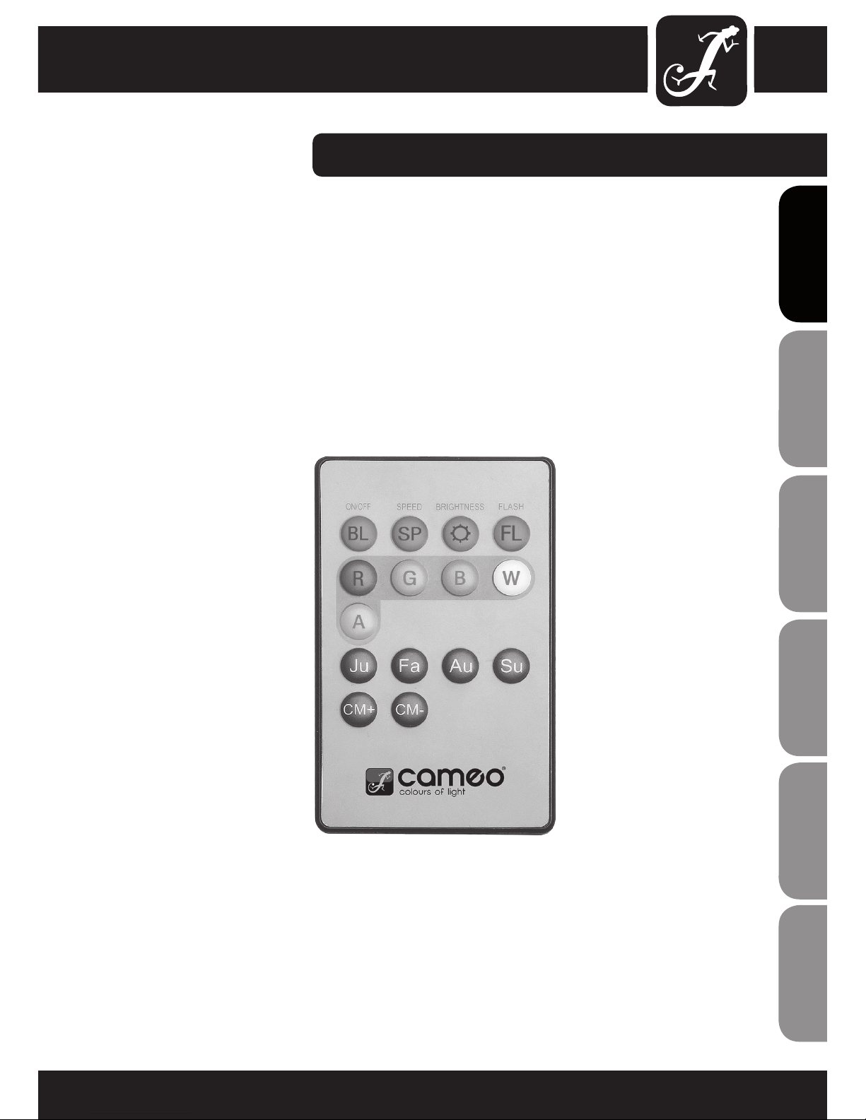
INFRAREDREMOTE CONTROL (optional):
CLPFLAT1REMOTE
Point the infrared remote control directly at the infrared sensor installed on the front of the spotlight. The maximum
range is about 8 metres. In the DMX and slave modes, the sensor of the spotlight is disabled.
BL (Blackout) / ON/OFF
The BL button is used to switch off the spotlights, regardless of the mode selected on the remote control. Pressing
the BL button once more activates the previously selected mode again.
SP (Speed)
4-Level speed setting for the colour change programs Colour Jumping (Ju) and Colour Fading (Fa). Level 1 makes
the colour change sequence run slowly. Pressing again activates Level 2 with a faster colour change sequence,
followed by Level 3 and 4, whereby Level 4 represents the fastest succession of the colour change sequence.
(Brightness)
4-Level brightness setting for the colour change programs (Ju, Fa, Au), the sound control mode (Su) and colour
macros (CM). The brightness level can be adjusted by pressing this button repeatedly.
FL (Flash / stroboscope)
4-Level speed setting for the stroboscope effect. Level 1 deactivates the stroboscope effect, Level 2 represents low,
Level 3 medium, and Level 4 the fastest flash rate. The stroboscope effect can be combined with all colour change
programs (Ju, Fa, Au, Su), the colour macros (CM) and the colour mixing mode RGBWA (depending on model).
R / G / B / W / A (Red, Green, Blue, White, Amber) (depending on model)
These 5 buttons can be used to create individual colour combinations. The 4 levels of brightness can be activated
by pressing the respective colour button repeatedly, whereby at Level 1 the LEDs are switched off.
For example: If you set red and green to their respective highest level and blue and white to their lowest, i.e., off, the
result will be a bright yellow colour mix.
Ju (Colour Change)
The colour change occurs abruptly (Colour Jumping). The speed at which the colours change can be set using
the "SP" (Speed) button.
Fa (Colour blending)
Colours blend into each other (Colour Fading). The speed at which the colours change can be set using the "SP"
(Speed) button.
Au (Automatic Mode)
In this operating mode, the light switches automatically between colour change and colour blending mode. The
colour change and/or colour blending rate is determined by the settings of the respective mode.
ENGLISHDEUTSCHFRANCAIS
FRANCAISFRANCAIS FRANCAISFRANCAIS
ESpAñoLpoLSKIITALIANo
13
INFRAREDREMOTE CONTROL (optional):
Su (Music-Control Colour Changing Program)
The microphone for the sound control mode can be found at the back of the spotlight.
CM (Colour Macros)
Colour presets that can be accessed using the CM+ and CM- buttons. The number of colour presets depends on
the model.
ITALIANOPOLSKIESPAÑOL
FRANCAISFRANCAIS FRANCAISFRANCAIS
FRANCAISDEUTSCHENGLISH
14
DMXCONTROL:
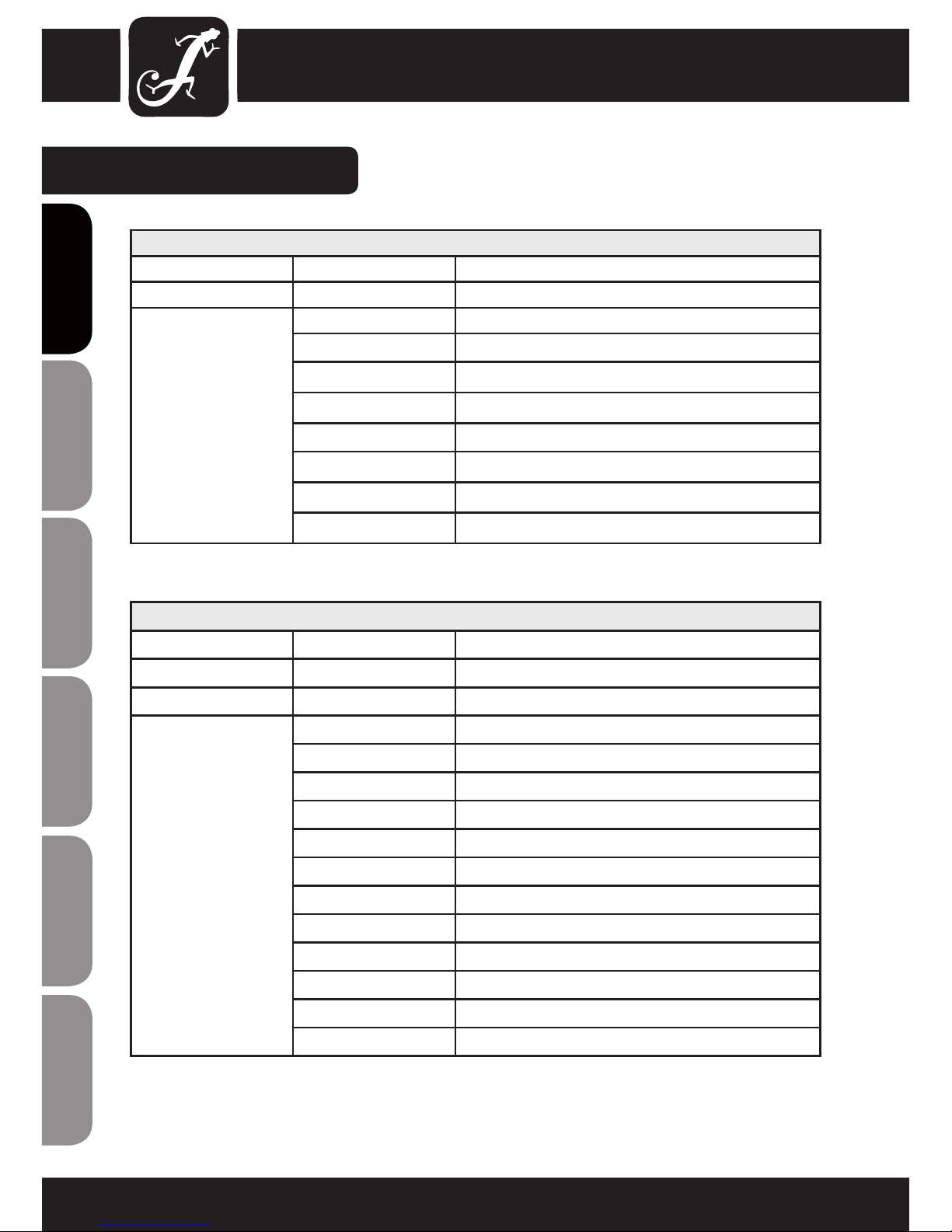
2-CHANNEL MODE
CHANNEL VALUE FUNCTION
CH1 000 - 255 Master dimmer (0-100%)
CH2 000 - 255 Colour macro
000 - 036 Red
037 - 073 Green
074 - 110 Blue
111 - 147 Yellow
148 - 184 Magenta
185 - 221 Cyan
222 - 255 White
3-CHANNEL MODE 1
CHANNEL VALUE FUNCTION
CH1 000 - 255 Master dimmer (0-100%)
CH2 000 - 255 Stroboscope (rate 0 - 100%)
CH3 000 - 080 Colour macro
000 - 004 Blackout
005 - 015 Red
016 - 026 Green
027 - 037 Blue
038 - 048 Yellow
049 - 059 Magenta
060 - 070 Cyan
071 - 080 White
081 - 150 Colour change (rate)
151 - 220 Colour blending (rate)
221 - 255 Music control (microphone sensitivity)
ENGLISHDEUTSCHFRANCAIS
FRANCAISFRANCAIS FRANCAISFRANCAIS
ESpAñoLpoLSKIITALIANo
15
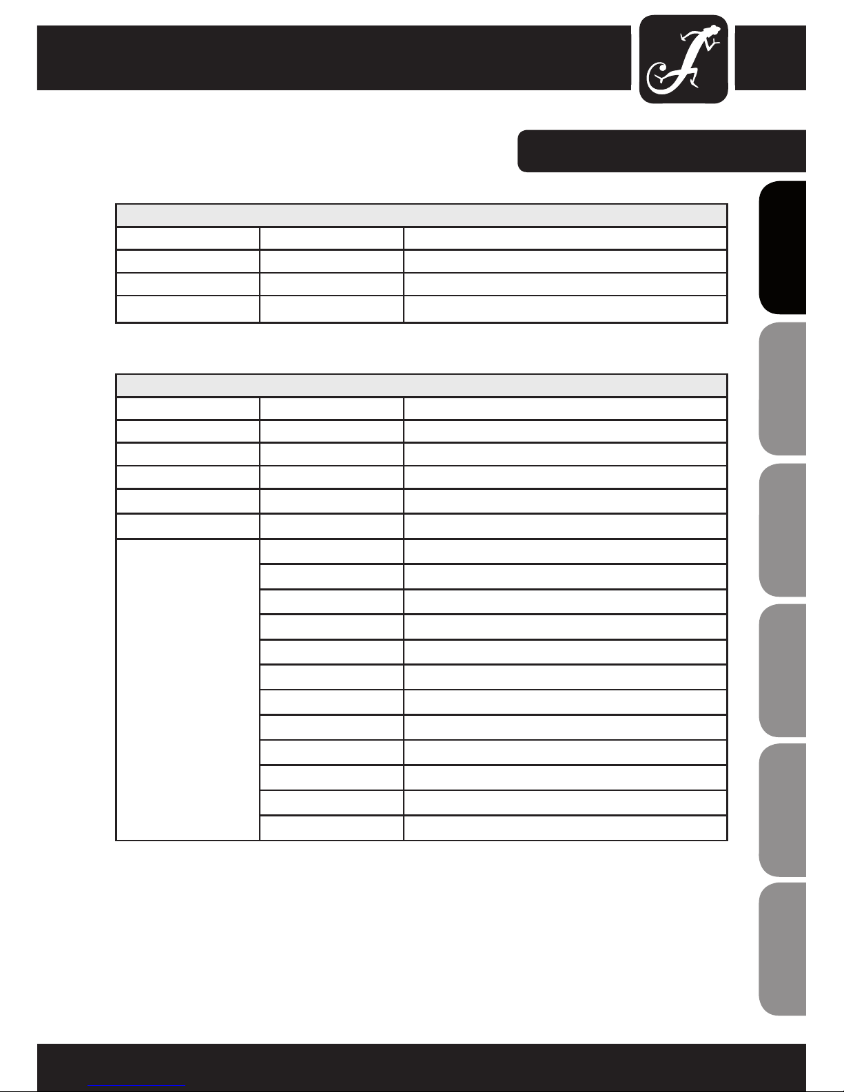
3-CHANNEL MODE 2
CHANNEL VALUE FUNCTION
CH1 000 - 255 Red (0 - 100%)
CH2 000 - 255 Green (0 - 100%)
CH3 000 - 255 Blue (0 - 100%)
DMXCONTROL:
6-CHANNEL MODE
CHANNEL VALUE FUNCTION
CH1 000 - 255 Master dimmer (0-100%)
CH2 000 - 255 Stroboscope (rate 0 - 100%)
CH3 000 - 225 Red (0 - 100%)
CH4 000 - 225 Green (0 - 100%)
CH5 000 - 225 Blue (0 - 100%)
CH6 000 - 080 Colour macro
000 - 004 Blackout / colour mix CH3 - CH5
005 - 015 Red
016 - 026 Green
027 - 037 Blue
038 - 048 Yellow
049 - 059 Magenta
060 - 070 Cyan
071 - 080 White
081 - 150 Colour change (rate)
151 - 220 Colour blending (rate)
221 - 255 Music control (microphone sensitivity)
ITALIANOPOLSKIESPAÑOL
FRANCAISFRANCAIS FRANCAISFRANCAIS
FRANCAISDEUTSCHENGLISH

16
ENGLISHDEUTSCHFRANCAIS
FRANCAISFRANCAIS FRANCAISFRANCAIS
ESpAñoLpoLSKIITALIANo
DMX CONNECTION:
DMX-512
DMX (Digital Multiplex) is the name of a universal transmission protocol for communication between
corresponding devices and controllers. A DMX controller sends DMX data to the connected DMX device(s).
The DMX data is always transmitted as a serial data stream that is forwarded from one connected device to
the next via the "DMX IN" and "DMX OUT" connectors (XLR plug-type connectors) that are found on every
DMX-capable device. (Most controllers only have a DMX output.)
DMX CONNECTION:
DMX is the common "language" via which a very wide range of types and models of equipment from
various manufacturers can be connected with one another and controlled via a central controller, provided
that all of the devices and the controller are DMX-compatible. For optimum data transmission, it is
necessary to keep the connecting cables between the individual devices as short as possible. The order in
which the devices are integrated in the DMX network has no influence on addressing. Thus the device with
the DMX address 1 can be located at any position in the (serial) DMX chain: at the beginning, at the end
or somewhere in the middle. If the DMX address 1 is assigned to a device, the controller "knows" that it
should send all data allocated to address 1 to this device regardless of its position in the DMX network.
The Adam Hall 3 STAR, 4 STAR, and 5 STAR product ranges include an extensive selection of suitable
cables.
SERIAL CONNECTION OF MULTIPLE LIGHTS
1.) Connect the male 3-pole XLR connector of the DMX cable to the DMX output (female 3-pole socket) of
the first light or other DMX device.
2.) Connect the female 3-pole connector of the DMX cable connected to the first light to the DMX input
(male 3-pole socket) of the next DMX device. In like manner, connect the DMX output of this device to the
DMX input of the next device and repeat until all devices have been connected.
Please note that as a rule, DMX devices are connected in series and connections cannot be shared without
active splitters.

17
ITALIANOPOLSKIESPAÑOL
FRANCAISFRANCAIS FRANCAISFRANCAIS
FRANCAISDEUTSCHENGLISH
DMX CABLE:
NOTE:
• When fabricating your own cables, always observe the illustrations on this page. Never connect the shielding
of the cable to the ground contact of the plug, and always make certain that the shielding does not come into
contact with the housing of the XLR plug. If the shielding is connected to ground, this can lead to short-circuiting
and system malfunctions.
PLEASE NOTE: TERMINATION:
• With extended cable runs, the last device in the chain may require a terminating resistor in order to prevent
system malfunctions.
This is achieved by using a cable terminator module (Product No. K3DMXT3).
• Some manufacturers use 5-pole versions for data transmission instead of 3-pole XLR plugs. However, devices
with 5-pole XLR connectors can also be integrated in a DMX network with 3-pole XLR connectors. In this case,
a suitable cable adapter is required. The following illustration shows the correct pin-out of the corresponding
plugs.
Use of a terminating resistor (termination)
reduces interference and other problems during
signal transmission. It is always advisable to
connect a DMX termination module (resistance
120 ohms, 1/4 W) between pole 2 (DMX-) and
pole 3 (DMX+) of the last device in the chain.
Usual connection
DMX-512 output
3-pole XLR
DMX-512 input
3-pole XLR
5-pole XLR(socket)
Pole 1: Ground
(shielding)
Pole 2: Signal (-)
Pole 3: Signal (+)
Pole 4: unused
Pole 5: unused
5-pole XLR(socket)
Pole 1: Ground
(shielding)
Pole 2: Signal (-)
Pole 3: Signal (+)
Pole 4: unused
Pole 5: unused
3-pole XLR(socket)
Pole 1: Ground
(shielding)
Pole 2: Signal (-)
Pole 3: Signal (+)
3-pole XLR(socket)
Pole 1: Ground
(shielding)
Pole 2: Signal (-)
Pole 3: Signal (+)
18
Model Name: CLPFLAT1TRI3WIR CLPFLAT1RGB10IR
Product Type: LED PAR can LED PAR can
Type: flat can flat can
Colour Spectrum: RGB RGB
Number of LEDs: 7 144 (48 x R, 48 x G, 48 x B)
LED Type: 3 W TRI colour 10 mm
Dispersion Angle: 30° 14°
DMX Input: 3-pole XLR male 3-pole XLR male
DMX Output: 3-pole XLR female 3-pole XLR female
DMX Mode: 2-channel, 3-channel1, 3-channel2,
6-channel
2-channel, 3-channel1, 3-channel2,
6-channel
DMX Functions: colour change, colour blending,
music control, stroboscope, RGB
colour change, colour blending,
music control, stroboscope, RGB
Standalone Functions: colour change, colour blending,
music control, stroboscope, static
colours, master/slave operation
Colour Macros:
colour change, colour blending,
music control, stroboscope, static
colours, master/slave operation,
colour macros
Controls: Mode, Enter, Up, Down Mode, Enter, Up, Down
Display Elements: 4-digit LED display 4-digit LED display
Operating Voltage: 110 - 240 V AC / 50 - 60 Hz 110 - 240 V AC / 50 - 60 Hz
Power Consumption: 25 W 15 W
Power Connector: IEC power input and output socket IEC power input and output socket
Cabinet Material: ABS ABS
Housing Colour: black black
Dimensions
(W x H x D, excluding bracket):
176 x 180 x 113 mm 176 x 180 x 113 mm
Weight: 1.2 kg 1.2 kg
Other Features: Absolutely silent thanks to convection
cooling, dual bracket included,
optional IR remote control
(CLPFLAT1REMOTE)
Absolutely silent thanks to convec-
tion cooling, dual bracket included,
optional IR remote control
(CLPFLAT1REMOTE)
SPECIFICATIONS:
ENGLISHDEUTSCHFRANCAIS
FRANCAISFRANCAIS FRANCAISFRANCAIS
ESpAñoLpoLSKIITALIANo
19
ITALIANOPOLSKIESPAÑOL
FRANCAISFRANCAIS FRANCAISFRANCAIS
FRANCAISDEUTSCHENGLISH
MANUFACTURER´S DECLARATIONS:
MANUFACTURER‘S WARRANTY
This warranty covers the Adam Hall, LD Systems, Defender, Palmer, and Cameo brands.
It applies to all products distributed by Adam Hall.
This warranty declaration does not affect the statutory warranty claims against the manufacturer, but expands
them with additional warranty claims vis-a-vis Adam Hall.
Adam Hall warrants that the Adam Hall product that you have purchased from Adam Hall or from an Adam Hall
authorized reseller is free from defects in materials or workmanship under normal use for a period of 2 or 5 years
(please inquire on a product-by-product basis) from the date of purchase.
The warranty period begins on the date on which the product was purchased, proof of which must be produced
(through presentation of the invoice or the delivery note with the date of purchase) in the event of a warranty claim.
Should products of the brands named above be in need of repair within the limited warranty period, you are entitled
to warranty service according to the terms and conditions stated here.
During the Limited Warranty Period, Adam Hall will repair or replace the defective component parts or the product.
In the event of repair or replacement during the Limited Warranty Period, the replaced original parts and/or products become property of Adam Hall.
In the unlikely event that the product which you purchased has a recurring failure, Adam Hall has the right, at its
discretion, to replace the defective product with another product, provided that the new product is at least equivalent to the product being replaced with regard to the technical specifications.
Adam Hall does not warrant that the operation of this product will be uninterrupted or error-free. Adam Hall is not
responsible for damage that occurs as a result of your failure to follow the instructions included with the Adam Hall
branded product. The manufacturer‘s warranty does not cover – expendable parts (e. g., rechargeable batteries)
- products from which the serial number has been removed or with a serial number that has been damaged as a
result of an accident - damage due to improper use, user error or other external reasons
- damage to devices operated outside the usage parameters stated in the documentation included with the product
- damage due to the use of replacement parts not manufactured, sold or recommended by Adam Hall,
- damage due to modification or servicing by anyone other than Adam Hall.
These terms and conditions constitute the complete and exclusive warranty agreement between you and Adam
Hall regarding the Adam Hall branded product you have purchased.
20
ENGLISHDEUTSCHFRANCAIS
FRANCAISFRANCAIS FRANCAISFRANCAIS
ESpAñoLpoLSKIITALIANo
MANUFACTURER´S DECLARATIONS:
LIMITATION OF LIABILITY
If your Adam Hall branded hardware product fails to work as warranted above, your sole and exclusive remedy
shall be repair or replacement. Adam Halls’ maximum liability under this limited warranty is expressly limited to
the lesser of the price you have paid for the product or the cost of repair or replacement of any components that
malfunction under conditions of normal use.
Adam Hall is not liable for any damages caused by the product or the failure of the product, including any lost
profits or savings or special, incidental, or consequential damages. Adam Hall is not liable for any claim made by
a third party or made by you for a third party.
This limitation of liability applies whether damages are sought, or claims are made, under this Limited Warranty
or as a tort claim (including negligence and strict product liability), a contract claim, or any other claim, and
cannot be rescinded or changed by anyone. This limitation of liability will be effective even if you have advised
Adam Hall or an authorized representative of Adam Hall of the possibility of any such damages, but not, however,
in the event of claims for damages in connection with personal injuries.
This manufacturer‘s warranty grants you specific rights; depending on jurisdiction (nation or state), you may be
be entitled to additional claims. You are advised to consult applicable state or national laws for a full determination of your rights.
REQUESTING WARRANTY SERVICE
To request warranty service for the product, contact Adam Hall or the Adam Hall authorized reseller from which
you purchased the product.
EC DECLARATION OF CONFORMITY
The equipment marketed by Adam Hall complies (where applicable) with the essential requirements and other
relevant specications of Directives 1999/5/EC (R&TTE), 2004/108/EC (EMC) und 2006/95/EC (LVD). Additional
information can be found at www.adamhall.com.
21
ITALIANOPOLSKIESPAÑOL
FRANCAISFRANCAIS FRANCAISFRANCAIS
FRANCAISDEUTSCHENGLISH
MANUFACTURER´S DECLARATIONS:
PROPER DISPOSAL OF THIS PRODUCT
(Valid in the European Union and other European countries with waste separation)
This symbol on the product, or the documents accompanying the product, indicates that this appliance may not
be treated as household waste. This is to avoid environmental damage or personal injury due to uncontrolled
waste disposal. Please dispose of this product separately from other waste and have it recycled to promote
sustainable economic activity.
Household users should contact either the retailer where they purchased this product, or their local government
office, for details on where and how they can recycle this item in an environmentally friendly manner.
Business users should contact their supplier and check the terms and conditions of the purchase contract. This
product should not be mixed with other commercial wastes for disposal .
ENVIRONMENTAL PROTECTION AND ENERGY CONSERVATION
Energy conservation is an active contribution to environmental protection. Please turn off all unneeded electrical
devices. To prevent unneeded devices from consuming power in standby mode, disconnect the mains plug.
Adam Hall GmbH, all rights reserved. The technical data and the functional product characteristics can be subject
to modifications. The photocopying, the translation, and all other forms of copying of fragments or of the integrlity
of this user’s manual is prohibited.

22
Einleitung
Cameo CLPFLAT1TRI3WIR und CLPFLAT1RGB10IR - lichtstark, leicht und kompakt!
Die über eine Infrarot-Fernbedienung steuerbaren LED-Strahler von Cameo sind besonders flache, lichtstarke PARScheinwerfer, die das RGB-Spektrum abdecken. Die leichte und kompakte ABS-Konstruktion mit Doppelbügel eignet
sich für flexiblen und geräuschlosen Einsatz, sie benötigt dank der extrem geringen Wärmeentwicklung keinen Lüfter.
ENGLISHDEUTSCHFRANCAIS
FRANCAISFRANCAIS FRANCAISFRANCAIS
ESpAñoLpoLSKIITALIANo
Wir freuen uns, dass Sie sich für ein Produkt von Cameo Light entschieden haben!
Dieses Gerät wurde unter hohen Qualitätsanforderungen entwickelt und gefertigt, um viele Jahre einen reibungslosen Betrieb zu gewährleisten.
Bitte lesen Sie diese Bedienungsanleitung sorgfältig, damit Sie Ihren neuen Scheinwerfer von Cameo Light
schnell optimal einsetzen können.
Weitere Informationen über Cameo Light erhalten Sie auf unserer Website WWW.CAMEOLIGHT.COM.

23
ITALIANOPOLSKIESPAÑOL
FRANCAISFRANCAIS FRANCAISFRANCAIS
FRANCAISDEUTSCHENGLISH
FLAT PAR CAN TRI 3W IR
CLPFLAT1TRI3WIR
FLAT PAR CAN RGB 10 IR
CLPFLAT1RGB10IR

24
ENGLISHDEUTSCHFRANCAIS
FRANCAISFRANCAIS FRANCAISFRANCAIS
ESpAñoLpoLSKIITALIANo
SICHERHEITSHINWEISE:
1. Lesen Sie diese Anleitung bitte sorgfältig durch.
2. Bewahren Sie alle Informationen und Anleitungen an einem sicheren Ort auf.
3. Befolgen Sie die Anweisungen.
4. Beachten Sie alle Warnhinweise. Entfernen Sie keine Sicherheitshinweise oder andere Informationen vom Gerät.
5. Verwenden Sie das Gerät nur in der vorgesehenen Art und Weise.
6. Verwenden Sie ausschließlich stabile und passende Stative bzw. Befestigungen (bei Festinstallationen). Stellen
Sie sicher, dass Wandhalterungen ordnungsgemäß installiert und gesichert sind. Stellen Sie sicher, dass das
Gerät sicher installiert ist und nicht herunterfallen kann.
7. Beachten Sie bei der Installation die für Ihr Land geltenden Sicherheitsvorschriften.
8. Installieren und betreiben Sie das Gerät nicht in der Nähe von Heizkörpern, Wärmespeichern, Öfen oder
sonstigen Wärmequellen. Sorgen Sie dafür, dass das Gerät immer so installiert ist, dass es ausreichend gekühlt
wird und nicht überhitzen kann.
9. Platzieren Sie keine Zündquellen wie z.B. brennende Kerzen auf dem Gerät.
10. Lüftungsschlitze dürfen nicht blockiert werden.
11. Betreiben Sie das Gerät nicht in unmittelbarer Nähe von Wasser (gilt nicht für spezielle Outdoor Geräte beachten Sie in diesem Fall bitte die im Folgenden vermerkten Sonderhinweise). Bringen Sie das Gerät nicht mit
brennbaren Materialien, Flüssigkeiten oder Gasen in Berührung.
12. Sorgen Sie dafür, dass kein Tropf- oder Spritzwasser in das Gerät eindringen kann. Stellen Sie keine mit
Flüssigkeit gefüllten Behältnisse wie Vasen oder Trinkgefäße auf das Gerät.
13. Sorgen Sie dafür, dass keine Gegenstände in das Gerät fallen können.
14. Betreiben Sie das Gerät nur mit dem vom Hersteller empfohlenen und vorgesehenen Zubehör.
15. Öffnen Sie das Gerät nicht und verändern Sie es nicht.
16. Überprüfen Sie nach dem Anschluss des Geräts alle Kabelwege, um Schäden oder Unfälle, z. B. durch
Stolperfallen zu vermeiden.
17. Achten Sie beim Transport darauf, dass das Gerät nicht herunterfallen und dabei möglicherweise Sach- und
Personenschäden verursachen kann.
18. Wenn Ihr Gerät nicht mehr ordnungsgemäß funktioniert, Flüssigkeiten oder Gegenstände in das Geräteinnere
gelangt sind, oder das Gerät anderweitig beschädigt wurde, schalten Sie es sofort aus und trennen es von der
Netzsteckdose (sofern es sich um ein aktives Gerät handelt). Dieses Gerät darf nur von autorisiertem Fachpersonal repariert werden.
19. Verwenden Sie zur Reinigung des Geräts ein trockenes Tuch.
20. Beachten Sie alle in Ihrem Land geltenden Entsorgungsgesetze. Trennen Sie bei der Entsorgung der Verpackung bitte Kunststoff und Papier bzw. Kartonagen voneinander.
21. Kunststoffbeutel müssen außer Reichweite von Kindern aufbewahrt werden.
BEI GERÄTEN MIT NETZANSCHLUSS:
22. ACHTUNG: Wenn das Netzkabel des Geräts mit einem Schutzkontakt ausgestattet ist, muss es an einer
Steckdose mit Schutzleiter angeschlossen werden. Deaktivieren Sie niemals den Schutzleiter eines Netzkabels.
23. Schalten Sie das Gerät nicht sofort ein, wenn es starken Temperaturschwankungen ausgesetzt war (beispielsweise nach dem Transport). Feuchtigkeit und Kondensat könnten das Gerät beschädigen. Schalten Sie das
Gerät erst ein, wenn es Zimmertemperatur erreicht hat.
24. Bevor Sie das Gerät an die Steckdose anschließen, prüfen Sie zuerst, ob die Spannung und die Frequenz
des Stromnetzes mit den auf dem Gerät angegebenen Werten übereinstimmen. Verfügt das Gerät über einen
Spannungswahlschalter, schließen Sie das Gerät nur an die Steckdose an, wenn die Gerätewerte mit den Werten
des Stromnetzes übereinstimmen. Wenn das mitgelieferte Netzkabel bzw. der mitgelieferte Netzadapter nicht in
Ihre Netzsteckdose passt, wenden Sie sich an Ihren Elektriker.

25
ITALIANOPOLSKIESPAÑOL
FRANCAISFRANCAIS FRANCAISFRANCAIS
FRANCAISDEUTSCHENGLISH
SICHERHEITSHINWEISE:
25. Treten Sie nicht auf das Netzkabel. Sorgen Sie dafür, dass spannungsführende Kabel speziell an der Netzbuchse bzw. am Netzadapter und der Gerätebuchse nicht geknickt werden.
26. Achten Sie bei der Verkabelung des Geräts immer darauf, dass das Netzkabel bzw. der Netzadapter stets frei
zugänglich ist. Trennen Sie das Gerät stets von der Stromzuführung, wenn das Gerät nicht benutzt wird, oder
Sie das Gerät reinigen möchten. Ziehen Sie Netzkabel und Netzadapter immer am Stecker bzw. am Adapter und
nicht am Kabel aus der Steckdose. Berühren Sie Netzkabel und Netzadapter niemals mit nassen Händen.
27. Schalten Sie das Gerät möglichst nicht schnell hintereinander ein und aus, da sonst die Lebensdauer des
Geräts beeinträchtigt werden könnte.
28. WICHTIGER HINWEIS: Ersetzen Sie Sicherungen ausschließlich durch Sicherungen des gleichen Typs und
Wertes. Sollte eine Sicherung wiederholt auslösen, wenden Sie sich bitte an ein autorisiertes Servicezentrum.
29. Um das Gerät vollständig vom Stromnetz zu trennen, entfernen Sie das Netzkabel bzw. den Netzadapter aus
der Steckdose.
30. Wenn Ihr Gerät mit einem Volex-Netzanschluss bestückt ist, muss der passende Volex-Gerätestecker
entsperrt werden, bevor er entfernt werden kann. Das bedeutet aber auch, dass das Gerät durch ein Ziehen am
Netzkabel verrutschen und herunterfallen kann, wodurch Personen verletzt werden und/oder andere Schäden
auftreten können. Verlegen Sie Ihre Kabel daher immer sorgfältig.
31. Entfernen Sie Netzkabel und Netzadapter aus der Steckdose bei Gefahr eines Blitzschlags oder wenn Sie das
Gerät länger nicht verwenden.
CAUTION
RISK OF ELECTRIC SHOCK
DO NOT OPEN
ACHTUNG:
Entfernen Sie niemals die Abdeckung, da sonst das Risiko eines elektrischen Schlages besteht. Im Inneren des
Geräts befinden sich keine Teile, die vom Bediener repariert oder gewartet werden können. Lassen Sie Reparaturen ausschließlich von qualifiziertem Servicepersonal durchführen.
Das gleichschenkelige Dreieck mit Blitzsymbol warnt vor nichtisolierten, gefährlichen Spannungen
im Geräteinneren, die einen elektrischen Schlag verursachen können.
Das gleichschenkelige Dreieck mit Ausrufungszeichen kennzeichnet wichtige Bedienungs- und
Wartungshinweise.
ACHTUNG HOHE LAUTSTÄRKEN BEI AUDIOPRODUKTEN!
Dieses Gerät ist für den professionellen Einsatz vorgesehen. Der kommerzielle Betrieb dieses Geräts unterliegt
den jeweils gültigen nationalen Vorschriften und Richtlinien zur Unfallverhütung. Als Hersteller ist Adam Hall
gesetzlich verpflichtet, Sie ausdrücklich auf mögliche Gesundheitsrisiken hinzuweisen.
Gehörschäden durch hohe Lautstärken und Dauerbelastung: Bei der Verwendung dieses Produkts können
hohe Schalldruckpegel (SPL) erzeugt werden, die bei Künstlern, Mitarbeitern und Zuschauern zu irreparablen
Gehör¬schäden führen können. Vermeiden Sie länger anhaltende Belastung durch hohe Lautstärken über 90 dB.
VORSICHT! WICHTIGE HINWEISE IN BEZUG AUF LICHT-PRODUKTE
1. Blicken Sie nicht aus Entfernungen von unter 40 cm in den Lichtstrahl.
2. Blicken Sie niemals längere Zeit aus kurzem bis mittlerem Abstand in den Lichtstrahl.
3. Blicken Sie niemals mit optischen Geräten wie Vergrößerungsgläsern in den Lichtstrahl.
4. Stoboskopeffekte können unter Umständen bei empfindlichen Menschen epileptische Anfälle auslösen! Epilepsiekranke Menschen sollten daher unbedingt Orte meiden, an denen Stroboskope eingesetzt werden.

26
EINFÜHRUNG:
FLAT PAR CAN TRI 3W IR
(CLPFLAT1TRI3WIR)
STEUERUNGSFUNKTIONEN:
• 2-Kanal, 3-Kanal 1, 3-Kanal 2, 6-Kanal DMX-
Steuerung
• Separate Steuerung der Farben Rot, Grün und Blau
• Steuerung über optionale Infrarot-Fernbedienung
EIGENSCHAFTEN:
• 7 leuchtstarke TRI-Colour-LEDs (3W)
• Musiksteuerung über eingebautes Mikrofon
• Farbwechselgeschwindigkeit und Stroboskopeffekt
über Bedienpanel steuerbar
• Multicolour-Farbwechsel
• Master/Slave-Funktionalität
• Robustes, flaches Gehäuse
• Leistungsaufnahme: 25 W
• Konvektionskühlung, dadurch absolut geräuschlos
• Longlife-LEDs mit besonders langer Lebensdauer
• Doppelhalterung
• Infrarot-Fernbedienung (optional)
FLAT PAR CAN RGB 10 IR
(CLPFLAT1RGB10IR)
STEUERUNGSFUNKTIONEN:
• 2-Kanal, 3-Kanal 1, 3-Kanal 2, 6-Kanal DMX-
Steuerung
• Separate Steuerung der Farben Rot, Grün und Blau
• Steuerung über optionale Infrarot-Fernbedienung
EIGENSCHAFTEN:
• 144 leuchtstarke 10 mm LEDs (48 x Rot, 48 x Grün,
48 x Blau)
• Musiksteuerung über eingebautes Mikrofon
• Farbwechselgeschwindigkeit und Stroboskopeffekt
über Bedienpanel steuerbar
• Multicolour-Farbwechsel
• Master/Slave-Funktionalität
• Robustes, flaches Gehäuse
• Leistungsaufnahme: 15 W
• Konvektionskühlung, dadurch absolut geräuschlos
• Longlife-LEDs mit besonders langer Lebensdauer
• Doppelhalterung
• Infrarot-Fernbedienung (optional)
BEDIENUNG:
Die Cameo FLAT PAR Scheinwerfer sind DMX-512-steuerbare LED-Strahler mit RGB-Farbmischung, die
sich durch hocheffiziente, besonders helle LEDs auszeichnen. Die Intensität der drei Farbgruppen (rot, grün,
blau) kann unabhängig voneinander gesteuert werden und ermöglicht auf diese Weise eine unbegrenzte Zahl
unterschiedlicher Farben.
Der Cameo LED-Strahler lässt sich sowohl einzeln als auch im Master/Slave-Betrieb, per Musiksteuerung, via
DMX-512-Protokoll und über eine optionale Infrarot-Fernbedienung betreiben.
ENGLISHDEUTSCHFRANCAIS
FRANCAISFRANCAIS FRANCAISFRANCAIS
ESpAñoLpoLSKIITALIANo
27
ANSCHLÜSSE:
1
IEC-NETZEINGANGSBUCHSE MIT SICHERUNGSHALTER
Betriebsspannung 110 - 240 V AC / 50 - 60 Hz. Anschluss über das mitgelieferte IEC-Netzkabel.
Sicherung F3AL / 250V (5 x 20 mm).
WICHTIGER HINWEIS: Ersetzen Sie die Sicherung ausschließlich durch eine Sicherung des gleichen Typs und
mit gleichen Werten. Sollte die Sicherung wiederholt auslösen, wenden Sie sich bitte an ein autorisiertes
Servicezentrum.
2
DMX-EINGANG
3-polige XLR-Buchse zum Anschließen eines DMX-Kontrollgerätes (z.B. DMX-Mischpult).
3
DMX-AUSGANG
3-polige XLR-Buchse zum Weiterleiten des DMX-Steuersignals.
4
IEC-NETZAUSGANGSBUCHSE
Dient der Netzversorgung weiterer CAMEO Scheinwerfer (maximal 3A).
ITALIANOPOLSKIESPAÑOL
FRANCAISFRANCAIS FRANCAISFRANCAIS
FRANCAISDEUTSCHENGLISH
MODE ENTER UP DOWN
1 2
3 4

28
RÜCKANSICHT:
1
MIKROFON FÜR DIE MUSIKSTEUERUNG
2
MODE
Auswählen der Stand-Alone-Funktionen, DMX-Modi und DMX-Adresse.
3
ENTER
Ermöglicht einen Wert zu ändern und Wertänderungen zu bestätigen.
4
UP UND DOWN TASTEN
Betätigen Sie die UP und DOWN Tasten, um z.B. Mikrofonempfindlichkeit, Stroboskopgeschwindigkeit, oder
DMX-Adresse zu ändern.
5
4-STELLIGES LED DISPLAY
Zeigt Betriebsmodus und Werte einzelner Funktionen an.
ENGLISHDEUTSCHFRANCAIS
FRANCAISFRANCAIS FRANCAISFRANCAIS
ESpAñoLpoLSKIITALIANo
MODE ENTER UP DOWN
1
2 3 4
5

29
BEDIENUNG:
STATISCHE FARBE
Drücken Sie die MODE-Taste so oft, bis im Display "C000" erscheint. Drücken
Sie ENTER und wählen anschließend mittels der Tasten UP und DOWN die
gewünschte Farbe, oder den Stroboskopeffekt aus ("C1" = Rot, "C2" = Grün,
"C3" = Blau, “CF” = Stroboskopeffekt). Die beiden folgenden Ziffern stehen für
die Helligkeit (00 - 99) und im "CF"-Modus für die Stroboskopgeschwindigkeit.
Beispiele: Wenn Sie C1, C2 und C3 auf "00" setzen, sind alle LEDs des
Scheinwerfers aus (Blackout). Wenn Sie C1 auf "99" und C2 und C3 auf "00"
setzen, leuchtet der Scheinwerfer zu 100% rot.
ROT
Intensität 00 - 99
GRÜN
Intensität 00 - 99
BLAU
Intensität 00 - 99
STROBE
Stroboskopgeschwindigkeit 00 - 99
FARBMAKROS (7 FARBEN)
Drücken Sie die MODE-Taste gegebenenfalls mehrmals um die Betriebsart
„Colour Macro“ (CM0x) auszuwählen. Drücken Sie auf ENTER und wählen
dann mit Hilfe der Tasten UP und DOWN die gewünschte Farbe aus. Bestätigen
Sie Ihre Auswahl mit ENTER.
CM01 = ROT
CM02 = GRÜN
CM03 = BLAU
CM04 = GELB
CM05 = MAGENTA
CM06 = CYAN
CM07 = WEISS
ITALIANOPOLSKIESPAÑOL
FRANCAISFRANCAIS FRANCAISFRANCAIS
FRANCAISDEUTSCHENGLISH

30
BEDIENUNG:
FARBWECHSEL
Drücken Sie die MODE-Taste so oft, bis im Display "JU00"
erscheint. Der Scheinwerfer arbeitet nun im FarbwechselBetrieb. Drücken Sie anschließend auf ENTER um dann mittels
der Tasten UP und DOWN die Funktion 7 Farben "JU00",
oder Stroboskop "JF00" auszuwählen. Die Farbwechsel- und
Stroboskopgeschwindigkeit (00 - 99) stellen Sie ein, indem Sie
nochmals auf ENTER drücken (alle 4 Ziffern des Displays blinken)
und dann mit Hilfe der UP und DOWN Tasten die Werte verändern.
Zum Bestätigen nochmals ENTER drücken.
Hinweis: Beide Funktionen können auch simultan genutzt werden.
7 FARBEN
Geschwindigkeit 00 - 99
STROBE
Geschwindigkeit 00 - 99
FARBÜBERBLENDEN
Drücken Sie die MODE-Taste so oft, bis im Display "FA00" erscheint. Der
Scheinwerfer arbeitet nun im Farbüberblendungsmodus. Drücken Sie
anschließend auf ENTER um dann mittels der Tasten UP und DOWN die
Funktion 7 Farben "FA00", oder Stroboskop "FF00" auszuwählen. Die
Farbüberblendungs- und Stroboskopgeschwindigkeit (00 - 99) stellen Sie
ein, indem Sie nochmals auf ENTER drücken (alle 4 Ziffern des Displays
blinken) und dann mit Hilfe der UP und DOWN Tasten die Werte verändern.
Zum Bestätigen nochmals ENTER drücken.
Hinweis: Beide Funktionen können auch simultan genutzt werden.
7 FARBEN
Geschwindigkeit 00 - 99
STROBE
Geschwindigkeit 00 - 99
ENGLISHDEUTSCHFRANCAIS
FRANCAISFRANCAIS FRANCAISFRANCAIS
ESpAñoLpoLSKIITALIANo
 Loading...