

Page 1
CANCELLI AUTOMATICI
SET
COMPLETE
U5000
Automazione per porte basculanti
Automatic opening system for overhead doors
Automatisme pour porte basculante
Antriebssystem für Schwingtore
Automatización para puerta basculante
Documentazione
Tecnica
M33
rev. 4.6
05/2002
©
CAME
CANCELLI
AUTOMATICI
119EM33
2
6
5
RG 58
4
3
2 X 1,5
8
1
2 X 1
3 X 1,5
4 X 1
2 X 1
9
7
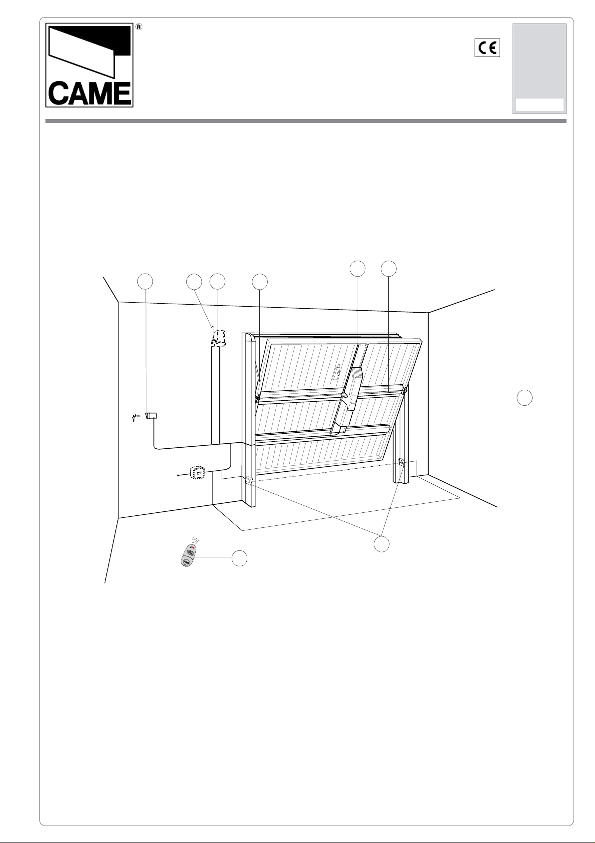
1 - Gruppo motore con
quadro comando e
lampada di illuminazione
2 - Base-motore e
prolunghe di fissaggio
3 - Bracci telescopici
dritti
4 - Lampeggiatore di
movimento
5 - Antenna di ricezione
6 - Selettore a chiave
7 - Trasmettitore radio
8 - Tubo di trasmissione
25 x 25 x 2.5 mm. (da
acquistare
separatamente)
9 - Fotocellule di sicurez-
za
1 - Motor unit with control
panel and lamp for
illumi-nating door area
2 - Motor-base with
mounting extensions
3 - Straight telescopic
arms with installation
acces-sories
4 - Flashing light indicating
door movement
5 - Radio antenna
6 - Key-operated selector
switch
7 - Radio trasmitter
8 - Transmission tube 25 x
25 x 2,5 mm.
9 - Safety photocells
1 - Groupe moteur avec
ar-moire de
commande et lampe
d'éclairage du lieu
2 - Base-moteur et rallon-
ges de fixation
3 - Bras télescopiques
droits et accessoires
de montage
4 - Clignotant de mouve-
ment
5 - Antenne de réception
6 - Sélecteur à clé
7 - Émetteur radio
8 - Tube de trasnsmission
25 x 25 x 2,5 mm.
9 - Photocellules de sécu-
rité
1 - Antriebsaggregat mit
Schalttafel und
Raumbe-leuchtung
2 - Motorträger und Befesti-
gungsverlängerungen
3 - Gerade Teleskopaus
lege-arme
undentsprchen des
Montagezubehör
4 - Blinkleuchte zur
Anzeige der
Torbewegung
5 - Empfangsantenne
6 - Schlüsselschalter
7 - Funksender
8 -Transmissionsstange 25
x 25 x 2,5 mm.
9- Lichtschranken
1 - Grupo motor con
cua-dro de mando y
lámpara para la
iluminación del
ambiente
2 - Base-motor y
extensio-nes de
fijación
3 - Brazos telescópicos
rectos y todos los
accesorios de
montaje
4 - Lámpara intermitente
de movimiento
5 - Antena de recepción
6 - Selector a llave
7 - Radiotransmisor
8 - Tubo de transmisión
25 x 25 x 2,5 mm.
9 - Fotocélulas de seguri-
dad
Page 2
Caratteristiche generali -
Allgemeine merkmale
General characteristics -
- Caracteristícas generales
Caractéristiques generales
Descrizione:
- Motoriduttore
idoneo alla
movimentazione di
porte basculanti fino
a 7 m2.
- Progettato e
costruitio interamente dalla CAME
CANCELLI AUTOMATICI S.p.A.,
rispondono alle
vigenti norme di
sicurezza, con grado
di protezione IP 40.
- Garantito 24 mesi
salvo manomissioni.
Attenzione!
Controllate che le
apparecchiature di
comando, di sicurezza
e gli accessori siano
originali CAME; ciò
garantisce e rende
l'impianto di facile
esecuzione e manutenzione.
Description:
- Gearmotor unit can
be used to power
overhead doors with
surface area of up to
7 m2.
- Designed and
construc-ted entirely
by CAME CANCELLI
AUTOMATICI S.p.A.
in full compliance with
safety standards, with
IP 40 protection
rating.
- Guaranteed for
24months unless
tampered with.
Important!
Check that all control
and safety systems and
accessories are
original CAME
products; this will
ensure that the system
is simple to install and
to maintain.
Description:
- Motoréducteur
indiqué pour
déplacer des portes
basculantes jusqu’à
7 m2.
- Il a été entièrement
conçu et construit
par CAME CANCELLI AUTOMATICI
S.p.A., conformément aux normes
de sécurité en
vigueur avec degré
de protectionIP 40.
- Garanti 24 mois sauf
en cas d'altérations.
Attention!
Vérifiez que
l'appareillage de
commande, de sécurité
et les accessoires sont
des produit originaux
CAME afin de garantir
l'instal-lation et d'en
faciliter le montage et
l'entretien.
Beschreibung:
- Getriebemotor für den
Antrieb von bis zu 7
m² großen
Schwingtoren.
- Vollkommen von der
CAME CANCELLI
AUTOMATICI S.p.A.
den gel-tenden
Sicherheits-normen
entwickelt und hergestellt, mit Schutzgrad
IP 40.
- 24 Monate Garantie,
vorbehaltlich unsachgemäßer
Handhabung und
Montage.
Achtung!
Wir empfehlen, original
CAME-Steuergeräte
und
Sicherheitsvorrichtungen
mit dem
entsprechenden
Zubehör zu installieren,
um eine einwandfreie
montage und
problemlose
Wartung der Anlage
gewährleisten zu
können.
Descripción:
- Motorreductor
idóneo para el
movimiento de
puertas basculantes
de hasta 7 m².
- Diseñado y
fabricado
enteramente por
CAME CANCELLI
AUTOMATICI S.p.A.,
cumpliendo con las
normas de
seguridad vigentes
con grado de
protección IP 40.
- Garantizado 24
meses salvo
manipulaciones.
Atención!
Combrobar que los
equipos de mando, de
seguridad y los accesorios sean originales
CAME; lo cual
garantiza y facilita el
uso y el
mantenimiento del
aparato.
Caratteristiche tecniche -
Motoriduttore
Gear motor
Motoreducteur
Getribemotor
Motorreductor
E600A 1.0 230V a.c. 1.3A 150W 30% IP40 *300N-m 15 s 10 µF 21,5 Kg
Versione
Version
Version
Version
Version
Alimentazione
Power supply
Alimentation
Stromversorgung
Alimentación
Tecnichal caracteristics
Tecnische Daten -
Corrente
nominale
Nominal current
Courant nomi nal
Nennstrom
Corriente nominal
Potenza
Power
Puissance
Leistung
Potencia
- Caractéristiques techniques
Características técnicas
Intermittenza
lavoro
Duty cicle
Intermittence
de travail
Einschaltdauer
Intermitencia
trabajo
Grado di
protezione
Degree of protection
Degre de
protection
Schutzgrad
Grado de
proteción
Coppia
Torque
Couple
Drehmoment
Par
Tempo cor sa
Travel ti m e
Temps course
Laufzeit
Tiempo de
recorrido
Condensatore
Capacitor
Condensateur
Kondensator
Condensador
Dati relativi ai valori di alimentazione nominale. *Regolabile mediante quadro comando CAME.
These technical specifications apply when unit is powered at nominal voltage. *Adjustable using CAME control panel.
Données relatives aux valeurs d'alimentation nominale. *Réglable au moyen du armoire de commande CAME
Daten der Stromversorgungsnennwerte. *Über CAME-Shalttafel regelbar
Datos relativos a los valores de alimentación nominal. *Ajustable mediante los quadros de mando CAME.
2
Peso
Weight
Poids
Gewicht
Peso
Page 3
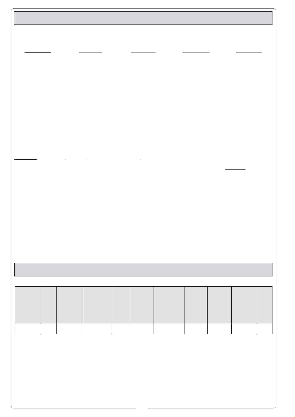
Misure d'ingombro -
External dimensions
- Measures d'encombrent -
Abmessungen
- Dimensiones
120
Esempi d'applicazione -
Applicazione centrale
Central installation
Application centrale
Zentrale Installation
Aplicación central
790
Examples of applications
Installationsbeispiele -
100
- Exemples d'applications
Ejemplos de aplicación
Applicazione laterale
Lateral installation
Application latérale
Seitliche Installation
Aplicación lateral
3
Page 4
PRIMA DELL'INSTALLAZIONE ... -
VOR DEN INSTALLATION ÜBERPRÜFEN
BEFORE INSTALLING .....
... - ANTES DE INSTALAR EL AUTOMATISMO...
- AVANT D'INSTALLER L'AUTOMATISME .....
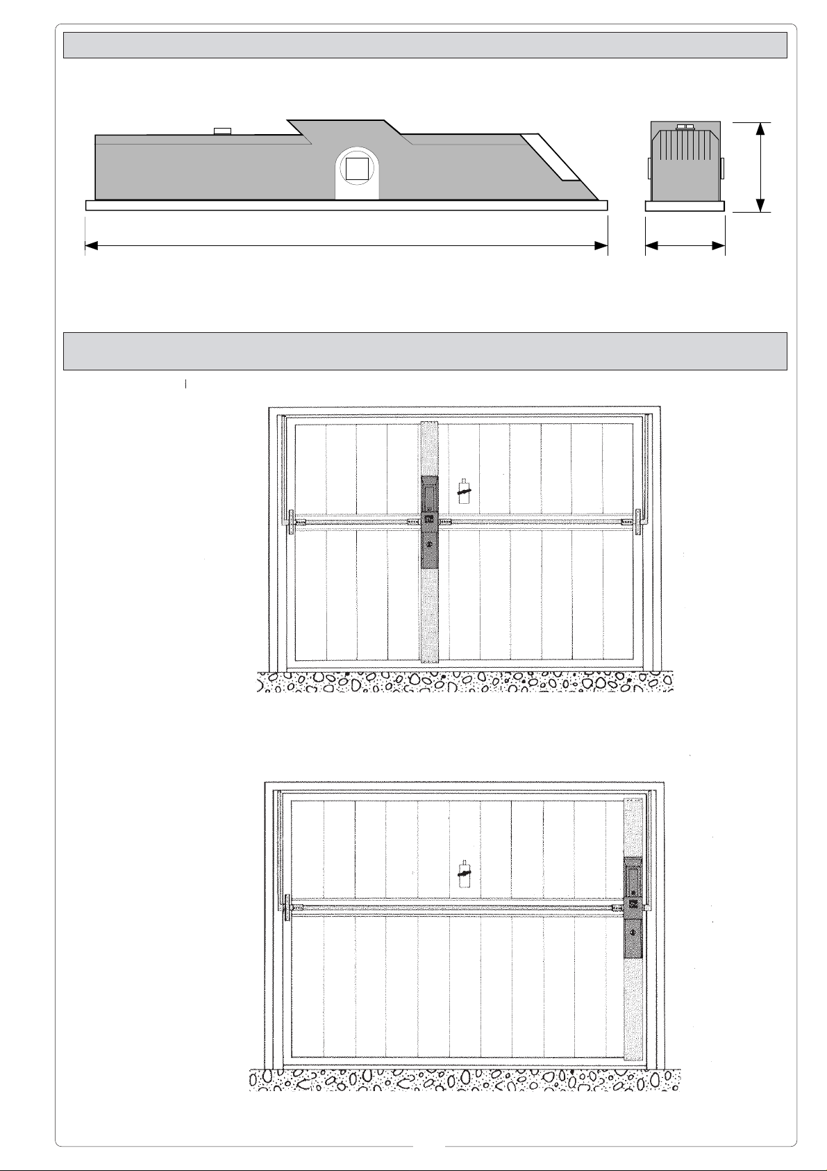
Controllare:
- il movimento della
porta sia uniforme
lungo tutta la corsa
evitando attriti o
giochi tra cuscinetti di
scorrimento (1) e
carrucole(2);
- la struttura della porta
basculante sia
adeguatamente
robusta e le cerniere
(3) siano efficienti
(basculante snodata)*;
- il percorso dei cavi
elettrici secondo le
disposizioni di
comando e sicurezza
(vedi Impianto tipo).
* Con basculante
snodata richiedere i
bracci snodati E 783
Check the following:
- the movement of the
door must be smooth
from the fully-open to
the fully-closed
positions, with no
friction or play between
the bearings (1) and the
pulleys (2);
- the door itself must be
sufficiently solid and the
hinges (3) must be
efficient (articulated
overhead door)*;
- the electrical wiring
path according to the
position of the control
and safety instruments
(see Installation type).
* Articulated doors
require E 783 articulated
arms
Vérifier:
- le mouvement de la
porte soit uniforme
sur toute la longueur
de la course en
évitant des
frottements ou des
jeux entre les paliers
de glissement (1) et
les poulies (2);
- la structure de la
porte basculante soit
suffisamment robuste
et que les charnières
(3) soient efficientes
(basculante articulée)*;
- le parcours des
câbles électriques
selon les dispositions
de com-mande et de
sécurité (voir installation type).
* Si la porte basculante
est du type articulée,
demander les bras
articulés E 783
Kontrollieren:
- die Torbewegung
während der gesamten
Laufzeit gleichmäßig
ausgeführt wird und ob
Reibungen oder Spielräume zwischen
Gleitla-gern (1) und
Laufrollen (2) auftreten;
- die Struktur des
Schwingtors entsprechend robust ist und die
Scharniere (3) leistungsfähig sind
(Gelenk-schwingtor)*;
- die elektrischen Kabel
gemaß den Antriebsund Sicherheitsvorschriften (siehe Standardanlage).
* Für Gelenk-Schwingtore die Gelenkarme E
783 anfordern
Controlar:
- el movimiento de la
puerta sea uniforme a
lo largo de toda la
carrera, evitando
roces o juegos entre
los cojinetes de deslizamiento (1) y las
poleas (2);
- la estructura de la
puerta basculante sea
suficientemente fuerte
y las bisagras (3)
adecuadas (basculante articulada)*;
- el recorrido de los
cables eléctricos
según las disposiciones de mando y
seguridad (véase
Instalación estándar).
* Con basculante
articulada pedir los
brazos articulados
E783
1 2 3
4
Page 5
PRIMA DELL'INSTALLAZIONE ... -
VOR DEN INSTALLATION ÜBERPRÜFEN
BEFORE INSTALLING .....
... - ANTES DE INSTALAR EL AUTOMATISMO...
- AVANT D'INSTALLER L'AUTOMATISME .....
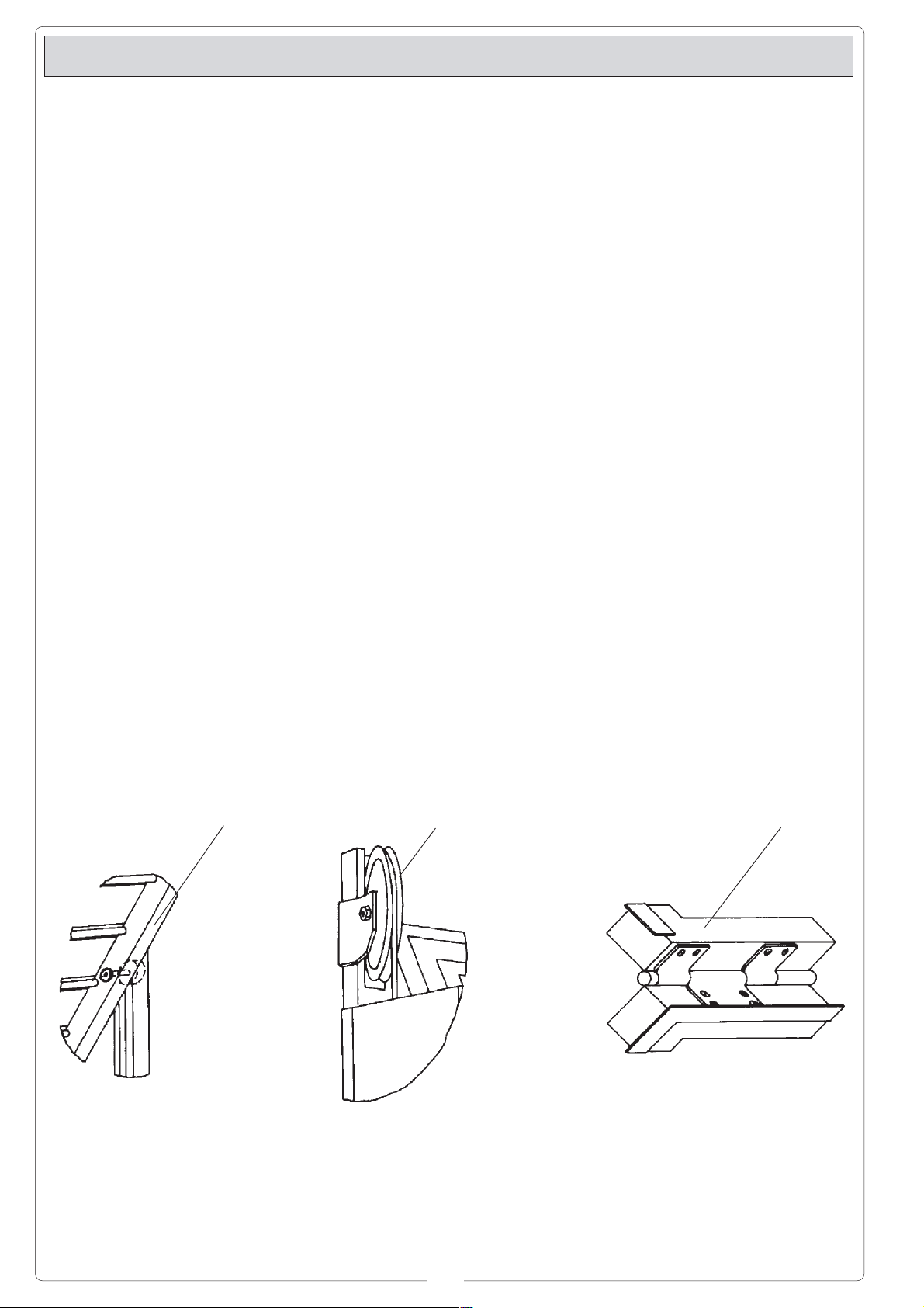
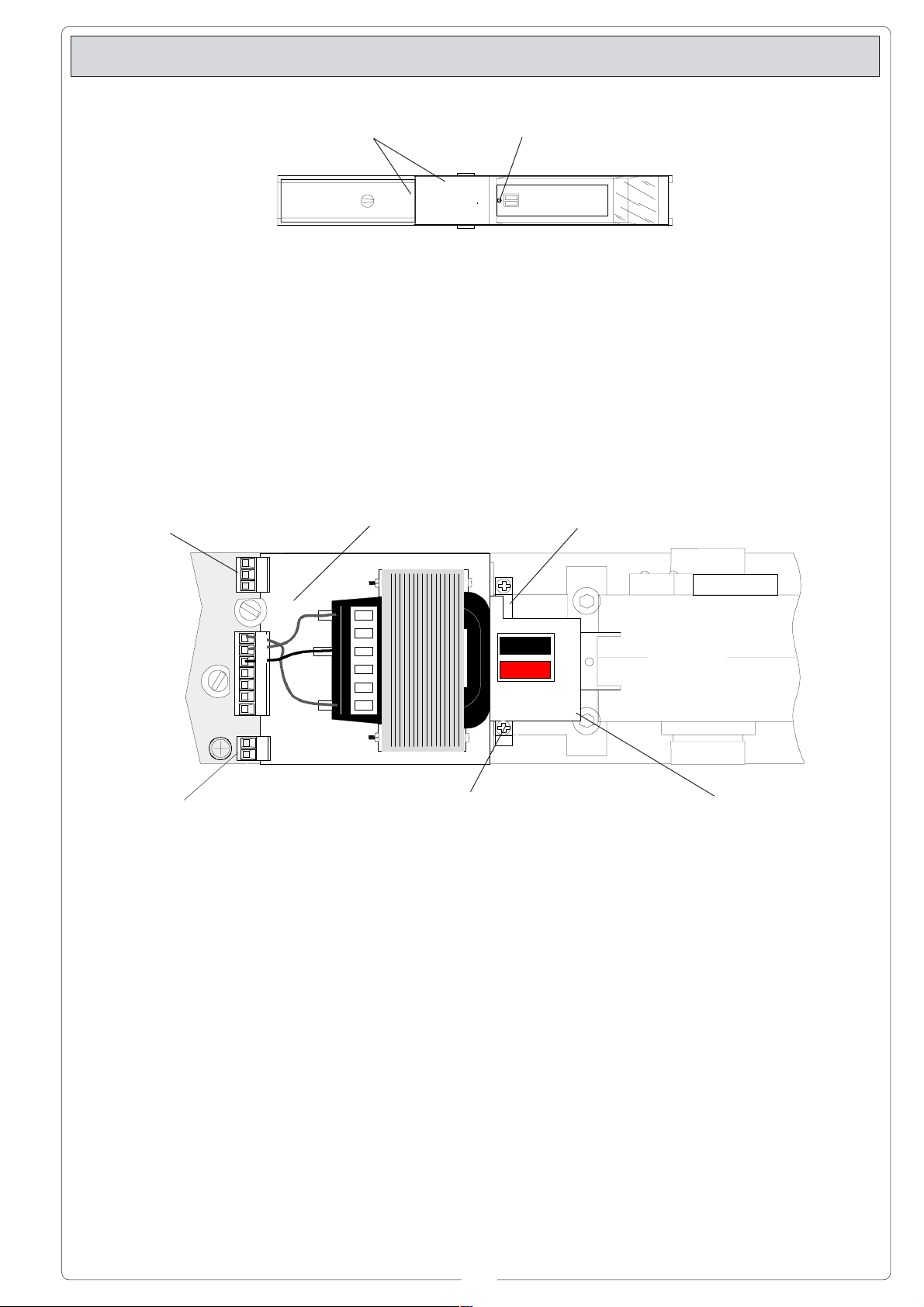
- Svitare la vite posta
sotto i pulsanti ed
estrarre i due coperchi.
Morsettiera motoriduttore
Gearmotor terminal board
Plaque à bornes motoréducteur
Klemmleiste Getriebemotor
Caja de conexiones para
motorreductores
Coperchio
Cover
Couvercle
Deckel
Tapa
- Unscrew the screw
located below the
pushbuttons and
remove the two covers.
Quadro elettrico
Control panel
Armoire électrique
Schalttafel
Cuadro eléctrico
- Desserer la vis qui
se trouve sous les
boutons-poussoirs et
retirer les deux
couvercles.
Vite
Screw
Vis
Schraube
Tornillo
- Die unter den beiden
Tasten befindliche
Schraube lösen Wund
die beiden Deckel
entfernen.
Condensatore
Capacitor
Condensateur
Kondensator
Condensafor
- Desenroscar el
tornillo colocado bajo
los pulsadores y
extraer las dos tapas.
W V U
L1TL2TCT
0 12 24
FA F
Morsettiera microinterrutore di stop in
apertura
Stop microswitch terminal board during opening
Plaque à bornes microcontact d'arrêt en
ouverture
Klemmleiste Mikroschalter Stop beim Öffnen
Caja de conexiones microinterruptor de
parada durante apertura
- Togliere l'innesto
delle morsettiere
contrassegnate con
le di-citure F-FA e UV-W, il condensatore, allentare le due
viti a croce per
estrarre il quadro
elettrico e le due viti
ad incasso
esagonale per
- Detach the
connection blocks
marked "F-FA and UV-W", the capacitor,
loosen the two crossheaded screws and
remove the control
panel. Loosen the two
socket-head screws
and remove the
motor.
estrarre il motore.
1234
Vite a croce
Cross-headed screw
Vis à croix
Kreuzschlitzschraube
Tornillo a estrella
- Enlever la partie qui
assure la connexion
avec la plaque à
bornes portant les
indications F-FA et
U-V-W et ôter le
condensateur. Desserer les deux vis à
croix pour retirer
l'armoire élec-trique
et les deux vis à
encastrement hexagonal pour enlever
le moteur.
Motore
Motor
Moteur
Motor
Motor
Vite ad incasso esagonale
Socket-head screw
Vis à encastrement hexagonal
Inbusschraube
Tornillo a encastre hexagonal
- Das mit der Beschriftung F-FA und U-VW versehene Klemmenleiste-Steckmodul und den
Kondensator entfernen. Dann die
beiden Kreuzschlitzschrauben losschrauben, um die
Schalttafel zu
entfernen und die
beiden Inbusschrauben losschrauben,
um den Motor
herauszu-ziehen.
- Quitar el acoplamiento de las caja
de bornes marcada
con F-FA y U-V-W, el
con-densador,
desenro-scar los
dos tornillos a
estrella para extraer
el cuadro eléctrico y
los dos tornillos a
encastre hexagonal
para sacar el motor.
5
Page 6
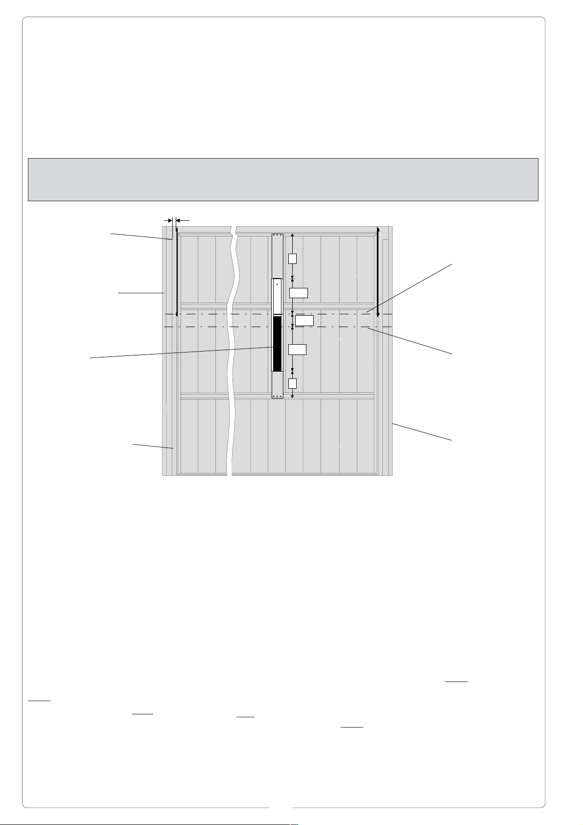
Esempio di applicazione su porta
basculante a contrappesi (H fino a 2400
mm) avente spazio
utile tra braccio porta
e carter del contrappeso di minimo 15
mm, con motore
applicato
centralmente.
Example of application
on counterweightbalanced door (height
up to 2400 mm) with a
net distance between
the door arm and the
counterweight casing
of at least 15 mm;
motor fitted laterally.
Exemple
d’application sur
porte basculante à
rail vertical (H jusqu’à
2400 mm) avec
espace utilisable
entre le bras de la
porte et le carter du
rail vertical non
inférieur à 15 mm et
moteur appliqué au
centre.
Installationsbeispiel:
Gelenkschwingtor mit
Gegengewichten (H bis
zu 2400 mm) und
zentral installiertem
Motor mit einem
Nutzabstand von
mindestens 15 mm
zwischen Torarm und
Gegengewichtskasten
(Leibung).
Ejemplo de aplicación
en puerta basculante
por contrapesos (H
hasta 2400 mm) con
espacio útil entre
montante de la hoja y
cárter de la puerta
non inferior a 15 mm,
con motor aplicado
centralmente.
Applicazione base/guida e staffe/prolunga -
Application base/guide et étriers/rallonge -
Aplicación base/guía y estribos/extensiones
Braccio porta
Door arm
Bras de la porte
Torarm
Brazo puerta
Carter contrappeso
Counterweight casing
Carter rail vertical
Gegengewichtskasten
Cárter contrapeso
Base-guida
Base-guide
Base-guide
Führungsschienen-Basis
Base-guía
Montante verticale dell'anta
Door upright
Montant vertical du vantail
Vertikaler Torpfosten
Montante vertical de la hoja
Min. 15 mm
Installation base/guide and anchor bracket/extension
Montage der Führungsschienen/basis und Verlängerungsbügel
Asse braccio porta
A
Axis of door arm
Axe bras de la porte
Torarm-Achse
Eje brazo puerta
300
110
Asse motore
380
Axis of motor
Axe du moteur
Motor-Achse
Eje motor
B
Staffa-prolunga
Anchor bracket/
extension
Etrier-rallonge
Verlängerungsbügel
Estribo-extension
- Abbassare completamente l'anta,
riportare nella
stessa le misure
indicate facendo
riferimento all'asse
inferiore del braccio
porta. Inserire le due
staffe-prolunga nalla
base-guida facendole fuoriuscire da
quest'ultima riportando le quote A e B
e fissarle
centralmente all'anta
mediante viti o
tasselli.
Nota: per l'installazio-
ne laterale, posizionare le due staffeprolunga
sovrapponen-dole al
montante verticale
dell'anta.
- Completely lower the
gatewing and mark
the gatewing with the
indicated measurements (in reference
to the lower axis of
the door arm). Install
the two anchor
bracket/extensions
onto the motor base/
door guide so that
they protude rom the
motor base/door
guide at distances A
and B. Fasten the
extensions to the
centre of the
gatewing. Use screws
or screw anchors.
Note: when the motor
is laterally installed,
superimpose and
mount the two anchor
bracket/extensions
directly onto the
vertical stanchion of
the
gatewing.
- Baisser la porte
complètement et
reporter sur celle-ci
cotes indiquées en
se référant à l'axe
inférieur du bras de
la porte. Introduire
les deux étriersrallonge dans la
base-guide en les
faisant dépas-ser de
celle-ci et en
reportant les cotes
A et B. Fixer ensuite
les étriers au centre
de la porte en
utilisant des vis ou
des chevilles.
N.B: pour
l'installation latérale,
positionner les deux
étriers-rallonge en
les superposants au
montant vertical de
la porte.
- Das Tor ganz
herunterbewegen und
die angegebenen
Maße auf den Torflügel
übertragen, dabei die
untere Torarm- Achse
als Bezugspunkt
nehmen. Die beiden
Verlängerungsbügel in
die Führungsbasis
einsetzen und den
Maßen A und B
entsprechend vorstehen lassen. Dann die
V erlängerungs-bügel
mit Schrauben bzw.
Dübeln an der
Torblattmitte
befestigen.
Anm.: bei seitlicher
Installation die beiden
Verlänger ungsbügel
an den vertikalen TorRahmenprofilen befestigen.
- Bajar completamente la puerta, marcar
en la misma las
medidas indicadas
tomando como referencia el eje inferior
del brazo puerta.
Introducir los dos
estribos-extensiones en la base-guía
hacién-dolos sobresalir de esta última
las distancias A y B
y fijarla en el centro
de la puerta mediante tornillos y tacos.
Nota: para la
instalación lateral,
colocar los dos
estribos-extensiones sobreponiéndolos al montante
vertical de la puerta.
6
Page 7
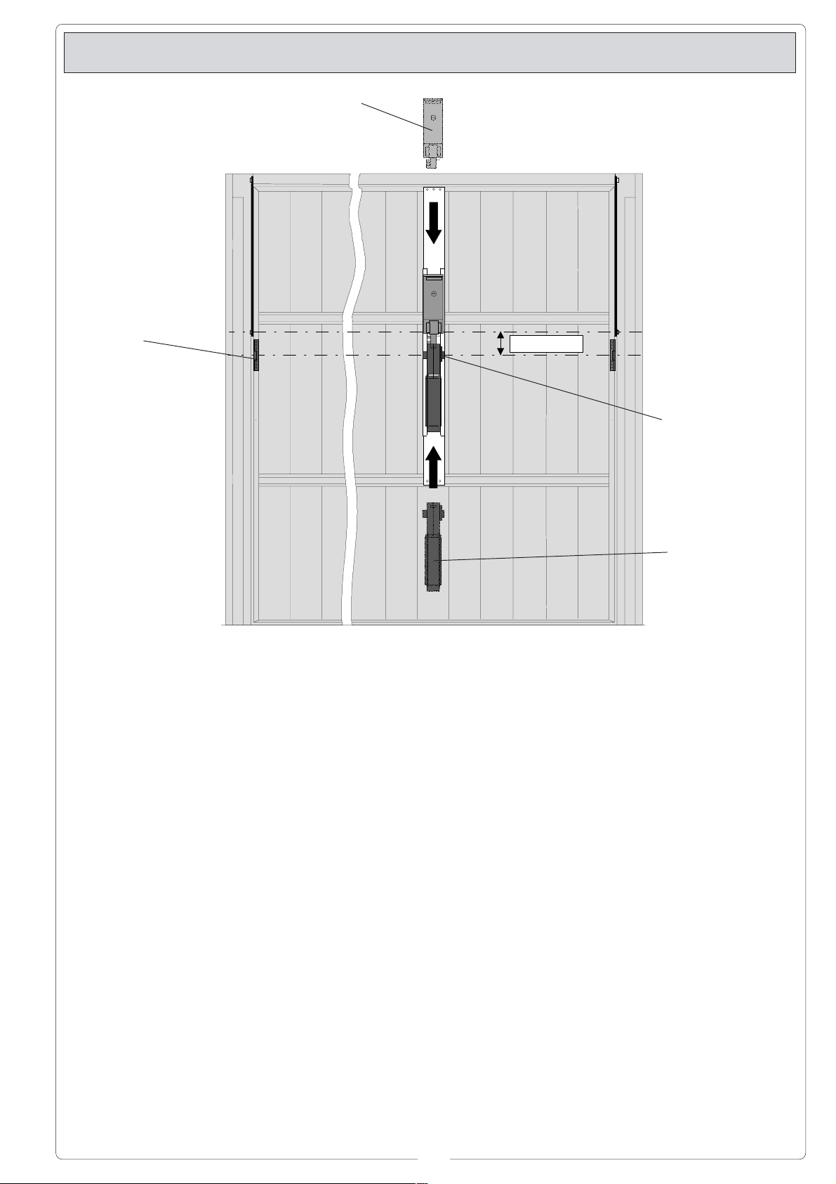
Application moteur et renvois -
Rinvio
Transmission system
Renvoi
Vorgelege
Reenvío
Applicazione motore e rinvii -
Installation Motor und Vorgelege
Quadro elettrico
Control panel
Armoire électrique
Schalttafel
Cuadro eléctrico
Application motor and transmision system
- Aplicación motor y reenvios
110 mm
Albero motore
Motor shaft
Arbre moteur
Antriebeswelle
Arbol motor
- Inserire il motore
nella base-guida e
nel senso della
freccia facendo
corrispondere l'asse
dell'albero motore
con l'asse dei 110
mm e bloccarlo con
le due viti ad incasso esagonale.
Inserire il quadro
elettrico come
indicato dalla
freccia, bloccarlo
con le due viti a
croce.
- Collegare le morsettiere contrassegnate
con le diciture F-FA
e U-V-W.
- Successivamente,
fissare i rinvii ai
montanti verticali
dell'anta ed in asse
con l'albero motore.
- Install the motor on
the motor base/door.
Be sure the motor
points in the direction
shown by the arrow,
and be sure the motor
shaft is alignes with
the 110 mm. axis.
Fasten the motor with
the two socket-head
screws provided.
Install the control
panel in the directions
shown by the arrow
and fasten the panel
with the two crossheaded screws
provided.
- Connect the terminal
boards marked with
the wording F-FA and
U-V-W.
- Then, fasten the
transmissions to the
vertical stanchions of
the gatewing. Make
sure the
transmissions are
aligned with the motor
shaft.
- Introduire le moteur
dans la base-guide
en respectant le
sens de la flèche et
en faisant
correspondre l'axe
de l'arbre moteur
avec l'axe de 110
mm. Bloquer ensuite
le moteur en
utilisant les deux vis
à encastrement hexagonal. Introduire
l'armoire électrique
de la manière reportée sur la figure
(suivre la flèche),
puis la bloquer en
utilisant les deux vis
à croix.
- Connecter les
plaque à bornes
portant les
indications F-FA et
U-V-W.
- Fixer ensuite les
renvois sur les montants verticaux du
vantail de façon à ce
qu’ils soient sur le
même axe que
l'arbre moteur.
- Den Motor in
Pfeilrichtung in die
Führungsbasis
einsetzen und die
Antriebswellenachse
mit der 110-mmAchse
übereinstimmen. Den
Motor mit zwei
Inbusschrauben befestigen. Die Schalttafel
in Pfeilrichtung
einfügen und mit den
beiden Kreuzschlitzschrauben
befestigen.
- Das mit der Beschriftung F-FA und
U-V-W gekennzeichnete Klemmenbrett
anschließen.
- Dann die Vorgelege
achsengleich mit der
Antriebswelle an den
beiden vertikalen TorRahmenprofilen
befestigen.
Motore
Motor
Moteur
Motor
Motor
- Introducir el motor
en la base-guía y en
el sentido de la
flecha haciendo
coincidir el eje del
árbol motor con el
eje de los 110 mm y
bloquearlo con los
dos tornillos a
encastre hexagonal.
Introducir el cuadro
eléctrico como
indica la flecha, bloquearlo con los dos
tornillos a estrellas.
- Conectar las caja de
bornes marcada con
F-F A y U-V-W.
- Posteriormente fijar
los renvíos a los
montantes
verticales de la
puerta y en eje con
el árbol motor.
7
Page 8
Applicazione del braccio telescopico dritto E785A -
Application du bras télescopique droit E785A -
Aplicación del brazo telescópico recto E785A
Application of the E785A straight telescopic arm
Montage des geraden Teleskoparms E785A
Fig. 4
Anta
Wing
Vantail
Tor
Hoja
- Alzare completamente l'anta, rilevare la misura "B" (fig.
4) e da questa
accorciare sia il
braccio sia il tubo di
30 mm. Fissare il
tubo e le staffe
angolari mediante la
vite, la rondella e il
dado in dotazione.
Applicare il tubo
esternamente e
possibilmente più
vicino al braccio
porta e fissarlo
mediante vite o
robusta saldatura
(fig. 5).
B
Rinvio
Transmission system
Renvoi
Vorgelege
Renvío
- Raise the door to the
fully-open position
and measure the
length of “B” (see fig.
4). Both the arm and
the tube should be
trimmed to 30 mm
less than the length of
"B". Use the nut,
washer and bolt
supplied with the unit
to secure the tube
and the angle
brackets. Fit the tube
externally, as close
as possible to the
door arm, and fasten
with screw or by
welding (see fig. 5).
Fig. 5
Staffe angolari
Angle brackets
Etriers
Eckbügeln
Estribos angular
- Lever le vantail
complètement,
relever la cote “B”
(fig. 4) et, en tenant
compte de cette
cote, raccourcir le
bras et le tube de
façon à ce qu'ils
soient 30 mm plus
courts. Fixer le tube
et l’étriers en
utilisant la vis, la
rondelle et l’écrou
fournis avec le
matériel. Appliquer
le tube à l’extérieur
et si possible le plus
près du bras de la
porte et le fixer au
moyen de l’écrou ou
d’une soudure solide
(fig. 5).
Braccio porta
Door arm
Bras de la porte
Torarm
Brazo puerta
- Das Tor ganz
hochheben und das
Maß “B” (Abb. 4)
abmessen und sowohl
den Arm als auch das
Rohr um 30 mm
kürzen. Das Rohr und
die Eckbügeln mit der
mitgelieferten
Schraube, der
Unterlegscheibe und
der Mutter befestigen.
Das Rohr außen
anbrin-gen, nach
Möglichkeit näher am
Torarm, und mit der
Mutterschraube befe-
stigen oder fest
anschweißen (fig. 5).
Tubo
Tube
Tube
Rohr
Tubo
Rondella
Washer
Rondelle
Unterlegscheibe
Arandela
-
Levantar completa-
Dado
Bolt
Ecrou
Mutter
Tuerca
Vite
Screw
Ecrou
Schraube
Tornillo
mente la hoja, medir
la cota “B” (fig.4) y a
partir da este punto
acortar tanto el
brazo como el tubo
30 mm. Fijar el tubo
y los estribos
angular mediante el
tornillo, la arandela
y la tuerca
suministrados.
Aplicar el tubo en la
parte externa y lo
más cercano posible
al brazo puerta, y
fijarlo mediante
tornillo o soldadura
resistente (fig.5).
Applicazione E781A -
Braccio
Arm
Bras
Arm
Brazo
Boccola
Bushing
Douille
Buchse
Casquillo
Albero quadro
Panel shaft
Arbre à section carrée
Vierkantwellen
Eje cuadrado
Application of E781A accessories
L1
- Application du Kit E781A -
L2
Fig. 7
Camma
Cam
Came
Nocken
Leva
Montage E781A
Fig. 6
Rinvio
Transmission system
Renvoi
Vorgelege
Renvío
Grano
Screw
Vis
Stift
Tornillo
Albero quadro
Panel shaft
Arbre à section carrée
Vierkantwellen
Eje cuadrado
- Aplicación E781A
Tubo
Tube
Tube
Rohr
Tubo
Boccola
Bushing
Douille
Buchse
Casquillo
Braccio
Arm
Bras
Arm
Brazo
8
Page 9

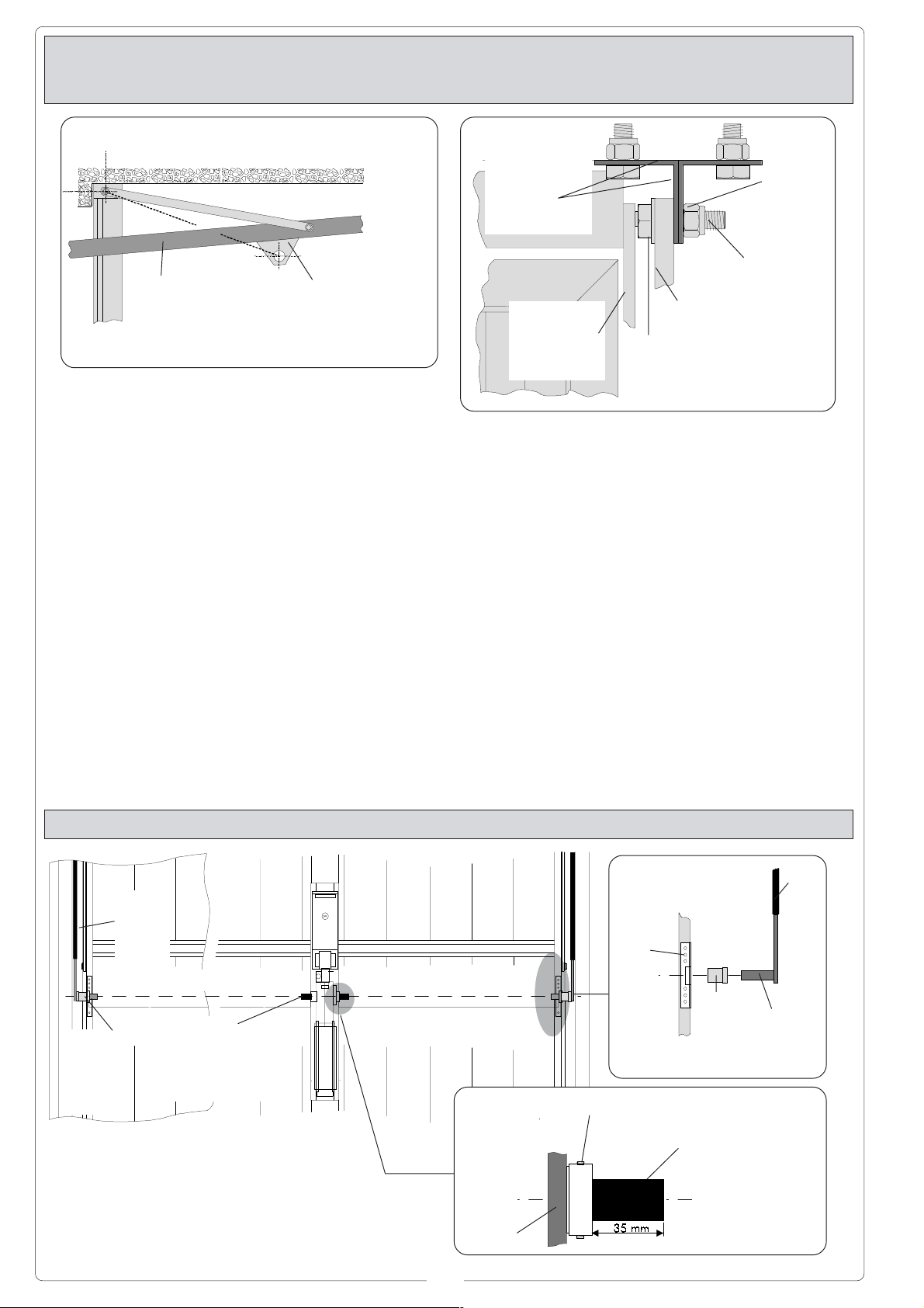
- Inserire gli alberi
quadri al motore
lasciandoli sporgere di 35 mm e
bloccarli con i grani
di fissaggio posti
sull'albero motore
(fig. 6). Lubrificare
le boccole e inserirle nei rinvii. Tagliare il tubo di trasmissione 10 mm più
corto delle distanze
L1 ed L2 (distanza
tra il profilo della
boccola e il profilo
dell'albero motore).
Lubrificare e
inserire il braccio
nel tubo e collegare
quest'ultimo alla
boccola e al rinvio
come da fig. 7.
- Fit the square
transmission shafts to
the motor so that they
protrude by 35 mm.
Anchor the transmission shafts by
tightening the screws
on the motor drive
shaft (see fig. 6).
Lubricate the bushings
and insert them into
the tran-smission
system. Cut the tube
so that it is 10 mm
shorter than the
distances L1 and L2
(i.e. the distance
between the face of
the bushing and the
edge of the motor
drive shaft). Lubricate
the arm and
insert into the tube.
Connect the tube to
the bushing and the
transmission system
as shown in fig. 7.
- Introduire les arbres
à section carrée sur
le moteur en les
laissant dépasser de
35 mm, puis les
bloquer avec les vis
de fixation placées
sur l’arbre moteur
(fig. 6). Lubrifier les
douilles et les
introduire dans les
renvois. Couper le
tube de transmission
de façon à ce qu’il
soit 10 mm plus
court par rapport aux
distances L1 et L2
(distance entre le
profil de la douille et
le profil de l’arbre
moteur). Lubrifier et
introduire le bras
dans le tube, puis ce
dernier à la douille et
au renvoi de la
manière repré-sentée
sur la fig. 7.
- Die Vierkantwellen so
in den Motor
einsetzen, daß sie 35
mm herausragen und
dann mit den an der
Motor-welle
befindlichen
Befestigungsstiften
festklemmen (Abb. 6).
Buchsen schmieren
und in die Vorgelege
einsetzen. Das Tran-
smissionsrohr um 10
mm kürzer als die
Abstände L1 und L2
(Abstand zwischen
Buchsenprofil und
Motorwellenprofil)
schneiden. Arm und in
das Rohr einsetzen,
dann den Arm gemäß
Abb. 7 mit der Buchse
un dem Vorgelege
verbinden.
- Introducir los ejes
cuadrados en el
motor dejando que
sobresalgan 35 mm,
y bloquearlos con
los tornillos de
fijación colocados
en el eje motor
(fig.6). Engra-sar los
casquillos y
encajarlos en los
reenvíos. Acortar el
tubo de transmisión
10 mm menos de las
distancias L1 y L2
(distancia entre el
perfil del casquillo y
el perfil del eje
motor). Engrasar y
encajar el brazo en
el tubo y unir este
ultimo al casquillo y
el reenvío como se
indica en la fig.7.
Nota per l'installazione laterale del motore -
Anmerkung für die seitliche Installation des Motors -
5 mm
Le fasi di montaggio
sono uguali a quelle
precedentemente
descritte con le sole
differenze seguenti:
- applicare la baseguida sovrapponendola al montante
verticale dell'anta.
- usufruire di una
confezione di
E 781A applicandolo
al montante verticale opposto al
motore.
The procedure is
identical to that
described previously,
though with the
following exceptions:
- fit the base-guide over
the door upright.
- use the E 781A set,
which should be fitted
to the upright on the
side opposite the
motor.
Note for lateral installation of the motor -
Nota para la instalación lateral del motor
5 mm
Les phases sont
identiques à celles
décrites. Les seules
différences sont les
suivantes:
- appliquer la baseguide en la
superposant au
montant vertical du
vantail.
- utiliser un kit E 781A
et l’appliquer sur le
montant vertical
opposé au moteur.
9
Die Installationsvorgänge stimmen im
wesentlichen mit den
schon beschriebenen
überein. Anders ist nur,
daß:
- die
FührungsschienenBasis am vertikalen
Torpfosten montiert
wird.
- Ein Montageset
E 781A
verwenden und an
dem dem Motor
gegenüber-liegenden
vertikalen Pfosten
anbringen.
Installation latérale du moteur
Las fases son iguales
a las ya descritas,
con estas únicas
diferen-cias:
- aplicar la base-guía
superponiéndola al
montante vertical de
la hoja.
- utilizar un lote de
E 781A aplicándolo
al montante vertical
opuesto al motor.
Page 10

SCHEDA BASE -
MOTHERBOARD
ZEXOA
- CARTE BASE -
GRUNDPLATINE
- TARJETA BASE
COMPONENTI PRINCIPALI
1 Morsettiere di collegamento
2 Fusibile di linea 5A
3 Fusibile accessori 1.6A
4 Innesto scheda radiofrequenza AF (vedi tabella pag. 16)
5 Pulsante memorizzazione codice radio
6 Dip-switch "selezione funzioni"
7 Trimmer T.L.: regolazione tempo lavoro
8 Trimmer TCA: regolazione tempo di chiusura automatica
9 LED di segnalazione codice radio
10 Lampada illuminazione ambiente (lampada di cortesia)
11 Limitatore di coppia motore
Attenzione! Prima di ogni operazione di connessione
o sconnessione delle schede, bisogna togliere la
tensione di linea all’impianto.
MAIN COMPONENTS
1 Terminal block for external connections
2 5A line fuse
3 1.6A accessories fuse
4 Socket AF radiofrequency board (see table page 16)
5 Radio-code save button
6 "Function selection" dip-switch
7 Trimmer T.L.: operating time adjustment
8 Trimmer TCA: automatic closing time adjustment
9 Radio-code LED
10 Lamp for illumination of installation area
11 Motor torque limiter
Caution! Before doing an y connection or
disconnection work on the board, the system must be
disconnected from the power supply.
COMPOSANTS PRINCIPAUX
1 Plaque à bornes pour les branchements
2 Fusible de ligne 5A
3 Fusible accessoires 1.6A
4 Branchement carte radiofréquence AF (voir tableau p.16)
5 Bouton mise en mémoire code radio
6 Dip-switch "sélection fonction"
7 Trimmer T.L.: Réglage du temps de fonctionnement
8 Trimmer TCA: Réglage Temps de fermeture automatique
9 LED de signalisation code radio
10 Lampe d'éclairage du lieu
11 Limiteur de couple moteur
Attention! Avant de brancher ou de débrancher les
cartes, couper le courant de l’installation.
GB
F
I
1
5
21
4
9
10
1234
6
8
7
3
2
11
HAUPTKOMPONENTEN
1 Anschluss-Klemmenleiste
2 5A-Sicherung Leitungs
3 1.6A-Sicherungen Zubehörs
4 Steckanschluß Funkfrequenze-Platine AF (sehen Tabelle
Seite 16)
5 Knöpfe zum Abspeicher der Radiocode
6 "Funktionswahl" dip-switch
7 Trimmer T.L.: Einstellung Laufzeit
8 Trimmer TCA: Einstellung Zeiteinstellung
Schließautomatik
9 LED Kontrolleuchte zur Anzeige von Radiocode
10 Raumbeleuchtung
11 Drehmomentbegrenzer des motor
Achtung! Jedesmal, wenn die Karten angeschlossen
oder ausgebaut werden, muß der Strom an der
Anlage abgeschaltet werden.
D
COMPONENTES PRINCIPALES
1 Caja de bornes para las conexiónes
2 Fusible de linea 5A
3 Fusible accesorios 1.6A
4 Conexión tarjeta radiofrecuencia AF (vedas tabla pág.16)
5 Botone de memorización del código radio
6 Dip-switch "seleción función"
7 Trimmer TL: Regulación tiempo trabajo
8 Trimmer TCA: Regulación cierre automático
9 Indicador luminoso código radio
10 Lámpara para la iluminación del ambiente
11 Limitador de par motor
¡Atencion! Antes de cualquier operación de conexión
o desconexión de las tarjetas hay que quitar la
tensión de línea a la instalación.
10
E
Page 11

ITALIANO
DESCRIZIONE TECNICA QUADRO COMANDO ZEXOA
Il quadro comando va alimentato sui
morsetti L1 e L2 ed è protetto in
ingresso con fusibile di linea da 5A.
I dispositivi di comando sono a bassa
tensione (24V), e sono protetti con
fusibile da 1.6A. La potenza
complessiva degli accessori a 24V,
non deve superare i 20W.
Dotato di un limitatore di coppia
motore a 4 posizioni. Tale sistema è
esente da usura, insensibile agli sbalzi
di temperatura e non necessita di
alcuna manutenzione.
Sicurezza
Le fotocellule possono essere
collegate e predisposte per:
-
Riapertura in fase di chiusura,
fotocellule rilevando un ostacolo durante
la fase di chiusura delle ante, provocano
l'inversione di marcia fino alla completa
apertura, dispositivo collegato sui
morsetti 2-C1;
-
Stop totale
, arresto del portone
le
escludendo l'eventuale ciclo di
chiusura automatica; per riprendere il
movimento bisogna agire sulla
pulsantiera o sul radiocomando (1-2);
Altre funzioni
-
Chiusura automatica
. Il
temporizzatore di chiusura automatica
si attiva a finecorsa apre o a fine
tempo lavoro in apertura. Il tempo
prefissato regolabile, é comunque
subordinato dall'intervento di eventuali
accessori di sicurezza e si esclude
dopo un intervento di «stop» totale o
in mancanza di energia elettrica;
-
Funzione a "uomo presente"
.
Funzionamento del cancello mantenendo premuto il pulsante (esclude il
funzionamento del radiocomando); Si
abilita quando il trimmer T.L. è regolato
al minimo;
Tipo di comando
:
- apre-chiude per pulsante e
trasmettitore;
- apre-stop-chiude-stop per pulsante e
trasmettitore.
Accessori collegati in serie
-
Lampada di cortesia
(25W).
Lampada che illumina la zona di
manovra, dopo un comando di
apertura rimane accesa per un tempo
fisso di 3 minuti e 30 secondi;
Finecorsa apre
-
. Arresto della porta
con l'ausilio del microinterruttore
durante la fase di apertura, collegare il
micro ai morsetti F-F A;
Accessori opzionali
-
Lampada spia porta aperta
(3W
max.). Lampada che segnala la
posizione di apertura della porta
basculante, si spegne a fine tempo
lavoro di chiusura (10-5).
-
Elettroblocco
(24V -15W max.).
Collegato ai morsetti EB-EB;
- Lampeggiatore di movimento
(25W
max.), collegato ai morsetti W-E.
Regolazioni
- T empo lavoro;
- Tempo chiusura automatica.
Attenzione! Prima di intervenire
all’interno dell’apparecchiatura,
togliere la tensione di linea.
ENGLISH
TECHNICAL DESCRIPTION ZEXOA CONTROL PANEL
The control panel is powered across
terminal L1 and L2, and is protected
by a 5A fuse on the main power line.
Control systems are powered by low
voltage and protected with by a 1.6A
fuse.
The total power consumption of 24V
accessories must not exceed 20W.
Equipped with a 4 position torque
limiter. This system is not subject to
wear and tear, is not sensitive to
changes of temperature and does
notrequire any maintenance.
Safety
Photocells can be connected to obtain:
-
Re-opening during the closing cycle
the photocells on detecting an
obstacle while closing the door, cause
the movement direction to be reversed
until opening is complete (2-C1);
-
Total stop
, shutdown of door
movement without automatic closing; a
pushbutton or radio remote control
must be actuated to resume movement
(1-2);
Other functions
Automatic closing
. The automatic closure timer comes on at the end of the
run or at the end of the opening time.
The changeable set time is also subject to modifications due to the intervention of possible saf ety accessories.
This does not happen following a complete “stop” command or in the event of
a power cut;
- "
Operator present
" function: Gate
operates only when the pushbutton is
held down (the radio remote control
system is deactivated). It is activated
when the T.L. trimmer is set to the
minimum;
,
Type of command
:
- open-close by button and transmitter;
- open-stop-close-stop by button and
transmitter.
Accessories connected in series
-
Courtesy Light
(25W). A light that
illuminates the manoeuvring zone;
after an opening command, the light
remains on for a fixed time of 3
minutes and 30 seconds;
-
Limit switch opening
. The door stops
with the help of the microswitch during
the opening phase, connect the
microswitch to terminal blocks F-FA;
Optional accessories
-
Open gate pilot lamp
(3W max.). This
is a light that indicates the garage-type
door's open position and turns off
when the gate activates the closing
end-stop (terminals 10-5);
-
Electric lock
(24V-15W max.),
connect it to terminal blocks EB-EB;
-
Flashing signal light
when gate is in
motion (25W max.), connect it to
terminal blocks W-E;
Adjiustments
- Operating time;
- Automatic closure time.
Caution! Disconnect the unit
from the main power lines before
carrying out any operation inside the
unit.
11
Page 12

FRANÇAIS
DESCRIPTION TECHNIQUE ARMOIRE DE COMMANDE ZEXOA
L'armoire de commande doit être
alimentée avec une tension de 230V
sur les bornes L1 et L2 et elle est
protégée en entrée par un fusible de
ligne de 5A.
Les dispositifs de commande sont à
basse tension et protégés avec fusible
de 1.6A. La puissance total des
accessoires à 24V, ne doit pas
dépasser 20W.
Equipé d’un limiteur de couple moteur
a 4 positions. Ce système ne s’use
pas, est insensible aux sautes de
température et ne nécessite d’aucun
entretien.
Sécurité
Il est possible de brancher des
photocellules et de les programmer
pour:
-
Reouverture en phase de fermeture,
en détectant un obstacle durant la
phase fermeture des vantaux, les
photocellules provoquent l’inversion de
marche jusqu’à la ouverture compléte,
(2-C1);
-
Stop total
désactivation d'un éventuel cycle de
fermeture automatique; pour activer de
nouveau le movement, il faut agir sur
, arrét du portail et
les bouton-poussoir ou sur la
radiocommande (1-2);
Autres fonctions
-
Fermeture automatique
comptage du temps de fermeture
automatique démarre quand le
microcontact de “fin de course
ouverture” s’active ou à la fin du cycle
d’ouverture. Le temps préétabli
réglable dépend néanmoins de
l’intervention d’accessoires de sécurité
éventuels et est exclu après un arrêt
“stop” total ou en cas de coupure de
courant;
-
Function "homme mort"
Fonctionnement du portail en
maintenant appuyé le bouton-poussoir
(exclut la fonction de la
radiocommande). Il s'active quand le
compensateur T.L. est réglé au
minimum;
Type de commande
- ouvre-ferme pour bouton et
émetteur;
- ouvre-stop-ferme-stop pour bouton et
émetteur.
Accessoires branchés en série
-
Lampe passagge
. Le
.
:
(25W). Lampe qui
illumine la zone de manoeuvre, après
une commande d’ouverture elle reste
allumée pour une durée fixe de 3
minutes et 30 secondes;
Interrupteur fin de course ouverture
Arrêt de la porte à l’aide du
microcontact durant la phase
d’ouverture, brancher le microcontact
aux bornes F-FA;
Accessoires en option
-
Voyant porte ouverte
Lampe qui signale la position
d’ouverture de la porte basculante,
elle s’éteint à la fin du cycle de
fermeture (bornes 10-5);
-
Serrure électrique
la brancher aux bornes EB-EB;
-
Clignotant de mouvement
max.), la brancher aux bornes W -E.
Réglages
- Temps de fonctionnement;
- Temps de fermeture automatique.
Attention! Avant d’intervenir à
l’intérieur de l’appareillage, couper la
tension de ligne.
(3W max.).
(24V-15W max.),
(25W
.
DEUTSCH
Die Steuergeräts wird mit einer
Spannung über die Klemmen L1 und
L2 gespeist und ist am Eingang mit
einer 5A-Hauptsicherung. Die
Steuerungen erfolgen mit Niederspannung und geschützen enie 1.6ASicherung. Die Gesamtleistung des
24-V-Zubehörs darf 20W nicht
überscheiten.
Ausgestattet mit einem 4-stufigen
Drehzahlbegrenzer für den Motor. Das
System ist verschleißfrei,
unempfindlich gegenüber
Temperaturschwankungen und
wartungsfrei.
Sicherheitsvorrichtungen
Die Lichtschranken können für
folgende Funktionen angeschlossen
bzw. vorbereitet werden:
-
Wiederöffnen
Lichtschranken erf assen beim
Schließen der Torflügel ein Hindernis
und lösen die Umkehrung der
Laufrichtung bis zum vollständigen
Öffnen aus (2-C1);
-
Totalstop
Tores mit Auschluß eventueller
Schließautomatik: Fortsetzung des
beim Schließen, die
, sofortiger Stillstand des
TECHNISCHE BESCHREIBUNG SCHALTTAFEL ZEXOA
Torlaufs über Drucktaster- bzw .
Funksteuerung (1-2);
Andere funktionen
-
Schließautomatik
automatischen Schließen schaltet sich
beim Endanschlag Öffnen ein, oder
wenn die Arbeitszeit vom Öffnen
abgelaufen ist. Die einstellbare,
vorgegebene Zeit ist aber in jedem Fall
dem Zuschalten eventueller
Sicherheitsvorrichtungen
untergeordnet und wird nach einem
„Stop“ oder bei Stromausfall
ausgeschlossen.
-
Funktion "Bedienung vom
Steuerpult"
tasterbetätigung (Funkfernsteuerung
ausgeschlossen). Wird dann
eingeschaltet, wenn der T.L. auf das
Minimum gestellt ist;
. Torbetrieb durch Druck-
Befehlsarten
- Öffnen-Schließen für Druckknopf und
Sender;
- Öffnen-Stop-Schließen-Stop für
Druckknopf und Sender.
Serienmäßig angeschlossenes
Zubehör
. Der Timer vom
:
-
Torbeleuchtung
Befehl zum Öffnen des Tors gegeben
worden ist, bleibt das Licht, das den
Manöverbereich am Tor beleuchtet, für
eine vorgegebene Zeit von 3 Minuten
und 30 Sekunden eingeschaltet;
(25W). Nachdem der
- Endanschlag des Öffnungsvorganges
rend des Öffnungsvorganges in jeder
gewünschten Position durch Bedienung des Mikroschalters; den Mikro an
die Klemmen F-FA anschließen;
Extrazubehör
max.). Diese Kontrollampe zeigt an,
daß das Schwingtor offen ist und
schaltet sich ab, wenn die Schließzeit
abgelaufen ist (Klemmen 10-5).
mit den Klemmen EB-EB verbinden.
Klemmen W-E.
Einstellungen
- Laufzeit;
- Zeit für das automatische Schließen.
. Blockierung des Tores wäh-
Kontrollampe bei geöffnetem Tor
Elektrische Verriegelung
Blinkleuchte
Achtung! Das Gerät vor
Eingriffen im inneren spannungsfrei
schalten.
(25W max.), mit den
24V-15W,
(3W
12
Page 13

ESPANOL
DESCRIPCIÓN TÉCNICA CUADRO DE MANDO ZEXOA
El quadro de mando se alimenta en
los bornes L1 y L2 está protegido en
entrada con fusible de línea a 5A.
Los dispositivos de mando son a baja
tensión y está protegidos por fusible a
2A. La potencia total de los accesorios
a 24V, no debe superar lo 20W.
Equipado con un limitador de par
motor de 4 posiciones. Dicho sistema
no sufre desgastes, es insensible a los
saltos de temperatura y no requiere
ningún mantenimiento.
Seguridad
Las fotocélulas pueden estar
conectadas y predispuestas para:
Reapertura en fase de cierre,
-
las
fotocélulas detectan un obstáculo
durante la cierre de la hojas, causando
la inversión del movimiento hasta que
se abre totalmente, (2-C1);
Parada total
-
, parada de la puerta
excluyendo el posible ciclo de cierre
automático; para reactivar el
movimiento es preciso actuar en el
teclado o en el mando s distancia
(1-2);
microinterruptor de final de carrera de
apertura o al final del ciclo de
apertura. El tiempo prefijado regulable
está subordinado al accionamiento de
posibles accesorios de seguridad y se
desconecta después de una “parada”
total o si se corta la energía eléctrica;
Función a "hombre presente".
Funcionamiento de la puerta
manteniendo pulsada la tecla (excluye
la función del mando a distancia). Se
activa cuando el trimmer T.L. está
regulado en el mínimo;
Tipo de mando:
- abrir-cerrar para botón y transmisor;
- abrir-parada-cerrar-parada para
botón y transmisor.
Accesorios conectados en serie
Luz de cortesía
-
(25W). Lámpara que
ilumina la zona de maniobra; tras un
mando de apertura permanece
encendida por 3 minutos y 30
segundos;
- Final de carrera apertura
. Paro de la
puerta con la ayuda del
microinterruptor durante la apertura;
conecte el micro a los bornes F-FA;
posición de apertura de la puerta
basculante, se apaga al final del
tiempo de cierre (bornes 10-5);
Electrocerradura 24V - 15W max.
-
,
conéctela a los bornes EB-EB;
Lámpara intermitente de movimiento
(25W max.), conéctela a los bornes WE.
Regulaciones
- Tiempo de trabajo;
- Tiempo de cierre automático.
Otras funciónes
Cierre automático
-
. La cuenta del
tiempo para el cierre automático
comienza cuando se activa el
Accesorios opcionales
Lámpara indicadora de puerta abierta
(3W máx.). Lámpara que señala la
¡Atención! Antes de actuar
dentro del aparato, quitar la tensión
de línea.
13
Page 14

COLLEGAMENTI ELETTRICI -
ELECTRICAL CONNECTIONS
-
BRANCHEMENTS ELECTRIQUE
-
ELEKTRISCHE ANSCHLÜSSE
-
CONEXIONES ELECTRICAS
Selettore a chiave
Keyselector
C
Sélecteur à clé
Schlüssel-Wählschalter
Selector a llave
N.O.
Contatto radio e/o pulsante apre-chiude
Contact radio and/or pushbutton controlled for
open-close
Contac radio et/ou poussoir ouvre-ferme
Kontakt Funkgerät und/oder Taste
Öffnen-Schließen
Contacto radio y/o pulsador de
apertura-cierre
Lampada spia
Open gate pilot lamp
24V
3W max.
Lampe porte ouverte
Kontrollampe bei
geöffnetem Tor
Indicador luminoso de
10
5
*
puerta abierta
Lampeggiatore
Flashing
Clignotant
Blinkleuchte
Lámpara
230V
25W max.
W
E
Alimentazione 230V (a.c.)
230V (a.c.) power supply
Alimentation 230V (c.a.)
Stromversorgung
230V Wechselstrom
Alimentación 230V
L2
L1
(a.c.)
+ -
*
2
+ -
c
n.o.
n.c.
7
Pulsante stop (n.c.)
*
2
1
Stop-Taste (Ruhekontakt)
Stop button (n.c.)
Poussoir stop (n.c.)
Pulsador stop (n.c.)
Accessori 24V a.c. (max. 20W)
24V accessories
a.c. (20W max.)
Alimentation 24V c.a. (max. 20W)
Stromversorgung 24V
11
10
*
EB
EB
Wechselstrom (max. 20W)
Alimentación 24V a.c. (máx.
20W)
24V
15W max.
Elettroblocco
Electric block
Serrure électrique
Elektroschloß
Electrocceradura
* Accessori non compresi nel kit.
* Accessories not included in the kit.
* Accessoires pas compris dans le kit.
* Extrazubehör
* Accesorios no incluidos en el kit.
I contatti 1-2 e 2-C1
sono contatti normalmente chiusi (
se non fossero utilizzati devono essere
cortocircuitati.
N.C.);
Contacts 1-2
N.C. contacts. These
are
contacts must be
connected together if
thei are not used.
and
2-C1
W5C1721 10EBEB11EL1 L2
Les contacts 1-2 et 2C1 sont des contacts
normalement fermée
N.F.). Si on ne utilise
(
pas, ces contacts
doivent être courtcircuités.
14
Die Kontakte 1-2
C1 sind normalweise
gesch-lossene Kontakte
(N.C.), werden sie nicht
für eventuelle weitere
Vorrichtungen
verwendet, müssen sie
Kurzgeschlos-sen
werden.
und
2-
Antenna
Atenna
Antenne
Antennenanschluß
Antena
Los contactos
C1 están normalment
cerrados (
se utilizan de deben
cortocicuitar.
1-2 y 2-
N.C.), si no
Page 15

SELEZIONI FUNZIONI -
SELECTION OF FUNCTIONS
- SÉLECTION FONCTIONS -
FUNKTIONSWAHL
- SELECCIÓN DE LAS FUNCIONES
ITALIANO
1 ON Chiusura automatica attivata; (1 OFF disattivata)
2 ON "Apre-stop-chiude-stop" con pulsante (2-7) e
radiocomando (scheda AF inserita) attivato;
2 OFF "Apre-chiude" con pulsante (2-7) e radiocomando
(scheda AF inserita) attivato;
ENGLISH
1 ON Automatic closure enabled; (1 OFF disabled)
2 ON "Open-stop-close-stop" with button (2-7) and
radio control (AF board inserted) enabled;
2 OFF "Open-close" con pulsante (2-7) with button (2-7)
and radio control (AF board inserted) enabled;
DEUTSCH
1 ON Schließautomatik zugeschaltet; (1 OFF
ausgeschlossen)
2 ON "Öffnen-Stop-Schließen-Stop" mit Druckknopf (2-7)
und Fernsteuerung (Karte AF eingesteckt) zugeschaltet;
2 OFF "Öffnen-Schließen" mit Druckknopf (2-7) und
Fernsteuerung (Karte AF eingesteckt) zugeschaltet;
21
21
ON
1234
FRANÇAIS
1 ON Fermeture automatique activé; (1 OFF éteinte)
2 ON "Ouvre-stop-ferme-stop" avec bouton (2-7) et
commande-radio (carte AF insérée) activé;
2 OFF "Ouvre-stop" avec bouton (2-7) et commande-radio
(carte AF insérée) activé;
ESPANIOL
1 ON Cierre automático activado; (1 OFF desactivado)
2 ON "Abrir-stop-cerrar-stop" con botoón (2-7) y
radiocontrol (tarjeta AF conectada) activado;
2 OFF "Abrir-cerrar" con botón (2-7) y radiocontrol
(tarjeta AF conectada) activado;
OFF
ITALIANO
Trimmer T.L.
REGOLAZIONI -
= Regolazione tempo lavoro da un minimo di
A
DJUSTMENTS
- RÉGLAGE -
15 secondi a un massimo di 80 secondi.
(Nota: regolando al minimo il tempo lavoro si abilita la
funzione «uomo presente»).
Trimmer T.C.A.
= Regolazione tempo di chiusura automatica da un minimo di 1 secondo a un massimo di 120 secondi.
ENGLISH
Trimmer T.L.
= Adjusts of operating time (min.15”,
max.80”).
(Note: the "operator present" function is activated by setting
the operating time to the minimum).
Trimmer T.C.A.
= Adjusts automatic closing time (min.1”,
max.120”)
DEUTSCH
E
INSTELLUNG
- RÉGULACIÖN
T.C.A.
21
T.L.
REGOLAZI ONE TRIMMERS
TRIMMERS A DJUSTMENT
RÉGLAGE TRIMMERS
EINTELLUNG TRIMMERS
REGULACIÓN TRIMMERS
FRANÇAIS
Trimmer T.L.
= Réglage du temps de fonctionnement (min.
15”, max. 80”).
Note: la fonction "homme mort" s'active en réglant le temps
de fonctionnement au minimum).
Trimmer T.C.A.
= Réglage du temps de fermeture
automatique (min. 1”, max. 120”).
ESPANIOL
Trimmer T.L.
= Laufzeit mit mindestens 15" und höchstens
80” eingestellt werden kann.
(Hinweis: Wenn die Betriebsdauer auf ein Minimum gestellt
wird, wird die Funktion "Bedienung vom Steuerpult"
eingeschaltet).
Trimmer T.C.A.
= Timer, auf dem die Verzögerung für das
automatische Schließen mit mindestens 1” und höchstens
120” eingestellt werden kann.
Trimmer T.L.
= Régulación tiempo de trabajo (min. 15”,
max. 80”).
(Nota: regulando en el mínimo el tiempo de trabajo, se
activa la función "hombre presente").
Trimmer T.C.A.
= Régulación cierre automático (min. 1”,
max. 120”).
15
Page 16

LIMIT ATORE DI COPPIA MOTORE -
DREHMOMENTBEGRENZER DES MOTORS
MOT OR TORQUE LIMITER
-
LIMIT ADOR DE PAR MOTOR
-
LIMITEUR DE COUPLE MO TEUR
Per variare la coppia
motrice, spostare il
faston indicato (con
filo di colore nero) su
una delle 4 posizioni;
1 min. - 4 max.
INSTALLAZIONE DEL RADIOCOMANDO -
To vary the motor
torque, move the
indicated faston (with
black string) to one of
the four positions:
1=min, 4=max
2143
1234
RADIO CONTROL INSTALLATION
INSTALLATION DER RADIOSTEUERUNG
Pour varier le couple
du moteur, déplacer
le connecteur
indiqué (fil de
couleur noire) sur
l'une des 4 positions;
1 min. - 4 max.
CT 230V
24V12V 0
-
INSTALACIÓN DEL RADIOMANDO
Zur Änderung des
Motor-Drehmoments
den angegebenen
Faston (mit scharzem
Kabel) auf eine der 4
Stellungen positionieren: 1 min. - 4 max.
1234
-
INSTALLATION DE LA RADIOCOMMANDE
Para variar el par
motor, desplazar el
faston indicado (con
hilo de color negro)
hasta una de las 4
posiciones; 1 mín. - 4
máx.
ITALIANO
PROCEDURA
A. inserire una
scheda AF.
B. codificare il/i
trasmettitore/i.
C. memorizzare la
codifica sulla
scheda base.
A
La schedina AF deve essere inserita
OBBLIGA TORIAMENTE in assenza di
tensione.
The AF board should ALWAYS be
inserted when the power is off.
La carte AF doit OBLIGATOIREMENT
être branchée en l’absence de
tension.
Vor Einschieben der Karte die
Stromzufuhr UNBEDINGT abschalten.
La tarjeta AF se debe montar
OBLIGATORIAMENTE en caso de
falta de corriente.
ENGLISH
PROCEDURE
A. insert an
AF card.
B. encode
transmitter/s.
C. store code in the
motherboard.
INSERIMENTO SCHEDA AF -
EINSTECKEN DER KARTE AF-
FRANCAIS
PROCEDURE
A. placer une carte
AF.
B. codifier le/s
émetteur/s.
C. mémoriser la
codification sur la
carte base.
AF BOARD INSERTION
MONTAJE DE LA TARJETA AF
SCHEDA "AF"
"AF" BOARD
CARTE "AF"
KARTE «AF»
TARJETA «AF»
SCHEDA BASE
MOTHERBOARD
CARTE DE BASE
BASISKARTE
TARJETA BASE
Frequenza / MHz
Frequency / MHz
Frequence / MHz
Frequenz / MHz
Frecuencia / MHz
FM 26.995 AF130 TFM
FM 30.900 AF150 TFM
AM 26.995 AF26 TOP
AM 30.900 AF30 TOP
AM 433.92
DEUTSCH
PROZEDUR
A. Stecken Sie eine
Karte AF.
B. Codieren Sie den/
die Sender.
C. Speichern Sie die
Codierung auf der
Grundplatine.
- INSTALLATION DE LA CARTE AF
Scheda radiofrequenza
Radiofrequency board
Carte radiofréq ue n c e
Funkfrequenz-Platine
Tarjeta radiofrecuencia
AF43S / AF43SM TAM / TOP
AF43SR ATOMO
ESPANOL
PROCEDIMIENTO
A. introducir una
tarjeta AF.
B. codificar el/los
transmisor/es.
C. memorizar la
codificación en la
tarjeta base.
Trasm ett it ore
Transmitter
Emetteur
Funksender
Transmisor
16
Page 17

B
CODIFICA TRASMETTITORI -
CODIERUNG DER SENDER -
TOP
QUARZATI
TRANSMITTER ENCODING
- QUARTZ
CODIFICACIÓN TRANSMISORES
- AU QUARTZ
- QUARTZGENAUE
- CODIFICA TION DES EMETTEURS
- CUARZO
PROCEDURA COMUNE DI CODIFICA
T262M-T264M-T2622M
T302M-T304M-T3022M
1.segnare un codice (anche per archivio)
2.inserire jumper codifica J
3.memorizzarlo
4.disinserire jumper J
ANLEITUNGEN ZUR CODIERUNG
T262M-T264M-T2622M
T302M-T304M-T3022M
1.Ordnen Sie einen Code zu (auch für das
Archiv).
2.Schalten Sie den Codierungs-Jumper J ein.
3.Speichern Sie den Code.
4.Schalten Sie den Jumper J wieder aus.
PROCEDIMIENTO COMÚN DE CODIFICACIÓN
T262M-T264M-T2622M
T302M-T304M-T3022M
1.marcar un código (también para el
archivo)
2.conectar un jumper codificación J
3.registrar el código
4.desconectar jumper J
T2622M - T3022M
1° codice/
Code
P1 P2
/codigó
code/
J
code/
STANDARD ENCODING PROCEDURE
T262M-T264M-T2622M
T302M-T304M-T3022M
1.assign a code (also on file)
2.connect encoding jumper J
3.register code
4.disconnect jumper J
codice/
codice
1.
/codice/
codice
P1
P2
3.
premere in sequenza P1 o P2 per registrare il
codice; al decimo impulso un doppio suono
confermerà l'avvenuta registrazione
Press P1 or P2 in sequence in order to register
the code; at the tenth pulse, a double beep will
confirm that registration has occurred
appuyer en séquence sur P1 ou P2 pour
mémoriser le code; à la dixième impulsion, une
double sonnerie confirme que le code a été
mémorisé
Drücken Sie nacheinander P1 oder P2, um den
Code zu speichern. Nach dem zehnten Impuls
signalisiert ein doppelter Piepton, daß der Code
gespeichert worden ist.
oprimir repetidamente P1 ó P2 para registrar el
código; con el décimo impulso un doble sonido
señalará que el registro se ha efectuado.
PROCEDURE COMMUNE DE CODIFICATION
T262M-T264M-T2622M
T302M-T304M-T3022M
1.taper un code (également pour les
archives)
2.placer un cavalier de codification J
3.mémoriser le code
4.enlever le cavalier J
/codice
OFF
ON
P1=OFF
2.
J
P2=ON
4.
J
2° codice/
P1
P2
J
code/
code/
T264M - T304M
P1=CH1 - P2=CH2
P3=CH3 - P4=CH4
P1 P2
P3 P4
Code
P1=CH1
P2=CH2
/codigó
OFF
ON
P3=CH1
P4=CH2
J
P1 P2
fig. A
T262M - T302M
La prima codifica deve essere effettuata mantenendo i jumper
posizionati per i canali 1 e 2 come da fig. A; per eventuali e successive impostazioni su canali diversi vedi fig. B
The first encoding operation must be carried out whilst keeping the
J
jumpers positioned for channels 1 and 2 as per fig. A; see fig. B for
any subsequent settings on different channels.
La première codification doit être effectuée en maintenant les
cavaliers en position pour les canaux 1 et 2, comme d'après la fig.
A; pour des saisies successives éventuelles sur des canaux
différents, voir fig. B
Für die erste Codierung muß der Jumper auf den Kanälen 1 und 2
positioniert bleiben (siehe Abb. A). Für eventuelle weitere oder
spätere Einstellungen auf anderen Kanälen halten Sie sich bitte an
Abb. B.
La primera codificación tiene que efectuarse manteniendo los
jumper conectados para los canales 1 y 2 como se ilustra en la fig.
A; para planteamientos posteriores en canales distintos ver la fig. B
fig. B
P1=CH1 - P2=CH3
P1=CH1
P2=CH2
P1=CH3 - P2=CH2
P1=CH1 - P2=CH4
17
P1=CH3 - P2=CH4
Page 18

P1 P2
D
1 2 3 4
1 2 3 4 5 6 7 8 9 10
ATOMO
AT01 - AT02 - AT04
vedi foglio istruzioni inserito nella confezione
della scheda AF43SR
see instruction sheet inside the pack of AF43SR circuit card
voir les instructions qui se trouve dans l'emballage
de la carte AF43SR
Siehe Anleitungen, die der Packung beiliegen der Platine AF43SR
ver hoja de instrucciones adjunta en el embalaje
de la tarjeta AF43SR
T432M - T312M
impostare il codice sul dip-switch C e il canale su D (P1=CH1 e P2=CH2, impostazione di
default)
set the code to dip-switch C and channel to D (P1=CH1 and P2=CH2, default setting)
saisir le code sur le commutateur dip C et le canal sur D (P1=CH1 et P2=CH2, saisie de
défaut)
Stellen Sie den Code auf den Dip-Switch C und den Kanal auf D (P1=CH1 und P2=CH2;
Grundeinstellung).
plantear el código en el dip-switch C y el canal en D (P1=CH1 y P2=CH2, planteamiento
por defecto)
P1
1 2 3 4 1 2 3 4 1 2 3 41 2 3 4
CH1 CH2 CH3
CH4
C
P2
1 2 3 4 1 2 3 4 1 2 3 4 1 2 3 4
CH1 CH2 CH3
CH4
P1 P2
P3 P4
P1=CH1
P2=CH2
P3=CH3
P4=CH4
1 2 3 4 5 6 7 8 9 10
TAM
T434M - T314M
impostare solo il
codice
ne saisir que le code
plantear sólo el código
C
T432
T434
T438
vedi istruzioni su confezione
set code only
Stellen Sie nur den
Code ein.
vedi foglio istruzioni inserito nella confezione
see instruction sheet inside the pack
voir la notice d'instructions qui se trouve dans
l'emballage
Siehe Anleitungen, die der Packung beiliegen.
ver hoja de instrucciones adjunta en el embalaje
T432SA - T432S - T434MA
see instructions on pack
voir instructions sur
l'emballage
Siehe Anleitungen auf der
Packung.
ver instrucciones en el
embalaje
TFM
T132
T134
T138
T152
T154
T158
18
Page 19

C
MEMORIZZAZIONE CODICE -
SPEICHERN VOM CODE -
CODE STORAGE
MEMORIZACIÓN CÓDIGO
- MEMORISA TION DU CODE
ITALIANO
Tenere premuto il
tasto "PROG" sulla
scheda base, il led di
segnalazione lampeggia (vedi fig.1), con un
tasto del trasmettitore
si invia il codice, il led
rimarrà acceso a
segnalare l'avvenuta
memorizzazione
(fig.2).
N.B.: se in seguito si
vuol cambiare codice,
basta ripetere la
sequenza descritta.
Fig./Abb. 1
ENGLISH
Keep the "PROG" key
pressed on the base
card, the signal LED
will flash (see fig.1),
and with a key on the
transmitter the code is
sent, the LED will
remain lit to signal the
successful saving of
the code (figure 2).
N.B.: if you wish to
change the code on
your transmitters in
the future, simply
repeat the procedure
described above.
FRANCAIS
Appuyer sur la touche
"PROG" sur la carte
de base, le led de
signalisation clignote
(voir fig.1), avec une
touche du emetteur on
envoie le code, le led
reste allumé pour
signaler que la
mémorisation s'est
effectuèe (fig.2).
N.B.: si,
successivement, on
veut changer le code
des émetteur, il suffit
de répéter la
séquence décrite cidessus.
DEUTSCH
Drücken Sie die Taste
"PROG" auf der
Basiskarte und halten
Sie die gedrückt (LED
blinkt (siehe Abb.1),
mit einer Taste vom
Sender wird der Code
abgeschickt. Das LED
hört auf zu blinken
und bleibt an, sobald
das Speichern erfolgt
ist (Abb.2).
HINWEIS: bei
eventuell erwünschter
Sender codeänderung
ist der beschriebene
Vorgang zu
wiederholen.
ESPANOL
Mantener oprimida la
tecla "PROG" en la
tarjeta base, el led de
señalización parpadea
(mirar fig.1), con una
tecla del transmisor se
envía el código, el led
permanece encendido
para indicar que el
almacenamendo se
ha efectuado (fig.2).
Nota: si posteriormente se quisiera cambiar
el código de los
propios transmisores,
sólo hay que repetir la
secuencia descrita.
2143
LED acceso
Lit LED
LED allumé
LED Kontrolleuchte
LED encendido
PROG.
Scheda radiofrequenza AF
AF radiofrequency board
Carte radiofrèquence AF
Funkfrequenz-Platine AF
Tarjeta radiofrecuencia AF
LED intermittente
Flashing LED
LED clignotant
LED Aufblinkende
LED intermitente
Fig./Abb. 2
PROG.
2143
19
Page 20

COLLEGAMENTO ABBINATO -
ANSCHLUSSE P ARALLELGESCHALTETEN
CONNECTIONS COMBINED
-
CONEXIÓN ACOPLADOS
-
CONNEXIONS ACCOUPLÈS
Nel caso d'installazione di due motori,
collegare il primo
motoriduttore
(E600A) in parallelo
con il secondo
(E601), come da
schema raffigurato.
In the case of
installation of two
motors, connect the
first gearmotor
(E600A) in parallel
with the second
(E601).
En cas d'installation
de deux moteurs,
brancher le premier
motoréducteur
(E600A) en parallèle
avec le second
(E601), comme
d'après le schéma.
Quadro comando
Control panel
Armoire de commande
Schaltaffel
Cuadro de mando
EW
Wenn zwei Motoren
installiert werden
sollen, den ersten
Getriebemotor
(E600A) mit dem
zweiten (E601)
parallel schalten
(siehe Abbildung).
Para la instalación
de dos motores,
conecte el primer
motorreductor
(E600A) en paralelo
con el segundo
(E601), como
muestra el esquema.
Lampada di cortesia
Courtesy light
Lampe passegge
Torbeleuchtung
Luz de cortesía
E600A
2143
W
UV
Motore 1
Motor 1
Moteur 1
Motor 1
Motor 1
U V W K
Motore 2
Motor 2
Moteur 2
Motor 2
Motor 2
E601
20
Page 21

Regolazione microinterruttore di stop in apertura
Adjusting the stop microswitch for the aperture movement
Réglage du micro-interrupteur de stop dans la phase d'ouverture
Einstellung des Stop-Mikroschalters in der Öffnungsphase
Regulacion del microinterruptor de parada en la fase de apertura
Base-guida
Base-guide
Base-guide
Führungsschienen-Basis
Base-guía
- Portare l'anta a
circa 30 mm dall'apertura.
- Ruotare la camma
fino a far inserire il
microinterruttore e
avvitare la vite
posta sulla camma.
Microinterruttore
Microswitch
Micro-interrupteur
Mikroschalters
Microinterruptor
- Move the gatewing
to a distance of
approx. 30 mm from
the open position.
- Turn the cam until \
the microswitch is
activated and screw
the screw on the cam.
- Positionner le
vantail à environ 30
mm de l'ouverture
désirée.
- Tourner la came
jusqu’à ce que le
microcontact
s’enclenche et
visser la vis qui se
trouve dans la
came.
Camma
Cam
Came
Nocken
Leva
- Das Tor auf eine
Entfernung von ca. 30
mm von der gewünschten Öffnungsstellung bewegen.
- Den Nocken drehen,
bis der Mikroschlter
einrastet und die auf
dem Nocken
befindliche Schraube
befestigen.
- Llevar la puerta
aprox. a 30 mm de
la apertura.
- Gire la leva hasta
hacer entrar el
microinterruptor y
enrosque el tornillo
situado en la leva.
- Riposizionare i due
coperchi e avvitare
la vite posta sotto il
copriforo.
Coperchio -
Deckel
Cover
- Tapa
- Replace the two
covers and tighten
the screw located
below the holecover.
- Couvercle
- Remettre en place
les deux
couvercles et
visser la vis qui est
placée sous les
bouchon.
21
Vite -
Screw
- Vis
Schraube
- Tornillo
- Die beiden Revisionsdeckel wieder
anbrin-gen und die
unter den Tasten
befindliche
Schraube wieder
fest-schrauben.
- Volver a colocar las
dos tapas y
enroscar el tornillo
colocado debajo de
los tapón.
Page 22

Collaudi -
Testing
- Essais -
Betriebskontrollen
- Pruebas
- Far oscillare l'anta:
se non resta in
equilibrio in ogni
posizione, intervenire sui contrappesi
come segue:
motore applicato
centralmente.
Il peso del motore
va diviso e ripartito
nei due contrappesi
in modo equo;
motore applicato
lateralmente.
Il peso del motore
viene ripartito in
circa: 1/3 sul
contrappeso del
lato motore e 2/3 su
quello opposto.
Per le porte
basculanti a molle,
invece, spostare il
punto di attacco di
queste nel foro più
adatto.
- Move the door up
and down. If the door
does not remain in
each position, adjust
the counterweights
as follows:
central motor.
The weight of the
motor should be
equally distributed
between the counterweights.
One lateral motor.
The weight of the
motor should be
distributed as
follows: 1/3 on the
counterweight on the
motor side, 2/3 on
the opposite counterweight. For springbalanced doors,
move the anchor
point to the most
suitable hole.
- Faire basculer le
van-tail: si l’on
constate un
déséquilibre dans
chaque position,
intervenir sur les
rails verticaux de la
manière indiquée cidessus:
Moteur appliqué au
centre.
Le poids du moteur
doit être divisé et
réparti sur les deux
rails verticaux de
façon égale.
Moteur appliqué sur
le côté.
Le poids du moteur
doit être réparti de
la façon suivante: à
peu près 1/3 sur le
rail vertical du côté
moteur et 2/3 sur le
rail vertical opposé.
Pour les portes
basculantes à
ressorts, il faut
déplacer le point de
fixation de ces
ressorts dans le
trou le plus indiqué.
- Das Tor schwingen
lassen: wenn es nicht
in jeder Position im
Gleichgewicht bleibt,
folgendermaßen auf
die Gegengewichte
ein-wirken:
bei zentral
installiertem Motor
das Gewicht des
Motors halbieren und
gleichmäßig auf die
beiden
Gegengewichte
aufteilen;
bei seitlich
montiertem Motor
das Gewicht des
Motors ungefähr so
aufteilen: 1/3 auf das
an der Motorseite
befin-dliche
Gegengewicht und 2/
3 auf das der Motorseite
gegenüberliegende
Gegengewicht; Bei
Schwingtoren mit
Federn jedoch den
Verankerungspunkt
der Federn in die
geeigne-tere Bohrung
verlagern.
- Hacer oscilar la hoja:
si no queda en
equilibrio en todas las
posiciones, intervenir
sobre los contrapesos
de la siguiente
manera:
motor aplicado
central-mente.
El peso del motor se
divide y reparte en
los dos contrapesos
en partes iguales;
motor aplicado
lateralmente.
El peso del motor se
reparte
apróximativa-mente:
1/3 sobre el
contrapeso del lado
motor y 2/3 sobre el
opuesto; Para las
puertas basculantes
a muelles, por el
contrario, desplazar
el punto de fijación
de éstas al agujero
más adecuado.
Il gruppo non necessita di alcuna manutenzione specifica.
Solo come misura
cautelativa e in caso
di servizio intensivo
è opportuno controllare il cavo collegato
al motore e ingrassare le boccole, i
bracci e le guide dei
cuscinetti di scorrimento.
Manutenzioni periodiche -
Regelmaßige Wartung -
This unit requires no
specific maintenance.
However, as a
precaution and in
case of heavy-duty
service, it is advisable
to check the cable
connected to the
motor and to grease
the bushings, the
arms and the bearing
guides at regular
intervals.
Periodic maintenance
Mantenimiento periódico
Le groupe ne
nécessite aucun
entretien particu-lier.
Cependant comme
mesure de prudence
et en cas de service
intensif, il convient
de vérifier le câble
relié au moteur et de
graisser les douilles,
les bras et les
guides des paliers
de glissement.
22
- Entretiens périodiques
Die Anlage bedarf
keiner speziellen
Wartung. Nur als
Sicherheitsmaßnahme
und bei starker Beanspruchung und Dauerbetrieb sollte das am
Motor angeschlossene
Kabel geprüft und
Buchsen, Arme und
Gleitlager-schienen
geschmiert werden.
El conjunto no
necesita ningún
mantenimiento
específico. Sólo
como medida cautelar y en caso de uso
intensivo es conveniente controlar el
cable conectado al
motor y engrasar los
casquillos, los brazos
y las guías de los
cojinetes de deslizamiento.
Page 23

NOTE /
NOTES
/ NO TE /
HINWEIS
/ NOTA
23
Page 24

Tutti i dati sono stati controllati con la
massima cura. Non ci assumiamo comunque alcuna responsabilità per
eventuali errori od omissioni.
ASSISTENZA TECNICA
NUMERO VERDE
800 295830
EB
W
www.came.it
E-MAIL
CANCELLI AUTOMATICI
info@came.it
CAME CANCELLI AUTOMATICI S.P.A.
DOSSON DI CASIER (TREVISO)
(+39) 0422 4940 (+39) 0422 4941
All data checked with the maximum care.
However, no liability is accepted for any error
or omission.
SISTEMA QUALITÀ
CERTIFICATO
CAME LOMBARDIA S.R.L.______COLOGNO M. (MI)
(+39) 02 26708293 (+39) 02 25490288
CAME SUD S.R.L. ___________________NAPOLI
(+39) 081 7524455 (+39) 081 7529109
CAME (AMERICA) L.L.C.____________MIAMI (FL)
(+1) 305 5930227 (+1) 305 5939823
CAME AUTOMATISMOS S.A__________MADRID
(+34) 091 5285009 (+34) 091 4685442
CAME BELGIUM__________________LESSINES
(+32) 068 333014 (+32) 068 338019
Toutes les données ont été contrôlées
très soigneusement. Nous n’assumons
de toute façon aucune responsabilité pour
les erreurs ou omissions éventuelles.
Die Daten wurden mit höchster Sorgfalt
geprüft. Für eventuelle Fehler oder
Auslassungen übernehmen wir keine
Haftung.
CAME FRANCE S.A.____NANTERRE CEDEX (PARIS)
(+33) 01 46130505 (+33) 01 46130500
CAME GMBH________KORNTAL BEI (STUTTGART)
(+49) 07 11839590 (+49) 07 118395925
CAME GMBH____________SEEFELD BEI (BERLIN)
(+49) 03 33988390 (+49) 03 339885508
CAME PL SP.ZO.O______________WARSZAWA
(+48) 022 8365076 (+48) 022 8369920
CAME UNITED KINGDOM LTD___NOTTINGHAM
(+44) 0115 9210430 (+44) 0115 9210431
Todos los datos se han controlado con
la máxima atención. No obstante no nos
responsabilizamos de los posibles
errores u omisiones.
 Loading...