

CAME PST001, Twister, PST003 Installation Manual
PST001
TWISTER SERIES
TRIPOD
TURNSTILE
English
EN
INSTALLATION MANUAL
119G3040EN

WARNING!
Important instructions for the safety of people:
READ CAREFULLY!
Foreword
• Use of the products must be restricted to its intended use
(i.e. that for which it was expressly built for). Any other use is
to be considered dangerous. Came Cancelli Automatici S.p.A.
is not liable for any damage resulting from improper, wrongful
or unreasonable use • Keep these warnings with the installation and use manuals issued with the automated system.
Before installing
(preliminary check: in case of a negative
outcome, do not proceed before having
complied with the safety obligations)
• Make sure that the parts you intend to automate are in
good working order, and that they are properly balanced
and aligned. Also, make sure that proper mechanical stops
are already in place • If the operator will be installed at a
height of less than 2.5 m from the ground or other access
level, check whether you will need any protections and/or
warnings • Any gate leaves, fi tted with pedestrian entrances,
onto which you will install an operator, must have a blocking
mechanism when the gate is in motion • Make sure that the
opening of the automated gate is not an entrapment hazard
as regards any surrounding fi xed parts • Do not mount the
operator upside down or onto any elements that may fold
under its weight. If needed, add suitable reinforcements at
the points where it is secured • Do not install onto gates on
either an upward or downward slope (i.e. that are not on fl at,
level ground) • Check that any lawn watering devices will not
wet the gearmotor from the bottom up.
Installation
• Carefully section off the entire site to prevent unauthorised
access, especially by minors and children • Be careful when
handling operators that weigh more than 20 Kg (see installation manual). In such cases, employ proper weight handling
safety equipment • All opening commands (e.g. buttons, key
selectors, magnetic detectors, etc.) must be installed at least
1.85 m from the gate’s area of operation perimeter - or where
they cannot be reached from the outside of the gate. Also,
the direct commands (e.g. push button, or proximity devices,
etc.) must be installed at a height of at least 1.5 m and must
not be accessible to the public • All ‘maintained action’ commands, must be placed where the moving gate leaves, transit
areas and driveways are completely visible • If missing, apply a permanent label that shows the position of the release
mechanism • Before delivering to the client, verify that the
system is EN 12453 (impact test) standard compliant. Make
sure that the operator has been properly adjusted and that the
safety and protection devices, as well as the manual release
are working properly • Where necessary and in plain sight,
apply the Warning Sings (e.g. gate plate).
Special instructions and
advice for users
• Keep the gate’s area of operation clean and clear of any
obstacles. Trim any vegetation that may interfere with the
photocells • Do not allow children to play with the fi xed command devices, or in the gate’s area of operation. Keep any
remote control devices (i.e. transmitters) away from the children as well • Frequently check the system, to see whether
any anomalies or signs of wear and tear appear on the moving
parts, on the component parts, on the securing points, on the
cables and any accessible connections. Keep any joints (i.e.
hinges) lubricated and clean, and do the same where friction may occur (i.e. slide rails) • Perform functional tests on
photocells and sensitive edges, every six months. Keep glass
panels constantly clean (use a slightly water-moistened cloth;
do not use solvents or any other chemical products) • If the
system requires repairs or modifi cations, release the operator
and do not use it until safety conditions have been restored
• Cut off the power supply before releasing the operator for
manual openings. See instructions • Users are FORBIDDEN
to carry out ANY ACTIONS THAT THEY HAVE NOT BEEN
EXPRESSLY ASKED TO DO OR SO INDICATED in the manuals. Any repairs, modifi cations to the settings and extraordinary maintenance MUST BE DONE BY THE TECHNICAL
ASSISTANCE STAFF • On the periodic maintenance log, note
down the checks you have done.
Special instructions and
advice for all
• Avoid working near the hinges or moving mechanical parts
• Stay clear of the gate’s area of operation when in motion •
Do not resist the direction of movement of the gate; this may
present a safety hazard • At all times be extremely careful
about dangerous points that must be indicated by proper
pictograms and/or black and yellow stripes • When using
a selector or command in ‘maintained action’ mode, keep
checking that there are no people in the area of operation of
the moving parts. Do this until you release the command •
The gate may move at any time without warning • Always cut
the power when cleaning performing maintenance.

THIS PAGE LEFT INTENTIONALLY BLANK
THIS PAGE LEFT INTENTIONALLY BLANK

#
#
Pag.
2
- Manual code:
119G3040
119 G3 04 0 ver.
1.5
1.5 09/2010 © CAME cancelli automatici s.p.a. - The data and information reported in this installation manual are susceptible to change at any time and without obligation on CAME cancelli automatici s.p.a. to notify users.
ENGLISH
4.1 Turnstile
4 Description
2.1 Intended use
1 Legend of symbols
This symbol shows parts to be read carefully.
This symbol shows parts related to safety.
This symbol shows what to tell users.
The TWISTER electromechanical turnstile is designed to select transit flows in high-volume passage areas, and in highly frequented contexts like stadiums, airports, stations, public buildings and in any other places where high-volume flows need to be
regulated and/or selected
Any installation or use other than that shown in this manual is prohibited.
3 Reference Legislation
IMPORTANT SAFETY INSTRUCTIONS FOR INSTALLATION
WARNING: WRONG INSTALLATION MAY CAUSE SERIOUS INJURY, FOLLOW ALL INSTALLATION INSTRUCTIONS
THIS MANUAL IS EXCLUSIVELY MEANT FOR PROFESSIONAL INSTALLERS OR OTHER COMPETENT PERSONS
This product is designed and built by CAME Cancelli Automatici S.p.A. in compliance with the current safety legislation.
It allows passage in the desired direction of one person a time. By activating a command device, the mechanism releases the tripod
which rotates freely allowing people to pass through; the arms automatically return into place and the mechanism locks immediately
after a single passage, waiting for a new command.
The range includes:
001PST001 - Bi-directional electromechanical tripod turnstile AISI 304 steel with scotch-brite fi nishing, complete with ocntrol board,
transponder sensors and high-luminosity LED bi-directional traffi c light with display. Tripod automatic release in case of blackout.
Power: 230 V AC 50 / 60 Hz
Power Draw: 260 mA max
Insulation class: II
Protection rating: IP44
Weight: 60 Kg
The product being described herein complies with the following legislation: see compliance statement.
4.2 Technical Data
2 Intended use and limits
11
1
7
5
2
1
6
5
8
9
4
4
8
3
10
12
13
14
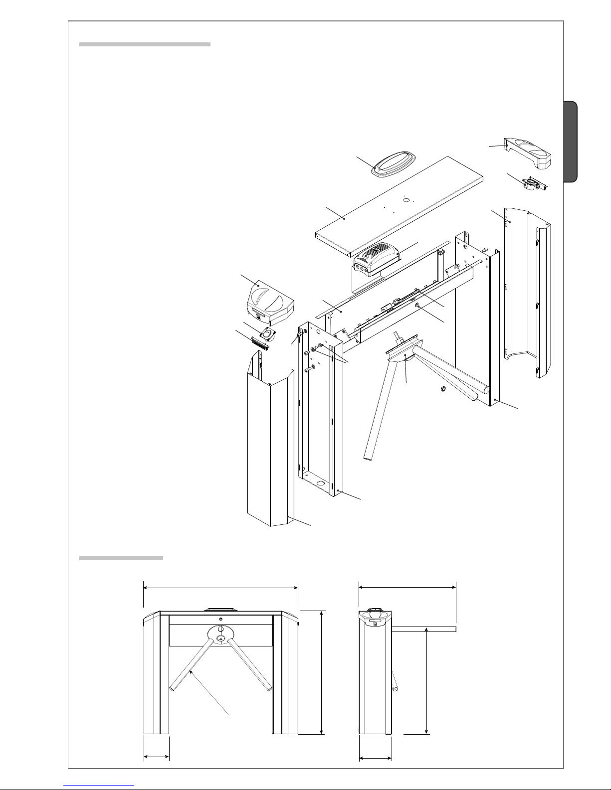
1200
950
750
250
195
ø 40
850
Pag.
3
-
Manual code
:
119G3040
119 G3 04 0 ver.
1.5
1.5 09/2010
© CAME cancelli automatici s.p.a. -
The data and information reported in this installation manual are susceptible to change at any time and without obligation on CAME cancelli automatici s.p.a. to notify users.
ENGLISH
4.4 Dimensions
4.3 Description of parts
Legs1.
Tripod2.
Steel body3.
Casing4.
Casing cover5.
Upper cover6.
Traffic-light with display7.
Transponder8.
Status display9.
Mechanism10.
Control panel11.
Cover lock12.
Screws and washers for fixing the legs13.
Screws for fixing the casing14.
EXIT
SWIMMING POOL
Pag.
4
- Manual code:
119G3040
119 G3 04 0 ver.
1.5
1.5 09/2010 © CAME cancelli automatici s.p.a. - The data and information reported in this installation manual are susceptible to change at any time and without obligation on CAME cancelli automatici s.p.a. to notify users.
ENGLISH
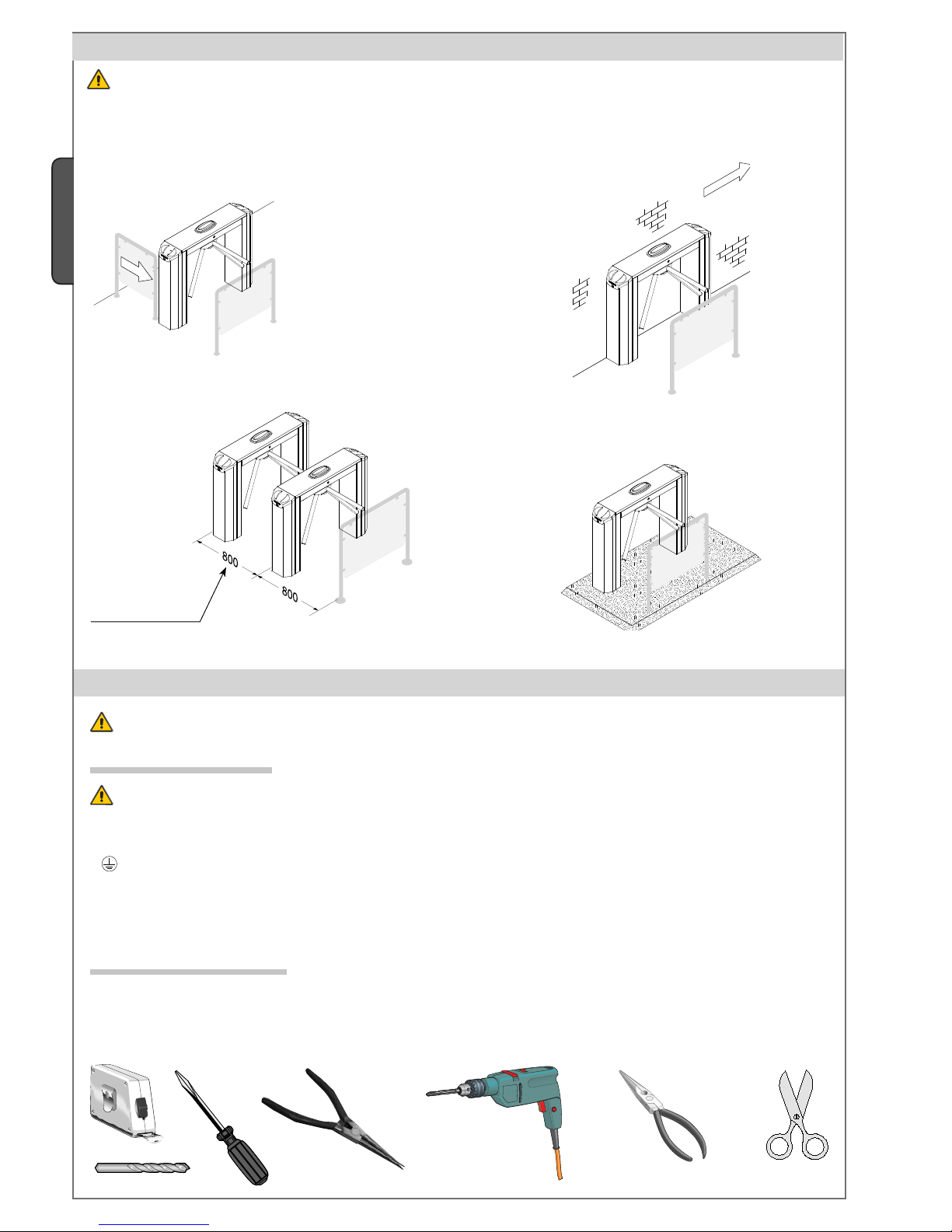
Standard installation Against the wall installation
Multiple installation
Platform installation
5 Application examples
Warning: Turnstile-controlled exits cannot serve as emergency exits. Always have an emergency exit and one also for disabled
persons.
6 Installation
Only skilled, qualified staff must perform the installation, in full compliance of the current legislation.
6.1 Preliminary checks
Before installing the automated device, please:
• Set up a proper omnipolar cut-off device, with contacts more than 3 mm apart, and power source isolation;
• Set up proper tubing and conduits for the electrical cables to go through with enough protection from any mechanical damage;
•
Check that any connections within the container (made to give continuity to the protection circuit) have additional isolation
compared to the other internal power conductors.
Make sure you have all the tools and materials needed to carry out the installation in total safety and in compliance with current
legislation. The figures shows examples of installers’ tools.
6.2 Tools and equipment
Suggested distance
between turnstiles
SWIMMING POOL
2
1
3
4
4
5
6
Pag.
5
-
Manual code
:
119G3040
119 G3 04 0 ver.
1.5
1.5 09/2010
© CAME cancelli automatici s.p.a. -
The data and information reported in this installation manual are susceptible to change at any time and without obligation on CAME cancelli automatici s.p.a. to notify users.
ENGLISH
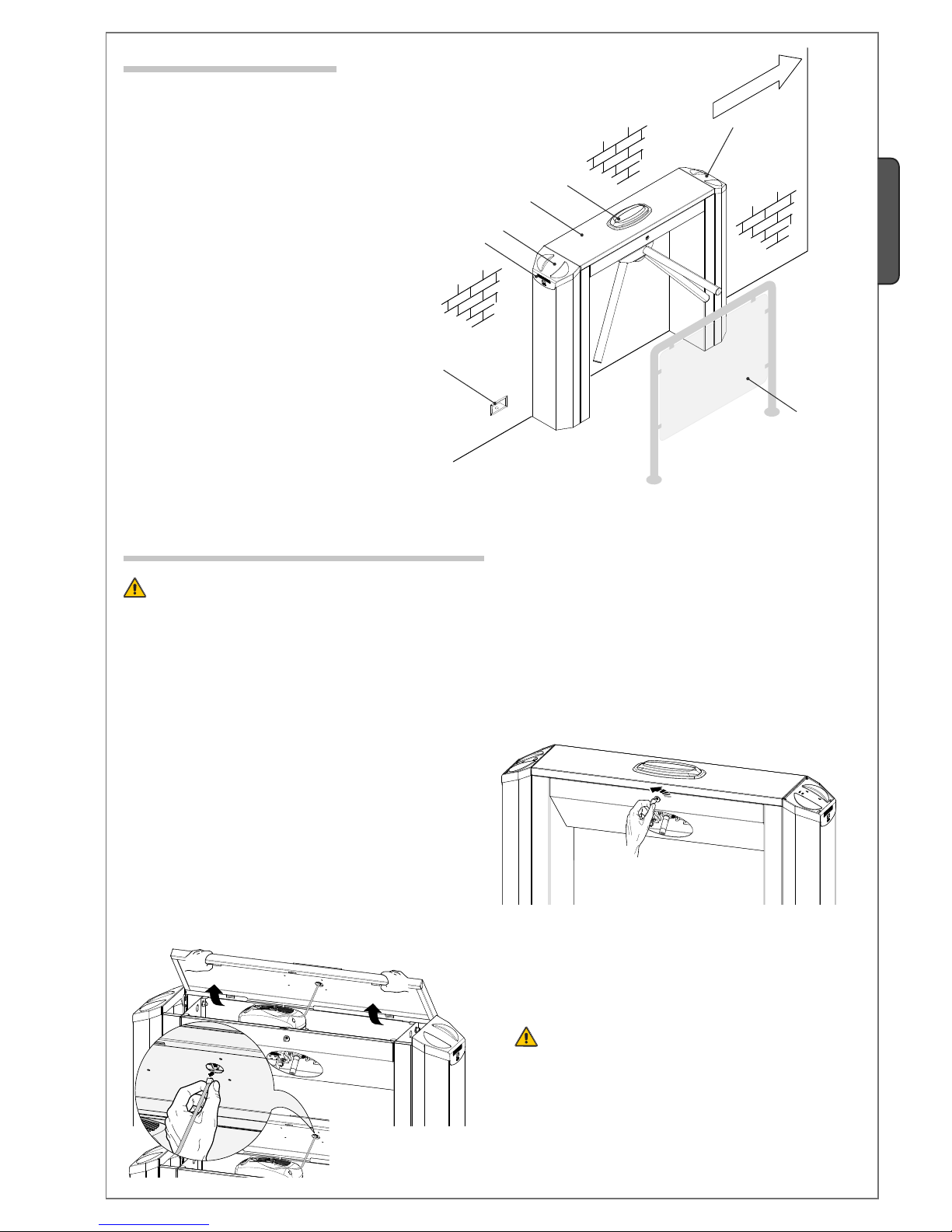
6.3 Standar installation
6.4 Setting up the turnstile
Warning: installation required two people. Use hoisting equipment to move and position the turnstile.
Do not lean on the turnstile until it is solidly anchored, to prevent it from toppling over.
1) Used the issued key to open the lock on the front part of the
turnstile.
Tripod turnstile1.
Traffi c-light with display2.
Electric wiring connector block3.
Transponder for transit access4.
Protection handrail5.
Status displays6.
2)
Raise the cover carefully so as to gently remove the
metal strip from the display (traffic light).

1
2
1
2
Pag.
6
- Manual code:
119G3040
119 G3 04 0 ver.
1.5
1.5 09/2010 © CAME cancelli automatici s.p.a. - The data and information reported in this installation manual are susceptible to change at any time and without obligation on CAME cancelli automatici s.p.a. to notify users.
ENGLISH
4) Remove the top cover.
Note: Lift the cover slightly tor easy removal.
5) Remove the two screws that fix the casing to the legs.
6) Remove the protective casings by gently lifting them. Then,
extract the casings.
6) Use the supplied M10 x 60 screws and flat washer to secure
the three arms to the tripod hub.
7) Slide the tripod onto the pin that protrudes out of the body,
secure it using the screw cap and M8 x 20 screw.
 Loading...