

Page 1
SMA2
English
SERIES R ACCESSORIES
MAGNETIC LOOP
CONTROL DEVICE
SMA2
nglis
h
SERIES R ACCESSORIES
MAGNETIC LOOP
CONTROL DEVICE
Page 2
The data and information reported in this installation manual are susceptible to change at any time and without obligation on CAME cancelli automatici s.p.a. to notify users.
Pag.
2
2 - Manual code:
119R V04
119 RV 04 ver.
0.1
0.1 03/2009 © CAME cancelli automatici s.p.a.
ENGLISH
ELECTRIC SPECIFICATIONS
Supply voltage 12/24 V ac/dc
Current draw 20 mA max
Outlet relays Max capacity: 5 A at 230 Vac - Closed contact
Magnetic loop inductance Between 20 and 1000 μH
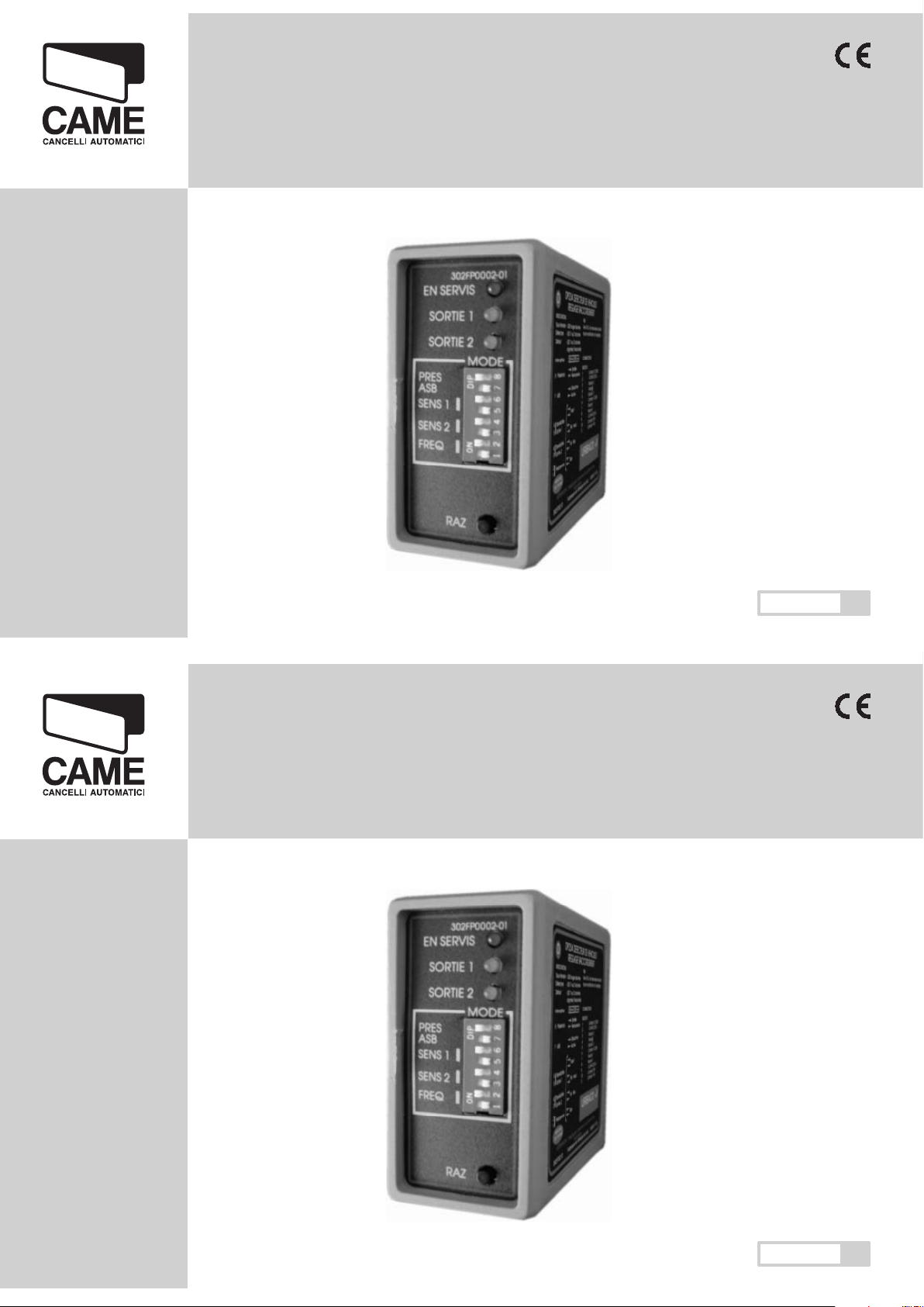
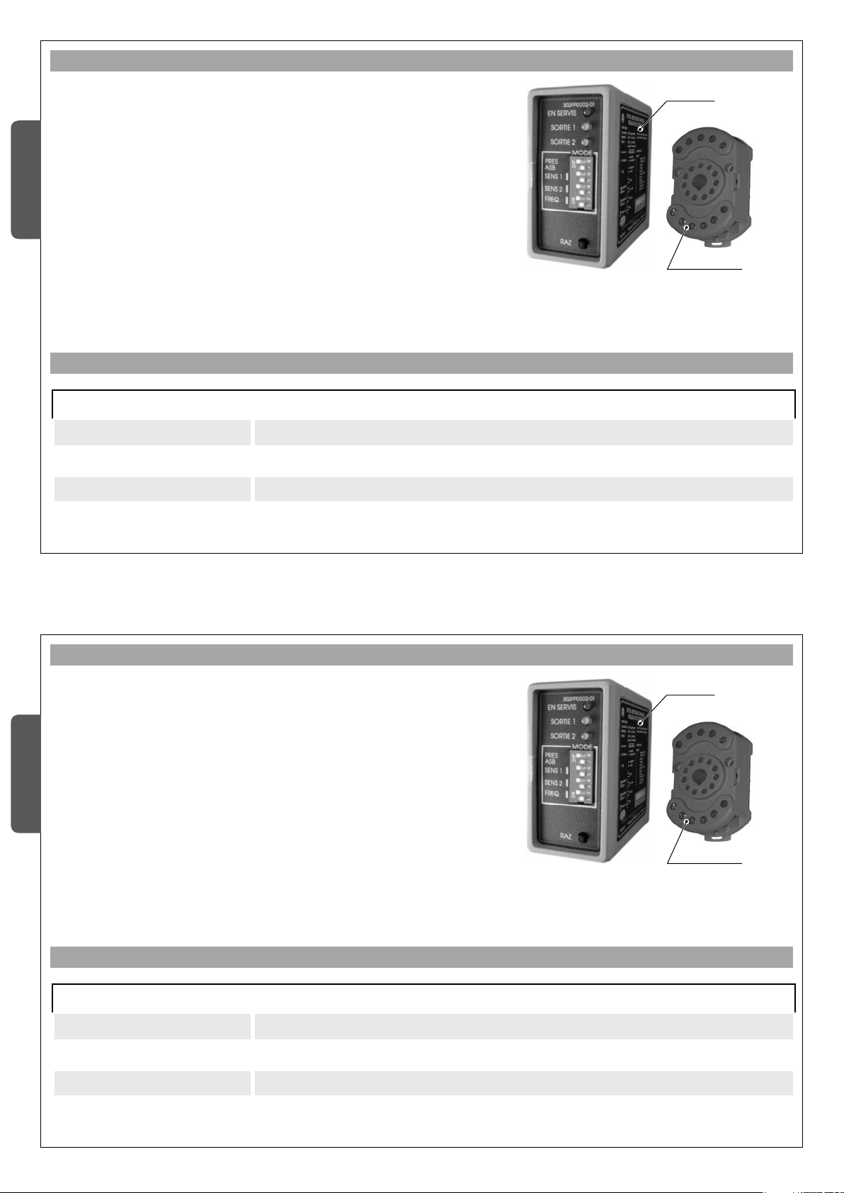
2. TECHNICAL FEATURES
The 1 channel SMA sensor is a vehicle detector using electromagnetic
loops. It is fitted with a microprocessor and has been designed for
access and traffic flow controls
The operating principle involves measuring the inductance variation in
the magnetic loop caused when a vehicle passes over it.
Inside the sensor, the measuring circuits for the two channels are
multiplied to limit oscillations and interference that could be formed
between the magnetic loops.
SMA is complete with an 11-pin support/terminal block for connection
to the loops and the 12 or 24 Vac/dc power supply.
Support
Sensor
1. DESCRIPTION
The data and information reported in this installation manual are susceptible to change at any time and without obligation on CAME cancelli automatici s.p.a. to notify users.
Pag.
2
2 - Manual code:
119R V04
119 RV 04 ver.
0.1
0.1 03/2009 © CAME cancelli automatici s.p.a.
ENGLISH
ELECTRIC SPECIFICATIONS
Supply voltage 12/24 V ac/dc
Current draw 20 mA max
Outlet relays Max capacity: 5 A at 230 Vac - Closed contact
Magnetic loop inductance Between 20 and 1000 μH
2. TECHNICAL FEATURES
The 1 channel SMA sensor is a vehicle detector using electromagnetic
loops. It is fitted with a microprocessor and has been designed for
access and traffic flow controls
The operating principle involves measuring the inductance variation in
the magnetic loop caused when a vehicle passes over it.
Inside the sensor, the measuring circuits for the two channels are
multiplied to limit oscillations and interference that could be formed
between the magnetic loops.
SMA is complete with an 11-pin support/terminal block for connection
to the loops and the 12 or 24 Vac/dc power supply.
Support
Sensor
1. DESCRIPTION
Page 3

The data and information reported in this installation manual are susceptible to change at any time and without obligation on CAME cancelli automatici s.p.a. to notify users.
Pag.
3
3 - Manual code:
119R V04
119 RV 04 ver.
0.1
0.1 03/2009 © CAME cancelli automatici s.p.a.
ENGLISH
MECHANICAL SPECIFICATIONS
Materials ABS plastic casing
Fastenings Pressure sensor on the connector; connector mounted on DIN guides or screw in place
Measurements LxHxP 42 x 78 x 103 mm (sensor + connector)
Weight 230 g
Operating temperature -40 / +70 °C
Protection rating IP30
FUNCTIONAL SPECIFICATIONS
Sensitivity
4 ranges, selected through 2 dipswitches:
- High sensitivity: 0.02%, L/L
- Medium-high sensitivity: 0.05%, L/L
- Medium-low sensitivity: 0.10% L/L
- Low sensitivity: 0.50% L/L
Working frequency
High or low frequency, selected from a dipswitch; the frequency level depends on the size of the
magnetic loop
Output impulse length 200 ms
Response time 100 ms
Visual indicators
- 1 red power on led
- 2 green leds for sensor activities
Relay outputs 2 “presence” mode outputs
Page 4
The data and information reported in this installation manual are susceptible to change at any time and without obligation on CAME cancelli automatici s.p.a. to notify users.
Pag.
4
4 - Manual code:
119R V04
119 RV 04 ver.
0.1
0.1 03/2009 © CAME cancelli automatici s.p.a.
ENGLISH
3.1. Operating principles
The inductive loop sensor detects the presence of a vehicle on the
surface marked out by a cabled loop, formed of 2 or more runs of leads
beneath the road surface.
When a vehicle goes over the loop the relative inductance measured by
the sensor is reduced.
This detection activates a relay and its contacts are used to guide the
external devices.
The magnetic loop and the loop tail must be formed of a simple isolated
lead, without any connections, in multithread copper, with a minimum
section of 1.5 mm
2
(16 AWG).
It is not advisable to make connections to the magnetic loop or to the
power pack. However, if it is unavoidable they must be welded and
isolated in a waterproof case.
This is very important to guarantee long lasting detection reliability.
3.2. Operating limits
3.2.1. Use of adjacent SMA sensors
When the magnetic loops are too close to each other, the respective
magnetic fi elds could overlap and disturb the detection or damage the
sensors.
There are various solutions to prevent this:
- use different frequencies for each magnetic loop.
- keep the two groups of loops at least 2 meters away from each
other.
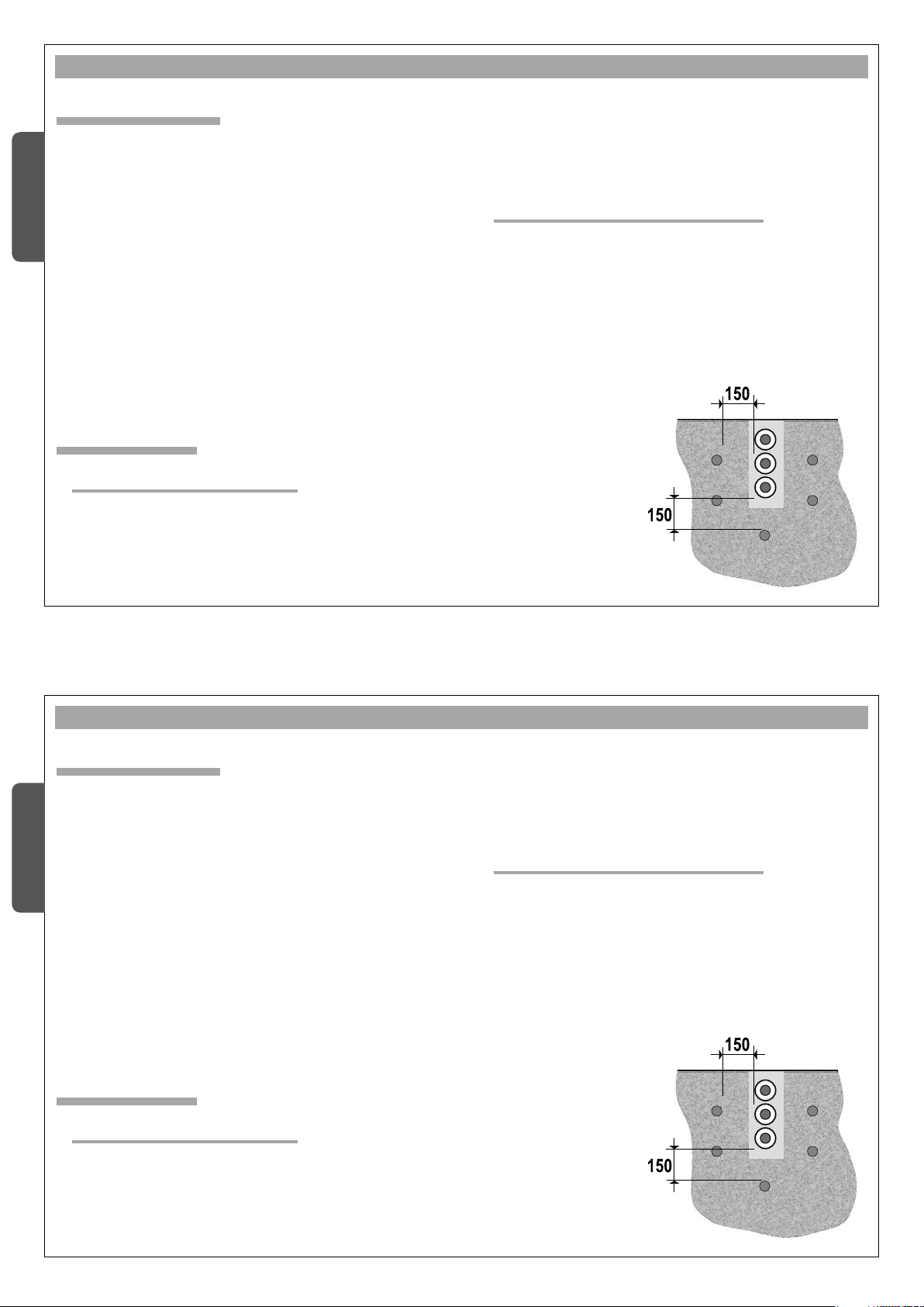
3.2.2. Interference caused by metal masses
If there is any metal under the loops, especially if they are laid in
reinforced concrete, it reduces the impedance and consequently the
sensitivity of the sensor.
To compensate this reduction, two turns can be added to the detection
loop.
Otherwise provide a minimum space of 150 mm between the magnetic
loop and the reinforcing.
If the loop tail is channelled
with other cables, ensure
that they are screened.
Clean and dry the cable duct
before laying the cable.
3. INSTALLING THE MAGNETIC LOOPS
The data and information reported in this installation manual are susceptible to change at any time and without obligation on CAME cancelli automatici s.p.a. to notify users.
Pag.
4
4 - Manual code:
119R V04
119 RV 04 ver.
0.1
0.1 03/2009 © CAME cancelli automatici s.p.a.
ENGLISH
3.1. Operating principles
The inductive loop sensor detects the presence of a vehicle on the
surface marked out by a cabled loop, formed of 2 or more runs of leads
beneath the road surface.
When a vehicle goes over the loop the relative inductance measured by
the sensor is reduced.
This detection activates a relay and its contacts are used to guide the
external devices.
The magnetic loop and the loop tail must be formed of a simple isolated
lead, without any connections, in multithread copper, with a minimum
section of 1.5 mm
2
(16 AWG).
It is not advisable to make connections to the magnetic loop or to the
power pack. However, if it is unavoidable they must be welded and
isolated in a waterproof case.
This is very important to guarantee long lasting detection reliability.
3.2. Operating limits
3.2.1. Use of adjacent SMA sensors
When the magnetic loops are too close to each other, the respective
magnetic fi elds could overlap and disturb the detection or damage the
sensors.
There are various solutions to prevent this:
- use different frequencies for each magnetic loop.
- keep the two groups of loops at least 2 meters away from each
other.
3.2.2. Interference caused by metal masses
If there is any metal under the loops, especially if they are laid in
reinforced concrete, it reduces the impedance and consequently the
sensitivity of the sensor.
To compensate this reduction, two turns can be added to the detection
loop.
Otherwise provide a minimum space of 150 mm between the magnetic
loop and the reinforcing.
If the loop tail is channelled
with other cables, ensure
that they are screened.
Clean and dry the cable duct
before laying the cable.
3. INSTALLING THE MAGNETIC LOOPS
Page 5

The data and information reported in this installation manual are susceptible to change at any time and without obligation on CAME cancelli automatici s.p.a. to notify users.
Pag.
5
5 - Manual code:
119R V04
119 RV 04 ver.
0.1
0.1 03/2009 © CAME cancelli automatici s.p.a.
ENGLISH
3.3.1. Dimensions
The magnetic loop must be rectangular with the longest side perpendicular
to the circulation direction. There must be a minimum width of 1 m.
The surface must measure at least 1 m
2
and no more than 30 m2. For a
traditional road we advise an area of 1.5 – 2 m2.
Table with indication of the number of turns per surface:
Area m2Number of turns
< 3 4
3 < 5 3
> 5 2
3.3.2. Magnetic loop tail
The tail is the connecting lead between the magnetic loop and the sensor.
It is formed of a twisted, armoured cable, or a pair in isolated multi-pole
copper, with a minimum section of 1.5 mm2 and twisted with 20 turns
per meter.
The tail must not be any longer than 25 m.
3.3. Magnetic loop geometry
Sensor
Loop tail
Magnetic loop
Page 6

The data and information reported in this installation manual are susceptible to change at any time and without obligation on CAME cancelli automatici s.p.a. to notify users.
Pag.
6
6 - Manual code:
119R V04
119 RV 04 ver.
0.1
0.1 03/2009 © CAME cancelli automatici s.p.a.
ENGLISH
4. CONNECTIONS
1 12 – 24 V ac/dc
2 12 – 24 V ac/dc
3 Loop 1
4 Loop 1
5 Loop 2
6 Loop 2
The relays in contacts 1
and 2 are prepared for
just security purposes
(photocell type).
7 Contact 2 (NC)
8 Contact 2 (COM)
9 Ground
10 Contact 1 (NC)
11 Contact 1 (COM)
Dipswitch OFF
(default)
Dipswitch ON
5. SETTING THE FUNCTIONS
5.1. Description
The leds and dipswitches for setting the functioning parameters
are in the front part of the sensors.
Use a screwdriver for the ON/OFF selection.
All the dipswitches are on OFF for default.
Page 7

The data and information reported in this installation manual are susceptible to change at any time and without obligation on CAME cancelli automatici s.p.a. to notify users.
Pag.
7
7 - Manual code:
119R V04
119 RV 04 ver.
0.1
0.1 03/2009 © CAME cancelli automatici s.p.a.
ENGLISH
5.2. Setting the parameters
5.2.1. Dipswitches 1 and 2: regulating working frequency
These dipswitches are used to select the
working frequency for the magnetic loop: this
is useful when there is more than one sensor
in a confi ned area. Generally, high frequency
is used for the magnetic loop with the highest
inductance.
Dipswitch 1 and 2 OFF: Frequency is regulated on HIGH
Dipswitch 1 OFF and 2 ON: Frequency is regulated on MEDIUM-HIGH
Dipswitch 1 ON and 2 OFF: Frequency is regulated on MEDIUM-LOW
Dipswitches 1 and 2 ON: Frequency is regulated on LOW
These dipswitches are used to regulate
the detection sensitivity. In areas with low
selection or interference, it is advisable to
lower the sensitivity.
Dipswitches 3 and 4 OFF: MAXIMUM detection sensitivity
Dipswitch 3 OFF and 4 ON: MEDIUM-MAXIMUM detection sensitivity.
Dipswitch 3 ON and 4 OFF: MEDIUM-MINIMUM detection sensitivity
Dipswitch 3 and 4 ON: MINIMUM detection sensitivity
5.2.2. Dip 3 e 4 - CH2 channel sensitivity regulation
Page 8

The data and information reported in this installation manual are susceptible to change at any time and without obligation on CAME cancelli automatici s.p.a. to notify users.
Pag.
8
8 - Manual code:
119R V04
119 RV 04 ver.
0.1
0.1 03/2009 © CAME cancelli automatici s.p.a.
ENGLISH
5.2.3. Dip 5 e 6 - CH1 channel sensitivity regulation
These dipswitches are used to regulate
the detection sensitivity. In areas with low
selection or interference, it is advisable to
lower the sensitivity.
Dipswitches 5 and 6 OFF: MAXIMUM detection sensitivity
Dipswitch 5 OFF and 6 ON: MEDIUM-MAXIMUM detection sensitivity.
Dipswitch 53 ON and 6 OFF: MEDIUM-MINIMUM detection sensitivity
Dipswitch 5 and 6 ON: MINIMUM detection sensitivity
5.2.4. Dipswitch 7 – automatically increases ASB sensitivity
This function automatically takes the sensor
sensitivity to maximum, so that irregular
shaped vehicles are recognised as well (e.g.
lorries)
Dipswitch 7 OFF – Automatic sensitivity increase DEACTIVATED
Dipswitch 7 ON – Automatic sensitivity increase ACTIVATED
5.2.5. Dipswitch 8 – Presence length
This dipswitch allows selecting either
permanent or limited detection.
It is advisable to regulate this dipswitch
on “permanent” to ensure access security.
Dipswitch 8 OFF – LIMITED PRESENCE: the sensor activates the output relay for a
preset time, after which the contact is released.
Dipswitch 8 ON – PERMANENT PRESENCE: the sensor leaves the output relay
active for as long as the vehicle is over the magnetic loop.
Page 9

The data and information reported in this installation manual are susceptible to change at any time and without obligation on CAME cancelli automatici s.p.a. to notify users.
Pag.
9
9 - Manual code:
119R V04
119 RV 04 ver.
0.1
0.1 03/2009 © CAME cancelli automatici s.p.a.
ENGLISH
5.3. Signal leds
5.3.1. Red led
• Red led on – signals that the power is turned on. .
5.3.2. Green leds
• During normal functions, each time a vehicle passes over the magnetic loop the green led lights up for
a moment to signal it has detected the vehicle
• Each time the device is turned off (before activating or after the power is turned back on) during
automatic setting, the green led fl ashes for a few moments until the procedure has been completed.
• If the green led fl ashes twice for one second at regular intervals, it shows there is a fault in the
detection loop.
• If the green led remains on and then goes off briefl y when a vehicle passes (opposite to the normal
function), it shows that there has been a fault or malfunction that has been solved independently: in this
case reset the system
5.4. Reset button
SMA automatically starts setting the magnetic loops when the device is turned on.
A new setting could be required manually, for example if the sensor parameters have been reset
(changing the dipswitches): when the reset button is pressed the setting is started up.
Page 10

Spiraal 2
Spiraal 1
The data and information reported in this installation manual are susceptible to change at any time and without obligation on CAME cancelli automatici s.p.a. to notify users.
Pag.
10
10 - Manual code:
119R V04
119 RV 04 ver.
0.1
0.1 03/2009 © CAME cancelli automatici s.p.a.
ENGLISH
5.5. Driving direction recognition function
5.5.1. “Direction” mode description
When the vehicle magnetic detector is connected to an access control
device, a function could be required that recognises the driving direction
of the vehicle (in/out) to allow managing a vehicle counter, for example.
5.5.2. How the “Direction” mode works
To detect the direction of the vehicle 2 magnetic loops must be installed
in series and close to each other; depending on the direction of the
vehicle, SMA2 will activate one or other of the output relays.
ATTENTION: for the “Direction” mode to work correctly, the two
magnetic loops must be close enough so that the vehicle is detected by
them both at the same time.
The vehicle must not have left the fi rst loop before it meets the second.
Driving direction Relay activated
From loop 1 to loop 2 Relay 1
From loop 2 to loop 1 Relay 2
Page 11

The data and information reported in this installation manual are susceptible to change at any time and without obligation on CAME cancelli automatici s.p.a. to notify users.
Pag.
11
11 - Manual code:
119R V04
119 RV 04 ver.
0.1
0.1 03/2009 © CAME cancelli automatici s.p.a.
ENGLISH
5.5.3. How to activate the “Direction” mode
To activate this function, reach the sensor board (see fi gure
A) to change the confi guration of 3 jumpers and alter the
status of the NC to NO contacts, as shown in fi gures B and
C.
fi g.C
fi g. A
Using a fl at screwdriver, carefully force the
point as shown and carefully remove the board,
pressing on the front and pulling at the bottom
(the board slides along a track in the container).
Unsolder and then
re-solder the wires
From J6 to J5
and from J9 to J8
Jumper A = left
engaged
Jumpers B and
C = bridges
engaged
fi g. B
Jumper
Bridge
A
B
C
Page 12

FRANCE -
CAME France S.a .
CAME France S.a.
7, Rue Des Haras - Z.i. Des Hautes Patures
92737
Nanterre Cedex
Nanterre Cedex - - (+33) 1 46 13 05 05 - (+33) 1 46 13 05 00
CAME GmbH Nord
CAME GmbH Nord - DEUTSCHLAND
Akazienstraße, 9
16356
Seefeld
Seefeld - (+49) 33 3988390 _ (+49) 33 39883985
FRANCE -
CAME Au to ma ti sm es S.a.
CAME Automatismes S.a.
3, Rue Odette Jasse
13015
Marseille -
Marseille - (+33) 4 95 06 33 70 - (+33) 4 91 60 69 05
CAME GmbH Süd
CAME GmbH Süd - DEUTSCHLAND
Kornwestheimer Straße 37
70825
Kor ntal-
Korntal-Münchingen
- (+49) 71 5037830 _ (+49) 71 50378383
SPAIN -
CAME Au to ma ti sm os S.a.
CAME Automatismos S.a.
C/juan De Mariana, N. 17-local
28045
Madrid -
Madrid - (+34) 91 52 85 009 - (+34) 91 46 85 442
CAME Am er ic as Au to mation Llc
CAME Americas Automation Llc - U.S.A
1560 Sawgrass Corporate Pkwy, 4th Floor
Sunrise
Sunrise, FL 33323 - (+1) 305 433 3307 _ (+1) 305 396 3331
SPAIN -
CAME Au to ma ti sm os C at al un ya S.a .
CAME Automatismos Catalunya S.a.
P.i. Moli Dels Frares N. 23 C/a
08620
Sant V ic en c De l Ho rt s
Sant Vicenc Del Horts - - (+34) 93 65 67 694 - (+34) 93 67 24 505
CAME Middle East F zc o -
CAME Middle East Fzco - U.A.E.
Po Box 17131 Warehouse N. Be02 - South Zone, Jebel Ali Free Zone
Dubai
Dubai - (+971) 4 8860046 _ (+971) 4 8860048
PORTUGAL -
Paf - CAME
Paf - CAME
Estrada Nacional 249-4 Ao Km 4,35 - Cabra Figa - Trajouce
2635-047
Rio De Mouro -
Rio De Mouro - (+351) 219 257 471 - (+35) 219 257 485
CAME Polska Sp.Zo.o -
CAME Polska Sp.Zo.o - POLAND
Ul. Ordona 1
01-237
War sz aw a
Warszawa - (+48) 22 8365076 _ (+48) 22 8363296
UNITED KINGDOM -
CAME United King do m Lt d.
CAME United Kingdom Ltd.
Unit 3 Orchard Business Park - Town Street, Sandiacre
Nottingham
Nottingham Ng10 5du - (+44) 115 9210430 - (+44) 115 9210431
S.c. C AM E Ro mania S. r.l. -
S.c. CAME Romania S.r.l. - ROMANIA
B-dul Mihai Eminescu, Nr. 2, Bloc R2 - Scara A, Parter, Ap. 3
Buftea, Judet Ilfov
Bucarest
Bucarest
- (+40) 21 3007344 _ (+40) 21 3007344
BELGIUM -
CAME Belgium Spr l
CAME Belgium Sprl
Zoning Ouest 7
7860
Lessines -
Lessines - (+32) 68 333014 - (+32) 68 338019
CAME Russia
CAME Russia - RUSSIA
Leningradskij Prospekt, Dom 80 - Pod’ezd 3, offi ce 608
125190,
Moskva
Moskva - (+7) 495 937 33 07 _ (+7) 495 937 33 08
ITALIA -
CAME Cancelli A ut om at ic i S.p.a.
CAME Cancelli Automatici S.p.a.
Via Martiri Della Libertà, 15
31030
Dosson Di Casie r
Dosson Di Casier (TV) - (+39) 0422 4940 _ (+39) 0422 4941
Informazioni Commerciali 800 848095 -
www.came.it
www.came.it
CAME Nord s.r.l.
CAME Nord s.r.l. - ITALIA
Piazza Castello, 16
20093
Cologno Monzese
Cologno Monzese (MI)
- (+39) 02 26708293 _ (+39) 02 25490288
ITALIA -
CAME Ser vi ce I ta li a S.r.l.
CAME Service Italia S.r.l.
Via Della Pace, 28
31030
Dosson di Casie r
Dosson di Casier (TV)
- (+39) 0422 383532 _ (+39) 0422 490044
Assistenza Tecnica 800 29583 0
Assistenza Tecnica 800 295830
CAME Sud s.r.l .
CAME Sud s.r.l. - ITALIA
Via F. Imparato, 198 - Cm2 Lotto A/7
80146
Napoli -
Napoli - (+39) 081 7524455 _ (+39) 081 7529109
En glish
English - Manual code:
119RV 0 4
119RV04 ver.
0.1
0.1 03/2009 © C AME cancelli automatici s.p.a.
The data and information reported in this installation manual are susceptible to change at any time and
without obligation on CAME cancelli automatici s.p.a. to notify users.
The declaration de conformit y and other technical documentation are available on our website ww w.came.it
BUY-TO-SELL PRODUCT
FRANCE -
CAME France S.a .
CAME France S.a.
7, Rue Des Haras - Z.i. Des Hautes Patures
92737
Nanterre Cedex
Nanterre Cedex - - (+33) 1 46 13 05 05 - (+33) 1 46 13 05 00
CAME GmbH Nord
CAME GmbH Nord - DEUTSCHLAND
Akazienstraße, 9
16356
Seefeld
Seefeld - (+49) 33 3988390 _ (+49) 33 39883985
FRANCE -
CAME Au to ma ti sm es S.a.
CAME Automatismes S.a.
3, Rue Odette Jasse
13015
Marseille -
Marseille - (+33) 4 95 06 33 70 - (+33) 4 91 60 69 05
CAME GmbH Süd
CAME GmbH Süd - DEUTSCHLAND
Kornwestheimer Straße 37
70825
Kor ntal-
Korntal-Münchingen
- (+49) 71 5037830 _ (+49) 71 50378383
SPAIN -
CAME Au to ma ti sm os S.a.
CAME Automatismos S.a.
C/juan De Mariana, N. 17-local
28045
Madrid -
Madrid - (+34) 91 52 85 009 - (+34) 91 46 85 442
CAME Am er ic as Au to mation Llc
CAME Americas Automation Llc - U.S.A
1560 Sawgrass Corporate Pkwy, 4th Floor
Sunrise
Sunrise, FL 33323 - (+1) 305 433 3307 _ (+1) 305 396 3331
SPAIN -
CAME Au to ma ti sm os C at al un ya S.a .
CAME Automatismos Catalunya S.a.
P.i. Moli Dels Frares N. 23 C/a
08620
Sant V ic en c De l Ho rt s
Sant Vicenc Del Horts - - (+34) 93 65 67 694 - (+34) 93 67 24 505
CAME Middle East F zc o -
CAME Middle East Fzco - U.A.E.
Po Box 17131 Warehouse N. Be02 - South Zone, Jebel Ali Free Zone
Dubai
Dubai - (+971) 4 8860046 _ (+971) 4 8860048
PORTUGAL -
Paf - CAME
Paf - CAME
Estrada Nacional 249-4 Ao Km 4,35 - Cabra Figa - Trajouce
2635-047
Rio De Mouro -
Rio De Mouro - (+351) 219 257 471 - (+35) 219 257 485
CAME Polska Sp.Zo.o -
CAME Polska Sp.Zo.o - POLAND
Ul. Ordona 1
01-237
War sz aw a
Warszawa - (+48) 22 8365076 _ (+48) 22 8363296
UNITED KINGDOM -
CAME United King do m Lt d.
CAME United Kingdom Ltd.
Unit 3 Orchard Business Park - Town Street, Sandiacre
Nottingham
Nottingham Ng10 5du - (+44) 115 9210430 - (+44) 115 9210431
S.c. C AM E Ro mania S. r.l. -
S.c. CAME Romania S.r.l. - ROMANIA
B-dul Mihai Eminescu, Nr. 2, Bloc R2 - Scara A, Parter, Ap. 3
Buftea, Judet Ilfov
Bucarest
Bucarest
- (+40) 21 3007344 _ (+40) 21 3007344
BELGIUM -
CAME Belgium Spr l
CAME Belgium Sprl
Zoning Ouest 7
7860
Lessines -
Lessines - (+32) 68 333014 - (+32) 68 338019
CAME Russia
CAME Russia - RUSSIA
Leningradskij Prospekt, Dom 80 - Pod’ezd 3, offi ce 608
125190,
Moskva
Moskva - (+7) 495 937 33 07 _ (+7) 495 937 33 08
ITALIA -
CAME Cancelli A ut om at ic i S.p.a.
CAME Cancelli Automatici S.p.a.
Via Martiri Della Libertà, 15
31030
Dosson Di Casie r
Dosson Di Casier (TV) - (+39) 0422 4940 _ (+39) 0422 4941
Informazioni Commerciali 800 848095 -
www.came.it
www.came.it
CAME Nord s.r.l.
CAME Nord s.r.l. - ITALIA
Piazza Castello, 16
20093
Cologno Monzese
Cologno Monzese (MI)
- (+39) 02 26708293 _ (+39) 02 25490288
ITALIA -
CAME Ser vi ce I ta li a S.r.l.
CAME Service Italia S.r.l.
Via Della Pace, 28
31030
Dosson di Casie r
Dosson di Casier (TV)
- (+39) 0422 383532 _ (+39) 0422 490044
Assistenza Tecnica 800 29583 0
Assistenza Tecnica 800 295830
CAME Sud s.r.l .
CAME Sud s.r.l. - ITALIA
Via F. Imparato, 198 - Cm2 Lotto A/7
80146
Napoli -
Napoli - (+39) 081 7524455 _ (+39) 081 7529109
En glish
English - Manual code:
119RV 0 4
119RV04 ver.
0.1
0.1 03/2009 © C AME cancelli automatici s.p.a.
The data and information reported in this installation manual are susceptible to change at any time and
without obligation on CAME cancelli automatici s.p.a. to notify users.
The declaration de conformit y and other technical documentation are available on our website ww w.came.it
BUY-TO-SELL PRODUCT
 Loading...