

Page 1

Brushless automatic barrier
GARD PT series
FA01119-EN
GPT40AGS
INSTALLATION MANUAL
English
Page 2
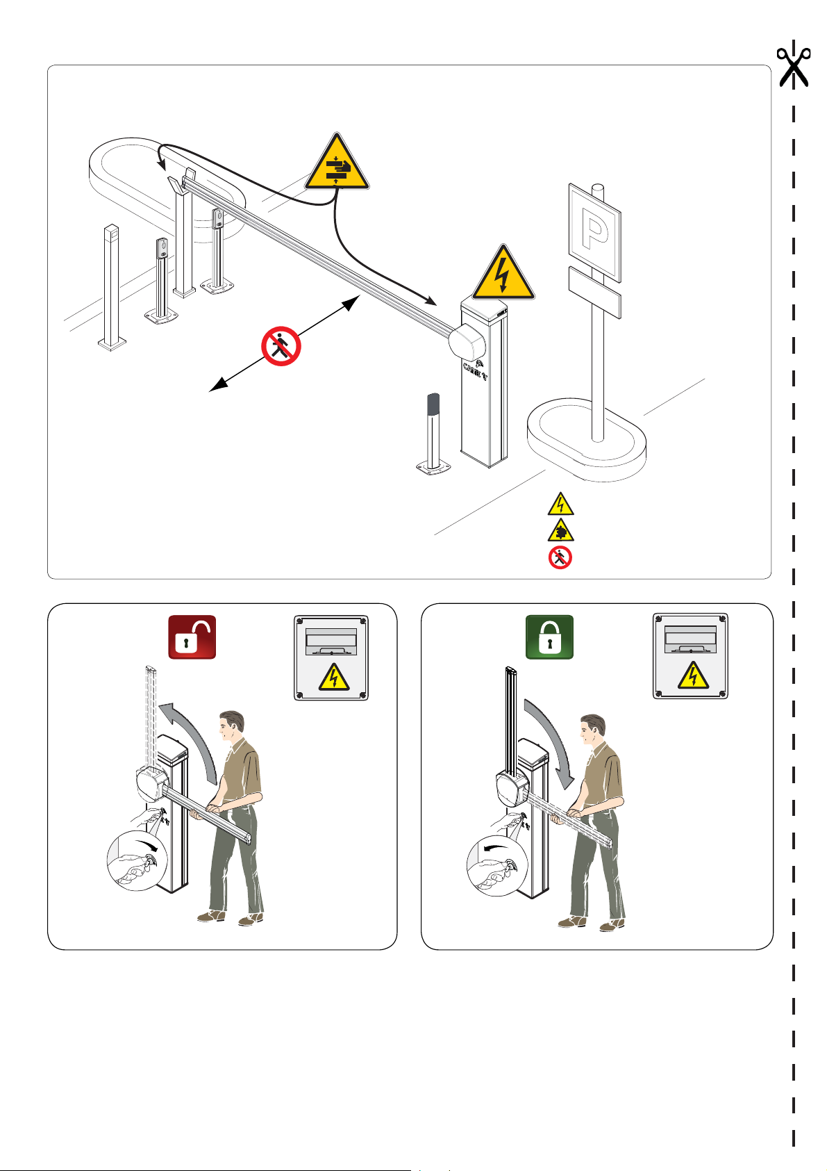
DANGER OF HIGH VOLTAGE
DANGER OF HAND ENTRAPMENT
DO NOT ENTER
OFF
CAUTION: Once you have released the barrier by using the corresponding key, we highly recommend to lock the barrier into place again once it
has opened, by turning the same key as shown in figure B.
Not locking the barrier back into place may result in it uncontrollably falling unless it is perfectly horizontal.
OFF
Page 3

GENERAL PRECAUTIONS FOR INSTALLERS
CAUTION! Important safety instructions.
Follow all of these instructions. Improper installation can cause serious bodily harm.
Before continuing, also read the general precautions for users.
Before doing any cleaning or maintaining or parts-replacing, cut o the mains power supply.
If there is a power outage and the barrier is not fi tted with an electric lock, strong gusts of wind could cause the barrier to descend
by itself in a controlled manner.
This product must only be used for its specifi cally intended purpose. Any other use is dangerous. Came S.P.A. is not liable for any
damage caused by improper, wrongful and unreasonable use. • This manual's product is defi ned by machinery directive 2006/42/
CE as "partly-completed machinery". Partly-completed machinery is a set that almost constitutes a machine, but which, alone,
cannot ensure a clearly defi ned application. Partly-completed machinery is only destined to be incorporated or assembled to
other machinery or other partly-completed machinery or apparatuses to build machinery that is regulated by Directive 2006/42/
CE. The fi nal installation must comply with Machinery Direction 2006/42/CE and current European reference standards. • Given
these considerations, all procedures stated in this manual must be exclusively performed by expert, qualifi ed sta . • Laying the
cables, installation and testing must follow state-of-the-art procedures as dictated by regulations • Make sure that the opening
automatic barrier does not constitute a hazard. • Do not install the operator onto surfaces that could yield and bend. If necessary,
add suitable reinforcements to the anchoring points • Make sure the temperature range shown on the product literature is
suitable to the climate where it will be installed. • Do not install on slopes, that is, on any surfaces that are not perfectly level. •
Check that no lawn watering devices spray the operator with water from the bottom up. •Check that there are no obstruction or
impediments near the cabinet. • During the set up and installing stages the barrier could be unstable and tip over. So, be careful
and do not lean on it until it is fully fastened.• Suitably section o and demarcate the entire installation site to prevent unauthorized
persons from entering the area, especially minors and children. • Be careful when manually moving weights of over 20 kg per
person; if manually moving such weights, use suitable and safe hoisting equipment . • Please use suitable protections to prevent
any mechanical hazards when people are moving around the machinery. • Any residual risks must be notifi ed by proper, clearly
visible pictograms, which must be explained to end users. • Fit, in plain sight, the machine's ID plate when the installation is
complete. • Install all fi xed commands at least 1.5 m from the ground where they will be clearly visible, within view of the part they
command but clear of any moving parts. Any maintained action commands must not be reachable by unauthorized persons. •
The manufacturer declines any liability for using non-original products, in which case the warranty will cease to be e ective. • For
booms longer than 2.5 m you must fi t a reinforcement on the boom itself, as shown later in this manual. • A x a permanent tag,
that describes how to use the manual release mechanism, close to the mechanism. • Before turning over to the fi nal user, check
that the system complies with the harmonized standards and the essential requisites of Machinery Directive 2006/42/CE. Make
sure that the operator has been properly adjusted and that the safety and protection devices, and the manual release, are working
properly. • Using original CAME control and safety devices and accessories ensures easy installation and system maintenance.• If
the power-supply cable is damaged, it must be replaced by the manufacturer or by the licensed technical-assistance center or by
duly trained, skilled sta , to prevent any risks. • During all phases of the installation make sure you have cut o the mains power
source. • The electrical cables must run through suitable tubes, conduits and cable glands to ensure they are protected against
mechanical damage, They must not touch any parts that may overheat during operation, such as the motor or the transformer. •
Set up a suitable dual pole cut o device along the power supply that is compliant with the installation rules. It should completely
cut o the power supply according to category III surcharge conditions. • When the passage width clearance is greater than 3
m, you must use a fi xed rest for the boom to support it. • Keep the section of this manual inside the technical folder along with
the manuals of all the other devices used for your automation system. Remember to hand over to the end users all the operating
manuals of the products that make up the fi nal machinery.
Figure shows a standard installation: used for motor vehicels. The main hazard points for people are shown in the diagram.
p. 3 - Manual FA 01119 - E N - 10/2018 - © CAME S.p.A. - The contents of this manual may be changed, at any time, and without notice. - This is a translation of the original instructions
p. 3 - Manual FA 01119 - E N - 10/2018 - © CAME S.p.A. - The contents of this manual may be changed, at any time, and without notice. - Original instructions
Page 4
KEY
This symbol shows which parts to read carefully.
This symbol shows which parts describe safety issues
⚠
This symbol shows which parts to tell users about.
☞
Unless otherwise stated, these operations apply to all models.
The measurements, unless otherwise stated, are in millimeters.
DESCRIPTION
GPT40AGS- Automatic barrier with reversible gearmotor and brushless motor; painted aluminum cabinet ready to fit accessories.
Intended use
The automatic barrier is designed for private and public parking facilities.
Do not install of use this device in any way, except as specified in this manual.
Limits to use
Model GPT40AGS
Maximum clearance width of the passage (m) 3.8
Technical data
Type GPT40AGS
Protection rating (IP) 44
Power supply (V - 50/60 Hz) 230 V
Input voltage motor (V) 36 DC
Stand-by consumption (W) 12
Power (W ) 350
Torque (Nm)
80 (with no springs)
140 (with springs)
Opening time at 90° (s) 1.2 to 4
Cycles/h See table on page 14
Operating temperature (°C) -20 to +55
Reduction ratio (i) 1/56
Apparatus class I
Weight (Kg) 38.6
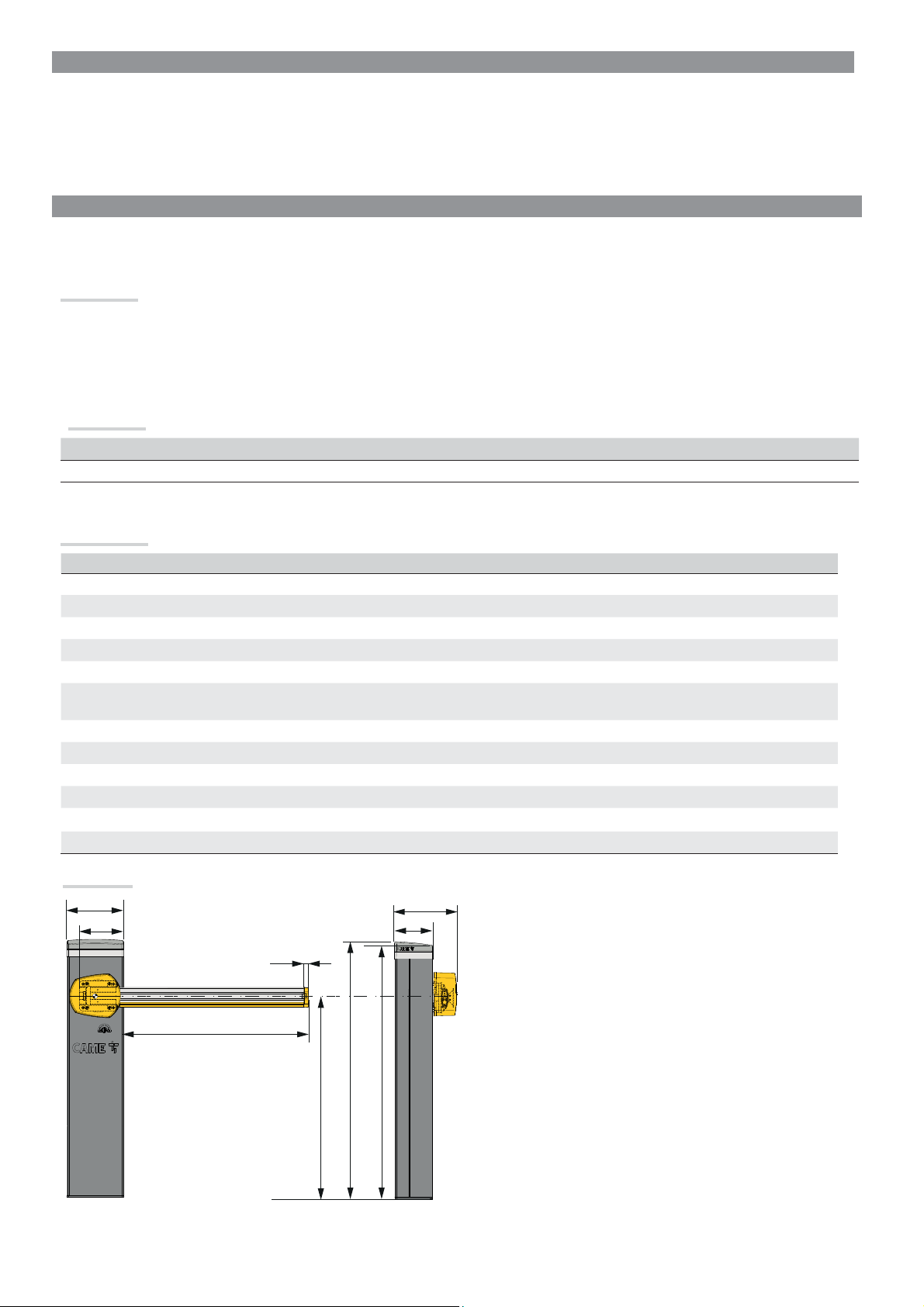
Dimensions
250
206.5
20
276
170
3800 max
884
1133
1117
p. 4 - Manual FA 01119 - E N - 10/2018 - © CAME S.p.A. - The contents of this manual may be changed, at any time, and without notice. - This is a translation of the original instructions
p. 4 - Manual FA 01119 - E N - 10/2018 - © CAME S.p.A. - The contents of this manual may be changed, at any time, and without notice. - Original instructions
Page 5
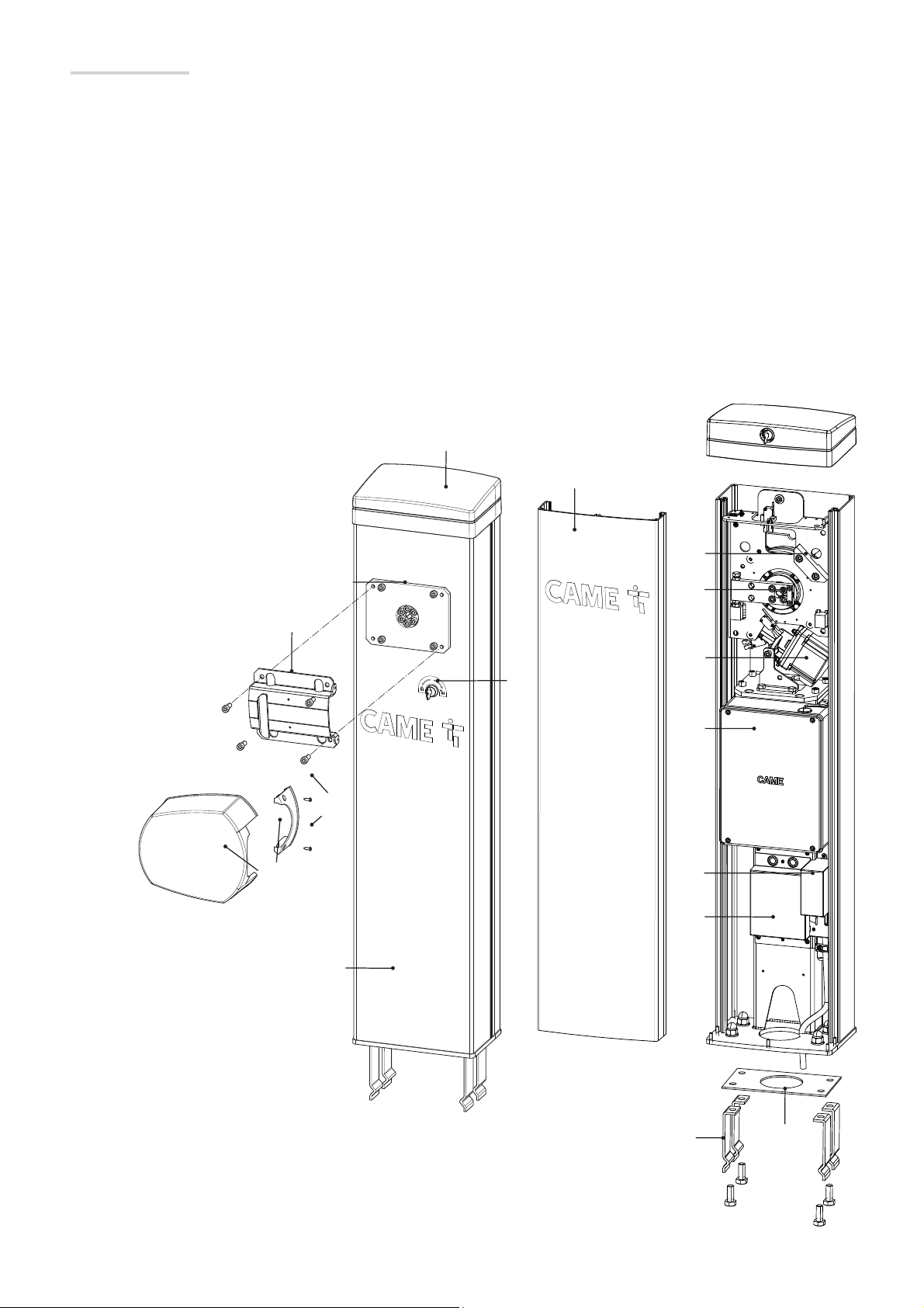
Description of parts
❶ Motor-shaft plate
❷ Boom-attachment cover
❸ Protective casing shear proof
❹ Fastening screws protective cover
❺ Control panel
❻ Boom setting mechanical stop
❼ Gear motor with encoder
❽ Lever arm
❾ Cover
❿ Cabinet
⓫ Inspection hatch
⓬ Anchoring plate
⓭ Anchoring bracket
⓮ Filter cover
⓯ Transformer cover
⓰ Lock for manual release
❾
⓫
❸
❷
❶
❹
❿
❻
❽
❼
⓰
❺
⓮
⓯
⓭ ⓬
p. 5 - Manual FA 01119 - E N - 10/2018 - © CAME S.p.A. - The contents of this manual may be changed, at any time, and without notice. - This is a translation of the original instructions
p. 5 - Manual FA 01119 - E N - 10/2018 - © CAME S.p.A. - The contents of this manual may be changed, at any time, and without notice. - Original instructions
Page 6
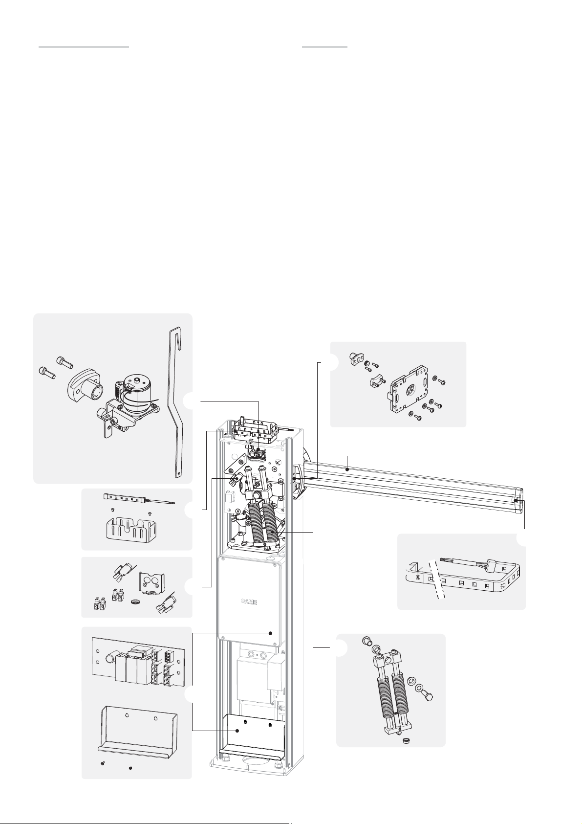
Completion accessories
Accessories
❶ 803XA-0050
Boom 90x35 (L= 4050)
803XA-0051
Boom 90x35 (L = 3050)
❷ 803XA-0070
GARD PT spring unit
❸ 803XA-0010
GARD PT luminous gearwheel
❹ 803XA-0030
Electric lock assembly
❺ 803XA-0080
Auxiliary contacts for checking the position of the boom
❻ 806SA-0080
GARD PT battery charging kit
❼ 803XA-0020
LED strip (Boom L = 4050)
803XA-0150
LED strip (Boom L = 3050)
803XA-0160
LED strip (Boom L = 2000)
❽ 803XA-0040
Detachable boom-supporting assembly
4
❹
3
❸
5
❺
8
❽
1
❶
1
7
❼
6
❻
2
❷
p. 6 - Manual FA 01119 - E N - 10/2018 - © CAME S.p.A. - The contents of this manual may be changed, at any time, and without notice. - This is a translation of the original instructions
p. 6 - Manual FA 01119 - E N - 10/2018 - © CAME S.p.A. - The contents of this manual may be changed, at any time, and without notice. - Original instructions
Page 7
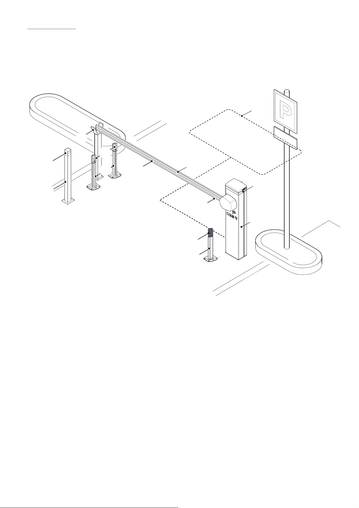
Standard installation
❶Barrier
❷Reflective strips
❸LED strip
❹Anti-collision profile
❺Luminous gearwheel
❻Photocell
❼Small photocell post
❽
❻
❽Fixed rest
❾Coil
❿Control device post
⓫Control device (keypad selector, transponder sensor)
9 9
❾
⓫
❿
❼
❷
❸
❺
❹
❶
❻
❼
p. 7 - Manual FA 01119 - E N - 10/2018 - © CAME S.p.A. - The contents of this manual may be changed, at any time, and without notice. - This is a translation of the original instructions
p. 7 - Manual FA 01119 - E N - 10/2018 - © CAME S.p.A. - The contents of this manual may be changed, at any time, and without notice. - Original instructions
Page 8
Cable types and minimum thicknesses
Connection
Power-supply at 230 V AC
Cable length
1 < 15 m
3G x 1.5 mm
2
Photocell transmitters 2 x 0.5 mm
Photocell receivers 4 x 0.5 mm
Command and safety device 2 x 0.5 mm
Cable length
15 < 30 m
3G x 2.5 mm
2
2
2
2
Antenna max 10 m
Paired or CRP (Came Remote Protocol) connection max 1,000 m (*)
Metal mass detector (see product literature)
(*) 1000 m with 001UR042; 1000 m with 001RGSM001, 001RGSM001S, 001RSLV001 (Cloud connectivity devices). With a 230V AC power
supply and using it outdoors, use H05RN-F type cables compliant with 60245 IEC 57 (IEC); whereas indoors, use H05VV-F-type cables that are
60227 IEC 53 (IEC) compliant.
To connect to the CRP, use UTP CAT5-type cables up to 1,000 m in length.
Use RG58 cable up to 10 m long to connect the antenna.
If cable lengths di er from those specifi ed in the table, establish the cable sections depending on the actual power draw of the connected
devices and according to the provisions of regulation CEI EN 60204-1.
For multiple, sequential loads along the same line, the dimensions on the table need to be recalculated according to the actual power draw and
distances. For connecting products that are not contemplated in this manual, see the literature accompanying said products
INSTALLING
The following illustrations are mere examples. Consider that the space available where to fit the barrier and accessories will vary depending on
⚠
the area where it is installed. It is up to the installer to find the most suitable solution.
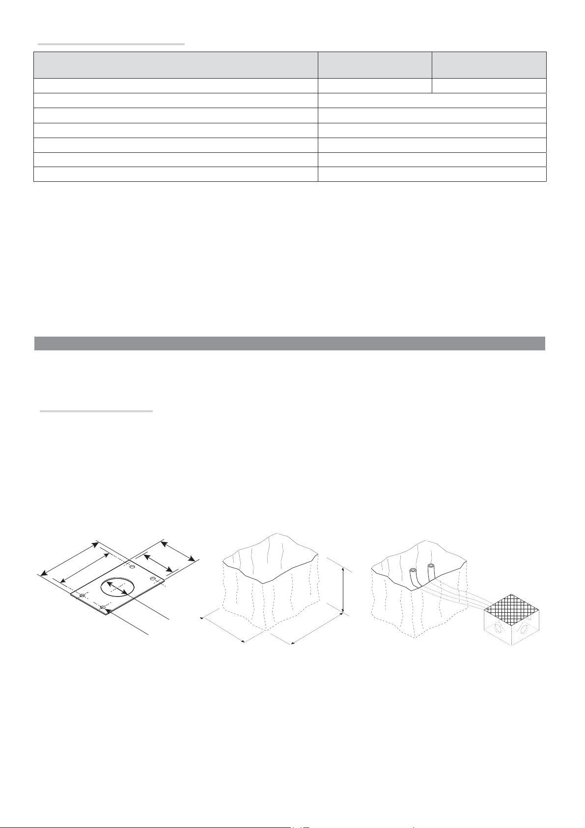
Preparing the fastening plate.
If the flooring does not allow for a sturdy fastening of the entry unit, you will have to set up a cement slab.
⚠
Dig a hole for the foundation frame.
Set up the corrugated tubes needed for the wiring coming out of the junction pit.
The number of tubes depends on the type of system and the accessories you are going to fit.
160
240
200
Ø 12,5
70
Ø 80
340
400
500
p. 8 - Manual FA 01119 - E N - 10/2018 - © CAME S.p.A. - The contents of this manual may be changed, at any time, and without notice. - This is a translation of the original instructions
p. 8 - Manual FA 01119 - E N - 10/2018 - © CAME S.p.A. - The contents of this manual may be changed, at any time, and without notice. - Original instructions
Page 9
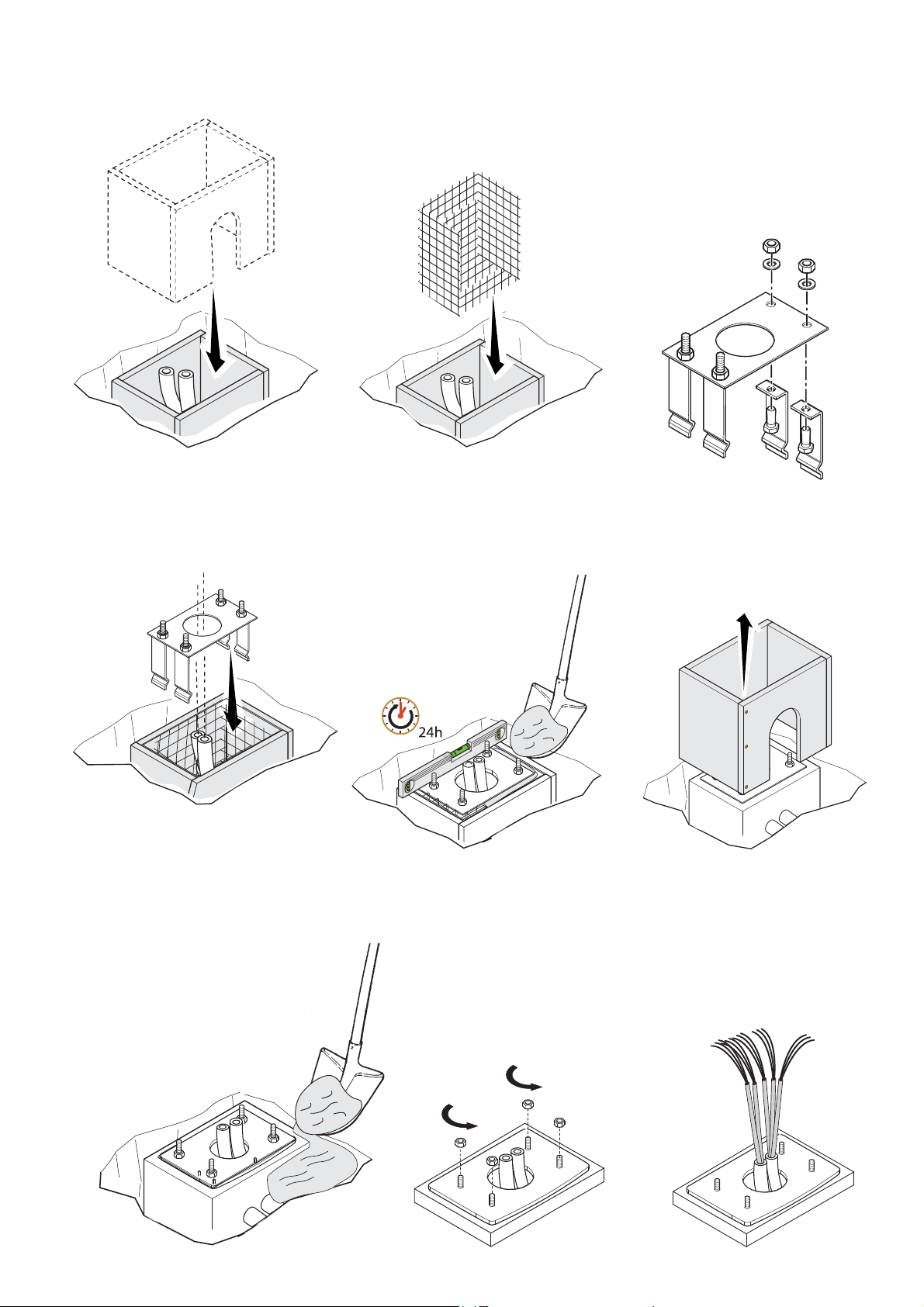
Set up a foundation frame that is larger than the anchoring plate and sink it into the dug hole.
Fit an iron cage into the foundation frame to reinforce the concrete.
Assemble the four anchoring braces to the anchoring plate.
Place the plate over the iron cage.
Fill the foundation frame with concrete. The base must be perfectly level with the bolts which are entirely above surface.
Wait at least 24 hrs for the concrete to solidify.
Remove the foundation frame.
Fill the hole with earth around the concrete block.
Remove the nut and washer from the bolts
Fit the electrical cables into the tubes until they come out at the necessary lenght
p. 9 - Manual FA 01119 - E N - 10/2018 - © CAME S.p.A. - The contents of this manual may be changed, at any time, and without notice. - This is a translation of the original instructions
p. 9 - Manual FA 01119 - E N - 10/2018 - © CAME S.p.A. - The contents of this manual may be changed, at any time, and without notice. - Original instructions
Page 10

Preparing the barrier
- Fit the key into the lock and turn it counter clockwise ❶.
- Raise the cover and disconnect the two earthing cables ❷.
- Removethe inspection hatch ❸ ❹.
❶
The barrier is set up for installing on the left.
⚠
When installing on the right, invert the boom's opening direction,
as follows:
❶ Check that the lever arm is in vertical position, as shown in
the drawing.
❷ Remove the mechanical stop by using an Allen wrench.
❸ Fasten the mechanical stop as shown in the drawing ❷.
❹ Change the parameter of function F54 (invert direction of
travel).
n
❶
❷
❸
❹
Left
Right
❷
o
p
❸
ESC < > ENTER
p. 10 - Manual FA01119-EN- 10/2018 - © CAME S.p.A. - The contents of this manual may be changed, at any time, and without notice. - This is a translation of the original instructions
p. 10 - Manual FA01119-EN- 10/2018 - © CAME S.p.A. - The contents of this manual may be changed, at any time, and without notice. - Original instructions
Page 11

Installing the barrier
The cabinet should be installed with the inspection hatch on the most accessible side to make any adjusting easier.
Place the cabinet onto the anchoring plate and fasten it using nuts and washers.
Fasten the fastening flange to the motor shaft plate by using a supplied UNI5931 M8X20 screw and .
Insert the 803XA-0110 supplied as standard..
⚠
UNI5931 M8x20
p. 11 - Manual FA 01119 -EN - 10/2018 - © CAME S.p.A. - The contents of this manual may be changed, at any time, and without notice. - This is a translation of the original instructions
p. 11 - Manual FA 01119 -EN - 10/2018 - © CAME S.p.A. - The contents of this manual may be changed, at any time, and without notice. - Original instructions
Page 12

Fit the boom into the fastening flange and fasten it using the screws ❶❷.
❷
❶
Cut the groove covering frame to the right length and fit them into the boom grooves on either side ❸❹.
Fit the rubber terminal cap into the corresponding housing ❺.
Fit the anti-collision profile into the boom ❻, to match the terminal cap ❺.
Cut the excess part of the profile, while leaving a bit protruding ❼.
Fit the terminal cap into the boom end cap; Then fasten it to the boom by tightening the corresponding screws ❽.
Fit the anti-shearing protective cover onto the boom-attachment cover and fasten it using the screws ❾.
❸ ❹
❺
❻
⚠
❼
❾
❽
p. 12 - Manual FA01119-EN- 10/2018 - © CAME S.p.A. - The contents of this manual may be changed, at any time, and without notice. - This is a translation of the original instructions
p. 12 - Manual FA01119-EN- 10/2018 - © CAME S.p.A. - The contents of this manual may be changed, at any time, and without notice. - Original instructions
Page 13

Establishing the limit-switch points
Close the inspection hatch and power up the system. Actuate the boom to check that it is parallel to the road surface when in the closed position
when in the closed position, and at about 89° when in the open position.
To correct the boom's vertical position:
- Lower the boom;
- Open the inspection hatch;
- Loosen the nut and adjust the limit-switch by turning the screw ❶;- Tighten the previously loosened nut ❷.
~1°
~89°
❶
-
+
-
❷
To adjust the bar’s horizontal position:
- Lower the bar;
- Open the inspection hatch;
- Loosen the nut and adjust the limit-switch by turning the screw ❸;- Tighten the previously loosened nut ❹.
~1°
❸
+
-
+
-
~89°
+
❹
p. 13 - Manual FA01119-EN- 10/2018 - © CAME S.p.A. - The contents of this manual may be changed, at any time, and without notice. - This is a translation of the original instructions
p. 13 - Manual FA01119-EN- 10/2018 - © CAME S.p.A. - The contents of this manual may be changed, at any time, and without notice. - Original instructions
Page 14

Composition of the semi-oval boom
⚠ Before adjusting the boom, check the accessories you want to fit and the passage clearance width.
PASSAGE CLEARANCE WIDTH (3.8 m max.)
A1=1 (Fast profi le – opening time 1.2-2.5 seconds)
Working intermittency
Bar length
80% 100%
< 2,5m from 2.5m to 2.75m
Bar
Bar with LED strip
Spring
A1=2 (Slow profi le – opening time 2.5-4 seconds)
Working intermittency
Bar
Bar with LED strip
Spring
100%
By bar we mean a bar fi tted with anti-collision profi le, groove cover and end cap.
The 001G02807 fixed rest MUST be used with passage widths exceeding 3 m.
CONTROL PANEL
Caution! Before working on the control panel, cut off the mains power supply and remove any batteries.
⚠
Control panel power supply 230 V AC.
Functions on input and output contacts and time and user management details, are set up and viewable on the control panel's display.
FUSE TABLE ZLB30
Line fuse 3.15 A - Fast
Power board fuse 3.15 A - Fast
Accessories fuse 2 A - Fast
Motor fuse 15 A - Fast
p. 14 - Manual FA01119 - EN- 10/2018 - © CAME S.p.A. - The contents of this manual may be changed, at any time, and without notice. - This is a translation of the original instructions
p. 14 - Manual FA01119 - EN- 10/2018 - © CAME S.p.A. - The contents of this manual may be changed, at any time, and without notice. - Original instructions
Page 15

Description of parts
❶ Power supply terminal board
❷ Terminals for control and safety devices
❸ Barrier state (NO) terminals.
❹ Terminal block for signalling devices: LED strip, luminous
gearwheel and door opening safety contact
Terminal board for transponder selector
❺
❻ Terminal board for keypad devices
❼ Terminal board for either paired / alternate connection
❽ CRP connection terminals
❾ Connector for the RSE card (F49)
❿ AF card connector
⓫ R700/R800 card connector
⓰
⓯ ⓬
⓬ USB stick connector
⓭ Encoder connector
⓮ Motor connector
⓯ Display
⓰ Programming buttons
⓱ RSE card connector (paired or alternate).
⓲ Electric lock
⓳ Terminals for input of NC contact for boom drop away
⓴ Terminal for NC contact for cover
Terminals for input of NC contact for electric lock release
Antenna terminal
⓭ ⓮
❾
❿
⓫
❺
FCA CM1 FCC CM2
10 11 E1 E6 TS 1 2 3 3P 4 5 7 2 CX CY CZ
EB EB
ARM
TAMPER
24 0 30 0
❻ ❽❷ ❼ ❸❹ ⓳ ⓲⓴ ❶ ❶
⓱
p. 15 - Manual FA01119-EN- 10/2018 - © CAME S.p.A. - The contents of this manual may be changed, at any time, and without notice. - This is a translation of the original instructions
p. 15 - Manual FA01119-EN- 10/2018 - © CAME S.p.A. - The contents of this manual may be changed, at any time, and without notice. - Original instructions
Page 16

ELECTRICAL CONNECTIONS
Input voltage
230 V AC
50/60 Hz
N PE L
Command and control devices
TEMPORARY STOP button (NC contact).
It blocks the boom for 15 seconds, and then opens and excludes the
automatic opening. To resume movement, activate any control device.
If unused, set to OFF (Deactivated) from the F1 function.
Accessories terminals:
- a 24 V AC normally;
- at 24 V DC when the emergency operation batteries start
operating.
Maximum absorption of all the devices is max. 40 W
TS 1 2 3 3P 4 5 7 2 CX CY CZ
Control device for the OPEN (NO contact).
In MAINTAINED ACTION mode you must connect the control
device onto 2-3.
Control device for the OPEN (SLAVE barrier) function (NO contact)
for paired or alternate mode barriers (see corresponding chapter).
Control device for CLOSE (NO contact) function.
In MAINTAINED ACTION mode you must connect the control device
onto 2-4.
Control device for the OPEN-CLOSE-INVERT function (NO contact).
Transponder or card reader
Keypad selector
p. 16 - Manual FA01119-EN- 10/2018 - © CAME S.p.A. - The contents of this manual may be changed, at any time, and without notice. - This is a translation of the original instructions
p. 16 - Manual FA01119-EN- 10/2018 - © CAME S.p.A. - The contents of this manual may be changed, at any time, and without notice. - Original instructions
Page 17

M
C
RGB
Additional cards
For the system to work properly, before fi tting any plug-in card, such as the AF or
R800 one, you MUST CUT OFF THE MAINS POWER SUPPLY and, if present, disconnect
any batteries.
❷
❸
❶ AF - for radio-control of the operators.
❷ RSE - for CRP (see corresponding chapters).
❸ RSE - for installations with paired and alternate barriers (see corresponding
chapters).
❹ Connector for the R700 card (for using the transponder or the card reader) or for
the R800 card (for using the keypad selector).
R800
max. number of devices
SELT1NDG
SELT2NDG
2
R700
max. number of devices
SELR1NDG
SELR2NDG
Signaling devices
Additional flashing light.
It flashes when the barrier is opening and closing, see
function F18 = 0 (default).
1
❶
R800
❹
R700
Contacts rated for 24 V DC max.
10 - E1 10 - 5
20 W 3 W
AF
CO
Fixed, additional, outdoor light.
During the ACTIVE CYCLE function it stays on from
the moment in which the boom starts opening to the
moment it completely closes (including the automation
closing time). see function F 18 = 1.
Barrier warning light (Max 3W).
It warns about the state of the barrier, see function F 10.
LED strip and/or luminous gearwheel (max 13.5 W)
Flashes red when the barrier is moving and during the
pre-flashing phase.
Steady red when the barrier is closed.
Steady green when the barrier is open.
CAM
E
10 11 E1 E6 TS 1 2 3 3P 4 5 7
EB EB
p. 17 - Manual FA 01119 -EN - 10/2018 - © CAME S.p.A. - The contents of this manual may be changed, at any time, and without notice. - This is a translation of the original instructions
p. 17 - Manual FA 01119 -EN - 10/2018 - © CAME S.p.A. - The contents of this manual may be changed, at any time, and without notice. - Original instructions
Page 18

Safety devices
For the type of action controlled by the device,see function F2 for terminal CX, F3 for terminal CY or F4 for terminal CZ.
If unused, contacts CX, CY and CZ should be disabled during programming.
Photocells
Configure contact CX, CY and/or CZ (NC/NO), input for safety devices such as photocells.
- C1 reopening while closing (NC). During closing, opening the contact causes the movement to invert until the barrier is completely open;
- C4 obstruction wait NC. Movement resumes after the obstruction is removed.
- C5 immediate closing (NC) with barrier completely open. The boom closes after a vehicle has passed through the operating area of the safety
devices.
- C9 immediate closing with obstruction wait when closing (NC). The boom closes after a vehicle has passed through the operating area of the
safety devices. During the closing phase, the devices also perform the obstruction wait function.
- C10 immediate closing during an opening maneuver with obstruction wait during the closing phase (NO). Boom closes after vehicles passes
through the area protected by the safety devices. During the closing phase, the devices also perform the obstruction wait function.
STANDARD CONNECTION
Photocells
DELTA
- receiving - transmitting
10 11 E1 E6 TS 1 2 3 3P 4 5 7 2 CX CY CZ
CONNECTION WITH SAFETY TEST (see function 5)
Photocells
DELTA
- receiving - transmitting
Photocells
DIR / DELTA-S
- receiving - transmitting
10 11 E1 E6 TS 1 2 3 3P 4 5 7 2 CX CY CZ
Photocells
DIR / DELTA-S
- receiving - transmitting
10 11 E1 E6 TS 1 2 3 3P 4 5 7 2 CX CY CZ
10 11 E1 E6 TS 1 2 3 3P 4 5 7 2 CX CY CZ
p. 18 - Manual FA01119-EN- 10/2018 - © CAME S.p.A. - The contents of this manual may be changed, at any time, and without notice. - This is a translation of the original instructions
p. 18 - Manual FA01119-EN- 10/2018 - © CAME S.p.A. - The contents of this manual may be changed, at any time, and without notice. - Original instructions
Page 19

SAVING AND UPLOADING USER AND CONFIGURATION DATA and updating firmware
- Fit the USB stick. Enter the card's menu. The red LED lights up when the USB memory stick is recognized.
Functions F50, F51 and H2 are now visible.
- Fit the USB to save / copy the settings and users, select F50 or F51.
- To update the fi rmware select H2.
) In the USB stick, you can store the user data and the system confi guration on a PC.
USB
USB
PROGRAMMING DEVICE -
Description of programming commands
Display for viewing functions
and settings that are assigned
via the programming buttons.
After 10 seconds
without pressing any
button, the single
programmings end with no
consequences .
The key is for:
• entering the programming mode;
• entering the single menus;
• confirming/saving the values you have set
The keys <> are for:
• moving from one item to another;
• - increasing or decreasing a value.
The < close
key The > open key
This key is
changes
for exiting the menus without saving any
p. 19 - Manual FA01119-EN- 10/2018 - © CAME S.p.A. - The contents of this manual may be changed, at any time, and without notice. - This is a translation of the original instructions
p. 19 - Manual FA01119-EN- 10/2018 - © CAME S.p.A. - The contents of this manual may be changed, at any time, and without notice. - Original instructions
Page 20

Menu map
Start programming by first performing the following functions
⚠
SETTING THE BOOM TYPE (A1), TEMPORARY STOP (F1), CALIBRATE TRAVEL (A3).
Only program functions when the operator is stopped.
Up to 250 users can be memorized.
F 1 Temporary stop function (1-2)
F 2 Function associated to input CX
F 3 Function associated to input CY
F 4 Function associated to input CZ
F 5 Safety test function
F 6 Maintained action function
F 9 Obstruction detection with motor idle function
F 10 Warning light function
F 14 Sensor type selection function
F 17 Electric lock function
F 18 Additional light function
F 19 Automatic closing time
F 21 Preflashing time
F 28 Adjusting opening speed
F 29 Adjusting closing speed
F 34 Sensitivity during movement
F 49 Enabling serial connections
F 50 Saving data in the USB memory stick
F 51 Reading data on the USB memory stick
F 52 Copying parameters from Master to Slave
F 54 Selecting direction function
F 56 Peripheral number
F 63 Changing COM speed
F 70 Function associated to the limit-switch outputs configuration
F 75 Open command counter function
F 78 Function associated to boom drop-away ARM input
U 1 Type of command to associate to a user via radio control
U 2 Deleting single users
U 3 Deleting all users
U 4 Decoding the code
A 1 Setting the boom type
A 2 Motor test
A 3 Travel calibration
A 4 Resetting parameters
A 5 counting the number of maneuvers
H 1 Software version
H 2 Firmware updates
F1 Temporary stop [1-2] OFF = Deactivated (default) / ON = Activated
NC input - Temporary stop of the barrier with exclusion of any automatic closing; once 15 seconds have elapsed it slowly opens.
F2 Input [2-CX] OFF = Deactivated (default) / C1 / C4 / C5 /C9 /C10/r7
NC Input - For associating: C1 = reopening during closing for photocells, C4 = obstruction wait, C5 = immediate closing, C9 = immediate closing
with obstruction wait when closing, C10 (NO input) = immediate closing even during maneuver with obstruction wait during closing, r7 8K2 resistive
safety edge = immediate reopening after closing.
F3 Input [2-CY] OFF = Deactivated (default) / C1 / C4 / C5 /C9 / C10/r7
NC Input - For associating: C1 = reopening during closing for photocells, C4 = obstruction wait, C5 = immediate closing, C9 = immediate closing
with obstruction wait when closing, C10 (NO input) = immediate closing even during maneuver with obstruction wait during closing, r7 8K2 resistive
safety edge = immediate reopening after closing.
F4 Input [2-CZ] OFF = Deactivated (default) / C1 / C4 / C5 /C9 / C10/r7
NC Input - For associating: C1 = reopening during closing for photocells, C4 = obstruction wait, C5 = immediate closing, C9 = immediate closing
with obstruction wait when closing, C10 (NO input) = immediate closing even during maneuver with obstruction wait during closing, r7 8K2 resistive
safety edge = immediate reopening after closing.
F5 Safety test OFF = Deactivated (default) / 1 = CX / 2 = CY / 3 = CZ / 4 = CX+CY / 5 = CX + CZ /
6 = CY+CZ / 7 = CX+CY+CZ
After every opening or closing command, the board will check whether the photocells are working properly.
The safety test is always active for wireless devices.
F6 Maintained action OFF = Deactivated (default) / ON = Activated
The barrier opens and closes when a button is kept pressed: it opens by keeping pressed 2-3 and closes by keeping pressed 2-4. All other control
devices, even radio-based ones, are excluded.
p. 20 - Manual FA01119-EN - 10/2018 - © CAME S.p.A. - The contents of this manual may be changed, at any time, and without notice. - This is a translation of the original instructions
p. 20 - Manual FA01119-EN - 10/2018 - © CAME S.p.A. - The contents of this manual may be changed, at any time, and without notice. - Original instructions
Page 21

F9 Obstruction detection with motor idle OFF = Deactivated (default) / ON = Activated
When the barrier is closed, open or after a total stop, the gearmotor stays idle if the safety devices, that is, the photocells or sensitive safety edges,
detect and obstruction.
F10 Barrier open signal output 0 = On when the barrier is open and moving (default) /
1 = During openings it fl ashes intermittently each half second, and during closings it
fl ashes intermittently each second. It stays on steadily when the barrier is open, o or
when it s closed.
It warns of the state of the barrier. The signal device is connected to contact 10-5.
F14 Sensor type selection 0 = R700 for controlling via transponder sensor or magnetic card reader
1 = R800 for controlling keypad selector (default).
Setting the type of accessory for controlling the operator.
F15 Intermittence function 0 = Deactivated (default) / 1 = Activated
Intermittence function for light tube / LED bar
F 17 Electric lock function OFF = Deactivated (default) / 1 = Open / 3 = Open / Close
OFF = electric lock deactivated
1 = before the barrier opening maneuver, the lock is opened and closed only after a closing maneuver by the barrier, 3 = the lock is opened and
reclosed when the barrier is in the open and the closed position
F18 Flashing light functions 0 = Flashing light (default) / 1 = Cycle
Output on contact 10-E1.
Flashing light: it fl ashes when the barrier is opening and closing.
Cycle: external light for increased lighting of the driveway, it stays lit from the beginning of the opening until complete closing, including the waiting
time before the automatic closing.
F19 Automatic closing time OFF = Deactivated (default) / 1 = 1 second /… / 180 = 180 seconds
The automatic-closing wait starts when the opening limit switch point is reached and can be set to between 1 and 180 seconds. The automatic
closing does not work if any of the safety devices trigger when an obstruction is detected, or after a total stop, or during a power outage.
F21 Prefl ashing time OFF = Deactivated (default) / 1 = 1 second /… / 10 = 10 seconds
Adjusting the pre-fl ashing time for the fl ashing light connected to 10-E before each maneuver. The fl ashing time is adjustable from one to ten
seconds.
F28 Motor's opening speed 60 % = Minimum speed / … / 100 % = Maximum speed (70% default)
Setting the barrier's opening and closing speeds, calculated as a percentage.
F29 Motor's closing speed 60 % = Minimum speed / … / 100 % = Maximum speed (50% default)
The set the speed of the gearmotor during the closing.
F34 Travel sensitivity 10 % = Maximum sensitivity / … / 100 % = Minimum sensitivity (default)
Adjusting obstruction detection sensitivity during boom travel.
F50 Saving data in the USB memory OFF = Deactivated (default) / ON = Activated
Saving the USB memory containing memorized users and settings.
This function only appears if the control board is fi tted with a USB memory stick.
F51 Data reading of USB memory stick OFF = Deactivated (default) / ON = Activated
Uploading the data stored in the USB memory stick.
This function only appears if the control board is fi tted with a USB memory stick.
F52 Transferring parameters in
OFF = Deactivated (default)/ ON = Activated
paired/alternate mode
Uploading parameters of the MASTER barrier into the SLAVE barrier.
This function appears only if function F 49 is set to either PAIRED or ALTERNATE.
F 54 Opening direction 0 = From the left (default)/ 1 = From the right
To set the barrier's opening direction.
F56 Peripheral number 1 (default) ----> 255
To set the peripheral's number from 1 to 255 for each control board when you have a system with several operators.
F63 Change COM speed 0 = 1200 Baud / 1 = 2400 Baud / 2 = 4800 Baud / 3 = 9600 Baud / 4 = 14400 Baud /
5 = 19200 Baud / 6 = 38400 Baud (default) / 7 = 57600 Baud / 8 = 115200 Baud
For setting the communication speed used in the CRP (Came Remote Protocol) connection system.
p. 21 - Manual FA01119-EN- 10/2018 - © CAME S.p.A. - The contents of this manual may be changed, at any time, and without notice. - This is a translation of the original instructions
p. 21 - Manual FA01119-EN- 10/2018 - © CAME S.p.A. - The contents of this manual may be changed, at any time, and without notice. - Original instructions
Page 22

F70 Manage the COM-FCC COM-FC limit-switch inputs: OFF/1/2/3
OFF= Deactivated
1 = Impulse at end-of-travel / 2 = Contact always closed at end-of-travel / 3 = Custom: COM-FCC contact active at closed end-of-travel and during
closing / COM-FCA = contact active at open end-of-travel and during opening
F75 Counter open OFF(default) ON
Increase of the counter via input open 2-3 and decrease with C5/C9/C10. If the function is active the automatic closing is disabled
F78 Boom drop-away ARM N.C. input OFF (default)ON=active
U 1 Entering a user 1 = Step-by-step command (open-close) / 3 = Only open command / 4 = Partial ope-
ning command: master opening (paired), slave opening (alternate)
Entering up to 250 users and associating to each one a function of choice among those included. This must be done via transmitter or other control
device (see "ENTERING USERS WITH ASSOCIATED COMMAND paragraph).
U 2 Deleting a user OFF = Deactivated (default)/ ON = Activated
Deleting a single user
U 3 Deleting users OFF = Deactivated (default) / ON = Activated
Deleting all users.
U4 Code decoding 1 = All / 2 = Rolling / 3 = Twin
Select the type of transmitter radio coding that you wish to save on the control board.
When you select a radio coding, all saved transmitter are automatically deleted.
The TWIN coding lets you save multiple users with the same key (Key block).
1 = All (default) / 2 = Rolling Code / 3 = TWIN
A 1 Setting the boom type 1 = Boom < 2.5 m (default) / 2 = Boom 2.5 < 3.8 m
To establish the boom type.
The choice of boom type limits certain speed, slow-down and calibration limits. This is to safeguard the entire barrier.
⚠
A2 Motor test Arrow < = Closes motor / Arrow = > Opens motor
To verify the boom's proper rotating direction (see MOTOR TEST paragraph).
A3 Boom-travel calibration
Automatic calibration of the operator (see CALIBRATING THE TRAVEL paragraph)
A 4 Resetting parameters
The default settings are restored.
A 5 Counting maneuvers Number of maneuvers done
Enables the display of the number of manoeuvres carried out (001 = 1000 manoeuvres; 010 = 10000 manoeuvres; 100 = 100000 manoeuvres;
999 = 999000 manoeuvres; SER = maintenance intervention).
H1 Version
View the fi rmware version.
H2 FW update OFF (default) ON
Request the FW update fi le from CAME S.p.A. Fit the memory stick and if it is accepted the red LED lights up. Enter the H2 menu and perform the
update.
p. 22 - Manual FA01119-EN- 10/2018 - © CAME S.p.A. - The contents of this manual may be changed, at any time, and without notice. - This is a translation of the original instructions
p. 22 - Manual FA01119-EN- 10/2018 - © CAME S.p.A. - The contents of this manual may be changed, at any time, and without notice. - Original instructions
Page 23

Motor test
❶ Select (A2 marked areas.). Press ENTER to confirm.
❷ Select 1 to activate the test. Press ENTER to confirm ...
❸ 3. ... the dashes (---) will appear while waiting for the command.
❹ Keep pressed the > key and check whether the operator performs an opening maneuver.
If the operator performs a closing maneuver, modify function F54
❸❷ ❹❶
a
ESC < > ENTER
Barrier-travel calibration
Before doing a travel calibration (A3), establish the boom type, check that the boom is balanced and that the maneuvering area is
free of obstructions.
⚠ During the calibration, all safety devices will be disabled except for the PARTIAL STOP one.
❶ Select (A3). Press ENTER to confirm.
❷ Select 1 and press ENTER to confirm the travel calibration operation.
❸ The operator will perform a closing maneuver until the limit-switch point ...
❹ then, the barrier will perform an opening maneuver until the endstop point.
2
N O
ESC < > ENTER
---
-
ESC < > ENTER
op
ESC < > ENTER
a
ESC < > ENTER
3
ON
ESC < > ENTER
❸❷ ❹❶
cl
ESC < > ENTER
op
ESC < > ENTER
p. 23 - Manual FA01119-EN- 10/2018 - © CAME S.p.A. - The contents of this manual may be changed, at any time, and without notice. - This is a translation of the original instructions
p. 23 - Manual FA01119-EN- 10/2018 - © CAME S.p.A. - The contents of this manual may be changed, at any time, and without notice. - Original instructions
Page 24

<
<
<
<
E
EN
>
>
Entering a user with an associated command
N.B.: when entering/deleting users, the numbers displayed in fl ashing mode, are numbers that are available for other users (max. 250
users).
⚠ Before entering the users, remove the USB memory stick, if present.
Select the type of decoding, then proceed by entering the users.
U4=1 all decodings
U4=2 rolling code decoding
U4=3 TWIN decoding with memorizing of a single KEY BLOCK
When going from one decoding type to the next, the radio-frequency users are deleted but not those using keypads and transponders
❶ Select (U1).
- Press ENTER to confirm.
❷ Select a command to associate to the user.
The commands are:
- step-by-step (open-close) = 1;
- open = 3;
- master opening if in paired or alternate mode = 4.
- Press ENTER to confirm ...
The partial/pedestrian command appears only of function F 49 is activated.
❸ ...
an available number between 1 and 25o will fl ash for some seconds, this number will be
assigned to the user after you send the code via the transmitter or via another control device,
that is, a sensor, keypad or transponder.
U
ESC < > ENTER
ESC < > ENTER
8
ESC < > ENTER
I
❶
I U
❷
❸
LIST OF REGISTERED USERS
From the docs.came.com portal, download the LIST OF REGISTERED USERS form. Type L20180423.
Deleting a single user
❶ Select (U2).
- Press ENTER to confirm.
❷ Use the arrow buttons to find the memory the user you want to delete.
- Press ENTER to confirm ...
2
2
2
U
ESC < > ENTER
ESC < > ENTER
❶
❷
p. 24 - Manual FA01119-EN- 10/2018 - © CAME S.p.A. - The contents of this manual may be changed, at any time, and without notice. - This is a translation of the original instructions
p. 24 - Manual FA01119-EN- 10/2018 - © CAME S.p.A. - The contents of this manual may be changed, at any time, and without notice. - Original instructions
Page 25

❸ ... the abbreviation CLr will appear to confirm the user has been deleted.
L
C
❸
ESC < > ENTER
FINAL OPERATIONS
Once you've finished with the electrical connections and powered up the system, replace the inspection hatch (respect the phases indicated by the
arrows ❶ ❷, connect the earthing fitted in the cover ❸ and close the hatch and turn the key clockwise ❹.
❶
❹
❸
❷
ERROR MESSAGE
The error messages appear on display or are notified by the LEDs.
E 2 Calibrating the incomplete travel
E 3 Encoder is broken.
E 4 Services test error.
E 7 Operating time error
E 8 Open release-hatch error
E 9 Closing obstruction
E10 Opening obstruction
E11 Maximum number of consecutive obstructions detected when opening and closing.
E14 Serial communication error
E15 Incompatible transmitter error
E16 Open SLAVE-motor hatch error
E20 Boom drop-away error
E22 USB device error
E23 Electric lock error
C0 Contact 1-2 (NC) is open.
C1, C4, C5 or C9 The (NC) contacts are open.
C10 The (NO) contact is closed.
- - - -
Signalling LED flashing
p. 25 - Manual FA01119-EN - 10/2018 - © CAME S.p.A. - The contents of this manual may be changed, at any time, and without notice. - This is a translation of the original instructions
p. 25 - Manual FA01119-EN - 10/2018 - © CAME S.p.A. - The contents of this manual may be changed, at any time, and without notice. - Original instructions
The control board is not yet calibrated for the boom travel.
Page 26

TROUBLESHOOTING
Malfunctions Possible causes Checks and fixes
The boom neither opens nor closes 1-2-3-4-5-9-13-19 1 - Lock the inspection hatch with the key
The boom opens but does not close 4-6 2 - Deactivate the MAINTAINED ACTION function
The boom closes but does not open 4-6 3 - Check the power supply and fuses
The barrier does not automatically close 7-8-9 4 - The NC contacts are open
The barrier does not work with the
transmitter
2-10-12 5 - Deactivate the MASTER-SLAVE function
The boom's direction of travel is inverted 6-13-20 6 - Check tautness of the springs
Only one transmitter works 14 7 - Activate the AUTOMATIC CLOSING function
The photocells do not work 8-15-16 8- Check the proper direction of the door travel
The boom does not reach the limit-switch 6 9 - Check the control devices
The boom cannot be balanced 6-11 10 - Replace the AF card
The barrier does not slow down 6-11 11 - Check the length ratio between boom and applied accessories
The barrier does not work with
emergency batteries
17-18 12 - Memorize the radio code again
The boom starts slow 6 13 - Adjust the sensitivity
14 - Enter or duplicate the same code in all of the transmitters
15 - Activate the photocells
16 - Connect the photocells in series and not in parallel fashion
17 - Check the batteries
18 - Respect the photocell's power supply polarities
19 - Deactivate the OBSTRUCTION DETECTION function
20 - Check the parameters of the A1 boom
DISMANTLING AND DISPOSAL
CAME S.p.A. applies a certified Environmental Management System at its premises, which is compliant with the UNI EN ISO 14001 standard to
☞
ensure the environment is safeguarded.
Please continue safeguarding the environment. At CAME we consider it one of the fundamentals of our operating and market strategies. Simply
follow these brief disposal guidelines:
DISPOSING OF THE PACKAGING
The packaging materials (cardboard, plastic, and so on) should be disposed of as solid household waste, and simply separated from other waste
for recycling.
Always make sure you comply with local laws before dismantling and disposing of the product.
DISPOSE OF RESPONSIBLY!
DISMANTLING AND DISPOSAL
Our products are made of various materials. Most of these (aluminum, plastic, iron, electrical cables) are classified as solid household waste. They
can be recycled by separating them before dumping at authorized city plants.
Whereas other components (control boards, batteries, transmitters, and so on) may contain hazardous pollutants.
These must therefore be disposed of by authorized, certified professional services.
Before disposing, it is always advisable to check with the specific laws that apply in your area.
DISPOSE OF RESPONSIBLY!
p. 26 - Manual FA01119-EN- 10/2018 - © CAME S.p.A. - The contents of this manual may be changed, at any time, and without notice. - This is a translation of the original instructions
p. 26 - Manual FA01119-EN- 10/2018 - © CAME S.p.A. - The contents of this manual may be changed, at any time, and without notice. - Original instructions
Page 27

p. 27 - Manual FA01119-EN- 10/2018 - © CAME S.p.A. - The contents of this manual may be changed, at any time, and without notice. - This is a translation of the original instructionsp. 27 - Manual FA01119-EN- 10/2018 - © CAME S.p.A. - The contents of this manual may be changed, at any time, and without notice. - Original instructions
Page 28

CAME S.p.A.
Via Martiri Della Libertà, 15
31030 Dosson di Casier - Treviso - Italy
tel. (+39) 0422 4940 - fax. (+39) 0422 4941
p. 28 - Manual FA 01119 -EN - 10/2018 - © CAME S.p.A. - The contents of this manual may be changed, at any time, and without notice. - This is a translation of the original instructionsp. 28 - Manual FA01119-EN- 10/2018 - © CAME S.p.A. - The contents of this manual may be changed, at any time, and without notice. - Original instructions
 Loading...