

Page 1
G2081Z
GARD 8 SERIES
INSTALLATION MANUAL
AUTOMATION
FOR STREET BARRIERS
English
EN
119GU44EN
Page 2
Pag.
2
- Manual code:
119G U44
119 GU 44 ver.
0.4
0.4 01/2012 © CAME cancelli automatici s.p.a. - The data and information reported in this installation manual are susceptible to change at any time and without obligation on CAME cancelli automatici s.p.a. to notify users.
ENGLISH
1 Legend of symbols
G2081Z was designed and manufactured by CAME CANCELLI AUTOMATICI S.p.A. and is compliant with safety regulations in force.
The cabinet is made of 2.5 mm painted galvanized steel. Inside the cabinet, the electromechanical gearmotor operates with a con-
tainer for electric board and transformer.
Built with a anti-shearing safety system, it includes a safety contact in the inspection hatch lock.
The GARD 8 automation system is supplied with the following accessories:
G02000 - White-painted tubular aluminium rod, 2m (Ø 100 mm) complete with transparent slot cover;
G04000 - White-painted tubular aluminium rod, 4m (Ø 100 mm) complete with transparent slot cover;
G06000 - White-painted tubular aluminium rod, 6m (Ø 100 mm) complete with transparent slot cover;
G02040 - Ø 40 (yellow) balancing spring;
G04060 - Ø 50 (green) balancing spring;
G06080 - Ø 55 (red) balancing spring;
G06802 - Reinforcement for boom
G06803 - Telescopic joint and additional insert to attach the bar (this is obligatory for accesses of over 3.6m);
The following accessories are optional to the GARD 8 automation system:
RSE - Board for combined battery operation control and/or compass;
G02801 - Flashing dome lamp;
G02802 - Support for mounting the photoelectric cell (DIR) onto the cabinet (not applicable to barriers with bar and rack and/or
mobile foot);
G028401 - Luminous cord for movement signalling;
G028402 - Luminous cord connecting cable;
G02807 - Fixed barrier support (obligatory for accesses of over 4m);
G02808 - Mobile barrier support (obligatory for accesses of over 4m);
G02809 - Red reflector strips (package of 20);
G0465 - Aluminium skirt (2 m modules);
G028011 - Door break-out bar bracket.
WARNINGS!
001G02802 Not for barriers fitted with 001G0465 skirt or 001G02808 swing-leg.
001G02808 For passage widths of max 7 m.
001G02807 For passage widths of over 7 m the swing-leg is mandatory.
001G0465 - 001G02808 cannot be used together.
Important! Check that the safety equipment and accessories are CAME originals; this is a guarantee that also makes the system easy to
set up and upkeep.
4 Description
“IMPORTANT SAFETY INSTRUCTIONS FOR INSTALLATION”
“CAUTION: IMPROPER INSTALLATION MAY CAUSE SERIOUS DAMAGE, FOLLOW ALL INSTALLATION INSTRUCTIONS CAREFULLY”
“THIS MANUAL IS ONLY FOR PROFESSIONAL INSTALLERS OR QUALIFIED PERSONS”
4.1 Gearmotor
2.1 Destination
2 Destination and limits of use
The GARD 8 automatic barrier was designed for use in private or public carparks, in residential areas or in highly tra cked areas.
The use of this product for purposes other than as described above and installation executed in a manner other than as in-
structed in this technical manual are prohibited.
2.2 Limits of use
Passage width of up to 7.60 meters with a 4 second aperture time.
Came Cancelli Automatici is ISO 9001:2000 and ISO 14Quality and Environmentally certified. Came entirely designs and manufactures its products in Italy. The product in question compliant to the following legislation: see Declaration of Compliance.
3 Standard followed
This symbol indicates sections to be read with particular care.
This symbol indicates sections concernig safety.
This symbol indicates notes to communicate to users.
Page 3
#
#
CAME
CAME
CAME
CAME
6
11
10
7
8
9
1
2
3
5
4
12
1
2
3
4
6
7
5
11
8
10
9
14
13
12
Pag.
3
-
Manual code
:
119G U44
119 GU 44 ver.
0.4
0.4 01/2012
© CAME cancelli automatici s.p.a. -
The data and information reported in this installation manual are susceptible to change at any time and without obligation on CAME cancelli automatici s.p.a. to notify users.
ENGLISH
4.2 Technical information
GEARMOTOR
Power supply: 230V A.C. 50/60Hz
Motor power supply: 230V A.C. 50/60Hz
Max. absorption: 2.8A
Condenser: 35μF
Rated power: 330W
Max. torque: 250 Nm
Reduction ratio: 1/202
Opening time: s
Operative intermittence: 30%
Protection level: IP54
Weight: 91 kg
Insulation class: I
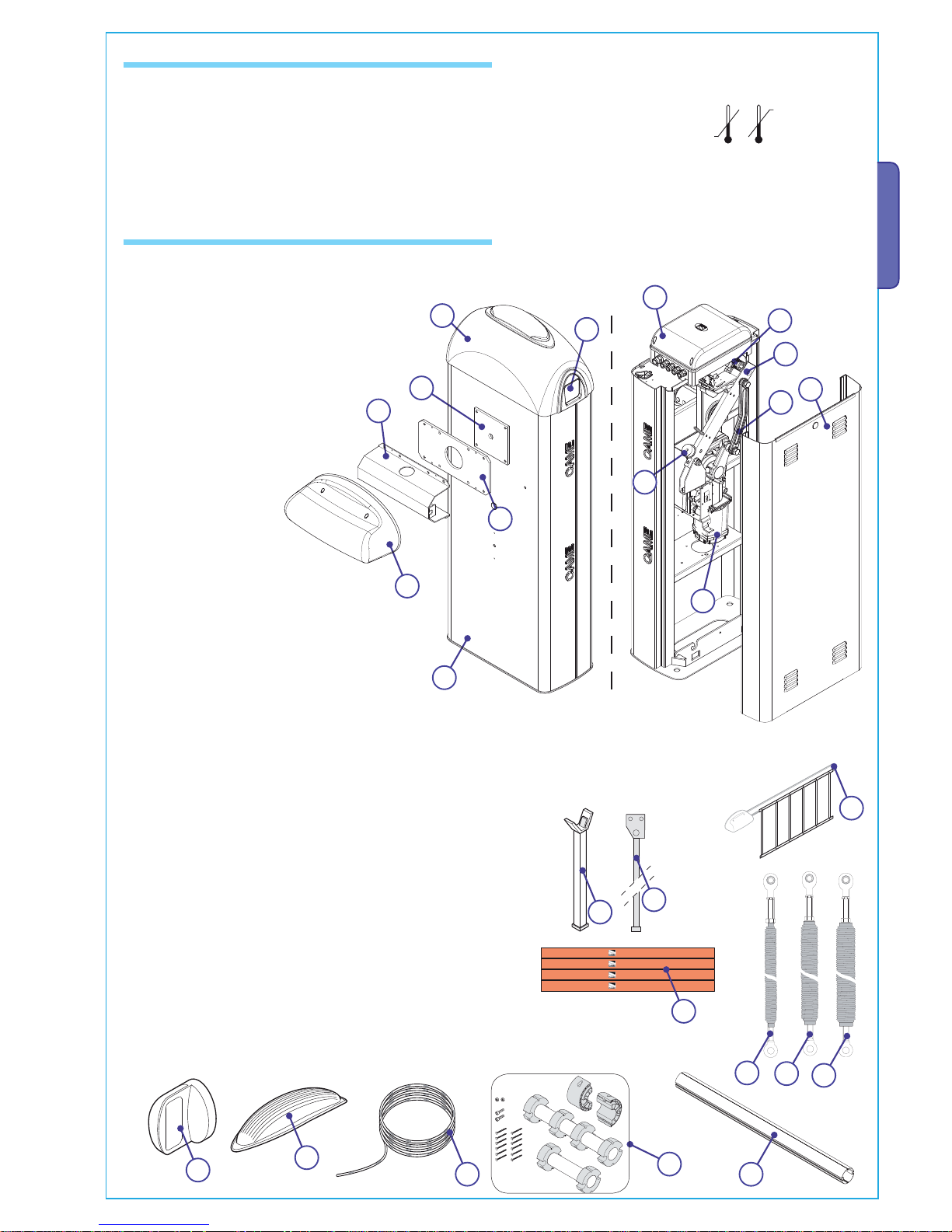
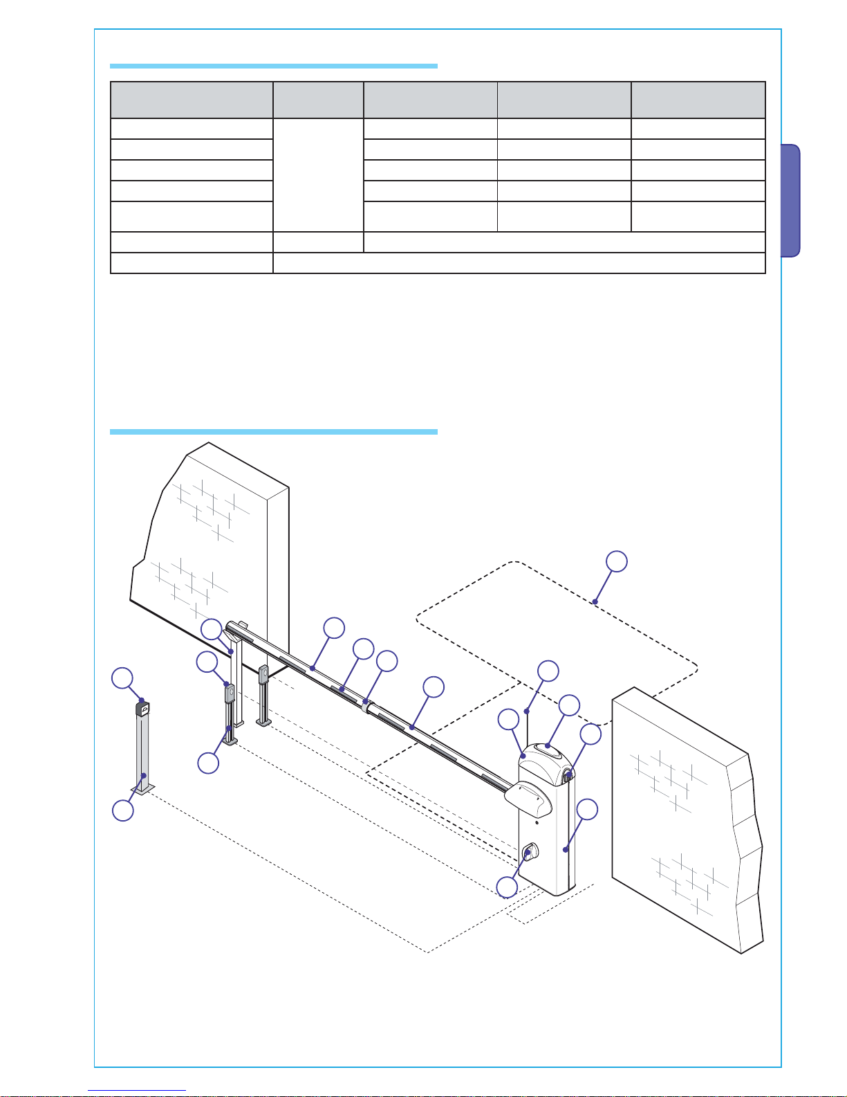
4.3 Parts description
AUTOMATION UNIT
VIEW FROM THE BAR
SUPPORT BRACKET
VIEW FROM IN-
SPECTION HATCH
ACCESSORIES
1) G02000/G04000 - Aluminium bar, painted white, Ø 100 mm
2) G02040 - Ø40 (yellow) balancing spring
3) G04060 - Ø50 (green) balancing spring
4) G06080 - Ø55 (red) balancing spring
5) G02806 - Rack
6) G02802 - Support for DIR photoelectric cells
7) G028401 - Luminous cord
8) G02807 - Fixed barrier support
9) G02808 - Mobile barrier support
10) G02809 - Adhesive reflector strips
11) G02801 - Flashing dome lamp
12) G06803 - Telescopic joint and additional insert to attach the
bar.11 -
1) Upper dome
2) Bar beam plate
3) Bar fitting intermediate plate
4) Cover for aluminium bar
5) Anti-shearing protection cover
6) Galvanized steel cabinet
7) Features for housing accessories
8) End-stop assembly
9) Lever arm
10) Transmission rod
11) Inspection hatch
12) Bar position adjustment
bu ers
13) Gearmotor
14) Control panel
Page 4
MAX
Pag.
4
- Manual code:
119G U44
119 GU 44 ver.
0.4
0.4 01/2012 © CAME cancelli automatici s.p.a. - The data and information reported in this installation manual are susceptible to change at any time and without obligation on CAME cancelli automatici s.p.a. to notify users.
ENGLISH
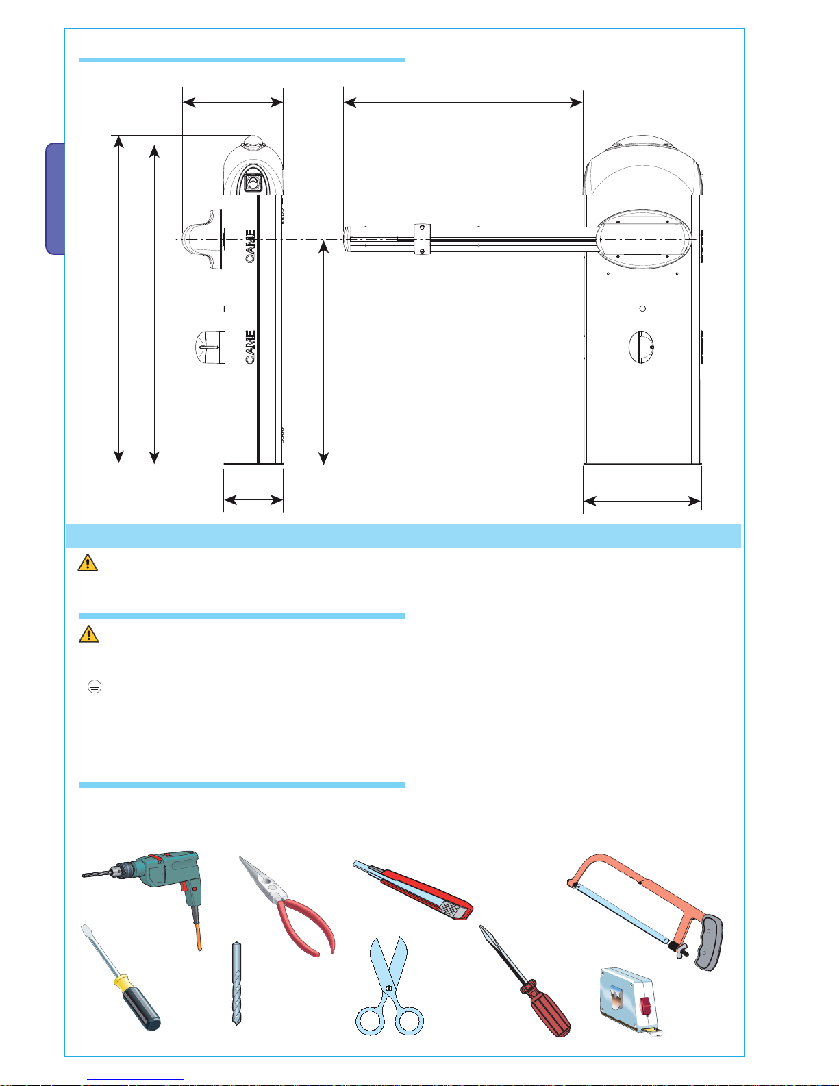
Make sure all tools and materials necessary are within reach to install the edge in maximum safety, according to regulations in
force. The following figure illustrates the minimum equipment for the installer.
Before proceeding with the installation, it is necessary to:
• Make sure the area selected for the mounting of the base and for the unit itself presents no hazards;
• Provide for suitable omnipolar disconnection device with more than 3 mm between contacts to section power supply;
•
Connections inside the case made for protection circuit continuity are allowed as long as they include additional insulation with
respect to other internal drive parts;
• Install suitable tubes and ducts for electric cable passage to guarantee protection against mechanical damage;
Installation must be carried out by expert qualified personnel and in full observance of regulations in force.
5 Installation
4.4 Size measurements
Measurements in mm
5.1 Preliminary checks
5.2 Tools and materials
Page 5
RX
TX
C
A
ME
CAM
E
2
1
7
3
4
5
6
8
9
10
11
12
13
14
15
16
Pag.
5
-
Manual code
:
119G U44
119 GU 44 ver.
0.4
0.4 01/2012
© CAME cancelli automatici s.p.a. -
The data and information reported in this installation manual are susceptible to change at any time and without obligation on CAME cancelli automatici s.p.a. to notify users.
ENGLISH
N.B.: An evaluation of the size of the cables with lengths other than the data in the table must be made based on the e ective
absorption of the connected devices, according to the instructions indicated by the CEI EN 60204-1 standards.
For connections that require several loads on the same line (sequential), the size given on the table must be re-evaluated based on
actual absorption and distances.
12 - Command divices (Keyboard, magnetic key, card, etc.)
13 - Column for reader
14 - Joint for rod
15 - Antenne
16 - Key-operated selector switch
5.3 Cable list and minimun thickness
Connections Type of cable
Length of cable
1 < 10 m
Length of cable
10 < 20 m
Length of cable
20 < 30 m
Alimentazione 230V
FROR CEI 20-22
CEI EN
50267-2-1
3G x 1,5 mm
2
3G x 2,5 mm
2
3G x 4 mm
2
Photoelectric cells TX 2 x 0,5 mm
2
2 x 0.5 mm
2
2 x 0,5 mm
2
Photoelectric cells RX 4 x 0,5 mm
2
4 x 0,5 mm
2
4 x 0,5 mm
2
24V power supply accessory 2 x 0,5 mm
2
2 x 0,5 mm
2
2 x 1 mm
2
Safety and control divices 2 x 0,5 mm
2
2 x 0,5 mm
2
2 x 0,5 mm
2
Antenna connection RG58 max. 10m
Metallic mass detector (see documents provided with product)
5.4 Standar installation
1 - GARD unit
2 - Control panel
3 - Aluminium bar
4 - Red phosphorescent strips
5 - Luminous cord
6 - Movement-indicating flashing lamp
7 - Column for photoelectric cells
8 - Photoelectric cells
9 - Fixed barrier support
10 - Magnetic sensor
11 - Photoelectric cell support
Page 6
Pag.
6
- Manual code:
119G U44
119 GU 44 ver.
0.4
0.4 01/2012 © CAME cancelli automatici s.p.a. - The data and information reported in this installation manual are susceptible to change at any time and without obligation on CAME cancelli automatici s.p.a. to notify users.
ENGLISH
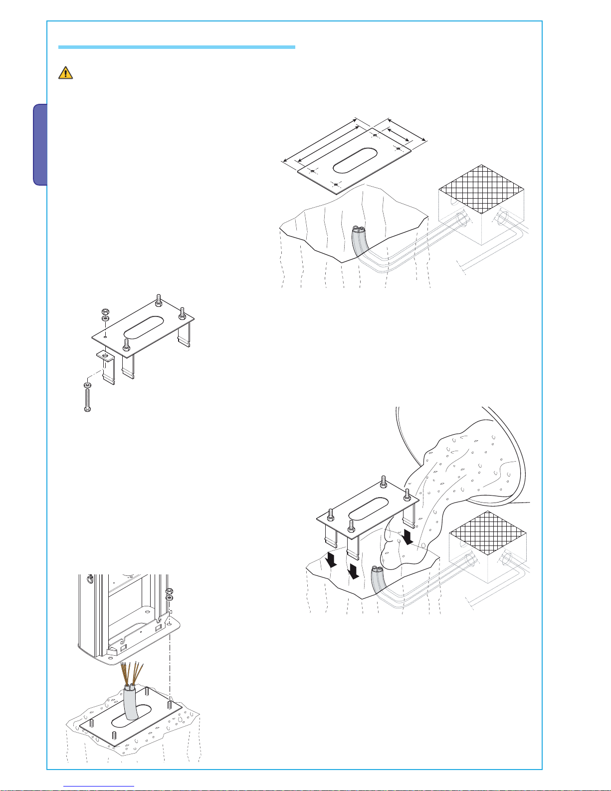
5.5 Fitting for unit base
The following applications are only examples, as the space required for unit installation and the accessories vary depending
on dimensions and therefore it is up to the installer to select the best solution.
- Assemble the four anchoring clamps at the base.
- Prepare a hole to house the fixing base and prepare
sheath tubes from the branch pit for the connections.
N.B. the number of tubes depends on the type of system
and the accessories you will hook up.
- Remove the nuts and washers from the threaded screws, position the cabinet on
the base in correspondence with the 4 threaded screws and secure with the nuts and
washers.
Note: We recommend installing the cabinet with the inspection hatch facing the internal
area.
- Fill the hole with concrete and immerge the clamps and the fixing
base, paying particular attention to the sheath tube which must
go through the hole at the base. The base must be perfectly level,
clean and with the screw threads fully on the surface.
Page 7
SX
DX
1
2
3
4
5
67
&#
&! &
Pag.
7
-
Manual code
:
119G U44
119 GU 44 ver.
0.4
0.4 01/2012
© CAME cancelli automatici s.p.a. -
The data and information reported in this installation manual are susceptible to change at any time and without obligation on CAME cancelli automatici s.p.a. to notify users.
ENGLISH
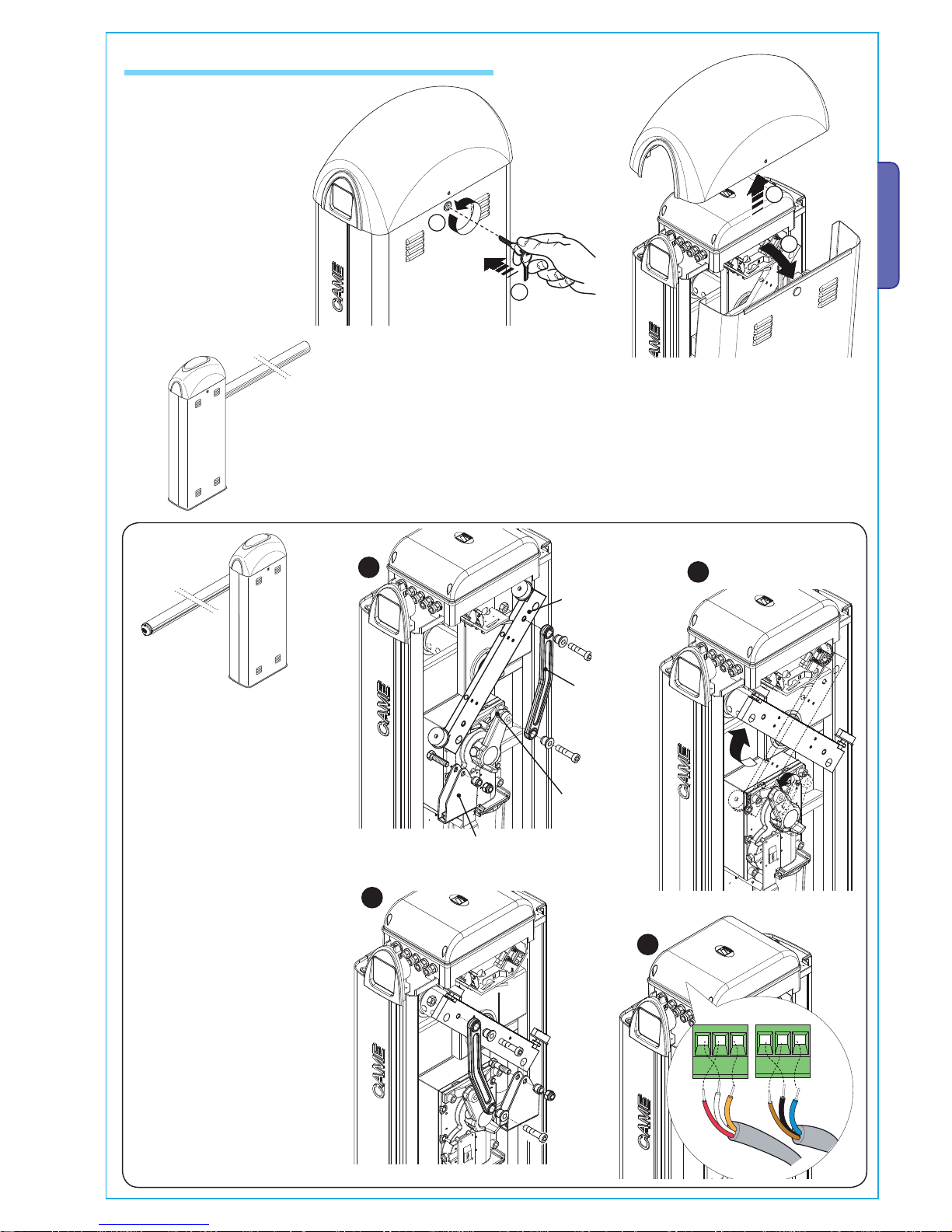
5.6 Installation of the Unit
- Remove the two screws
at the upper dome’s side
and lift it.
Insert the customised key
in the lock, turn it counter-
clockwise and remove the
hatch from the cabinet.
- The barrier is designed to be installed on the left of the gateway as
seen from inside.
Lever arm
Transmission rod
Spring securing bracket
Should installation on the right be
required, the direction of the bar’s
opening must be inverted. Proceed
in the following manner:
- remove the spring securing
bracket and the transmission rod
from the lever arm;
- loosen the motor support grub
screw;
- rotate the lever arm by 90°;
- Fix the spring securing bracket
and the transmission rod on the side
opposite that of lever arm;
- tighten the grub screw;
- invert the motor’s U-V phases and
the FA and FC endstop wires on the
control panel terminal.
Grub
Page 8
UNI5931 M8x20
UNI5931 M8x12
UNI6954 Ø2.9x13
UNI5931 M8x12
Pag.
8
- Manual code:
119G U44
119 GU 44 ver.
0.4
0.4 01/2012 © CAME cancelli automatici s.p.a. - The data and information reported in this installation manual are susceptible to change at any time and without obligation on CAME cancelli automatici s.p.a. to notify users.
ENGLISH
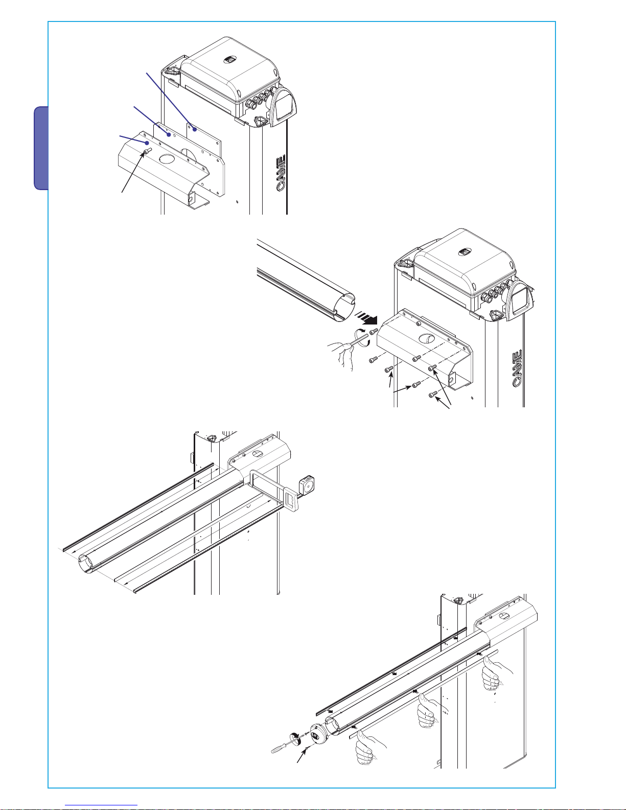
- Measure the length of the bar, cut the bar slot to the
same length.
- Position the middle plate between the fitting plate and the
bar-fitting cover, and put in one UNI 5931 M8x20 screw without tightening it to facilitate bar assembly.
Bar beam plate
Bar fi tting intermediate
plate
Bar fi tting cover
- Insert it in the bar’s conduit, a procedure that should be carried
out on both sides.
Insert the shock-resistant profile and cut excess length. Lastly,
secure the bar end plug with the screws provided.
- Insert the bar in the fitting cover and secure it with
screws.
Page 9
400 mm
UNI6954 Ø3.9x19
Pag.
9
-
Manual code
:
119G U44
119 GU 44 ver.
0.4
0.4 01/2012
© CAME cancelli automatici s.p.a. -
The data and information reported in this installation manual are susceptible to change at any time and without obligation on CAME cancelli automatici s.p.a. to notify users.
ENGLISH
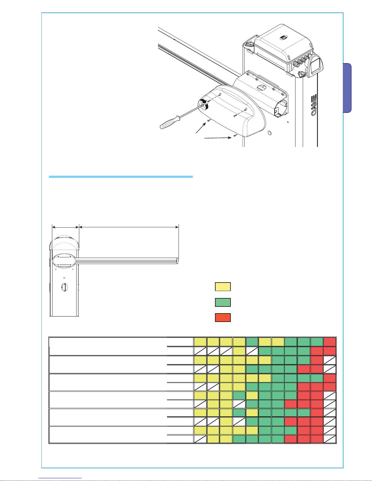
- Prior to bar balancing, select a suitable spring depending on the situation at
hand. See table below:
5.7 Bar balancing
PASSAGE CLEARANCE LAMP (max. 7.60 m)
SPRING TYPES
Spring G02040 Ø
e = 40 mm
Spring G04060 Ø
e = 50 mm
Spring G06080 Ø
e = 55 mm
- Tighten the anti-shearing protection cover
to the bar fitting with UNI6954 Ø3.9x19
screws.
* By Bare bar we mean a bar complete with the transparent slot cover and end plug.
Passage clearance lamp (m) 2.0
2.5
3.0
3.5
4.0
4.5
5.0
5.5
6.0
6.5
7.0
7. 6
Bare bar*
first spring
second spring
Bare bar* + mobile barrier support
first spring
second spring
Bare bar* + luminous cord
first spring
second spring
Bare bar* + luminous cord + mobile barrier support
first spring
second spring
Bare bar* + rack
first spring
second spring
Bare bar* + rack + luminous cord
first spring
second spring
Page 10

Pag.
10
10 - Manual code:
119G U44
119 GU 44 ver.
0.4
0.4 01/2012 © CAME cancelli automatici s.p.a. - The data and information reported in this installation manual are susceptible to change at any time and without obligation on CAME cancelli automatici s.p.a. to notify users.
ENGLISH
- Release the gearmotor and position the bar vertically, and then refasten
the gearmotor.
- Hook the tie rod to the anchoring racket.
Perform the same procedure if there is a second screw.
- Insert the UNI5739
M12X70 screw into the
spring securing bracket and
tighten the UNI5588 M12
nut to the screw (1-2).
Tighten the screw to spring
(2) and the tie rod to the
part underneath (3-4).
Page 11

Pag.
11
11 -
Manual code
:
119G U44
119 GU 44 ver.
0.4
0.4 01/2012
© CAME cancelli automatici s.p.a. -
The data and information reported in this installation manual are susceptible to change at any time and without obligation on CAME cancelli automatici s.p.a. to notify users.
ENGLISH
- Release the gearmotor and
manually turn the spring to
increase or decrease traction until
the bar rests at 45°.
- Tighten the blocking nut and refasten the gearmotor.
Note: make sure the spring functions properly:
- the spring is loose when the bar is in the vertical position (at rest)
- the spring is tight when the bar is in the horizontal position (tense).
- Perform any electrical connections to the control panel (see electrical
connections paragraph).
Page 12

^
^
Pag.
12
12 - Manual code:
119G U44
119 GU 44 ver.
0.4
0.4 01/2012 © CAME cancelli automatici s.p.a. - The data and information reported in this installation manual are susceptible to change at any time and without obligation on CAME cancelli automatici s.p.a. to notify users.
ENGLISH
5.8 End stop adjustment
Similarly, open the bar and adjust the free damper, to regulate the horizontal position (= closing).
If any adjustment of the vertical position (= opening) is needed, open the inspection
door and rotate the free damper clockwise (to increase the bar’s run) or counterclockwise (to decrease the run).
N.B.: perform this procedure after fi nishing the electrical connections.
Close the door and power up the system, activate the barrier to make sure it is parallel with the closed and at about 89° when open.
Warning! For greater safety and better unit performance, the bar’s opening and closing operations should be carried out with
the inspection hatch closed!
Page 13

:,
Pag.
13
13 -
Manual code
:
119G U44
119 GU 44 ver.
0.4
0.4 01/2012
© CAME cancelli automatici s.p.a. -
The data and information reported in this installation manual are susceptible to change at any time and without obligation on CAME cancelli automatici s.p.a. to notify users.
ENGLISH
- After bar opening and closing adjustment, tighten the
locking nuts under the dampers.
- ...place back the inspection door and the upper dome. Lock the door with the key.
- After making adjustments and settings from the control
panel, put the container lid in place and secure with
screws....
Page 14

Pag.
14
14 - Manual code:
119G U44
119 GU 44 ver.
0.4
0.4 01/2012 © CAME cancelli automatici s.p.a. - The data and information reported in this installation manual are susceptible to change at any time and without obligation on CAME cancelli automatici s.p.a. to notify users.
ENGLISH
WARNING! The release
procedure may constitute a
hazard for the user when,
for whatever reason – the
bar is fixed improperly to
the housing during assembly, or the bar is cracked or
broken in an accident, and
so on – the tension springs
no longer provide balance!
These can thus cause a
brusque rotation of the
bar attachment and/or of
the bar itself.
5.9 Manual release of the barrier
- Insert the key in the lock and turn it clock wise. Manually lift the bar and relock it by turning the key
counterclockwise.
6 Description control panel
This product is engineered and manufactured by CAME cancelli
automatici s.p.a. and complies with current safety regulations.
The control panel works on 230V a.c. of power, 50/60Hz
frequency.
Both command and control devices and accessories are 24V
powered.
Warning! Accessories must not exceed 40 W overall.
In case the endpoint assembly does not intervene, the card
nevertheless guarantees 20 seconds of operation. The card
autonomously handles the Encoder (obstacle sensitive) safety
function, which:
- when opening: the bar inverts the direction of travel until completely closed;
- when closing: the bar inverts the direction of travel until completely open.
Caution! after three consecutive direction reversals, the bar will
remain up and automatic closure will be discontinued. To close the
gate, use the radio remote control or the push-button.
All connections are protected by quick fuses, see table.
The card provides and controls the following functions:
- automatic closing after an open-command;
- immediate closure;
- pre-fl ashing by the motion indicator;
- obstacle detection when bar is still in any position.
The following command modes are possible:
- open/close;
- open/close and maintained action;
- Opening;
- Total stop.
Apposite trimmer regulate:
- the automatic closing run time;
Optional accessories:
- fl ashing crown and luminous band.
- bar open light marks the position of opening of the bar; it turns
o after the closing operation;
- the RSE card, in order to activate the compass function or
coupled through Dipswitches, see the relative technical literature.
Warning! Before acting on the machinery, cut off the main power
supply and disconnect any emergency batteries.
TECHNICAL FEATURES
Power supply 230 V - 50/60 Hz
max. rated power 400 W
Power draw when idling 25 W
Max power of 24V accessories 40 W
Insulation rating II
Material ABS
FUSES
protection: fuse type:
Electroblock
1.6 A-F
Electronic board
(power supply line)
5 A-F
Accessories 2 A-F
Control devices 630 mA-F
Page 15

5
67
&#
&!&
/.
%"
%"
63 #4 ,4
,4
).4%2",/##/
.
,
'.$
"!
$
%
6"
%
%
43
0
#
#
16
8315
18
9
1
13
12
11
10
17
14
2
6
5
19
4
6
20
7
21
5
67
&#
&!&
$
%
COM
NC
NC
COM
Pag.
15
15 -
Manual code
:
119G U44
119 GU 44 ver.
0.4
0.4 01/2012
© CAME cancelli automatici s.p.a. -
The data and information reported in this installation manual are susceptible to change at any time and without obligation on CAME cancelli automatici s.p.a. to notify users.
ENGLISH
Blue
Violet
Orange
White
Red
Brown
Black
Grey
6.1 Main components
6.2 Electrical connections
230V (a.c.) Motor
Gearmotor, mechanical stops
Opening-microswitch
Orange
Orange
Red
White
Blue
Black
Closing-microswitch
1 - Line fuse
2 - Control unit fuse
3 - Accessories fuse
4 - Electroblock fuse
5 - Powersource Terminals
6 - Transformer Terminals
7 - Electroblock Terminals
8 - Endpoint assembly Terminals
9 - Coupled Barrier Terminals
10- Encoder Terminals
11- Connections Terminals
12- Radiofrequency Card input (see table on page 20)
13- RSE serial card input (optional for connection coupled
barriers and/or compass)
14- TCA Trimmer: adjusts automatic closing time
15- Function selector Dip switch
16- Radio code storing buttons
17- Signalling LEDs for radio codes/automatic closing
18- Gate run counter
19- Motor Terminals
20- Transformer
21-Condenser
Brown
Red
Black
Condenser
Description of required electrical connections. If installing
on the right side, see page 7.
Page 16

%%430#
#
).4%2",/##/
.
,
%%43
+
-
%"
%"
6"
6
6"
6
Pag.
16
16 - Manual co de:
119G U44
119 GU 44 ver.
0.4
0.4 01/2012 © CAME cancelli automatici s.p.a. - The data and information reported in this installation manual are susceptible to change at any time and without obligation on CAME cancelli automatici s.p.a. to notify users.
ENGLISH
Terminals for powering the following accessories:
- 24V A.C. normally;
- 24V D.C. when the emergency batteries are working;
Maximum allowed power: 40W
Power supply for accessories
230V (a.c.) Power, 50/60Hz frequency
Cable lug with bolt and washer for
connecting to earth
Open barrier warning light (contact rating: 24V – 3W max.)
– Signals when bar is in ‘up’ position, turns o once bar is down
Luminous band (Contact rating: 24V-24W max.)
– Flashes when bar is closed or moving.
Warning devices
Flashing Crown (Contact rating: 24V – 8W max.)
– Flashes when bar is opening and closing.
Power out socket for electroblock, activated with opening command.
- VB2 , 24V electroblock powering (preset connection)
- VB1, 12V electroblock powering
Page 17

%%430#
#
%%430#
#
TX
RX
%%430#
#
Pag.
17
17 -
Manual code
:
119G U44
119 GU 44 ver.
0.4
0.4 01/2012
© CAME cancelli automatici s.p.a. -
The data and information reported in this installation manual are susceptible to change at any time and without obligation on CAME cancelli automatici s.p.a. to notify users.
ENGLISH
DIR photocells
Safety devices
Command devices
Stop button (N.C. Contact) - Bar stop barrier.Excludes automatic closing.
For movement to resume, press the command button or transmitter button. If unused,
set Dipswitch 6 to ON.
Opening button (N.O. contact) – Bar opening command.
Opening button (N.O. contact) - Opening command of the MASTER bar with coupled or
compass connection.
Closing button (N.O. contact) - Bar closing command. Obligatory in case of “maintained action” function.
Command button (N.O. contact) - Bar opening and closing command. By pushing the
button, the bar opens or inverts its movement depending on the selection made on
Dipswitch 2.
(N.O. contact) for “immediate closing”
- Automatic closing of the bar when obstacle passes in the
detection range of the safety devices.
(N.C.) contact for «re-open during closing phase»
- Input for EN 12978 standard-compliant safety devices
such as photocells. If contact is opened, while bar is
closing, the bar inverts its direction.
If unused, set DIP 7 switch to ON.
Page 18

5
67
%"
63 #4 ,4
,4
).4%2",/##/
.
,
'.$
"!
$
%
6"
/.
%%430#
#
&53)"),%M!
48
48
48
#
.#
(DIR)
Pag.
18
18 - Manual code:
119G U44
119 GU 44 ver.
0.4
0.4 01/2012 © CAME cancelli automatici s.p.a. - The data and information reported in this installation manual are susceptible to change at any time and without obligation on CAME cancelli automatici s.p.a. to notify users.
ENGLISH
6.4 Motor torque limiter
6.3 Electrical connection to operate the photocells’ safety test
To manage the performance surge, position dip switches n. 1 and n. 3 to ON: all 8 led indicator lights on the performance counter
light up.
Reset Dipswitch 3 to OFF and leave Dipswitch 1 in the ON mode, if you want to activate the automatic closing function.
6.5 Managing operational surge
Allows the control assembly to check the e ciency of the safety devices (photoelectric cells) after each opening or closing command.
A possible photoelectric cell malfunction is identifi ed with via LED
indicator fl ashing on the control panel, consequently cancelling any
remote control or pushbutton commands.
Electrical connection for safety test activation:
- photoelectric cell transmitters and receivers must be connected in
the following way (see scheme)
- turn dip-switch 8 to ON to carry out the test.
IMPORTANT:
When carrying out the safety test function, contacts N.C. if not used,
on the relative dip switches (see “functions selection” c. 6.9).
To vary the motor torque, move the shown faston (the one with
the black wire) to one of the 4 positions: 1 min – 4 max.
Page 19

/.
/.
/.
ON
OFF
/.
Pag.
19
19 -
Manual code
:
119G U44
119 GU 44 ver.
0.4
0.4 01/2012
© CAME cancelli automatici s.p.a. -
The data and information reported in this installation manual are susceptible to change at any time and without obligation on CAME cancelli automatici s.p.a. to notify users.
ENGLISH
6.8 Settings
- «A.C.T.» Sets the waiting time while open. Once this time has elapsed, closing automatically takes place. The waiting time
may be set from 1 to 120 seconds.
6.6 Operation counter
Led n°1 = 5000 operation
Led n°2 = 10000 operation
Led n°3 = 25000 operation
Led n°4 = 50000 operation
Led n°5 = 100000 operation
Led n°6 = 250000 operation
Led n°7 = 500000 operation
Led n°8 = 1000000 operation
6.7 Function selector
Default Setting
Visual count of the number of gate runs through the 8 LEDs, to zero-set the count, set Dipswitch 1 to OFF (if it is set to ON) and
Dipswitch 3 to ON, press CH1 button and wait for all LEDs to turn o . Once zeroed out, reset Dipswitch 1 to ON (if selected) and
Dipswitch to OFF.
1 ON - Automatic Closing - The automatic closing timer activates at the end of the opening gate run. The pre-set time is adjustable,
and is in any case conditioned by the activation of any safety devices, and does not activate after a total safety “stop” or
during a blackout (1 OFF - deactivated);
2 OFF - "Open-close" function with [2-7] button and radio transmitter ((fi tted with inserted radiofrequency card).
2 ON - "Open only" function with radio transmitter ((fi tted with inserted radiofrequency card).
3 ON - Maintained Action – barrier works by keeping the button pressed, one button 2-3 for opening, and one 2-4 for closing
(this excludes functioning of the radio transmitter).
4 ON - Pre-fl ashing while opening and closing – Following an opening or closing command, the fl asher and/or luminous crown
connected on [10-E7-/10-E6], fl ashes for 5 seconds before beginning its action.
5 ON - Obstacle detected - When motor is stopped (bar closed or after a total stop command) it prevents any movement if safety
devices, such as photocells, detect any obstacles.
6 OFF - Total stop - This function stops the bar and consequently excludes any automatic closing cycle; to set in motion again, use
either the keypad or transmitter. Insert the safety device in [1-2]; If unused, set DIP switch to ON.
7 OFF - Opening during closing - If the photocells detect an obstacle during bar is closing, gate motion is inverted until fully opened;
connect the safety device to terminals [2-C1]; if unused, set DIP switch to ON;
8 ON - Functioning of the photocells’ safety test - Allows the card to check the efficiency of any safety devices (i.e. photocells)
after every opening or closing command; (8 OFF deactivated).
9 OFF - Encoder activated – to detect obstacles; (9 ON deactivated)
10 - If unused, set the DIP switch to OFF.
Page 20

/.
Pag.
20
20 - Manual code:
119G U44
119 GU 44 ver.
0.4
0.4 01/2012 © CAME cancelli automatici s.p.a. - The data and information reported in this installation manual are susceptible to change at any time and without obligation on CAME cancelli automatici s.p.a. to notify users.
ENGLISH
7 Activating the radio command
AF Card
Connect the antenna’s RG58 cable to the apposite terminals.
Antenna
Insert the radio frequency card into the electronic card AFTER DISCONNECTING THE POWER (and disconnecting any batteries).
N.B.: the electronic card picks up the radiofrequency card on when it is running on power.
Radiofrequency card
Frequency-MHz radiofrequency
card
Series of
transmitters
FM 26.995 AF130 TFM
FM 30.900 AF150 TFM
AM 26.995 AF26 TOP
AM 30.900 AF30 TOP
AM 40.685 AF40 TOUCH
AF43 S / AF43 SM TAM / TOP
AF43SR ATOMO
AF43S / AF43TW TWIN
AM 868.35 AF868 TOP
Page 21

CAME
CAME
CAME
CAME
CAME
CAME
TOUCH
TCH 4024 • TCH 4048
TOP
TOP-432NA • TOP-434NA
TOP-432S
TOP
TOP-302A • TOP-304A
TOP
TOP-432A • TOP-434A
TAM
T432 • T434 • T438
TAM-432SA
TFM
T132 • T134 • T138
T152 • T154 • T158
CAME
CAME
CA
ME
ATOMO
AT01 • AT02
AT04
TWIN
TWIN2 • TWIN4
CAME
CAME
CAME
CAME
CAME
CAME
CAME
Pag.
21
21 -
Manual code
:
119G U44
119 GU 44 ver.
0.4
0.4 01/2012
© CAME cancelli automatici s.p.a. -
The data and information reported in this installation manual are susceptible to change at any time and without obligation on CAME cancelli automatici s.p.a. to notify users.
ENGLISH
Transmitters
See instruction sheet in AF43SR radiofrequency card box
See attached instructions
Page 22

CH1
CH2
T1
T2
Pag.
22
22 - Manual code:
119G U44
119 GU 44 ver.
0.4
0.4 01/2012 © CAME cancelli automatici s.p.a. - The data and information reported in this installation manual are susceptible to change at any time and without obligation on CAME cancelli automatici s.p.a. to notify users.
ENGLISH
AF Card
- Keep the “CH1” button on the electronic card pressed. The LED fl ashes.
- Press the transmitter button you wish to memorise. The LED will stay on to show memorisation has been successful.
LED flashing
Memorisation
CH1 = Channel for direct command to a function of the the gearmotor’s card, (“open only / “open-close” command, depending on
the choice made on DIP switch 2).
CH2 = Channel for direct commands with an accessory device (radio control with combined barrier connection or with bush).
- Repeat the points 1 and 2 procedures for the “CH2” button associating this to another button on the transmitter.
LED on
Page 23

28
#
!
-
%
#!-
%
48
Pag.
23
23 -
Manual code
:
119G U44
119 GU 44 ver.
0.4
0.4 01/2012
© CAME cancelli automatici s.p.a. -
The data and information reported in this installation manual are susceptible to change at any time and without obligation on CAME cancelli automatici s.p.a. to notify users.
ENGLISH
8 Safety instructions
This product must only be employed for its originally intended use. Any other use is wrong and potentially dangerous. The manufacturer cannot be held liable for any damages resulting from wrongful, erroneous or negligent uses.
Avoid using near mechanical moving parts. Stay out of the opening/closing arc when operator is in motion.
Do not exercise force against the motion of the operator as this could result in potentially dangerous situations.
Do not allow children to play or loiter within the opening/closing arc of the operator. Keep remote controls and any other command
device out the reach of children, to prevent operator from being activated by accident.
In the event of anomalous behaviour, stop using the operator immediately.
Important safety instructions
9 Maintenance
9.1 Periodic maintenance
Periodic maintenance to be carried out by the end-user is as follows: wipe clean
the glass surface of the photocells; check that the safety devices work properly; remove
any obstructions.
We suggest checking the state of lubrication and tightness of the anchoring screws on
the operator.
-To check the efficiency of the safety devices, move an object in front of the photocells
when gate is closing. If the operator inverts the motion or stops, the photocells are
working properly.
This is the only maintenance procedure to be carried out with the power source connected.
-Before performing any maintenance procedures, cut off the main power, to prevent possible accidents due to gate movement.
-To clean the photocells use a water dampened cloth. Do not use solvents or other chemical products which may ruin the devices.
-In the event of any strange vibrations or squeaking, lubricate the joints with grease, as
shown in the diagram.
Danger of crushing hands Danger! High voltage No transit during operation
Page 24

Pag.
24
24 - Manual code:
119G U44
119 GU 44 ver.
0.4
0.4 01/2012 © CAME cancelli automatici s.p.a. - The data and information reported in this installation manual are susceptible to change at any time and without obligation on CAME cancelli automatici s.p.a. to notify users.
ENGLISH
Periodic maintenance log for end-user (every 6 moths)
Date Notes
Signature
Page 25

Pag.
25
25 -
Manual code
:
119G U44
119 GU 44 ver.
0.4
0.4 01/2012
© CAME cancelli automatici s.p.a. -
The data and information reported in this installation manual are susceptible to change at any time and without obligation on CAME cancelli automatici s.p.a. to notify users.
ENGLISH
9.2 Extra-ordinary maintenance
The following table serves to note down any extraordinary maintenance, repairs or improvements performed by specialised
firms.
N.B.: Any extraordinary maintenance must be performed by specialised technicians.
Extra-ordinary maintenance log
Installer’s stamp Operator name
Date of job
Technician’s signature
Requester’s signature
Job performed ________________________________________________________________________________________
__________________________________________________________________________________________________
__________________________________________________________________________________________________
Page 26

Pag.
26
26 - Manual code:
119G U44
119 GU 44 ver.
0.4
0.4 01/2012 © CAME cancelli automatici s.p.a. - The data and information reported in this installation manual are susceptible to change at any time and without obligation on CAME cancelli automatici s.p.a. to notify users.
ENGLISH
MALFUNCTIONS REFERENCES CHECKS
The unit neither opens nor shuts 1-2-3-4-6-8-20 1 - Use key to lock trap door
The unit opens but does not close 4-7-10 2 - Disable “steady movement” with dipswitch
The unit shuts but does not open 4-7-9 3 – Check power supply and fuses
No automatic closure 11-12-13 4 - N.C. safety contacts open (1-2 / 2-C1)
The unit does not work if the remote control is
used
2-14-16 6 - Disable master-slave function
The unit inverts direction 7 7 – Check spring tension and balancing
The unit works only with remote control 22 8 – Disable obstacle detection with dipswitch
The photoelectric cell does not react 12-23-24 9 – Check if end stop opens
The signalling LED indicator flashes rapidly 4 10 – Check if end stop closes
The signalling LED indicator remains on 13 11 - Activate “automatic closure” dip switch
The unit does not end its run 7 12 – Check the correct direction of movement
The bar is not properly balanced 7-15 13 - (2-3 / 2-4 / 2-7) command button
14 -Check jumper on AF43S, turn on/off power
15 – Check the bar length ratio with mountable accessories
16 – Re-save radio code
20 - Raise the motor torque
22 - Enter or duplicate the same code in all the remote
controls
23 - Activate the photoelectric cell with the dipswitch
24 - Connect the photoelectric cells in a series, not in
parallel
9.3 Problem solving
In its premises, CAME CANCELLI AUTOMATICI S.p.A. implements an Environmental Management System certifi ed in com-
pliance with the UNI EN ISO 14standard to ensure environmental protection.
Please continue our e orts to protect the environment—which CAME considers one of the cardinal elements in the development of
its operational and market strategies—simply by observing brief recommendations as regards disposal:
DISPOSAL OF PACKAGING
I The packaging components (cardboard, plastic, etc.) are all classifi able as solid urban waste products and may be disposed of
easily, keeping in mind recycling possibilities.
Prior to disposal, it is always advisable to check specifi c regulations in force in the place of installation.
PLEASE DISPOSE OF PROPERLY!
PRODUCT DISPOSAL
IOur products are made up of various types of materials. Most of them (aluminium, plastics, iron, electrical wires, etc.) may be disposed of in normal garbage collection bins and can be recycled by disposing of in specifi c recyclable material collection bins and
disposal in authorized centres. Other components (electrical boards, remote control batteries, etc.), however, may contain polluting
substances. They should therefore be removed and given to qualifi ed service companies for proper disposal.
Prior to disposal, it is always advisable to check specifi c regulations in force in the place of disposal.
PLEASE DISPOSE OF PROPERLY!
10 Demolition and disposal
Page 27

Pag.
27
27 -
Manual code
:
119G U44
119 GU 44 ver.
0.4
0.4 01/2012
© CAME cancelli automatici s.p.a. -
The data and information reported in this installation manual are susceptible to change at any time and without obligation on CAME cancelli automatici s.p.a. to notify users.
ENGLISH
CE Compliance statement
Page 28

CAME
CAME
Fra nce
France
S.a.
S.a. FRANCE
7, Rue Des Haras
Z.i. Des Hautes Patures
92737
Nanterre Cedex
Nanterre Cedex
(+33) 0 825 825 874
(+33) 1 46 13 05 00
GERMANY
CAME Gmbh Seefeld
CAME Gmbh Seefeld
Akazienstrasse, 9
16356
Seefe ld
Seefeld Bei Berlin
(+49) 33 3988390
(+49) 33 39883985
CAME Automatismes S.a.
CAME Automatismes S.a. FRANCE
3, Rue Odette Jasse
13015
Marse ille
Marseille
(+33) 0 825 825 874
(+33) 4 91 60 69 05
U.A.E.
CAME Gulf Fze
CAME Gulf Fze
O ce No: S10122a2o210
P.O. Box 262853
Jebel Ali Free Zone -
Dubai
Dubai
(+971) 4 8860046
(+971) 4 8860048
CAME Automatismos S.a.
CAME Automatismos S.a. SPAIN
C/juan De Mariana, N. 17-local
28045
Madr id
Madrid
(+34) 91 52 85 009
(+34) 91 46 85 442
RUSSIA
CAME Rus
CAME Rus
Umc R us Llc
Umc Rus Llc
Ul. Otradnaya D. 2b, Str. 2, o ce 219
127273,
Mosco w
Moscow
(+7) 495 739 00 69
(+7) 495 739 00 69 (ext. 226)
CAME United King dom Ltd .
CAME United Kingdom Ltd. GREAT BRITAIN
Unit 3 Orchard Business Park
Town Street, Sandiacre
Notti ngham
Nottingham - Ng10 5bp
(+44) 115 9210430
(+44) 115 9210431
PORTUGAL
CAME Portugal
CAME Portugal
Ucj Portug al Unip esso al Lda
Ucj Portugal Unipessoal Lda
R
ua Liebig, nº 23
2830-141
Barre iro
Barreiro
(+351) 21 207 39 67
(+351) 21 207 39 65
CAME Group B enel ux S. a.
CAME Group Benelux S.a. BELGIUM
Zoning Ouest 7
7860
Le ssin es
Lessines
(+32) 68 333014
(+32) 68 338019
INDIA
CAME Indi a
CAME India
Aut omation S oluti ons P vt. Ltd
Automation Solutions Pvt. Ltd
A - 10, Green Park
110016 -
New D elhi
New Delhi
(+91) 11 64640255/256
(+91) 2678 3510
CAME Americas Aut omati on Ll c
CAME Americas Automation Llc U.S.A
11345 NW 122nd St.
Medle y
Medley, FL 33178
(+1) 305 433 3307
(+1) 305 396 3331
ASIA
CAME Asia Pacif ic
CAME Asia Pacific
60 Alexandra Terrace #09-09
B
lock C, The ComTech
118 502
Singa pore
Singapore
(+65) 6275 0249
(+65) 6274 8426
CAME Gmbh
CAME Gmbh GERMANY
Kornwestheimer Str. 37
70825
Korn tal
Korntal Munchingen Bei Stuttgart
(+49) 71 5037830
(+49) 71 50378383
CAME Cancell i Autom atici S.p.a.
CAME Cancelli Automatici S.p.a. ITALY
Via Martiri Della Libertà, 15
31030
Doss on Di Casier
Dosson Di Casier (Tv)
(+39) 0422 4940
(+39) 0422 4941
Informazioni Commerciali 800 848095
ITALY
CAME Sud s.r. l.
CAME Sud s.r.l.
Via F. Imparato, 198
Centro Mercato 2, Lotto A/7
80146
Napo li
Napoli
(+39) 081 7524455
(+39) 081 7529190
CAME Service I talia S.r.l.
CAME Service Italia S.r.l. ITALY
Via Della Pace, 28
31030
Doss on Di Casier
Dosson Di Casier (Tv)
(+39) 0422 383532
(+39) 0422 490044
Assis ten za Tecnica 800 295830
Assistenza Tecnica 800 295830
ITALY
CAME Global Util itie s s.r.l.
CAME Global Utilities s.r.l.
V
ia E. Fermi, 31
20060
Gessa te
Gessate (Mi)
(+39) 02 95380366
(+39) 02 95380224
09_2011
www.came.com www.came.it
Engli sh
English - Manual code:
119G U44
119 GU 44 ver.
0.4
0.4 01/2012 © CAME cancelli automatici s.p.a.
The data and information reported in this installation manual are susceptible to change at any time and without obligation on CAME cancelli automatici s.p.a. to notify users.
 Loading...