

Page 1
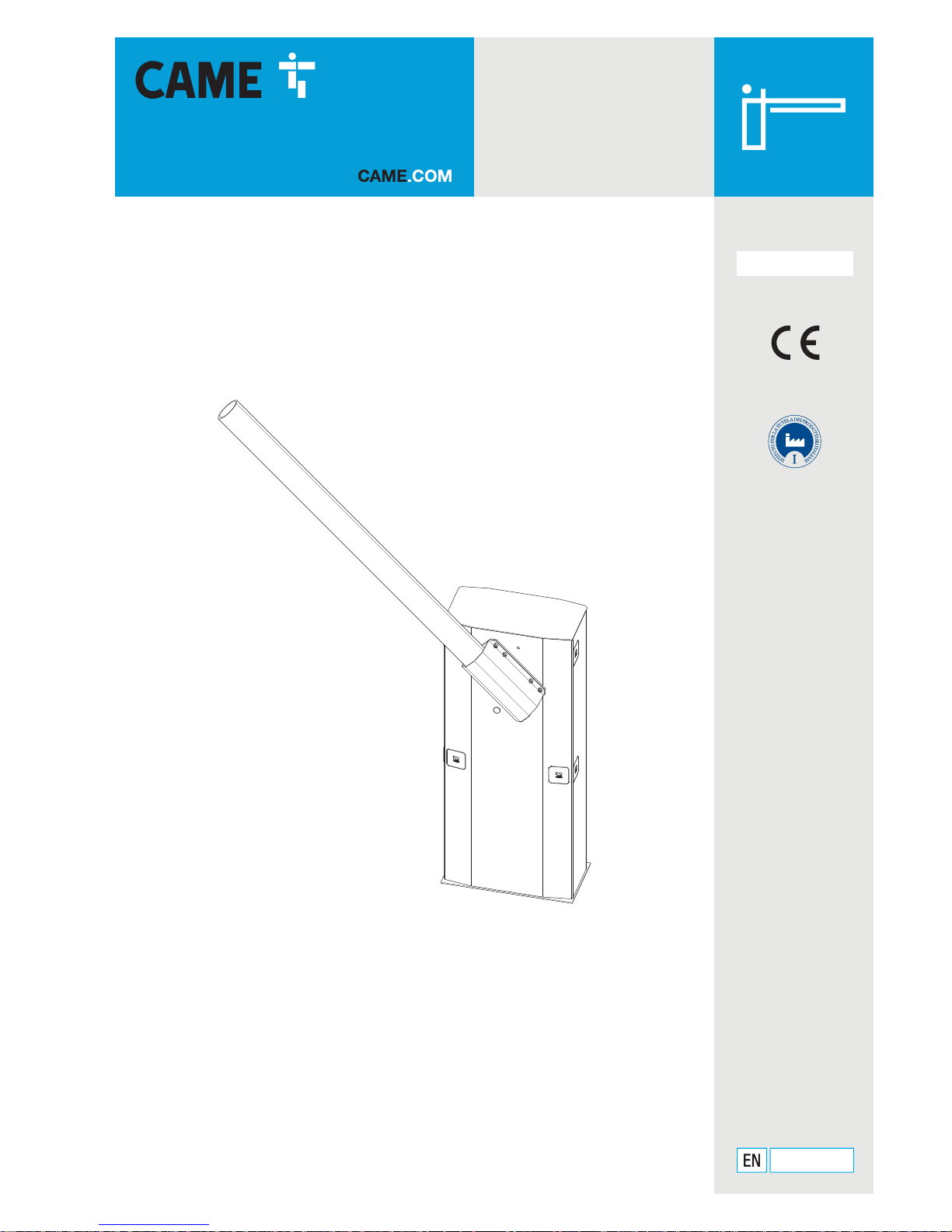
Automatic barrier
- GARD series
G5000
INSTALLATION OPERATION AND MAINTENANCE MANUAL
English
FA00571-EN
Page 2

p. 2 - Manual FA00571-EN v. 1 - 08/2017- © CAME S.p.A. - The contents of this manual may be changed, at any time, and without notice.
Page 3
CAME
C
A
ME
G5000
p. 3 - Manual FA00571-EN v. 1 - 08/2017- © CAME S.p.A. - The contents of this manual may be changed, at any time, and without notice.
GENERAL PRECAUTIONS FOR INSTALLERS
⚠CAUTION! Important safety instructions.
Carefully follow these instructions for the safety of people.
Keep these instructions.
BEFORE USING THIS PRODUCT, READ ALL ITS SAFETY PRECAUTIONS • THIS PRODUCT SHOULD ONLY BE USED FOR THE PURPOSE FOR WHICH IT WAS EXPLICITLY DESIGNED.
A
NY OTHER USE IS DANGEROUS. CAME S.P.A. IS NOT LIABLE FOR ANY DAMAGE CAUSED BY IMPROPER, WRONGFUL AND UNREASONABLE USE. • THIS PRODUCT SUPPLIED
BY CAME S.P.A. IS CONSIDERED TO BE "PAR TLY-COMPLETED MACHINERY", PURSUANT TO MACHINERY DIRECTIVE 2006/42/CE. PARTLY-COMPLETED MACHINERY
IS AN ASSEMBLY THAT ALMOST CONSTITUTES A MACHINE, BUT WHICH, ALONE, CANNOT ENSURE A CLEARLY DEFINED APPLICATION. PARTLY-COMPLETED MACHINERY IS
ONLY DESTINED TO BE INCORPORATED OR ASSEMBLED TO OTHER MACHINERY OR OTHER PART LY-COMPLETED MACHINES OR APPARATUSES TO BUILD A MACHINE REGULATED
BY DIRECTIVE 2006/42/CE. THE FINAL INSTALLATION MUST BE COMPLIANT WITH EUROPEAN DIRECTIVE 2006/42/CE AND EUROPEAN REFERENCE STANDARDS:
EN 13241-1, EN 12453, EN 12445
AND EN 12635 • IF THE BARRIER IS ONLY FOR REGULATING VEHICLE PASSAGES YOU MUST INSTALL A PEDESTRIAN
PASSAGEWAY NEAR THE OPERATOR ITSELF. SUITABLE SIGNS MUST BE AFFIXED AND CLEARLY VISIBLE TO WARN PEDESTRIANS IT IS FORBIDDEN TO TRANSIT THROUGH THE
DRIVEWAY. IF THE BARRIER IS FOR BOTH VEHICLES AND PEDESTRIANS, CARE MUST STILL BE EXERCISED WHEN TRANSITING THROUGH THE APERTURE. DRIVE OR WALK
THROUGH THE OPENING WHEN THE BARRIER IS STOPPED AND ENTIRELY RAISED AND AS FAR AS POSSIBLE FROM THE ROTATING FULCRUM OF THE BOOM • ALL SYSTEM
SETTING UP AND OPERATOR INSTALLATION TASKS MUST BE CONDUCTED EXCLUSIVELY BY QUALIFIED, EXPERT STAFF • AN IN-DEPTH REPORT ON ANY RESIDUAL RISKS
ASSOCIATED WITH THE INSTALLATION CAN BE REQUESTED FROM THE QUALIFIED, EXPERT STAFF, ALONG WITH INSTRUCTIONS ON HOW TO OPERATED THE CONTROL DEVICES
• M
AKE SURE YOU ARE GIVEN AND THAT YOU STORE ALL OPERATING MANUALS RELATED TO THE PRODUCTS THAT MAKE UP THE FINAL MACHINERY • IT IS FORBIDDEN
FOR USERS TO PERFORM ANY OPERATIONS WHICH ARE NOT EXPRESSLY MENTIONED OR REQUIRED OF THEM IN THE MANUALS FOR REPAIRS, SETTINGS AND EXTRAORDINARY
MAINTENANCE, PLEASE CONTACT THE TECHNICAL ASSISTANCE CENTER. • THIS APPARATUS MAY BE USED BY CHILDREN OF OVER EIGHT YEARS OF AGE AND BY PERSONS
THAT ARE PHYSICALLY, MENTALLY AND SENSORIALLY CHALLENGED, OR THAT HAVE NO EXPERIENCE OR KNOWLEDGE OF IT, PROVIDED THAT IT HAPPENS UNDER SUPERVISION,
OR AFTER BEING TRAINED ON HOW TO SAFELY OPERATE IT AND OF THE RISKS INVOLVED. • CHILDREN MUST NO PLAY WITH THE DEVICE OR ITS CONTROLS, INCLUDING
ANY TRANSMITTERS. • CHAPERON CHILDREN TO PREVENT CHILDREN FROM PLAYING WITH THE APPARATUS AND ITS CONTROLS • CLEANING AND MAINTENANCE BY USERS
MUST NOT BE PERFORMED BY UNSUPERVISED CHILDREN. • FREQUENTLY INSPECT THE INSTALLATIONS TO CHECK FOR SIGNS OF UNBALANCES OR WEAR-AND-TEAR. • DO
NOT USE IF REPAIRS OR SETTINGS ARE REQUIRED. • IF ANY REPAIRS OR CHANGES NEED TO BE MADE TO THE SYSTEM, RELEASE THE OPERATOR AND DO NOT USE IT UNTIL
SAFETY CONDITIONS ARE RESTORED BY QUALIFIED, EXPERT STAFF. • CUT OFF THE ELECTRIC POWER BEFORE RELEASING THE OPERATOR FOR MANUALLY OPENING THE GATE,
AND BEFORE ANY PROCEDURE, TO PREVENT ANY HAZARDOUS SITUATIONS. READ THE INSTRUCTIONS • IF THE POWER-SUPPLY CABLE IS DAMAGED, IT MUST BE IMMEDIATELY
REPLACED BY THE MANUFACTURER OR BY AN AUTHORIZED TECHNICAL ASSISTANCE CENTER, OR IN ANY CASE, BY QUALIFIED STAFF, TO PREVENT ANY RISK • KEEP AWAY
FROM AND DO NOT LOITER NEAR THE BARRIER AND MECHANICAL MOVING PA RTS • DO NOT ENTER THE BARRIER'S AREA OF OPERATION WHEN IT IS MOVING • DO NOT
COUNTER THE OPERATOR'S MOVEMENT AS THIS COULD RESULT IN DANGEROUS SITUATIONS • ALWAYS PAY SPECIAL ATTENTION TO ANY DANGEROUS POINTS, WHICH HAVE
TO BE LABELED WITH SPECIFIC PICTOGRAMS AND/OR BLACK AND YELLOW STRIPES • WHEN USING A SELECTOR OR CONTROL IN MAINTAINED-ACTION MODE, ALWAYS CHECK
THAT THERE ARE NO PEOPLE LOITERING IN THE AREA OF OPERATION OF THE MOVING PART S, UNTIL THE CONTROL IS RELEASED • THE BARRIER MAY MOVE AT ANY TIME AND
WITHOUT WARNING IF REMOTE CONTROLS ARE BEING USED OR THE AUTOMATIC CLOSING IS ACTIVATED • IT IS FORBIDDEN TO ACCESS ANY PROTECTED INTERNAL PA RTS .
• T
HE DEVICE EMITS A LEVEL OF ACOUSTIC PRESSURE EQUAL OR INFERIOR TO 70 DB (A). • IN CASE OF ANY MALFUNCTION OR STRUCTURAL DAMAGE, IMMEDIATELY
STOP OPERATION AND CALL FOR QUALIFIED TECHNICAL ASSISTANCE. • DO NOT ACTIVATE THE OPERATOR IF PEOPLE, PETS OR OBJECTS ARE OBSTRUCTING THE PASSAGE.
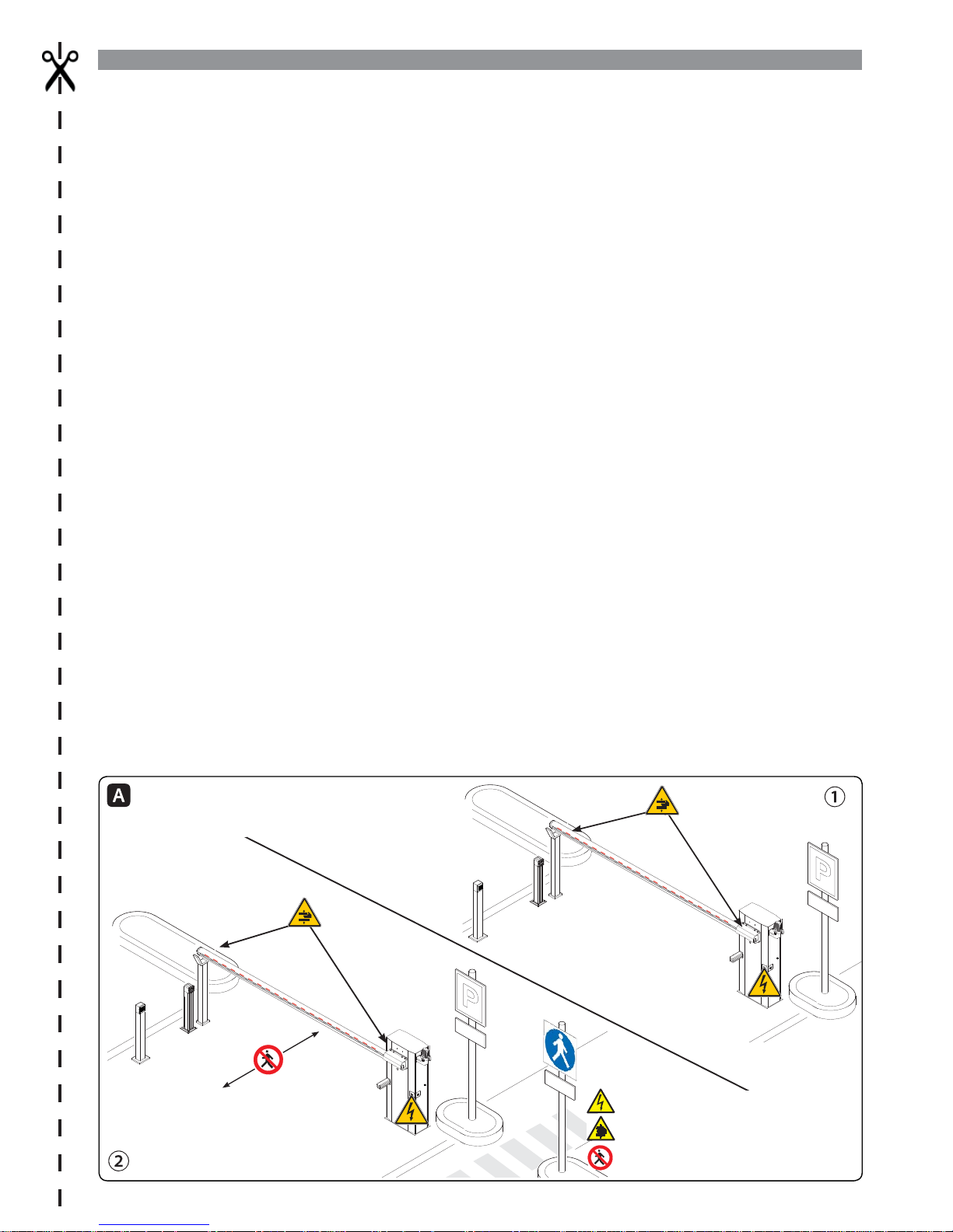
T
HE FIGURE SHOWS SHOWS TWO STANDARD INSTALLATIONS: ① VEHICLES AND PEDESTRIANS AND ②VEHICLES ONLY. THE MAIN HAZARD POINTS FOR PEOPLE ARE
SHOWN.
DANGER OF HIGH VOLTAGE
DANGER OF HAND ENTRAPMENT.
DO NOT ENTER
Page 4
p. 4 - Manual FA00571-EN v. 1 - 08/2017- © CAME S.p.A. - The contents of this manual may be changed, at any time, and without notice.
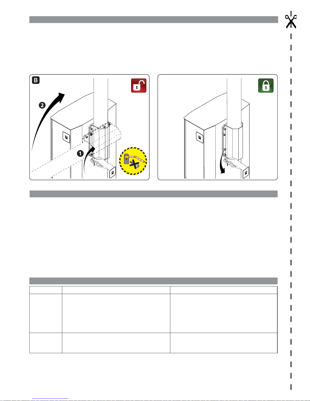
MANUAL RELEASE
Warning! This operation is potentially hazardous for user, when for whatever reason, such as the boom being badly fastened, ripped
out or broken during an accident, and so on, the loosened springs no longer provide the proper balancing action. This could lead to a
sudden rotation of the boom attachment and/or of the boom itself.
RELEASING (fi gure )
Fit the key into the lock, turn it clockwise and manually raise the boom.
LOCKING (fi gure )
To lock the boom back into place, turn the key counter-clockwise.
MAINTENANCE
⚠
WHEN CLEANING, MAINTAINING AND REPLACING PARTS, DISCONNECT THE OPERATOR FROM THE MAINS POWER
SUPPLY (EXCLUDING POINT B)
At least every six months, perform ordinary maintenance jobs.
⚠ When performing this procedure, keep clear of the movement of the boom.
A - Wipe clean the photocells' glass with a soft, slightly water-dampened cloth. Do not use any solvents or other chemicals.
B - Check that the photocells are working properly by waving an object between them when the boom is moving: if the boom inverts its
direction or the maneuver is stopped, the photocells are working properly.
C - Check that there are no impediments to the proper operation of the operator, such as any overgrown vegetation that could block the
photocells or any changes or yielding to the barrier's structure.
Any repairs, or changes to the installation must be performed by qualifi ed sta and all jobs logged carefully.
WHAT TO DO IF ...
ISSUES POSSIBLE CAUSES POSSIBLE FIXES
The barrier
neither opens
nor closes
• Power supply is missing
• The gearmotor is stuck
• The transmitter emits a weak or inexistent signal
• Inspection hatch is open
• Button/s and/or selectors stuck
• Check main power supply
• Lock the gearmotor
• Replace the batteries
• Check that the inspection hatch is closed and locked
• Check that the devices and the electric cables are in
proper working conditions
The barrier
opens but does
not close
• The photocells are working • Check that there are no obstructions in the range of
operation of the photocells
⚠ If the problem cannot be solved by following the fi xes in the table or if any malfunctions, anomalies, noises, vibrations or
suspicious and unexpected behavior is experienced on the system, call for qualifi ed assistance.
Page 5

p. 5 - Manual FA00571-EN v. 1 - 08/2017- © CAME S.p.A. - The contents of this manual may be changed, at any time, and without notice.
GENERAL PRECAUTIONS FOR INSTALLERS
⚠ CAUTION! Important safety instructions.
Follow all of these instructions. Improper installation can cause serious bodily harm.
Before continuing, also read the general precautions for users.
THIS PRODUCT MUST ONLY BE USED FOR ITS SPECIFICALLY INTENDED PURPOSE. ANY OTHER USE IS DANGEROUS. CAME S.P.A. IS NOT LIABLE FOR ANY DAMAGE CAUSED
BY IMPROPER, WRONGFUL AND UNREASONABLE USE. • THIS MANUAL'S PRODUCT IS DEFINED BY MACHINERY DIRECTIVE 2006/42/CE AS "PAR TLY-COMPLETED
MACHINERY". PARTLY-COMPLETED MACHINERY IS A SET THAT ALMOST CONSTITUTES A MACHINE, BUT WHICH, ALONE, CANNOT ENSURE A CLEARLY DEFINED APPLICATION.
PARTLY-COMPLETED MACHINERY IS ONLY DESTINED TO BE INCORPORATED OR ASSEMBLED TO OTHER MACHINERY OR OTHER PAR TLY-COMPLETED MACHINERY OR APPARATUSES
TO BUILD MACHINERY THAT IS REGULATED BY DIRECTIVE 2006/42/CE. THE FINAL INSTALLATION MUST BE COMPLIANT WITH EUROPEAN DIRECTIVE 2006/42/CE
AND EUROPEAN REFERENCE STANDARDS: EN 13241-1, EN 12453, EN 12445 ED EN 12635. • GIVEN THESE CONSIDERATIONS, ALL PROCEDURES STATED
IN THIS MANUAL MUST BE EXCLUSIVELY PERFORMED BY EXPERT, QUALIFIED STAFF. • LAYING THE CABLES, INSTALLATION AND TESTING MUST FOLLOW STATE -OF-THE-ART
PROCEDURES AS DICTATED BY REGULATIONS • MAKE SURE THAT THE OPENING OF THE AUTOMATIC BARRIER DOES NOT CONSTITUTE A HAZARD • DO NOT INSTALL THE
OPERATOR ONTO SURFACES THAT COULD YIELD AND BEND. IF NECESSARY, ADD SUITABLE REINFORCEMENTS TO THE ANCHORING POINTS • CHECK THAT THE TEMPERATURE
RANGE APPEARING ON THE OPERATOR IS SUITED TO THE PLACE OF INSTALLATION • DO NOT INSTALL ON SLOPES (ONLY ON LEVEL SURFACES) • CHECK THAT OPERATOR
IS NOT SPRAYED FROM BELOW BY ANY SPRINKLERS • SUITABLY SECTION OFF AND DEMARCATE THE ENTIRE INSTALLATION SITE TO PREVENT UNAUTHORIZED PERSONS
FROM ENTERING THE AREA, ESPECIALLY MINORS AND CHILDREN. • BE CAREFUL WHEN HANDLING OPERATORS THAT WEIGH OVER 20 KG. IF NEED BE, USE PROPER
SAFETY HOISTING EQUIPMENT • PLEASE USE SUITABLE PROTECTIONS TO PREVENT ANY MECHANICAL HAZARDS WHEN PEOPLE ARE MOVING AROUND THE MACHINERY. •
ANY RESIDUAL RISKS MUST BE NOTIFIED BY PROPER, CLEARLY VISIBLE PICTOGRAMS, WHICH MUST BE EXPLAINED TO END USERS • FIT, IN PLAIN SIGHT, THE MACHINE'S
ID PLATE WHEN THE INSTALLATION IS COMPLETE • ALL COMMAND AND CONTROL DEVICES MUST BE INSTALLED AT LEAST 1.85 M FROM THE BOOM'S OPERATING
PERIMETER, OR, WHERE THEY ARE OUT OF REACH FROM OUTSIDE THE BARRIER • UNLESS THE KEY-OPERATION IS FUNCTIONING (FOR E.G. KEYPAD SELECTOR, KEY-SWITCH
SELECTOR, TRANSPONDER SELECTOR, AND SO ON), ANY MAINTAINED-ACTION CONTROL DEVICES MUST BE INSTALLED AT LEAST 1.5 M FROM THE GROUND AND OUT
OF REACH FROM UNAUTHORIZED USERS. • THE MANUFACTURER DECLINES ANY LIABILITY FOR USING NON-ORIGINAL PRODUCTS; WHICH WOULD RESULT IN WARRANTY
LOSS • ALL MAINTAINED-ACTION SWITCHES MUST BE FITTED SO AS TO BE CLEARLY VISIBLE FROM THE BOOM'S MANEUVERING AREA, AND YET WELL AWAY FROM ANY
MOVING PART S • AFFIX A PERMANENT TAG , THAT DESCRIBES HOW TO USE THE MANUAL RELEASE MECHANISM, CLOSE TO THE MECHANISM. • BEFORE HANDING OVER TO
USERS, CHECK THAT THE SYSTEM IS COMPLIANT WITH THE 2006/42/CE UNIFORMED MACHINERY DIRECTIVE. MAKE SURE THE SETTINGS ON THE OPERATOR ARE ALL
SUITABLE AND THAT ANY SAFETY AND PROTECTION DEVICES, AND ALSO THE MANUAL RELEASE, WORK PROPERLY. • IF THE POWER-SUPPLY CABLE IS DAMAGED, IT MUST
BE IMMEDIATELY REPLACED BY THE MANUFACTURER OR BY AN AUTHORIZED TECHNICAL ASSISTANCE CENTER, OR IN ANY CASE, BY QUALIFIED STAFF, TO PREVENT ANY RISK
• DURING ALL PHASES OF THE INSTALLATION MAKE SURE YOU HAVE CUT OFF THE MAINS POWER SOURCE. • THE ELECTRICAL CABLES MUST RUN THROUGH THE CABLE
GLANDS AND MUST NOT TOUCH ANY HEATED PART S, SUCH AS THE MOTOR, TRANSFORMER, AND SO ON). • MAKE SURE YOU HAVE SET UP A SUITABLE DUAL POLE CUT OFF
DEVICE ALONG THE POWER SUPPLY THAT IS COMPLIANT WITH THE INSTALLATION RULES. IT SHOULD COMPLETELY CUT OFF THE POWER SUPPLY ACCORDING TO CATEGORY
III SURCHARGE CONDITIONS. • WHEN THE PASSAGE WIDTH CLEARANCE IS GREATER THAN 3 M, YOU MUST USE A FIXED REST FOR THE BOOM TO SUPPORT IT • IF THE
BARRIER IS FOR BOTH PEDESTRIANS AND VEHICLES, YOU MUST CHECK THAT IT IS COLLISION FORCE COMPLIANT PURSUANT TO STANDARDS EN12453 AND EN12445
• IF THE BARRIER IS ONLY FOR VEHICLES, YOU MUST SET UP A SUITABLE PEDESTRIAN PASSAGE NEAR THE VEHICLE ENTRY, AND POST SUITABLE SIGNAGE THAT PROHIBIT
TRANSIT OF PEDESTRIANS AND BICYCLES THROUGH THE OPENING • KEEP THE SECTION OF THIS MANUAL INSIDE THE TECHNICAL FOLDER ALONG WITH THE MANUALS OF
ALL THE OTHER DEVICES USED FOR YOUR AUTOMATION SYSTEM. REMEMBER TO HAND OVER TO THE END USERS ALL THE OPERATING MANUALS OF THE PRODUCTS THAT
MAKE UP THE FINAL MACHINERY.
T
HE FIGURE SHOWS (PAG E 3) SHOWS TWO STANDARD INSTALLATIONS: ① FOR PEDESTRIANS AND VEHICLES AND ②ONLY FOR VEHICLES. THE MAIN HAZARD
POINTS FOR PEOPLE ARE SHOWN.
Page 6

356
1077
450max. 4988
863
460 240
p. 6 - Manual FA00571-EN v. 1 - 08/2017- © CAME S.p.A. - The contents of this manual may be changed, at any time, and without notice.
KEY
This symbol shows which parts to read carefully.
⚠
This symbol shows which parts describe safety issues
☞
This symbol shows which parts to tell users about.
The measurements, unless otherwise stated, are in millimeters.
OPERATING LIMITS
Model G5000
Maximum clearance width of the passage (m) 5000
TECHNICAL DATA
Model G5000
Protection rating (IP) 54
Power supply (V - 50/60 Hz) 230 AC
Input voltage motor (V) 24 DC
Max draw (A) 15
Power rating (W) 200
Torque ( Nm) 600
Opening time (s) 4 ÷ 8
Cycles/hour
INTENSIVE USE
Operating temperature (°C) -20 to +55
Reduction ratio (i) 1/202
Apparatus class I
Weight (Kg) 78.5
DIMENSIONS
DESCRIPTION
Barrier made of varnished galvanized steel set up to fit accessories.
REQUEST EITHER LEFT OR RIGHT-HAND BARRIERS WHEN ORDERING. THE ILLUSTRATIONS IN THIS MANUAL ARE ALL FOR LEFT-
HAND BARRIERS!
INTENDED USE
The automatic barrier is designed for private and public parking facilities.
Any installation and/or use other than that specified in this manual is forbidden.
Page 7
CAME
p. 7 - Manual FA00571-EN v. 1 - 08/2017- © CAME S.p.A. - The contents of this manual may be changed, at any time, and without notice.
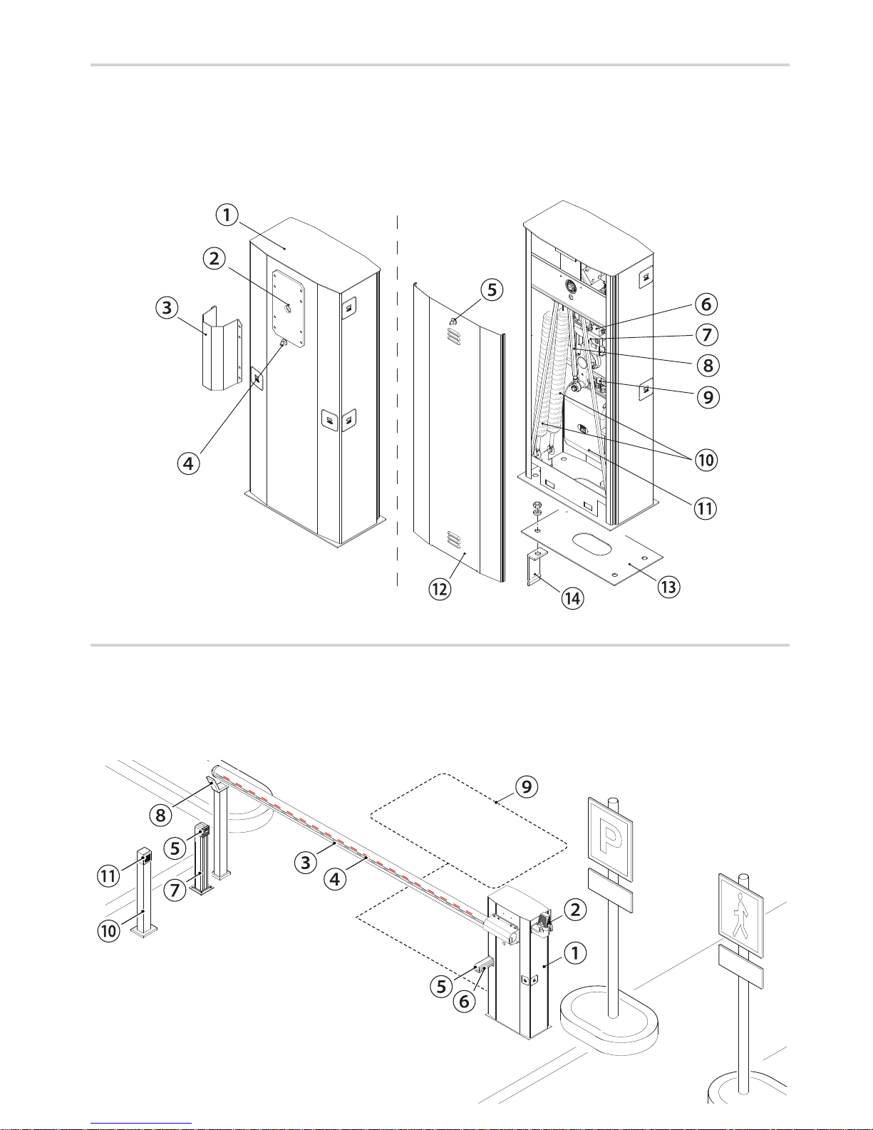
STANDARD INSTALLATION
1. Barrier with boom
2. Flashing light
3. Luminous cord
4. Reflective strips
5. Photocells
6. Photocell casing
7. Small photocell post
8. Fixed rest
9. Coil
10. Control device post
11. Control device (keypad selector, transponder sensor)
DESCRIPTION OF PARTS
1. Cabinet
2. Drive-shaft plate
3. Boom attachment-cover
4. Gearmotor release lock
5. Inspection-hatch lock
6. Gearmotor
7. Mechanical closing stop
8. Transmission lever
9. Mechanical opening stop
10. Balancing springs
11. Control panel
12. Inspection hatch
13. Anchoring plate
14. Anchoring bracket
Page 8
p. 8 - Manual FA00571-EN v. 1 - 08/2017- © CAME S.p.A. - The contents of this manual may be changed, at any time, and without notice.
GENERAL INSTRUCTIONS FOR INSTALLING
⚠
Only skilled, qualified staff must install this product.
PRELIMINARY CHECKS
⚠
Before beginning, do the following:
• make sure the plate is anchored to a solid spot;
• check that there are no obstruction or impediments near the cabinet;• set up suitable tubes and conduits for the electric cables to
pass through, making sure they are protected from any mechanical damage.
CABLE TYPES AND MINIMUM THICKNESSES
Connection
cable length
< 20 m 20 < 30 m
Input voltage for 230 V AC control board
(1P+N+PE)
3G x 1.5 mm
2
3G x 2.5 mm
2
Command and control devices 2 x 0.5 mm
2
Signaling devices 2 x 0.5 mm
2
TX Photocells 2 x 0.5 mm
2
RX photocells 4 x 0.5 mm
2
⚠
When operating at 230 V and outdoors, use H05RN-F-type cables that are 60245 IEC 57 (IEC) compliant; whereas indoors, use
H05VV-F-type cables that are 60227 IEC 53 (IEC) compliant. For power supplies up to 48 V, you can use FROR 20-22 II-type cables
that comply with EN 50267-2-1 (CEI).
To connect the antenna, use the RG58 (we suggest up to 5 m).
For paired, alternating or CRP connections, use a UTP CAT5 cable (up to 1,000 m long).
If cable lengths differ from those specified in the table, establish the cable sections depending on the actual power draw of the
connected devices and according to the provisions of regulation CEI EN 60204-1.
For multiple, sequential loads along the same line, the dimensions on the table need to be recalculated according to the actual
power draw and distances. For connecting products that are not contemplated in this manual, see the literature accompanying said
products
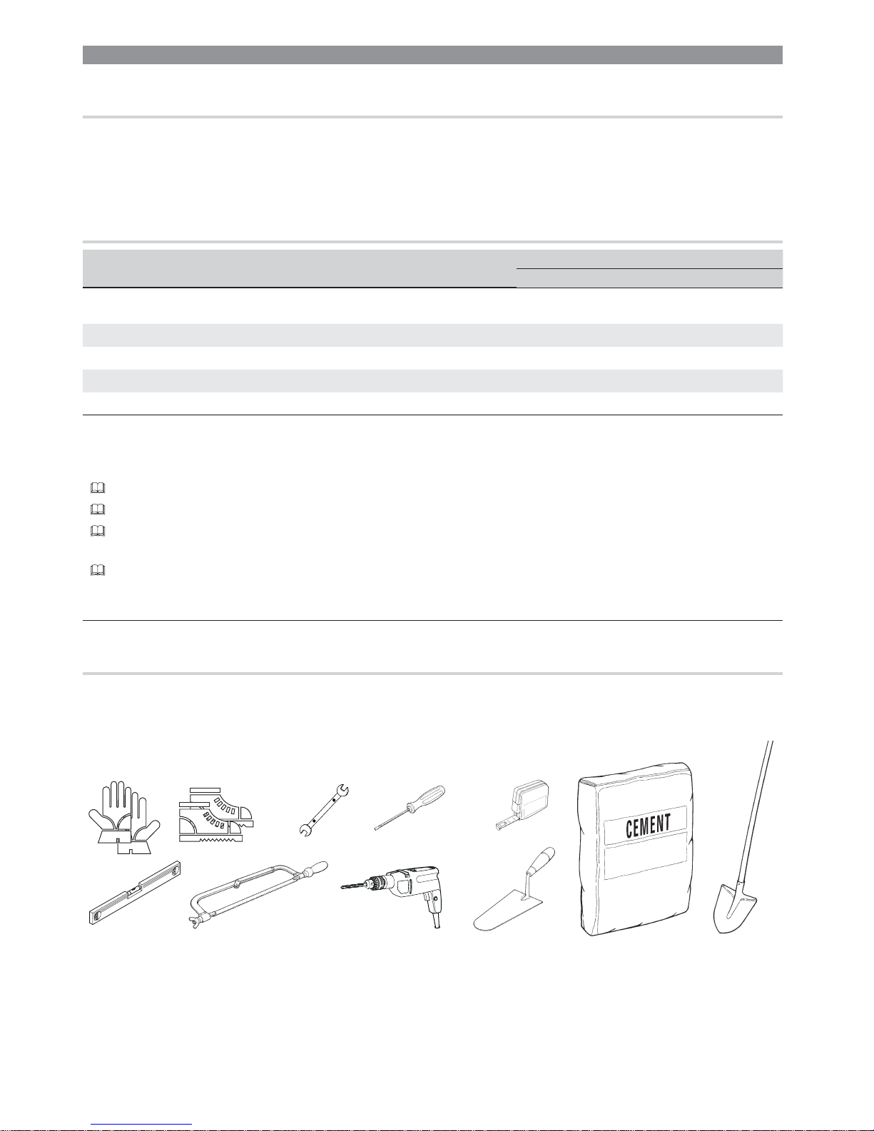
TOOLS AND MATERIALS
Make sure you have all the tools and materials you will need for installing in total safety and in compliance with applicable regulations.
The figure shows some of the equipment installers will need.
Page 9
400
700
500
460
380
240
140
p. 9 - Manual FA00571-EN v. 1 - 08/2017- © CAME S.p.A. - The contents of this manual may be changed, at any time, and without notice.
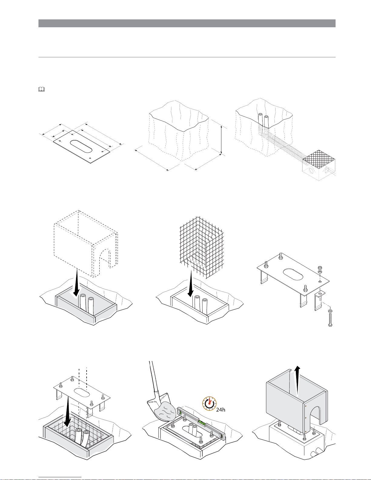
Set up a foundation frame that is larger than the anchoring plate and sink it into the dug hole.
Fit an iron cage into the foundation frame to reinforce the concrete.
Assemble the four anchoring braces to the anchoring plate.
Place the plate over the iron cage.
Fill the foundation frame with concrete. The base must be perfectly level with the bolts which are entirely above surface.
Wait at least 24 hrs for the concrete to solidify.
Remove the foundation frame.
INSTALLING
⚠
The following illustrations are mere examples. Consider that the space available where to fit the barrier and accessories will vary
depending on the area where it is installed. It is up to the installer to find the most suitable solution.
SETTING UP THE ANCHORING PLATE
⚠
If the flooring does not allow for a sturdy fastening of the entry unit, you will have to set up a cement slab.
Dig a hole for the foundation frame.
Set up the corrugated tubes needed for the wiring coming out of the junction pit.
The number of tubes depends on the type of system and the accessories you are going to fit. Set up a 230 V power-supply cable.
Page 10
p. 10 - Manual FA00571-EN v. 1 - 08/2017- © CAME S.p.A. - The contents of this manual may be changed, at any time, and without notice.
Fill the hole with earth around the concrete block.
Remove the nut and washer from the bolts
Fit the electric cables into the tubes so that they come out about 600 mm.
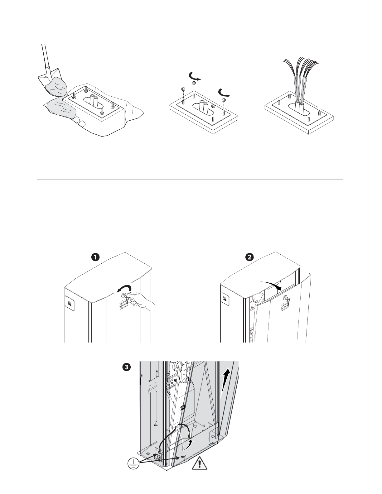
SETTING UP THE BARRIER
⚠
Warning! Use hoisting equipment to transport and position the barrier. The mounting must be done by at least two people. During the
initial mounting and fastening, the barrier may be unstable and could tip over. Then be careful to no rest against it until it is completely
and securely fastened.
Fit the customized key into lock on the inspection hatch and turn it counterclockwise.
Before removing the cabinet hatch, make sure you have disconnected the earthing cable which is connected to the door.
Page 11

180°
90°
M N M N
p. 11 - Manual FA00571-EN v. 1 - 08/2017- © CAME S.p.A. - The contents of this manual may be changed, at any time, and without notice.
⚠
The barrier is set up for installing on the left.
If installing on the right side, invert the opening direction, in the following way:
- release the gearmotor, loosen the screws from the rods ❶;
- remove the transmission lever from the lever arm ❷;
- free up the lever arm from the drive shaft by removing the screws and elastic
dowels ❸;
- turn the lever arm 90° counter clockwise ❹;
- fasten the lever arm to the drive shaft by refitting the screws and dowels ❺;
- remove the mechanical closing stop and fit it into the opposite side ❻;
- remove the opening mechanical stop, turn it 180° and fasten it (locking torque
of 77.5 Nm) ❼;
- refit the transmission lever to the lever arm (locking torque of 77.5 Nm)) ❽;
-lock the gearmotor and turn the screws onto the rods ❾;
- from the control panel, invert gearmotor phase M to N ❿.
LEFT RIGHT
①Brown
②Blue
Page 12

p. 12 - Manual FA00571-EN v. 1 - 08/2017- © CAME S.p.A. - The contents of this manual may be changed, at any time, and without notice.
362 mm
LENGTH OF BOOM
PASSAGE WIDTH CLEARANCE (5000 mm max.)
Fit the boom attachment-cover to the drive shaft plate. Keep the bolts loose.
Fit the boom into the boom attaching cover and fasten it using the screws.
001G0502 Semi-oval section boom made
of white varnished aluminum.
Ø 100 mm, boom length: 5350
mm.
001G05350 Semi-oval section white
varnished aluminum boom,
complete with end-cap.
Ø 100 mm, boom length: 5350
mm.
Calculate the boom length by taking into account the passage width clearance. Cut o any excess.
FASTENING THE BARRIER
Place the cabinet onto the anchoring plate and fasten it using nuts and washers.
Page 13

001G0502
001G05350
A
A
B
B
p. 13 - Manual FA00571-EN v. 1 - 08/2017- © CAME S.p.A. - The contents of this manual may be changed, at any time, and without notice.
PASSAGE WIDTH CLEARANCE (m)
3 ÷ 3.5 3.5 ÷ 4 4 ÷ 4.5 4.5 ÷ 5
Boom AABB
Boom with swing-leg 001G02808 A B B A + B
Boom with luminous cord 001G28401 A B B A + B
Boom with 001G02808 swing rest and 001G28401 luminous cord B B A + B A + B
Boom with skirt 001G0465 A B A + B A + B
Boom with 001G0465 skirt and 001G028401 luminous cord B B A + B A + B
The boom includes the transparent groove cover and end cap.
⚠
WARNINGS!
001G02802 Cannot be used on barriers fitted with the 001G0465 skirt or 001G02808 swing rest
001G02807 MUST be used with passage widths exceeding 3 m.
001G0465 - 001G02808 Cannot be used together.
PASSAGE WIDTH CLEARANCE (m)
3 ÷ 4 4 ÷ 5
Boom AB
oom with 001G0465 skirt or 001G028401 swing-rest B A + B
Passage width clearance ( 5 m max.)
Passage width clearance ( 5 m max.)
BALANCING THE BOOM
The barrier is supplied with two Ø 50 mm springs (001G04060). The springs are fitted to the level arm (in holes B).
Depending on the final configuration of the barrier, you may have to exclude one of the springs or change the fastening position (see the
tables below).
⚠
When configuring the barrier, make sure the gearmotor is locked!
Page 14

45°
45°
p. 14 - Manual FA00571-EN v. 1 - 08/2017- © CAME S.p.A. - The contents of this manual may be changed, at any time, and without notice.
Release the gearmotor and loosen the rod nut.
Manually turn the spring to increase or reduce the traction. The boom should stabilize at 45°.
Fit the nut to fasten the rod to the spring and tighten it.
Lock the gearmotor once again.
Check the proper working state of the spring.
With the boom raised vertically the spring is not taut.
With the boom lowered horizontally the spring is taut.
Warning! After performing balancing procedures, LUBRICATE THE SPRINGS WITH SPRAY GREASE!
Page 15

26V
0V
230
0
Rosso
Bianco
Blu
Arancione
p. 15 - Manual FA00571-EN v. 1 - 08/2017- © CAME S.p.A. - The contents of this manual may be changed, at any time, and without notice.
CONTROL PANEL
⚠
Warning! Before working on the control panel, cut off the main power supply and, if present, remove any batteries.
Power supply to the control panel and control devices: 24 V AC/DC.
Functions on input and output contacts and time and user management details, are set up and viewable on the control panel's display.
All wiring connections are quick-fuse protected.
FUSE TABLE ZL39
- Line
3.15 A-F = 120 V
1.6 A-F = 230 V
- Card 1 A-F
- Accessories 2 A-F
DESCRIPTION OF PARTS
1. Transformer
2. Overheating protection terminals
3. Transformer terminals
4. Ferrite
5. Accessories fuse
6. Display
7. EMC01 filter
8. Terminals for transponder devices
9. Keypad selector terminal
10. Terminals for paired / alternate / CRP connections
11. Terminals for control and safety devices
12. Antenna terminal
13. AF card connector
14. RSE board connector
15. Connector for the R700 / R800 card
16. Programming buttons
17. Memory roll board connector
18. Programming warning LED
19. Power supply on warning LED
20. Control-board fuse
21. Line fuse
22. Power supply terminals
23. Terminals for gearmotor
24. Terminals for encoder
Page 16

L N L1T L2T M N + E -
p. 16 - Manual FA00571-EN v. 1 - 08/2017- © CAME S.p.A. - The contents of this manual may be changed, at any time, and without notice.
ELECTRICAL CONNECTIONS
Connect all wires and cables in compliance with the law while using suitable cable glands, as shown in the drawing.
⚠
Use a cable gland only for the 230 V AC power supply cable.
⚠
The electrical cables must not touch any heated parts such as the motor, transformer, and so on.
24 V DC gearmotor with encoder
Brown
Blue
FACTORY WIRING
The gearmotor is already connected.
To install the barrier on the right, follow the instructions in the PREPARING THE BARRIER.
Ferrite
White
Brown
Green
Page 17

A B GND A B S1 GND
10 11
- +
CAME
10 11 E1 E6 Rx Tx 1 2 3 3P 4 5 7 CX CY
p. 17 - Manual FA00571-EN v. 1 - 08/2017- © CAME S.p.A. - The contents of this manual may be changed, at any time, and without notice.
POWER SUPPLY
230 V AC - 50/60 Hz
Output to power 24 V AC accessories (normally) - max. 40 W.
If the power is out, you can power up the 24 V DC accessories by
using buffer batteries.
Output to notify the state of the barrier (Contact rated for: 24 V AC - 3 W max.).
It flags the state of the barrier, see function F10.
Output for connecting the luminous cord (Contact rated for: 24 V AC - 32 W
max.).
It flags the state of the barrier, with intermittent lights, see function F15.
Additional light connection output (Contact rated for: 24 V AC - 25 W max):
- flashing light, that flashes when the barrier is opening and closing.
- cycle or courtesy light, which is a freely positionable outdoor light for
enhanced lighting in the driveway.
Cycle, stays on from the moment in which the barrier starts opening until it
closes completely (including the automatic closing time).
Courtesy, stays on a settable time of between 60 and 1180 seconds, see
function F18.
SIGNALING DEVICES
EMC01
FILTER
Page 18

AF
R700
R800
10 11 E1 E6 Rx Tx 1 2 3 3P 4 5 7 CX CY
GND A B S1 GND
p. 18 - Manual FA00571-EN v. 1 - 08/2017- © CAME S.p.A. - The contents of this manual may be changed, at any time, and without notice.
CONTROL DEVICES
Antenna with RG58 cable
OPEN-CLOSE-INVERT function (step-step) from control
device (NO contact).
ONLY CLOSE function from control device (NO contact).
Warning: in MAINTAINED ACTION mode, the control
device must be connected to 2-4.
Warning! OPEN ONLY function from control device
with NO contact. Connect only to paired or alternate
installations. (see chapter called PAIRED FUNCTION or
ALTERNATE FUNCTION)
OPEN ONLY function from control device with NO
contact.
Warning: in MAINTAINED ACTION mode, the control
device must be connected to 2-3.
STOP button (NC contact). For stopping the boom while
excluding the automatic closing. To resume movement
either press the control button or any other control
device.
If unused, select 0 (Deactivated) from Function F1.
Keypad selector
Transponder or card reader
Fit the R700 decoding card for
recognition of the TSP00 sensor or the
LT001 card reader.
Fit the R800 decoding card so
that the keypad selector can be
recognized.
WARNING! Before fitting any plug-in card, such as the AF or R800 one, YOU MUST CUT OFF THE MAINS POWER SUPPLY and, if
present, disconnect any batteries.
Fit the AF radio-frequency card to control the barrier
via a transmitter.
Black
Red
Blue
White
Page 19

RX TX
./ # .#
RX TX
DELTA-S
DELTA
DIR
10 11 E1 E6 Rx Tx 1 2 3 3P 4 5 7 CX CY 10 11 E1 E6 Rx Tx 1 2 3 3P 4 5 7 CX CY
10 11 E1 E6 Rx Tx 1 2 3 3P 4 5 7 CX CY
RX TX
./ # .#
RX TX
DIR / DELTA-S
DELTA
10 11 E1 E6 Rx Tx 1 2 3 3P 4 5 7 CX CY
p. 19 - Manual FA00571-EN v. 1 - 08/2017- © CAME S.p.A. - The contents of this manual may be changed, at any time, and without notice.
SAFETY DEVICES
Photocells
Configure contact CX or CY (NC), safety input for photocells.
See function ofInput CX (function F2) or CY (function F3) in:
C1 reopening while closing. When the barrier is closing, opening the contact causes its movement to invert until fully opened;
C4 obstruction wait. Theleaf stops if moving and starts moving again once the obstruction is removed;
C5 immediate closing. Closing the barrier after a vehicle has passed through the operating area of the safety devices; C9 immediate
closing with obstruction wait when closing. Closing the barrier after a vehicle has passed through the operating area of the safety
devices;
C9 immediate closing with obstruction wait when closing. Closing the boom after a vehicle has passed through the operating area of
the safety devices.
If unused, contacts CX and CY should be deactivated during programming.
Photocells (safety test)
At each opening and closing command, the control board checks the efficacy of the safety devices (such as, photocells).
Any malfunction inhibits any command and the display will show the Er4 wording.
Enable function F5 in programming.
Page 20

A B GND
A B GND
UTP CAT 5
1 2 3 4
1
2
3
4
RSE
RX TX
./
#.#
RX TX
DIR / DELTA-S
DELTA
10 11 E1 E6 Rx Tx 1 2 3 3P 4 5 7 CX CY 10 11 E1 E6 Rx Tx 1 2 3 3P 4 5 7 CX CY
p. 20 - Manual FA00571-EN v. 1 - 08/2017- © CAME S.p.A. - The contents of this manual may be changed, at any time, and without notice.
CONNECTION FOR PAIRED OR ALTERNATE OPERATION OR FOR CAME REMOTE PROTOCOL (CRP)
Fit the RSE card.
Photocells (sleep mode)
The Sleep Mode function cuts down on energy consumption when in stand-by.
Select 1 from function F 60.
Page 21

~1°
p. 21 - Manual FA00571-EN v. 1 - 08/2017- © CAME S.p.A. - The contents of this manual may be changed, at any time, and without notice.
ESTABLISHING THE LIMIT-SWITCH POINTS
Close the inspection hatch and power up the system. Move the boom the check that it is parallel to the road surface when closed and
at about 89° when open.
⚠
The barrier's opening and closing maneuvers must be performed with the inspection hatch closed.
To correct the boom's vertical position:
- lower the boom;
- open the inspection hatch;
- turn the jointed arm clockwise or counter-clockwise to increase or decrease the boom travel .
Fasten the boom using the counter nuts , above and below .
To correct the horizontal position:
- raise the boom;
- turn the mechanical limit-switch stop clockwise to increase the boom travel or counter clockwise to decrease it .
Fasten the stop using the screw .
Mechanical stop
UNI 5739 6X20 bolt
Page 22

S1 GND
{
{
{
888 888888
10”
1”
p. 22 - Manual FA00571-EN v. 1 - 08/2017- © CAME S.p.A. - The contents of this manual may be changed, at any time, and without notice.
Display
The ESC button is for:
- exiting menus;
- cancelling changes.
The < > keys are for:
- moving from one item to another;
- increasing or decreasing values.
The ENTER key is for:
- entering menus;
- confirming or memorizing set values.
PROGRAMMING
DESCRIPTION OF THE PROGRAMMING COMMANDS
To enter the menu, keep the ENTER button pressed
for at least one second.
To exit the menu, wait 10 seconds or press ESC.
FUNCTIONS MENU
⚠
When programming, the operator needs to be in stop mode.
F1 Total stop [1-2]
NC input - Barrier stops while excluding any automatic closing; to resume movement, use the
control device. Fit the safety device onto (1-2), if unused, select 0.
0= Deactivated (default) / 1= Activated
F2 Input [2-CX]
NC Input - For associating: C1 = reopening during closing for photocells, C4 = obstruction wait, C5
= immediate closing, C9 = immediate closing with obstruction wait when closing.
0= Deactivated (default) / 1=C1 / 4=C4 / 5=C5 / 9=C9
F3 Input [2-CY]
NC Input - For associating: C1 = reopening during closing for photocells, C4 = obstruction wait, C5
= immediate closing, C9 = immediate closing with obstruction wait when closing.
0= Deactivated (default) / 1=C1 / 4=C4 / 5=C5 / 9=C9
F5 Safety test
After every opening or closing command, the board will check whether the photocells are working
properly.
0= Deactivated (default) / 1=CX / 2=CY / 4=CX+CY
F6 Maintained action
The barrier opens and closes by keeping a button pressed. Opening button on contact 2-3 and
closing button on contact 2-4. All other control devices, even radio-based ones, are excluded.
0= Deactivated (default) / 1= Activated
Page 23

p. 23 - Manual FA00571-EN v. 1 - 08/2017- © CAME S.p.A. - The contents of this manual may be changed, at any time, and without notice.
F9
Obstruction detection
with motor stopped
With the barrier closed, open, or after a total stop, the gearmotor stays idle if the safety devices,
that is, the photocells, detect an obstruction.
0 = Deactivated (default) / 1 = Activated
F10
State of barrier
notifi cation output
It signals the barrier's state The signal device is connected to contact 10-5.
0 = on with boom raised and moving (default) / 1 = it fl ashes intermittently each half second when
the boom is opening, and fl ashes intermittently each second when the boom is closing, and stays
on when the boom is raised, and stays o when the boom is lowered.
F11 Encoder
Managing slow-downs, obstruction detections and sensitivity.
0 = Activated (default) / 1 = Deactivated
F14 Sensor type
Setting the type of accessory for controlling the operator.
0 = command with transponder sensor or magnetic card reader / 1 = command with keypad
selector (default)
F15 Luminous cord
It signals the state of the barrier by using intermittent lights. Luminous cord connected onto 10-E6.
0 = Boom is moving (default) / 1 = Boom is moving and lowered.
F18 Additional light
Output for connecting the additional light onto 10-E1:
- fl ashing light, which fl ashes when the barrier is opening and closing;
- cycle, stays on from the moment the barrier starts opening until it is fully closed, including the
waiting time before the automatic closing.
- courtesy, stays on for a settable time of between 60 and 180 seconds. To set the time, see
function F25.
0 = Flashing light (default) / 1 = Cycle / 2 = Courtesy
F19
Automatic Closing
Time
The automatic-closing wait starts when the opening limit switch point is reached and can be set to
between 1 and 180 seconds. The automatic closing does not activate if any of the safety devices
trigger when an obstruction is detected, or after a total stop, or during a power outage.
0 = Deactivated (default) / 1 = 1 second /... / 180 = 180 seconds
F21 Pre-fl ashing time
Adjusting the pre-fl ashing time of the fl ashing light connected to 10-E1 before each maneuver. The
fl ashing time is adjustable from one to ten seconds.
0 = Deactivated (default) / 1 = 1 second /... / 10 = 10 seconds
F22 Operating time
Motor's operating time, when opening and closing. It can be set to between 5 and 120 seconds.
5 = 5 seconds /... / 120 = 120 seconds (default)
F25 Courtesy light time
Additional light (courtesy), stays lit for the necessary time while the barrier is opening and closing.
It can be set to between 60 and 180 seconds.
60 = 60 seconds /... / 180 = 180 seconds (default)
F28
Speed of opening
maneuver
Setting the barrier's opening speed, calculated as a percentage.
Warning!The speed parameter fi elds vary depending on the type of boom:
- for booms of 2 m to 4 m with jointed boom, set the speed percentage to between 70 and 100;
- for booms of 6 m and 8 m, set the speed percentage to between 80 and 100.
70 = 70% of the maximum speed /… / 100 = 100% of the maximum speed
F29
Speed of closing
maneuver
Setting the barrier's closing speed, calculated as a percentage.
Warning!The speed parameter fi elds vary depending on the type of boom:
- for jointed booms of 2 m to 4 m, set the speed percentage to between 70 and 100;
- for booms of 6 m and 8 m, set the speed percentage to between 80 and 100.
70 = 70% of the maximum speed /… / 100 = 100% of the maximum speed
F30
Opening slow-down
speed
Setting the barrier's opening slow-down speed, calculated as a percentage.
Warning!The speed parameter fi elds vary depending on the type of boom:
- for jointed booms of 2 m, set the slow-down speed percentage to between 20 and 40;
- for booms of 4 m, set the slow-down speed percentage to between 20 and 35.
- for booms of 6 m and 8 m, set the slow-down speed percentage to between 15 and 40.
15 = 15% of the maximum speed /… / 40= 40% of the maximum speed
Page 24

p. 24 - Manual FA00571-EN v. 1 - 08/2017- © CAME S.p.A. - The contents of this manual may be changed, at any time, and without notice.
F31
Closing slow-down
speed
Setting the barrier's closing slow-down speed, calculated, calculated as a percentage.
Warning! The speed parameter fi elds vary depending on the type of boom:
- for jointed booms of 2 m, set the slow-down speed percentage to between 20 and 40;
- for booms of 4 m, set the slow-down speed percentage to between 20 and 25.
- for booms of 6 m and 8 m, set the slow-down speed percentage to between 15 and 20.
15 = 15% of the maximum speed /… / 40= 40% of the maximum speed
F33 Calibration speed
Setting the boom's travel automatic calibration, calculated as a percentage.
20 = 20% of the maximum speed /… / 40= 40% of the maximum speed (default)
F34 Travel sensitivity
Adjusting obstruction detection sensitivity during gate travel.
10 = Maximum sensitivity /… / 100= Minimum sensitivity (default)
F35
Slow-down
sensitivity
Adjusting obstruction detection sensitivity during slow-down.
10 = Maximum sensitivity /… / 100= Minimum sensitivity (default)
F37
Opening slow-down
point
Percentage adjustment of the boom's total travel, from the beginning of the opening slow-down
point.
Warning! The percentage varies depending on the boom type:
- for jointed 2 m and 4 m booms, set the percentage to between 40 and 60;
- for 6 m and 8 m booms, set the percentage to between 60 and 70.
40 = 40% of the total travel /… / 60 = 60% of the total travel
F38
Closing slow-down
point
Percentage adjustment of the boom's total travel, from the beginning of the opening slow-down
point.
Warning! The percentage varies depending on the boom type:
- for jointed, 2 m booms, set the speed percentage to between 20 and 40;
- for 4 m booms, set the percentage to between 50 and 60;
- for 6 m booms, set the percentage to between 60 and 70;
- for 8 m booms, set the percentage to between 65 and 75;
20 = 20% of the total travel /… / 75 = 75% of the total travel
F40
Closing approach
point
Adjusting, as a percentage of the boom's total travel, the closing approach starting point.
This function only appears if the Encoder function is activated.
1 = 1% of the total travel /… / 20 = 20% of the total travel
F49
Managing the serial
connection
To enable operation in paired, alternate or CRP (Came Remote Protocol) modes.
0 = Deactivated (default) / 1 = Paired / 2 = Alternate / 3 = CRP
F50 Saving data
Saving memorized users and settings in the memory roll.
This feature only appears if a memory roll has been fi tted into the control board.
0 = Deactivated (default) / 1 = Activated
F51 Reading of data
Uploading data saved in memory roll.
This feature only appears if a memory roll has been fi tted into the control board.
0 = Deactivated (default) / 1 = Activated
F52
Transferring
parameters in
paired/alternate
mode
Uploading settings from Master to Slave.
This only appears if the F49 function is set to PAIRED or ALTERNATE.
0 = Deactivated (default) / 1 = Activated
F56 Peripheral number
To set the peripheral number from 1 to 255 for each control board when a system is fi tted with
several operators and features the CRP (Came Remote Protocol) connection system.
1 ----> 255
F60 Sleep mode
For reducing energy consumption by the stand-by photocells.
0 = Deactivated (default) / 1 = Activated
F61 Pre-fl ashing
After an opening or closing command, the fl ashing light connected to 10-E1m fl ashes before
starting the maneuver.
For setting the time, see function F 21.
0 = when opening and closing (default) / 1 = only when closing / 2 = only when opening
Page 25

p. 25 - Manual FA00571-EN v. 1 - 08/2017- © CAME S.p.A. - The contents of this manual may be changed, at any time, and without notice.
F63 COM speed
For setting the communication speed used in the CRP (Came Remote Protocol) connection system.
0 = 1200 Baud / 1 = 2400 Baud / 2 = 4800 Baud / 3 = 9600 Baud / 4 = 14400 Baud / 5 = 19200
Baud / 6 = 38400 Baud (default) / 7 = 57600 Baud / 8 = 115200 Baud
U1 Entering users
Entering up to 250 users and associating to each one a function of choice among those included.
Use a transmitter or other control device to enter the data (see paragraph called ENTERING A USER
WITH AN ASSOCIATED COMMAND).
1 = Step-step command (open-close) / 3 = Open only command / 4 = Partial opening/pedestrian
command (only for paired or alternate mode systems)
U2 Deleting users Deleting single users (see paragraph called DELETING SINGLE USERS)
U3 Deleting users
Deleting all users.
0 = Deactivated (default) / 1 = Delete
A1 Boom type
To establish the boom type.
Warning! The choice of boom type limits certain speed, slow-down and calibration limits. This is to
ensure proper operation of the barrier.
0 = do not use /2 = do not use /4 = 4 6 = 6 8 = do not use
A2 Motor test Test to check the right direction of travel of the boom (see paragraph called MOTOR TEST).
A3 Travel calibration
Automatic calibration of the boom travel (see paragraph called TRAVEL CALIBRATION).
This function appears only is the Encoder function is activated.
A4
Resetting
parameters
Attention! The default settings will be restored.
0= Deactivated (default) / 1= Activated
A5 Maneuver count
For viewing the number of maneuvers done by the boom (1 = 1,000 maneuvers; 100 = 100,000
maneuvers; 999 = 999,000 maneuvers)
A7
Duration of boom
slow-down during
closing
This sets the duration of the boom's slow down between the maneuvering and slow-down speeds
when closing (see fi gure A).
This function appears only if the Encoder function is activated.
1 = Minimum / 2 = Medium ( default ) / 3= Maximum
H1 Version View the fi rmware version.
Maximum duration
of deceleration
Average duration
of deceleration
(default)
Minimum
duration of
deceleration
Page 26

ESC < > ENTER
I
ESC < > ENTER
2
a
ESC < > ENTER
---
ESC < > ENTER
oP I
ESC < > ENTER
a3
ESC < > ENTER
i
ESC < > ENTER
cl i
ESC < > ENTER
op I
p. 26 - Manual FA00571-EN v. 1 - 08/2017- © CAME S.p.A. - The contents of this manual may be changed, at any time, and without notice.
TRAVEL CALIBRATION
⚠
During the calibration, all safety devices will be disabled except for the PARTIAL STOP one.
❶ Select A3 and press ENTER to confirm.
❷ Select 1 and press ENTER to confirm the travel calibration operation.
❸ The operator will perform a closing maneuver until the limit-switch point ...
❹ then, the barrier will perform an opening maneuver until the endstop point.
SETTING UP
Once the connections are all set, have skilled, qualified staff commission the barrier into service.
Before continuing, make sure that the way is clear from any obstruction.
Power up and begin configuring the system. Important! Start programming by first doing the following functions:
- type of boom (see function A1);
- motor test (see paragraph called MOTOR TEST);
- total stop (see function F1);
- calibrating travel (see paragraph called CALIBRATING TRAVEL).
MOTOR TEST
❶ Select A2. Press ENTER to confirm
❷ Select 1 to activate the test. Press ENTER to confirm ...
❸... the following characters will appear (----), while standing by for a command.
❹ Keep pressed the button with the arrow < and check whether the operator performs an opening maneuver.
If the operator performs a closing maneuver, invert the motor's phases (M with N).
When the programming is done, check that the barrier and all devices connected to it are operating properly. Use the (<, >) programming
buttons to open and close the barrier and the ESC button to stop it.
⚠
After powering up the system, the first maneuver is always the opening. In this phase, the barrier will not close, you need to wait for
a complete opening maneuver.
⚠
Immediately press the STOP button if the system manifests any anomalies, malfunctions, noises, strange vibrations or unexpected
behavior.
Page 27

ESC < > ENTER
2
2
ESC < > ENTER
2
U
ESC < > ENTER
C
L
ESC < > ENTER
I
ESC < > ENTER
I
U
ESC < > ENTER
8
1
2
3
4
5
6
7
8
9
10
11
12
13
14
15
16
17
18
19
20
21
22
23
24
25
1
234
5
6
789
1
0
11
1
2
1
3
1
4
1
5
1
6
1
8
2
0
2
122
2
3
2
4
2
5
p. 27 - Manual FA00571-EN v. 1 - 08/2017- © CAME S.p.A. - The contents of this manual may be changed, at any time, and without notice.
DELETING SINGLE USERS
❶ Select U2 and press ENTER to confirm.
❷ Use the arrow keys select the number of the user you wish to delete. Press ENTER to confirm ...
❸ ... Clr will appear on the screen to confirm deletion.
MANAGING USERS
When adding/deleting users, the flashing numbers that appear, are numbers that can be used for other users you may wish to add
(maximum 25 users).
Before registering the users, make sure the AF radio-frequency card is fitted into the connector (see paragraph called CONTROL
DEVICES).
ENTERING A USER WITH AN ASSOCIATED COMMAND
❶ Select U1. Press ENTER to confirm.
❷ Select a command to associate to the user: The commands are:
- step-step (open-close) = 1;
- open = 3;
- partial opening/pedestrian = 4.
The partial/pedestrian opening command only appears if the F49 function is activated.
Press ENTER to confirm...
❸
.... a number between 1 and 25 will flash for some seconds. Send the code from the transmitter or other control device such as a
sensor, card reader or keypad selector.
If you want to add another command on the same transmitter, repeat the procedure and associated it on another button.
LIST OF REGISTERED USERS
Note down all registered users in the table below.
Page 28

ESC < > ENTER
0
F
5
ESC < > ENTER
I
F
5
p. 28 - Manual FA00571-EN v. 1 - 08/2017- © CAME S.p.A. - The contents of this manual may be changed, at any time, and without notice.
SAVING AND UPLOADING ALL DATA (USERS AND CONFIGURATION) WITH THE MEMORY ROLL
Procedure for memorizing all of the system's user and configuration data by using the Memory Roll, so they can be used with another
control board, even on another system.
Warning! Fitting and extracting the Memory Roll must be done with the mains power disconnected.
❶ Fit the Memory Roll into the its corresponding connector on the control board.
❷ Select F50 and press ENTER to confirm the saving of data in the Memory Roll.
❸ Extract the Memory roll and fit it into the connector of another control board.
❹Select F51 and press ENTER to confirm the uploading of data into the Memory Roll.
After memorizing the data, it is best to remove the Memory roll.
Memory roll
FINAL OPERATIONS
Once the barrier is commissioned, check that there are no obstructions to the mechanical moving parts.
Before replacing and closing the inspection hatch, reconnect the earthing cable.
Memory roll
Page 29

p. 29 - Manual FA00571-EN v. 1 - 08/2017- © CAME S.p.A. - The contents of this manual may be changed, at any time, and without notice.
TROUBLESHOOTING
PROBLEM REFERENCE CHECK
The barrier neither opens nor closes 1-2-3-4-6-8-
13-18
1 - Lock the inspection hatch with the key
The barrier opens but does not close 4-7 2 - Deactivate the MAINTAINED ACTION function
The barrier closes but does not open 4-7-12-13 3 - Check the power supply and fuses
The barrier does not automatically close 11-12-13 4 - The NC contacts are open
The barrier does not work with the transmitter 2-14-16 6 - Deactivate the MASTER-SLAVE function
The boom's direction of travel is inverted 7-18 7 - Check the boom's balancing and spring tautness
Only one transmitter works 22 8 - Deactivate the OBSTRUCTION DETECTION function
The photocells do not work 12-23-24 11 - Activate the AUTOMATIC CLOSING function
The warning LED flashes quickly 4 12 - Check the proper direction of travel
The warning LED stays lit 13 13 - Check the control devices
The boom does not reach the limit-switch 7 14 - Replace the AF card
The boom cannot be balanced 7-15 15 - Check the length ration between boom and applied
accessories
The barrier does not slow down 7-15 16 - Memorize the radio code again
The barrier does not work with emergency
batteries
8-25-26 18 - Adjust the sensitivity
The boom starts slow 7 22 - Enter or duplicate the same code on all transmitters
23 - Activate the photocells
24 - Connect the photocells serially instead of in parallel fashion
25 - Check the batteries
26 - Respect the photocell's input voltage polarities
ERROR MESSAGE
The error messages appear on display or are notified by the LEDs.
Er1 The boom travel calibration was interrupted by the activation of the STOP button.
Er3 Encoder is broken.
Er4 Services test error.
Er5 Insufficient working time.
Er6 Maximum number of obstructions detected.
Er7 Transformer overheated / inspection hatch open / boom detached from gearmotor.
Er8 Encoder excluded.
C0 Contact 1-2 (NC) is open.
C1, C4, C5 or C9 The (NC) contacts are open.
The warning LED
flashes
The control board is not yet calibrated for the boom travel.
Page 30

SLAVE
MASTER
SLAVE
MASTER
SLAVE
MASTER
SLAVE
MASTER
SLAVE
MASTER
MASTER
SLAVE
p. 30 - Manual FA00571-EN v. 1 - 08/2017- © CAME S.p.A. - The contents of this manual may be changed, at any time, and without notice.
Send the PARTIAL/PEDESTRIAN OPENING command
(contact 2-3P) from a transmitter or other control
device, to open the boom on the SLAVE barrier. .
Approach the MASTER barrier, which will automatically
open only after the SLAVE barrier automatically closes
.
Send the STEP-STEP (contact 2-7) command from a
transmitter or other control device, to simultaneously
open the booms of the MASTER and SLAVE barrier.
Send the ONLY OPEN command (contact 2-3) from a
transmitter or other control device, to open the boom
of the MASTER barrier..
Approach the SLAVE barrier. It will automatically open
only after the MASTER barrier automatically closes. .
ALTERNATE FUNCTION
Important! Start by doing the following on both barriers:
- Fit the RSE card into the connector on the control panel of both operators.
- connect the two control panels via a CAT 5 type-cable (max 1,000 m) to terminals A-A / B-B / GND-GND, see paragraph on CONNECTING
FOR PAIRED OR ALTERNATE OPERATING MODE.
Connect the safety and control device with ONLY OPEN function (contact 2-3) and STEP-STEP function (contact 2-7) on the MASTER control
panel.
Connect the safety and control devices with PARTIAL / PEDESTRIAN OPENING function (contact 2-3P) only on the SLAVE control panel.
Important! Activate function F 19 (automatic closing time) on the control panel of both operators.
Memorizing
Perform the enter-user procedure with the ONLY OPEN, and STEP-STEP command on the MASTER control panel while the
PARTIAL / PEDESTRIAN OPENING function is to be performed on the SLAVE control board.
Confi guring the MASTER operator
Select function F 49. Press ENTER to confi rm.
Select 2 (alternate) and press ENTER.
Transferring parameters from MASTER to SLAVE
Select function F 52 on the MASTER control panel.
Select 1 and press ENTER.
Programming
On both barriers, set the following functions:
- setting the boom type (A1);
- motor test (A2)
- total stop (F1);
- travel calibration (A3).
Carry out any settings and adjustments on the MASTER control panel.
Operating modes
ONLY OPEN (contact 2-3) command. For opening MASTER barrier boom.
PARTIAL/PEDESTRIAN OPENING (contact 2-3P) command. For opening the SLAVE barrier boom.
STEP-STEP (contact 2-7) command. Both booms open. This is an emergency opening command, to free the passage.
For the types of command that can be selected and paired to users, see the ENTERING USERS WITH ASSOCIATED COMMANDS
Page 31

MASTER
SLAVE
MASTER
SLAVE
MASTER
SLAVE
p. 31 - Manual FA00571-EN v. 1 - 08/2017- © CAME S.p.A. - The contents of this manual may be changed, at any time, and without notice.
PAIRED OPERATION
Important! Start by doing the following on both barriers:
- Fit the RSE card into the connector on the control panel of both operators.
- connect the two control panels via a CAT 5 type-cable (max 1,000 m) to terminals A-A / B-B / GND-GND, see paragraph on CON-
NECTING FOR PAIRED OR ALTERNATE OPERATING MODE.
- connect all of the control and safety devices to the MASTER control panel.
Important! Deactivate function F 19 (automatic closing time) on the SLAVE barrier's control panel.
Memorizing
Run the user entering procedure with the OPEN ONLY and PEDESTRIAN / PARTIAL OPENING command on the MASTER panel.
Confi guring the MASTER operator
Select function F 49. Press ENTER to confi rm.
Select 1 (paired) and press ENTER.
Transferring parameters from MASTER to SLAVE
Select function F 52 on the MASTER control panel.
Select 1 and press ENTER.
Programming
On both barriers, set the following functions:
- setting the boom type (A1);
- the motor test (A2);
- total stop (F1);
- travel calibration (A3).
Carry out any settings and adjustments on the MASTER control panel.
Operating modes
STEP-STEP or OPEN ONLY command. Both booms open.
PARTIAL OPENING/PEDESTRIAN command. Only the MASTER barrier opens.
For the types of command that can be selected and paired to users, see the ENTERING USERS WITH ASSOCIATED COMMANDS.
Page 32

CAME S.p.A.
Via Martiri Della Libertà, 15
31030 Dosson di Casier - Treviso - Italy
tel. (+39) 0422 4940 - fax. (+39) 0422 4941
p. 32 - Manual FA00571-EN v. 1 - 08/2017- © CAME S.p.A. - The contents of this manual may be changed, at any time, and without notice.
DISMANTLING AND DISPOSAL
☞
CAME CANCELLI AUTOMATICI S.p.A. applies a certified Environmental Management System at its premises, which is compliant
with the UNI EN ISO 14001 standard to ensure the environment is safeguarded.
Please continue safeguarding the environment. At CAME we consider it one of the fundamentals of our operating and market
strategies. Simply follow these brief disposal guidelines:
DISPOSING OF THE PACKAGING
The packaging materials (cardboard, plastic, and so on) should be disposed of as solid household waste, and simply separated from
other waste for recycling.
Always make sure you comply with local laws before dismantling and disposing of the product.
DISPOSE OF RESPONSIBLY!
DISMANTLING AND DISPOSAL
Our products are made of various materials. Most of these (aluminum, plastic, iron, electrical cables) are classified as solid
household waste. They can be recycled by separating them before dumping at authorized city plants.
Whereas other components (control boards, batteries, transmitters, and so on) may contain hazardous pollutants.
These must therefore be disposed of by authorized, certified professional services.
Before disposing, it is always advisable to check with the specific laws that apply in your area.
DISPOSE OF RESPONSIBLY!
 Loading...