

CAME G4140ZU, G4140IZU Installation Manual
GARD4 SERIES
INSTALLATION MANUAL
G4140ZU - G4140IZU
AUTOMATION FOR STREET BARRIERS

Pag. 2 - Manual code: 119G V2 9 ver. 2.0 09/2010 © CAME cancelli automatici s.p.a. - The data and information reported in this installation manual are susceptible to change at any time and without obligation on CAM E cancelli automatici s.p.a. to notify users.
It is extremely important that all parties involved in the installation and operation of the road barrier system read and understand the
following warning instructions.
WARNING – To reduce the risk of injury or death:
1. READ AND FOLLOW ALL INSTRUCTIONS.
2. Never let children operate or play with gate controls. Keep the remote control away from children.
3. Always keep people and objects away from the gate. NO ONE SHOULD CROSS THE PATH OF THE
MOVING GATE.
4. Test the road barrier monthly. The gate MUST reverse on contact with a rigid object or stop when an object activates the
non-contact sensors. After adjusting the force or the limit of travel, re-test the road barrier. Failure to adjust and re-test the
road barrier properly can increase the risk of injury or death.
5. Use the emergency release only when the road barrier is not moving.
6. KEEP THE BARRIER PROPERLY MAINTAINED. Read the installation manual and have a qualified service
person make repairs
to the road barrier hardware.
7. The entrance is for vehicles only. Pedestrians must use separate entrance.
8. SAVE THESE INSTRUCTIONS.
3. A qualified professional installer should install the road barrier system, its accessories by following these minimum procedures:
a. Power should be disconnected before installing or servicing a road barrier
b. All electrical wiring should comply with all local building and electrical codes
c. All entrapment zones should be covered
d. All installation operating and safety manuals should be left with the owner
INSTRUCTIONS REGARDING INTENDED INSTALLATION OF THE ROAD BARRIER.
1. The road barrier is intended for installation only on traffic roads used for vehicles. Pedestrians must
be supplied with a separate access opening.
2. The road barrier must be properly installed and work freely in both directions prior to the installation of theroad barrier.
Do not over-tighten the road barrier or pressure relief valve to compensate for a damaged road barrier.
IMPORTANT UL-325 SAFETY INSTRUCTIONS
G4140ZU / G4140IZU

Pag. 3 - Manual code: 119G V2 9 ver. 2.0 09/2010 © CAME cancelli automatici s.p.a. - The data and information reported in this installation manual are susceptible to change at any time and without obligation on CAM E cancelli automatici s.p.a. to notify users.
CAME AMERICAS AUTOMATION, LLC
MANUFACTURER’S LIMITED 3-YEAR WARRANTY
Verification of the warranty period requires copies of receipts or other proof of purchase.
Warranty cannot be honored without proof of purchase. Please retain these records.
Came Americas Automation, LLC (“CAME®”) products are warranted by CAME® against defects in materials and manufacturer
workmanship for a period of thirty-six (36) months from the date of purchase, provided the recommended installation manual and
procedure have been followed. CAME®’s sole obligation under this warranty is limited to repairing or replacing, at our option, any
parts which shall be determined by CAME® to be defective, and is conditioned upon CAME® receiving notice of any such defect
within the warranty period. Claims under this warranty may only be made by a purchaser of CAME® products (the “Customer”).
CAME® reserves the right to make the final determination as to whether there is a defect in the materials and/or workmanship,
and whether or not a product is within the warranty period. CAME® is not responsible for any damages or other costs caused by,
or which may result from installation, handling, non-recommended operation, product abuse, or modifications not authorized by
CAME® or for any damages which may arise out of the use of CAME® products.
CAME® sells its products through authorized distributors. This warranty on CAME® products is NOT VALID if the products have
been purchased from an unauthorized distributor, reseller, online E-tailer ( e.g., E-bay®), or if a product serial number has been
altered, removed, or replaced in any way. To verify that you are buying from an authorized CAME distributor or reseller please
call +1 305-433-3307.
In the case of product failure due to defective material or manufacturer workmanship within the thirty-six (36) months warranty
period, the product will be repaired or replaced (at the manufacturer’s option) at no charge to the Customer, if returned, freight
prepaid, to CAME AMERICAS AUTOMATION, LLC, 11345 NW 122nd Street Medley, Florida 33178.
IMPORTANT: Obtain a Return Goods Authorization (RGA) number before returning item(s) to our facilities by submitting a warranty
claim and request for RGA with our customer service department. Products shipped without an RGA number will not be accepted.
Replacements or repaired parts are covered by this warranty for the remainder of the thirty-six (36) month warranty for the original
product or six (6) months from the date of repair or replacement, whichever is greater. CAME® will pay shipping costs at the
ground transport rate for the return to owner of item(s) repaired under warranty.
The manufacturer will not be responsible for any charges or damages incurred in the removal of the defective parts for repair,
or the reinstallation of these parts after repair. Use of any (00021996.doc V.2) components that are not CAME® specified (e.g.
batteries, light bulbs, drive belts, chains or transformers) will void the warranty. This warranty shall be void if damage to the
product(s) was due to improper installation or use, neglet, accident, use of non-CAME® specified or approved components or
replacement parts, connection to an improper power source, tampering, or if damage was caused by lighting, strikes, power
surges, wind, fire, floor, insects, or other natural agents or disasters.
This warranty gives you specific legal rights, and you may also have other rights, which vary from
state to state (or jurisdiction to jurisdiction.) CAME's responsibility for malfunctions and defects in
equipment is limited to repair and replacement as set forth in this warranty statement.
THE CUSTOMER ACKNOWLEDGES AND AGREES THAT THIS WARRANTY IS MADE
EXPRESSLY IN LIEU OF ALL OTHER EXPRESS AND IMPLIED WARRANTIES FOR THE
PRODUCT(S), INCLUDING BUT NOT LIMITED TO ANY IMPLIED WARRANTIES AND
CONDITIONS OF MERCHANTABLE QUALITY, MERCHANTABILITY, FITNESS FOR A
PARTICULAR PURPOSE, OR ANY OTHER EXPRESS OR IMPLIED WARRANTY ARISING
OUT OF LAW, STATUTE, USAGE OF TRADE OR COURSE OF DEALINGS.
The warranty hereunder is limited in time to the term of the limited warranty period reflected in this
limited warranty. No warranties, whether express or implied, will apply after the limited warranty
period has expired. Some states do not allow limitations on the term of an implied warranty, so this
limitation may not apply to you.
Pag. 4 - Manual code: 119G V2 9 ver. 2.0 09/2010 © CAME cancelli automatici s.p.a. - The data and information reported in this installation manual are susceptible to change at any time and without obligation on CAM E cancelli automatici s.p.a. to notify users.
CAME AUTOMATION GATES UL 325 CLASSES
CLASS DESCRIBTION DUTY CYCLE G 414 0 Z U /
G4140IZU
I
Residential Vehicular Gate Operator
Typical use: Home, 1-4 apartment condominium.
Limited public access.
Intensive X
II
Commerical/ General Access Vehicular Gate Operator
Typical use: Condominiums, hotels, parking lots.
No general public access.
Intensive X
III
Industrial/ Limited Access Vehicular Gate Operator
Typical use: industrial location, Factory, Loading Dock.
No general public access.
Intensive X
IV
Restricted Access Vehicular Gate Operator
Typical use: Security area with restricted access.
No general public access.
Intensive X
CAME® DOES NOT ASSUME, AND SPECIFICALLY DISCLAIMS, ANY LIABILITY OR OBLIGATION WHATSOEVER IN THE SALE OF THE
PRODUCT(S), INCLUDING ANY LIABILITY FOR CONSEQUENTIAL, INCIDENTAL, PUNITIVE OR SPECIAL DAMAGES TO YOU OR ANY OTHER
PERSON OR ENTITY, INCLUDING, WITHOUT LIMITATION, ANY LIABILITY FOR THIRD-PARTY CLAIMS AGAINST YOU FOR DAMAGES. THE
CUSTOMER ACKNOWLEDGES THAT THIS LIMITED WARRANTY PROVIDED IN LIEU OF ALL OTHER WARRANTIES AND CUSTOMER’S
WAIVER OF SPECIAL, INCIDENTAL AND CONSEQUENTIAL DAMAGES IS COMMERCIALLY NECESSARY AND REASONABLE, AN ESSENTIAL
AND MATERIAL ELEMENT OF THIS TRANSACTION, AND UPON WHICH BOTH THE CUSTOMER AND CAME® HAVE RELIED AND HAVE HAD
THE OPPORTUNITY TO NEGOTIATE.
Some states do not allow the exclusion or limitation of incidental or consequential damages, so the above limitation or exclusion
may not apply to you. CAME®‘s liability will be no more than the amount you paid for the product that is the subject of a claim.
This is the maximum amount recoverable under this warranty. The limitations in this section shall apply whether or not the alleged
breach or default is a breach of a fundamental or material condition or term, or a fundamental or material breach.
Power Connection
CAUTION
Be sure that the circuit breaker for the line input power is turned off before connecting the input power to the unit.
Warning: CAME SPA is not responsible for researching and complying with local building codes. Be sure to check these
codes before installation.
The installer must use 14AWG conductors and ½” conduit for the power connection.
Pag. 5 - Manual code: 119G V2 9 ver. 2.0 09/2010 © CAME cancelli automatici s.p.a. - The data and information reported in this installation manual are susceptible to change at any time and without obligation on CAM E cancelli automatici s.p.a. to notify users.
1 Legend
This symbol indicates sections to be read with particular care.
This symbol indicates sections concernig safety.
This symbol indicates notes to communicate to users.
G4140ZU/G4140IZU was designed and manufactured by CAME CANCELLI AUTOMATICI S.p.A. and is compliant with safety
regulations in force.
The cabinet is made of 2.5 mm painted galvanized steel or 2 mm AISI 304 satin-finish stainless steel. Inside the cabinet, the
electromechanical gearmotor operates with a container for electric board and transformer. Built with a anti-shearing safety
system, it includes a safety contact in the inspection hatch lock and in the emergency release lock.
There are two versions of the G4140ZU/G4140IZU model:
G4140ZU - painted galvanized steel automatic barrier with a 24V DC gearmotor with control panel
G4140IZU - satin-finish AISI 304 stainless steel automatic barrier with 24V DC gearmotor with control panel
The G4140ZU/G4140IZU automation system is supplied with the following accessories:
001 G03750 - L. 4m semioval aluminium bar, painted white, with slot cover and shock-resistant profile
001 G03752 - L. 4m oval aluminium bar, painted white, with slot cover
001 G03753 - Attachment flange for elyptical bar
001 G02040 - Ø 40 (yellow) balancing spring
001 G04060 - Ø 50 (green) balancing spring
001 G06080 - Ø 55 (red) balancing spring
002 LB38 - Board for the connection of three 12V-6Ah emergency batteries
The following accessories are optional to the G4140ZU/G4140IZU automation system:
001 G02801 - Flashing dome lamp
001 G02802 - Support for mounting the photoelectric cell (DIR) onto the cabinet (not applicable to barriers with bar and rack
and/or mobile foot)
001 G03751 - Emergency battery housing support
001 G028401 - Luminous cord for movement signaling
001 G028402 - Luminous cord conneting cable
001 G02807 - Fixed barrier support
001 G02808 - Mobile barrier support
001 G02809 - Red reflector strips (package of 20)
001 G0465 - Painted aluminium rack in 2m modules
Important! Check that the safety equipment and accessories are CAME originals; this is a guarantee that also makes the system easy to
set up and upkeep.
4 Description
“IMPORTANT SAFETY INSTRUCTIONS FOR INSTALLATION”
“CAUTION: IMPROPER INSTALLATION MAY CAUSE SERIOUS DAMAGE, FOLLOW ALL INSTALLATION INSTRUCTIONS CAREFULLY”
“THIS MANUAL IS ONLY FOR PROFESSIONAL INSTALLERS OR QUALIFIED PERSONS”
4.1 Gearmotor
2.1 Destination
2 Destination and limits of use
The G4140ZU/G4140IZU automatic barrier was designed for use in private or public carparks, in residential areas or in highly
trafficked areas.
The use of this product for purposes other than as described above and installation executed in a manner other than as
instructed in this technical manual are prohibited.
3 Standard followed
2.2 Limits of use
Passage width of up to 12 ft with a 2 to 6 seconds aperture time.
Came Cancelli Automatici is ISO 9001:2000 and ISO 14001 Quality and Environmentally certified. Came entirely designs and
manufactures its products in Italy. This product complies with the following standards: UL325, and CSA C22.2 NO.247
Pag. 6 - Manual code: 119G V2 9 ver. 2.0 09/2010 © CAME cancelli automatici s.p.a. - The data and information reported in this installation manual are susceptible to change at any time and without obligation on CAM E cancelli automatici s.p.a. to notify users.
8
4.2 Technical information
-4°F
131°F
8
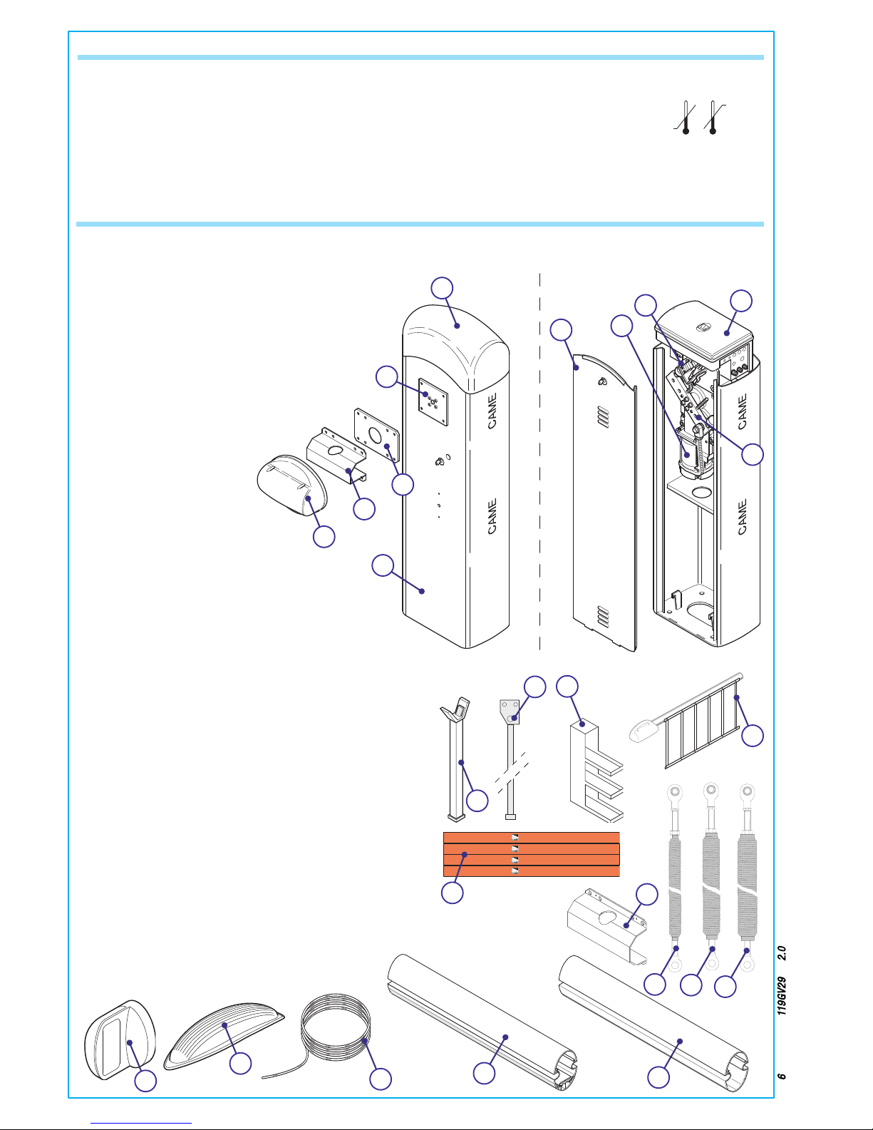
4.3 Parts description
AUTOMATION UNIT
ACCESSORIES
1)
G03750 - Semioval aluminium bar, painted white L = 4 m.
2)
G03752 - Oval aluminium bar, painted white L = 4 m.
3)
G02040 - Ø40 (yellow) balancing spring
4)
G04060 - Ø50 (green) balancing spring
5)
G06080 - Ø55 (red) balancing spring
6)
G0465 - Rack
7)
G02802 - upport for DIR photoelectric cells
8) G028401 - Luminous cord
9)
G02807 - Fixed barrier support
10)
G02808 - Mobile barrier support
11)
G02809 - Adhesive reflector strips
12)
G02801 - Flashing dome lamp
13)
G03751 - Emergency battery housing support
14)
G03753 - Attachment flange for elyptical bar
11 -
CAME
CAME
CAME
CAME
VIEW FROM THE BAR
SUPPORT BRACKET
VIEW FROM INSPECTION
HATCH
1)
Upper dome
2)
Bar beam plate
3)
Bar fitting intermediate plate
4)
Cover for semioval aluminium bar
5)
Anti-shearing protection cover
6)
Sheet-steel or stainless steel cabinet with
galvanized and painted finish
7)
Inspection hatch
8)
Gearmotor
9)
Lever
10)
End stop unit
11)
ZL38 Control panel
7
1
2
3
4
5
7
12
11
9
2
3
4
6
5
GEARMOTOR
Power supply: 120V A.C. 50/60Hz
Motor power supply: 24V D.C.
Max. absorption: 15A (24V)
Rated power: 300W
Max. torque: 600 Nm
Reduction ratio: 1/202
Opening time: 2 - 6 seconds
Operative intermittence: intensive operation
Protection level: IP54
Weight: 110 lb
Insulation class: I
13
1
14
10
6
9
10
11
Pag. 7 - Manual code: 119G V2 9 ver. 2.0 09/2010 © CAME cancelli automatici s.p.a. - The data and information reported in this installation manual are susceptible to change at any time and without obligation on CAM E cancelli automatici s.p.a. to notify users.
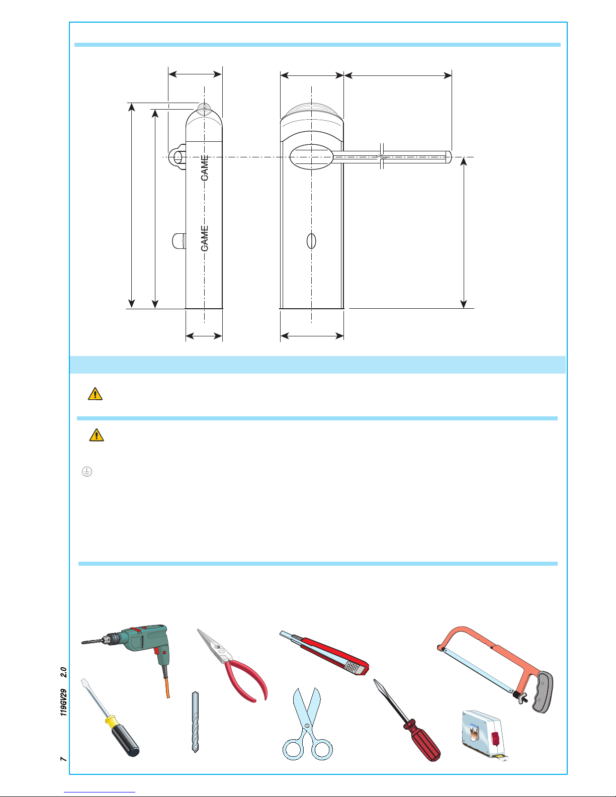
Make sure all tools and materials necessary are within reach to install the edge in maximum safety, according to
regulations in force. The following figure illustrates the minimum equipment for the installer.
Before proceeding with the installation, it is necessary to:
• Make sure the area selected for the mounting of the base and for the unit itself presents no hazards
• Provide for suitable omnipolar disconnection device with more than 3 mm between contacts to section power supply
• Connections inside the case made for protection circuit continuity are allowed as long as they include additional
insulation with respect to other internal drive parts
• Install suitable tubes and ducts for electric cable passage to guarantee protection against mechanical damage
5 Installation
4.4 Size measurements
5.1 Preliminary checks
5.2 Tools and materials
46”
8.5”
13”
12.6”
40”
13.4”
max. 147.6”
34.8”
(inches)
Installation must be carried out by expert qualified personnel and in full observance of regulations in force.
Pag. 8 - Manual code: 119G V2 9 ver. 2.0 09/2010 © CAME cancelli automatici s.p.a. - The data and information reported in this installation manual are susceptible to change at any time and without obligation on CAM E cancelli automatici s.p.a. to notify users.
Note: An evaluation of the size of the cables with lengths other than the data in the table must be made based on the effective
absorption of the connected devices, according to the local electrical code standards.
For connections that require several loads on the same line (sequential), the size given on the table must be re-evaluated based on
actual absorption and distances.
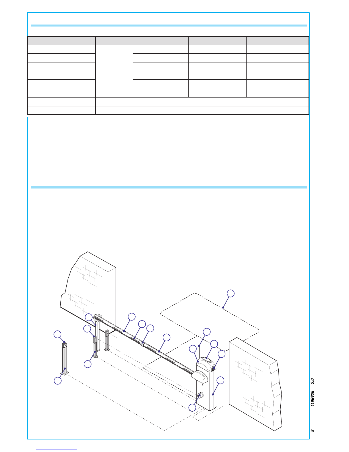
1 - G4140ZU unit
2 - Control panel
3 - Aluminium bar
4 - Red phosphorescent strips
5 - Luminous cord
6 - Movement-indicating flashing lamp
7 - Column for photoelectric cells
8 - Photoelectric cells
9 - Fixed barrier support
10 - Magnetic sensor
11 - Photoelectric cell support
12 - Magnetic reader
13 - Column for reader
5.3 Cable list and minimun thickness
Connections Type of cable Length of cable 3 < 32ft Length of cable 32 < 65ft Length of cable 65 < 100ft
120V AC power supply
UL LISTED
CABLE/WIRE
3G x 14 AWG 3G x 14 AWG 3G x 14 AWG
Photoelectric cells TX 2 x 20 AWG 2 x 20 AWG 2 x 20 AWG
Photoelectric cells RX 4 x 18 AWG 4 x 18 AWG 4 x 18 AWG
24V power supply accessory 2 x 20 AWG 2 x 20 AWG 2 x 20 AWG
Safety and control divices 2 x 18 AWG 2 x 18 AWG 2 x 18 AWG
Antenna connection RG58 max. 32 ft
Metallic mass detector (see documents provided with product)
5.4 Standar installation
RX
TX
C
AM
E
CAME
2
1
7
3
4
5
6
8
9
10
11
12
13
14
15
16
Pag. 9 - Manual code: 119G V2 9 ver. 2.0 09/2010 © CAME cancelli automatici s.p.a. - The data and information reported in this installation manual are susceptible to change at any time and without obligation on CAM E cancelli automatici s.p.a. to notify users.
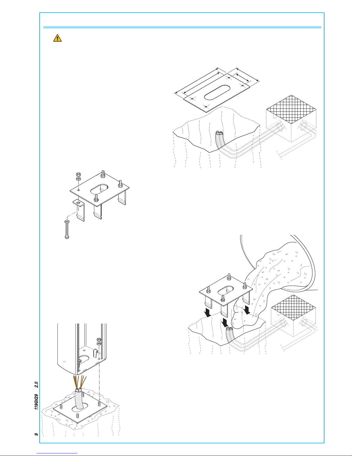
5.5 Fitting for unit base
The following applications are only examples, as the space required for unit installation and the accessories vary
depending on dimensions and therefore it is up to the installer to select the best solution.
18
9.45
15
5.51
- Assemble the four anchoring clamps at the base.
- Prepare a hole to house the fixing base and prepare sheath
tubes from the branch pit for the connections.
Note: The number of tubes depends on the type of system and
the accessories you will hook up.
- Remove the nuts and washers from the threaded screws, position the cabinet on the base in
correspondence with the 4 threaded screws and secure with the nuts and washers.
Note: We recommend installing the cabinet with the inspection hatch facing the internal area.
- Fill the hole with concrete and immerge the clamps and the fixing
base, paying particular attention to the sheath tube which must go
through the hole at the base. The base must be perfectly level, clean
and with the screw threads fully on the surface.
Pag. 10 - Manual code: 119G V2 9 ver. 2.0 09/2010 © CAME cancelli automatici s.p.a. - The data and information reported in this installation manual are susceptible to change at any time and without obligation on CAME cancelli automatici s.p.a. to notify users.
SX
1
3
N
M
PT F FC
FA
4
2
DX
SX
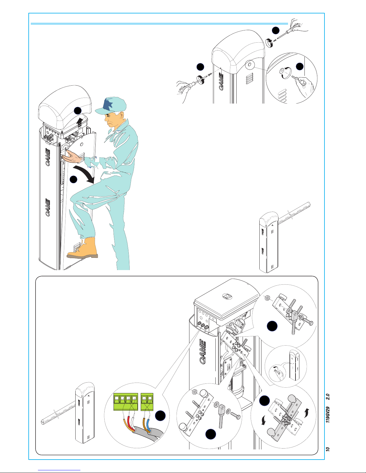
5.6 Installation of the Unit
- Remove the two screws from the top crown, insert the key
into the slot and turn it counter-clockwise.
1
1
2
4
3
- Should installation on the right be required, the direction of
the bar’s opening must be inverted. Proceed in the following
manner:
- remove the anchor bolt for springs from the transmission
arm (1)
- release the gearmotor with the key
- turn the transmission arm around (2)
- secure the gearmotor again;
- secure the anchor bolt to the transmission arm’s opposite
hole (3)
- invert the end stop wires on terminals M and N,FA and FC
(4).
DX
- Lift the top crown and remove the cabinet door.
- The barrier is designed to
be installed on the left of the
gateway as seen from inside.
 Loading...