

Page 1
G2500 - G2500N
INSTALLATION MANUAL
OPERATOR
FOR STREET BARRIERS
Englis
h
119GM02EN
Page 2

WARNING!
Important instructions for the safety of people:
READ CAREFULLY!
Foreword
• Use of the products must be restricted to its intended use
(i.e. that for which it was expressly built for). Any other use is
to be considered dangerous. Came Cancelli Automatici S.p.A.
is not liable for any damage resulting from improper, wrongful
or unreasonable use • Keep these warnings with the installation and use manuals issued with the automated system.
Before installing
(preliminary check: in case of a negative
outcome, do not proceed before having
complied with the safety obligations)
• Make sure that the parts you intend to automate are in
good working order, and that they are properly balanced
and aligned. Also, make sure that proper mechanical stops
are already in place • If the operator will be installed at a
height of less than 2.5 m from the ground or other access
level, check whether you will need any protections and/or
warnings • Any gate leaves, fi tted with pedestrian entrances,
onto which you will install an operator, must have a blocking
mechanism when the gate is in motion • Make sure that the
opening of the automated gate is not an entrapment hazard
as regards any surrounding fi xed parts • Do not mount the
operator upside down or onto any elements that may fold
under its weight. If needed, add suitable reinforcements at
the points where it is secured • Do not install onto gates on
either an upward or downward slope (i.e. that are not on fl at,
level ground) • Check that any lawn watering devices will not
wet the gearmotor from the bottom up.
Installation
• Carefully section off the entire site to prevent unauthorised
access, especially by minors and children • Be careful when
handling operators that weigh more than 20 Kg (see installation manual). In such cases, employ proper weight handling
safety equipment • All opening commands (e.g. buttons, key
selectors, magnetic detectors, etc.) must be installed at least
1.85 m from the gate’s area of operation perimeter - or where
they cannot be reached from the outside of the gate. Also,
the direct commands (e.g. push button, or proximity devices,
etc.) must be installed at a height of at least 1.5 m and must
not be accessible to the public • All ‘maintained action’ commands, must be placed where the moving gate leaves, transit
areas and driveways are completely visible • If missing, apply a permanent label that shows the position of the release
mechanism • Before delivering to the client, verify that the
system is EN 12453 (impact test) standard compliant. Make
sure that the operator has been properly adjusted and that the
safety and protection devices, as well as the manual release
are working properly • Where necessary and in plain sight,
apply the Warning Sings (e.g. gate plate).
Special instructions and
advice for users
• Keep the gate’s area of operation clean and clear of any
obstacles. Trim any vegetation that may interfere with the
photocells • Do not allow children to play with the fi xed command devices, or in the gate’s area of operation. Keep any
remote control devices (i.e. transmitters) away from the children as well • Frequently check the system, to see whether
any anomalies or signs of wear and tear appear on the moving
parts, on the component parts, on the securing points, on the
cables and any accessible connections. Keep any joints (i.e.
hinges) lubricated and clean, and do the same where friction may occur (i.e. slide rails) • Perform functional tests on
photocells and sensitive edges, every six months. Keep glass
panels constantly clean (use a slightly water-moistened cloth;
do not use solvents or any other chemical products) • If the
system requires repairs or modifi cations, release the operator
and do not use it until safety conditions have been restored
• Cut off the power supply before releasing the operator for
manual openings. See instructions • Users are FORBIDDEN
to carry out ANY ACTIONS THAT THEY HAVE NOT BEEN
EXPRESSLY ASKED TO DO OR SO INDICATED in the manuals. Any repairs, modifi cations to the settings and extraordinary maintenance MUST BE DONE BY THE TECHNICAL
ASSISTANCE STAFF • On the periodic maintenance log, note
down the checks you have done.
Special instructions and
advice for all
• Avoid working near the hinges or moving mechanical parts
• Stay clear of the gate’s area of operation when in motion •
Do not resist the direction of movement of the gate; this may
present a safety hazard • At all times be extremely careful
about dangerous points that must be indicated by proper
pictograms and/or black and yellow stripes • When using
a selector or command in ‘maintained action’ mode, keep
checking that there are no people in the area of operation of
the moving parts. Do this until you release the command •
The gate may move at any time without warning • Always cut
the power when cleaning performing maintenance.
Page 3
Page 4
p.
2
2 - Manual code:
119G M02
119 GM 02 ver.
4
4 05/2013 © CAME Cancelli Automatici S.p.A. - The data and information in this manual may be changed at any time and without obligation on the part of Came Cancelli Automatici S.p.A . to notify said changes.
ENGLISH
Legend of symbols
This symbol shows parts which must be read with care.
This symbol means the parts which describe safety issues.
This symbol tells you what to tell the end-user.
The GARD operator is designed and built by CAME Cancelli Automatici S.p.A.
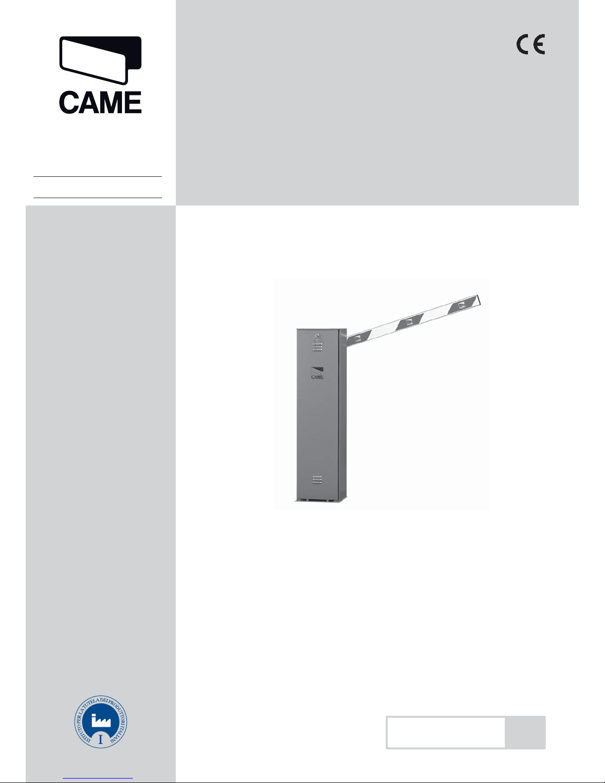
G2500/G2500N - Barrier with irreversible, 230 V AC gearmotor, galvanised steel cabinet, control panel and internal command.
NB - You must request right or left-side barriers when ordering. In this manual only left-hand barriers are shown.
Required accessories:
G0251 - White varnished, aluminium barrier-arm with 60x40 mm section, L = 2700 mm.
Optional accessories:
G0461 - Package of re ecting red strips;
G0462 - Fixed rest for barrier-arms;
G0257 - Joint for the G0251 (maximum length of the barrier-arm is 2.0 m).
Important! Make sure that the command and safety equipment and accessories are CAME originals; this ensures easy and safe
installation and maintenance for your system.
4 Description
“IMPORTANT SAFETY INSTALLATION INSTRUCTIONS”
“WARNING: IMPROPER INSTALLATION MAY RESULT IN SERIOUS HARM. PLEASE FOLLOW ALL INSTALLATION INSTRUCTIONS”
“THIS MANUAL IS INTENDED ONLY FOR PROFESSIONAL INSTALLERS OR OTHER COMPETENT INDIVIDUALS”
4.1 Gearmotor
2.1 Intended use
2 Conditions of use
The GARD automatic barrier is designed to be used in both public and private parking facilities, and in residential settings.
Any installation and use other than that specified in this manual is forbidden.
3 Reference standards
2.2 Limitations to use
Passage width up to 2 metres with 5 to 4 seconds opening time.
C am e C an ce l li Au to ma ti c i e mp lo y s a n I SO 9 00 1:14 00 1 c er ti f ie d quality management system and an ISO 14001 environmental
management system. Came entirely engineers and manufactures in Italy.
This product is compliant with: see statement of compliance.
Page 5
3
4
8
5
2
6
7
1
9
p.
3
3 - Manual code:
119G M02
119 GM 02 ver.
4
4 05/2013 © CAME Cancelli Automatici S.p.A. - The data and information in this manual may be changed at any time and without obligation on the part of Came Cancelli Automatici S.p.A . to notify said changes.
ENGLISH
4. 2 Technical data
4.3 Technical description
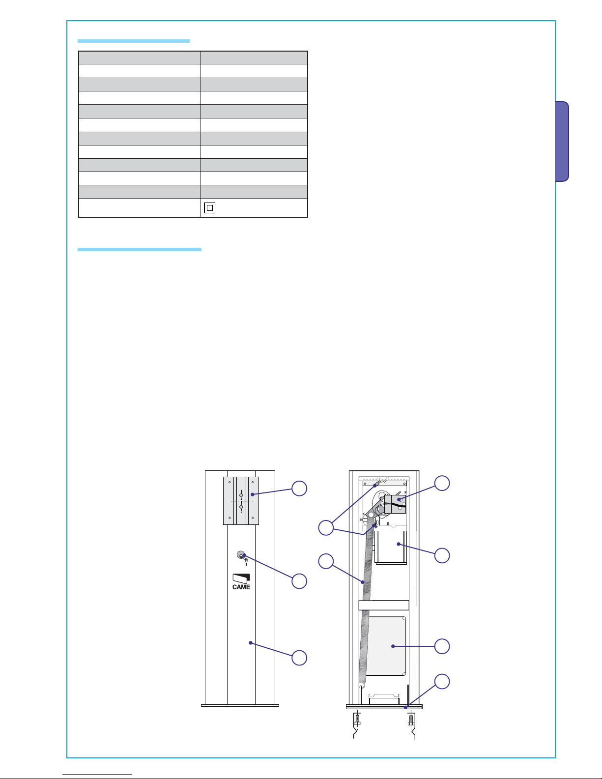
OPERATOR ASSEMBLY UNIT
1. Steel sheeting cabinet, 2 mm thick with galvanised finish. Var n i s h e d ( G 2 5 0 0 , R A L 2 0 0 4 , G 2 5 0 0 N t e x t u r e d g r e y ) . I n s p e c t i o n f l a p
with customised key.
2 . G a l v a n i s e d f i n i s h , s t e e l a n c h o r i n g - b a s e c o m p l e t e w i t h f o u r c l amps and relative nuts and bolts for fastening the cabinet to the
floor.
3. Barrier-arm attachment flange with galvanised finish. for blocking the barrier-arm quickly and safely.
4. - Gearmotor release activated by a customised key.
5. 230 V AC powered motor. Irreversible gearmotor with cast aluminium casing. inside of which operates a worm-screw based
reduction system with permanent fluid grease lubrication. All rotating elements are fitted on permanently-lubricated ballbearings or self-lubricating ball-joints.
6. Counter-weight movement balancing spring.
7. Inner mechanical safety stops.
8. Limit-switch assembly.
9. ZC5 Control panel
Power supply 230 V AC - 50 / 60 50/60 Hz
Motor power supply 230 V AC - 50 / 60 50/60 Hz
Maximum draw.
1 A
Power rating 120 W
Maximum Torque. 70 Nm
Reduction ratio 1/2 02
Opening interval 4 s
Duty cycle 30%
Protection rating IP54
Weight 40 Kg
Working temperature - 20° / + 55°
Insulation class
Page 6
260
265 220
275
=
1007
884
=
p.
4
4 - Manual code:
119G M02
119 GM 02 ver.
4
4 05/2013 © CAME Cancelli Automatici S.p.A. - The data and information in this manual may be changed at any time and without obligation on the part of Came Cancelli Automatici S.p.A . to notify said changes.
ENGLISH
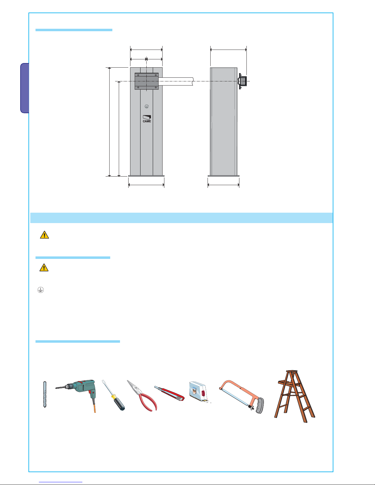
Make sure you have all the tools and materials needed to carry out the installation in total safet y and in accordance with current
regulations. The figure shows some examples of the tools needed by installers.
Before installing the operator, do the following:
• Check that the installing the operator does not create and hazardous situations;
Set up a suitable omnipolar cut-off device, with distances greater than 3 mm between contacts, with se ctioned power supply;
•
Check that any connections inside the container (made for continuity purp oses of the protective circuit) be f itted with ex tra
insulation compared to other internal conductive parts;
• Set up proper conduits and electric cable raceways, making sure these are protected from any mechanical damage;
Installation must be carried by skilled, qualified technicians in accordance with current regulations.
5 Installation
4.4 Overall dimensions
Measurements in mm
5.1 Preliminary checks
5.2 Tools and equipment
Page 7
1
3
7
6
4
10
8
5
9
2
p.
5
5 - Manual code:
119G M02
119 GM 02 ver.
4
4 05/2013 © CAME Cancelli Automatici S.p.A. - The data and information in this manual may be changed at any time and without obligation on the part of Came Cancelli Automatici S.p.A . to notify said changes.
ENGLISH
N.B. If cables are of a different length than that shown in the table, determine the cable section based on the ac tual draw and the numb er
of connected devices and according the what is set forth in the CEI EN 60204-1 code of regulations.
For connections requiring several loads on the same line (i.e. sequential ones), the dimensions shown on the table must be reconsidered
according to the total draw and actual distances.
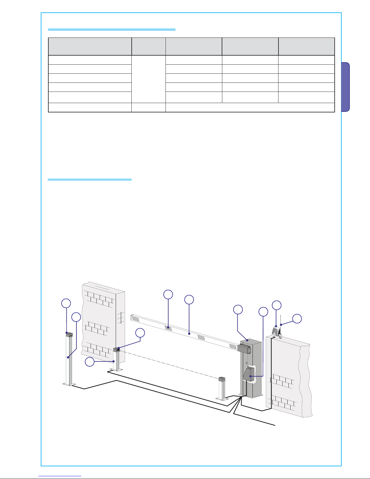
1. GARD unit
2. Control panel
3. Aluminium barrier arm
4. Red reflective strips
5. Movement flashing light
6. Small post for photocells
7. Safety photocells
8. Sensor post
9. Transponder sensor
10. Antenna
5.3 Type of cable and minimum thicknesses
5.4 Standard installation
Connection for
Type of
cable
Cable length
1 < 10 m
Cable length
10 < 20 m
Cable length
20 < 30 m
Power supply 230 V 2F
FROR CEI
20-22
CEI EN
50267-2-1
3G x 1.5 mm
2
3G x 2.5 mm
2
3G x 4 mm
2
Photocell transmitters 2 x 0.5 mm
2
2 x 0.5 mm
2
2 x 0.5 mm
2
Photocell receivers 4 x 0.5 mm
2
4 x 0.5 mm
2
4 x 0.5 mm
2
Accessories power supply 24 V DC 2 x 0.5 mm
2
2 x 0.5 mm
2
2 x 1 mm
2
Safety and command devices 2 x 0,5 mm
2
2 x 0.5 mm
2
2 x 0.5 mm
2
Antenna connection RG58 max. 10 m
Page 8

R
p.
6
6 - Manual code:
119G M02
119 GM 02 ver.
4
4 05/2013 © CAME Cancelli Automatici S.p.A. - The data and information in this manual may be changed at any time and without obligation on the part of Came Cancelli Automatici S.p.A . to notify said changes.
ENGLISH
5.5 Setting up the operator base
The following illustrations are just examples, in that the space for securing the operator and accessories depends on
the overall measurements. It is up to the installer to choose the most suited solution.
- Assemble the four anchoring clamps to the plate.
- Dig a pit for the anchoring base and set up the required corrugated
tubes for the connections coming out of the junction pit.
N.B. the number of tubes depends on the type of installation
and accessories used.
- Remove any protruding nuts or washers, position the cabinet onto the base and fasten it.
Note: install the cabinet with the inspection ap facing an easily accessible direction.
- Fill the pit with cement and sink the anchoring base (that is, the plate
+ clamps) making sure the corrugated tubes pass through he hole set
up on the plate and that they are not lled with cement. The base must
be perfectly level, clean and with the bolt threading completely on the
surface.
Wait at least 24 hrs for everything to solidify.
Page 9

A
C
B
p.
7
7 - Manual code:
119G M02
119 GM 02 ver.
4
4 05/2013 © CAME Cancelli Automatici S.p.A. - The data and information in this manual may be changed at any time and without obligation on the part of Came Cancelli Automatici S.p.A . to notify said changes.
ENGLISH
5.6 Assembly
- Proceed with installing the unit: we
suggest setting up the cabinet so that
the inspection flap points inwards
(see p. 8).
Assemble the barrier-arm while
calculating the proper length and
fasten it to the arm-supporting
attachmentA using the four supplied
bolts.
Adjust the barrier vertically and
horizontally by using the respective
inner B and C mechanical
stops .
The spring supplied with the G2500 barrier is calibrated for barrier longer than 1.8 m.
WARN ING!
The release ac tion may result in dan ger for the us er, when, for
whatever reason - the arm is im prope rly f ixed to th e pin durin g
mounting, the arm is bro ken or cracked during an accident,
e t c ! T h i s m a y r e s u l t i n s u d d e n r o t a t i n g m o v e m e n t s o f t h e a r m
attachment and/or of the arm itself.
LockingRelease
For barrier-arms less than 1.8 m, release the gearmotor, and modify the spring at tachment as
shown in the figure.
Page 10

p.
8
8 - Manual code:
119G M02
119 GM 02 ver.
4
4 05/2013 © CAME Cancelli Automatici S.p.A. - The data and information in this manual may be changed at any time and without obligation on the part of Came Cancelli Automatici S.p.A . to notify said changes.
ENGLISH
6 Description of the control panel
FUSE TABLE
to protect: fuses for:
Electronic board (line) 5 A-F
Accessories 1 A-F
TECHNICAL DATA
line voltage 230 V - 50/60 Hz
Maximum allowed power load 500W
power draw 1A max
circuit insulation class
container material ABS
Engineered and built entirely by Came Cancelli Automatici S.p.A.
The control panel is powered at 230V a.c., with 50/60Hz of maximum frequency.
The command devices and accessories are powered by 24V.
Warning!The accessories must not exceed 20 W overall.
All connections are protected by quick fuses, see table.
The card provides and controls the following functions:
- automatic closing after an opening command;
- Reopening while closing
The available command modes are:
- opening/closing;
-opening/closing with maintained action;
- total stop.
Special trimmers regulate:
- the working time for automatic closing;
- the working time;
Optional accessories:
- barrier open warning-light, when barrier-arm is raised;
- barrier closed warning-light, when barrier-arm is lowered.
WARNING: Cut o the main power before acting inside the equipment.
5.7 R/L barrier
Right-hand
BARRIER
Left-hand
BARRIER
Entrance
side
Inner zone
Entrance
side
Inner zone
To change sense of rotation, request documentation from your local dealer or contact CAME in your country (see last page, otherwise go
to www.came.com).
Page 11

5
3
8
9
7
6
2
1
4
10
12
11
p.
9
9 - Manual code:
119G M02
119 GM 02 ver.
4
4 05/2013 © CAME Cancelli Automatici S.p.A. - The data and information in this manual may be changed at any time and without obligation on the part of Came Cancelli Automatici S.p.A . to notify said changes.
ENGLISH
1. Transformer
2. Working time adjuster trimmer
3. Automatic closing time adjuster trimmer
4. Radio frequency card socket
5. Connecting terminals
6. Transformer terminals
7. Antenna connection terminals
8. Line fuse
9. Accessories fuse
10. Code memorising button
11. "Feature selection" Dip-switch
12. Condenser
6.1 Main components
N.B.: Fixed motor torque: keep the
indicated faston on position 4.
Page 12

COM
NC
NC
COM
p.
10
10 - Manual code:
119G M02
119 GM 02 ver.
4
4 05/2013 © CAME Cancelli Automatici S.p.A. - The data and information in this manual may be changed at any time and without obligation on the part of Came Cancelli Automatici S.p.A . to notify said changes.
ENGLISH
230 V AC motor
Closing microswitch (F-FC)
Opening microswitch (F-FA)
Accessories power supply
Power supply at 230 V AC, Frequency 50 / 60 Hz
Orange
Brown
Black
Blue
6.2 Electrical connections
The swing-joint in the picture (which is factory made) is for a left-hand barrier (see par. 5.7).
Gearmotor, limit switch
Terminals for powering the 24V AC accessories.
Overall allowed power: 20W
Orange
Page 13

p.
11
11 - M anual code:
119G M02
119 GM 02 ver.
4
4 05/2013 © CAME Cancelli Automatici S.p.A. - The data and information in this manual may be changed at any time and without obligation on the part of Came Cancelli Automatici S.p.A . to notify said changes.
ENGLISH
Opening button (N.O. contact)
- Barrier-arm opening command.
Command devices
Warning devices
Barrier down/closed warning light Contact rated for: 24 V - 3 W Max.
- Noti es that the barrier is lowered. It turns o when the barrier is raised.
Closing button (N.O. contact)
- Barrier-arm closing command.
Stop button ((N.C.) contact.)
- Button to stop barrier arm. Excludes automatic closing. To resume movement press the command button or transmitter key.
If unused, short-circuit contact 1-2.
Barrier raised/open warning-light Contact rated for: 24 V - 3 W Max.
- Signals that barrier-arm is raised, and switches of when the barrier-arm is
lowered.
230 V AC output for ashing light:
- Flashes while barrier opens and closes.
Command devices
if unused
Page 14

TX
RX
TX
./ # .#
RX
#
#
p.
12
12 - Manual code:
119G M02
119 GM 02 ver.
4
4 05/2013 © CAME Cancelli Automatici S.p.A. - The data and information in this manual may be changed at any time and without obligation on the part of Came Cancelli Automatici S.p.A . to notify said changes.
ENGLISH
DIR
Safety devices
"Reopening when closing (N.C.) Contact»
- Input for safety devices like photocells, compliant with
law EN 12978. While the barrier is lowering, opening the
contact will invert movement until it is fully raised.
if unused, short-circuit contact 2-C1.
"Reopening when closing (N.C.) Contact»
if unused, short-circuit contact 2-C1.
if unused
if unused
Delta-S
DOC Delta
6.3 Selecting functions
1 ON - Automatic closing activated; (1OFF - deactivated)
2 - Unused, keep DIP swith on OFF
Page 15

L1 L2 U V W E 10 11 1 2 3 4 C1 F FA FC
L1 L2 U V W E 10 11 1 2 3 4 C1 F FA FC
2-3 2-4 1-2 2-C1
p.
13
13 - Manual code:
119G M02
119 GM 02 ver.
4
4 05/2013 © CAME Cancelli Automatici S.p.A. - The data and information in this manual may be changed at any time and without obligation on the part of Came Cancelli Automatici S.p.A . to notify said changes.
ENGLISH
6.4 Settings
Connecting two barriers joined by a single command
Make the connections on terminals A, then connect the 2 terminals as shown.
Motor A terminals
Motor B terminals
TCA Trimmer = Adjusting automatic closing time, from a minimum of 5 seconds to a maximum of 60 seconds.
TL Trimmer = Adjusting working time from a minimum of 15 seconds to a maximum of 120 seconds.
Page 16

TOP TAM / TWIN
p.
14
14 - Manual code:
119G M02
119 GM 02 ver.
4
4 05/2013 © CAME Cancelli Automatici S.p.A. - The data and information in this manual may be changed at any time and without obligation on the part of Came Cancelli Automatici S.p.A . to notify said changes.
ENGLISH
7 Activating the radio command
Connect RG58 antenna cable to the apposite terminals.
Antenna
Fit the radio-frequency card into the electronic board only AFTER CUTTING OFF THE POWER SUPPLY.
N.B.: The electronic card recognises the radio-frequency card only when it is powered up.
AF card
Only for the AF43S / AF43SM radio-frequency cards.
- position jumper as shown depending on the series of transmitters you are using.
Radio frequency card
Frequency
MHz
Card
Radio-frequency
Series
transmitters
FM 26,995 AF130 TFM
FM 30.900 AF150 TFM
AM 26.995 AF26 TOP
AM 30.900 AF30 TOP
AM 433.92 AF43 S / AF43SM TAM / TOP
AM 433.92 AF43TW TWIN (KeyBlock)
AM 433.92 AF43SR ATOMO
AM 40.685 AF40 TOUCH
AM 863.35 AF868 TOP
Page 17

ATOMO
AT01 • AT02
AT04
CAME
CAME
CAME
TOUCH
TCH 4024 • TCH 4048
TOP
TOP-432A • TOP-434A
TOP-302A • TOP-304A
C
AME
CAME
CAMECAM
E
TOP
TOP-432NA • TOP-434NA
TOP-862NA • TOP-864NA
TOP-432S
TWIN
TWIN 2 • TWIN 4
TAM
T432 • T434 • T438
TAM-432SA
CAME
CAME
CAME
CAME
CAME
CAME
CAME
CAME
CAME
TFM
T132 • T134 • T138
T152 • T154 • T158
p.
15
15 - Manual code:
119G M02
119 GM 02 ver.
4
4 05/2013 © CAME Cancelli Automatici S.p.A. - The data and information in this manual may be changed at any time and without obligation on the part of Came Cancelli Automatici S.p.A . to notify said changes.
ENGLISH
Radio card
PROG bu t to n
- Keep button pressed PROG button on the
electronic card. The LED ashes ON and OFF.
- Press the button on the transmitter to be memorised.
The LED will stay ON to con rm memorisation is OK.
Flashing LED LED on
Memorisation
N.B.: if you later wish to change code, just repeat the above sequence.
see instruction sheet in the packaging
of the AF43SR radio-frequency card
Tra nsmitter s
see instructions on box
Each coding is identi ed by a di erent way of ashing:
1 - In TAM mode coding - two ashes plus one pause
2- In TOP mode coding - continuous ashing
3 - Key-Block mode coding - three ashes plus one pause
Page 18

p.
16
16 - Manual co de:
119G M02
119 GM 02 ver.
4
4 05/2013 © CAME Cancelli Automatici S.p.A. - The data and information in this manual may be changed at any time and without obligation on the part of Came Cancelli Automatici S.p.A . to notify said changes.
ENGLISH
8 Safety instructions
This product is only intended to be used for the purpose it was designed. Any other use is therefore improper and dangerous. The
manufacturer is not liable for any damage caused by improper, wrongful or unreasonable use.
Stay away from working mechanical parts. Stay out of the working range of the moving operator.
Do not oppose the movement of the operator as this may result in danger.
D o n o t a l l o w c h i l d r e n t o p l a y t o l o i t e r within the working range of the operator. Keep transmitters and any other command devices
away from children, to prevent the operator from being activated by mistake.
Immediately stop using the operator if any anomaly is manifested.
Danger of hand crushing
Danger high voltage
Transit forbidden during
operation
Important general safety instructions
9 Maintenance
9.1 Periodic maintenance
Periodic serv icing performed by end-user are wiping clean the photocell's glass front pieces and checking for proper
working state of safety devices and that the operator is free of any obstacles.
We also suggest to periodically check the state of lubrication and tightness of screws on the operator.
T o c h e c k t h e e f f i c i e n c y o f t h e s a f e t y d e v i c e s , w a v e a n o b j e c t i n f r o n t o f t h e p h o t o c e l l s d u r i n g c l o s i n g c y c l e , i f t h e o p e r a t o r inverts
or halts its movement, the photocells are working properly. This is the only maintenance job that can be done with the springtension of the barrier loaded.
Before performing any job we highly recommend to cut off the main p ower, to prevent any dangerous situations from possible
accidental movements by the barrier.
-To wipe clean the photocell glass, use a slightly damp cloth, and do not use any solvents or other chemical products that may
ruin the device.
- Check that the photocells are free of any vegetation blocking them, and that there are no obstacles to the free movement of
the arm.
Page 19

p.
17
17 - M anual code:
119G M02
119 GM 02 ver.
4
4 05/2013 © CAME Cancelli Automatici S.p.A. - The data and information in this manual may be changed at any time and without obligation on the part of Came Cancelli Automatici S.p.A . to notify said changes.
ENGLISH
Periodic maintenance log to be done by users (every 6 months)
Date Notes Signature
9.2 Extraordinary maintenance
The following table is used to log extraordinar y maintenance, repair and improvement jobs done by the specialised external
firms.
N.B. All extraordinary maintenance jobs must be carried out by skilled technicians.
Extraordinary maintenance log
Installer's stamp Product name
Date of job
Technician's signature
Customer's signature
Job carried out _______________________________________________________________________________________
__________________________________________________________________________________________________
_______________________________________________________________________________________________
Page 20

p.
18
18 - Manual code:
119G M02
119 GM 02 ver.
4
4 05/2013 © CAME Cancelli Automatici S.p.A. - The data and information in this manual may be changed at any time and without obligation on the part of Came Cancelli Automatici S.p.A . to notify said changes.
ENGLISH
Installer's stamp Product name
Date of job
Technician's signature
Customer's signature
Job carried out _______________________________________________________________________________________
__________________________________________________________________________________________________
_______________________________________________________________________________________________
9.3 Troubleshooting
PROBLEM REF. CHECK
The operator neither opens nor closes
1-2-3-4 6-8-18
1 - Lock the inspection hatch using the key and check the release
lock
The operator opens but does not shut. 4-7-10 2 - Deactivate the "maintained action" function via Dip-switch
The operator closes but does not open 4-7-9 3 - Check power supply and fuses
The operator does not carry out the automatic
closing
11-12-13 4 - The N.C. safety contacts are open
The radio-control does not work 2-14-16 6 - Deactivate the master-slave function
The operator inverts the direction of travel 7-18 7 - Check balancing and taughtness of springs
Only one radio-control works. 22 8 -Deactivate the obstacle detection function via dip switch
The photocell does not work 12-23-24 9- Check opening limit-switch
The led warning light flashes quickly 4 10- Check closing limit-switch
The led warning light stays lit. 13 11- Activate "automatic closing" via the Dip-switch
The operator does not fully complete cycle 7 12 - Check for the proper direction of travel
Cannot balance the arm 7-15 13 - Check the command devices
The operator does not decelerate 7-15
14 - Cut off and bring back power to card or check the TOP/TAM
jumper on the AF43S card
The operator does not run on the emergency
batteries
8-25-26 15 - Check the Arm length/applied accessories ratio”
The operator is slow when starting 7 Memorise the radio code again
18 - Adjust sensitivity
22 - Enter or duplicate the same code in all transmitters
23 - Activate the photocell via Dip-switch
24 - Connect the photocells in series and not in parallel fashion
25 - Check the batteries
26 - Respect the polarities when powering up the photocells
Installer's stamp Product name
Date of job
Technician's signature
Customer's signature
Job carried out _______________________________________________________________________________________
__________________________________________________________________________________________________
_______________________________________________________________________________________________
Page 21

p.
19
19 - Manual code:
119G M02
119 GM 02 ver.
4
4 05/2013 © CAME Cancelli Automatici S.p.A. - The data and information in this manual may be changed at any time and without obligation on the part of Came Cancelli Automatici S.p.A . to notify said changes.
ENGLISH
10 Dismantling and disposal
O n i t s p r e m i s e s , C A M E C a n c e l l i A u t o m a t i c i S . p . A . i m p l e m ents a certifie d Environmental Management System in com-
pliance with the UNI EN ISO 14001 standard to ensure environmental protection.
P l e a s e h e l p u s t o s a f e g u a r d t h e e n v i r o n m e n t . A t C A M E w e b e l i e v e t h i s t o b e o n e o f t h e f u n d a m e n t a l s o f o u r s m a r k e t o p e r a t i o n s
and development strategies. Just follow these short disposal instructions:
DISPOSING OF THE PACKAGING
The components of the packaging (i.e. cardboard, plastic, etc.) are solid urban waste and may be disposed of without much
trouble, simply by separating them for recycling.
Before proceeding it is always a good idea to check your local legislation on the matter.
DO NOT DISPOSE OF IN NATURE!
PRODUCT DISPOSAL
Ou r p rodu ct s a re m ad e up of vari ou s ma te ria ls. M os t of t he se (aluminium, plastic, iron, electric cables) are solid urban waste.
These can be disposed of at local solid waste management dumps or recycling plants.
Other components (i.e. electronic cards, remote control batteries, etc. ) may contain hazardous substances.
These must therefore be handed over the specially authorised disposal firms.
Before proceeding it is always a good idea to check your local legislation on the matter.
DO NOT DISPOSE OF IN NATURE!
Page 22

www. came.com
www. came.com
CAME Can celli Au to matic i S.p.a.
CAME Cancelli Automatici S.p.a.
Via Martiri Della Libertà, 15
31030
Dos son D i Cas ier
Dosson Di Casier (Tv)
(+39) 0422 4940
(+39) 0422 4941
Assi stenza Tecni ca/Nu mero Verde 800 2 95830
Assistenza Tecnica/Numero Verde 800 295830
IT • Per ogni ulteriore informazione su azienda, prodotti e assistenza nella vostra lingua:
EN • For any further information on company, products and assistance in your language:
FR • Pour toute autre information sur la société, les produits et l’assistance dans votre langue :
DE • Weitere Infos über Unternehmen, Produkte und Kundendienst bei:
ES • Por cualquier información sobre la empresa, los productos y asistencia en su idioma:
NL • Voor meer informatie over het bedrijf, de producten en hulp in uw eigen taal:
PT • Para toda e qualquer informação acerca da empresa, de produtos e assistência técnica, em sua língua:
PL •
Wszystkie inne informacje dotyczące fi rmy, produktów oraz usług i pomocy technicznej w Waszym języku znajdują się na stronie:
RU •
Для получения дополнительной информации о компании, продукции и сервисной поддержке на вашем языке:
HU • A vállalatra, termékeire és a műszaki szervizre vonatkozó minden további információért az Ön nyelvén:
HR • Za sve dodatne informacije o poduzeću, proizvodima i tehničkoj podršci:
UK • Для отримання будь-якої іншої інформації про компанію, продукцію та технічну підтримку:
Engl ish
English - Manual cod e:
119GM 02
119 GM 02 ver.
4
4 05/2013 © CAME Cancelli Auto matici S.p.A.
The data and informatio n in this manual may be changed at any time and without obligation on the part of Came Cancelli Automatici S.p. A. to notify said changes.
 Loading...