

Page 1
SERIE BZ |
BZ
SERIES
|
SÉRIE BZ |
BAUREIHE
BZ |
SERIE BZ
Documentazione
Tecnica
M23
rev. 3.1
11/2003
©
CAME
CANCELLI
AUTOMATICI
CANCELLI AUTOMATICI
AUTOMAZIONE
PER CANCELLI
SCORREVOLI
10
AUTOMATION
SYSTEM FOR
SLIDING GATES
4
1 - 2 - 3
BZ - BZ1
AUTOMATISATION
POUR POURTAILS
COULISSANTS
9
5
4
ANTRIEBE
FÜR
SCHIEBETORE
10
9
6
119BM23
AUTOMATIZACIÓN
PARA CANCELAS
CORREDERAS
7
8
2 x 1,5
RG58
2 x 1 - TX
3 x 1.5 / 230V
2 x 1
4 x 1 - RX
11
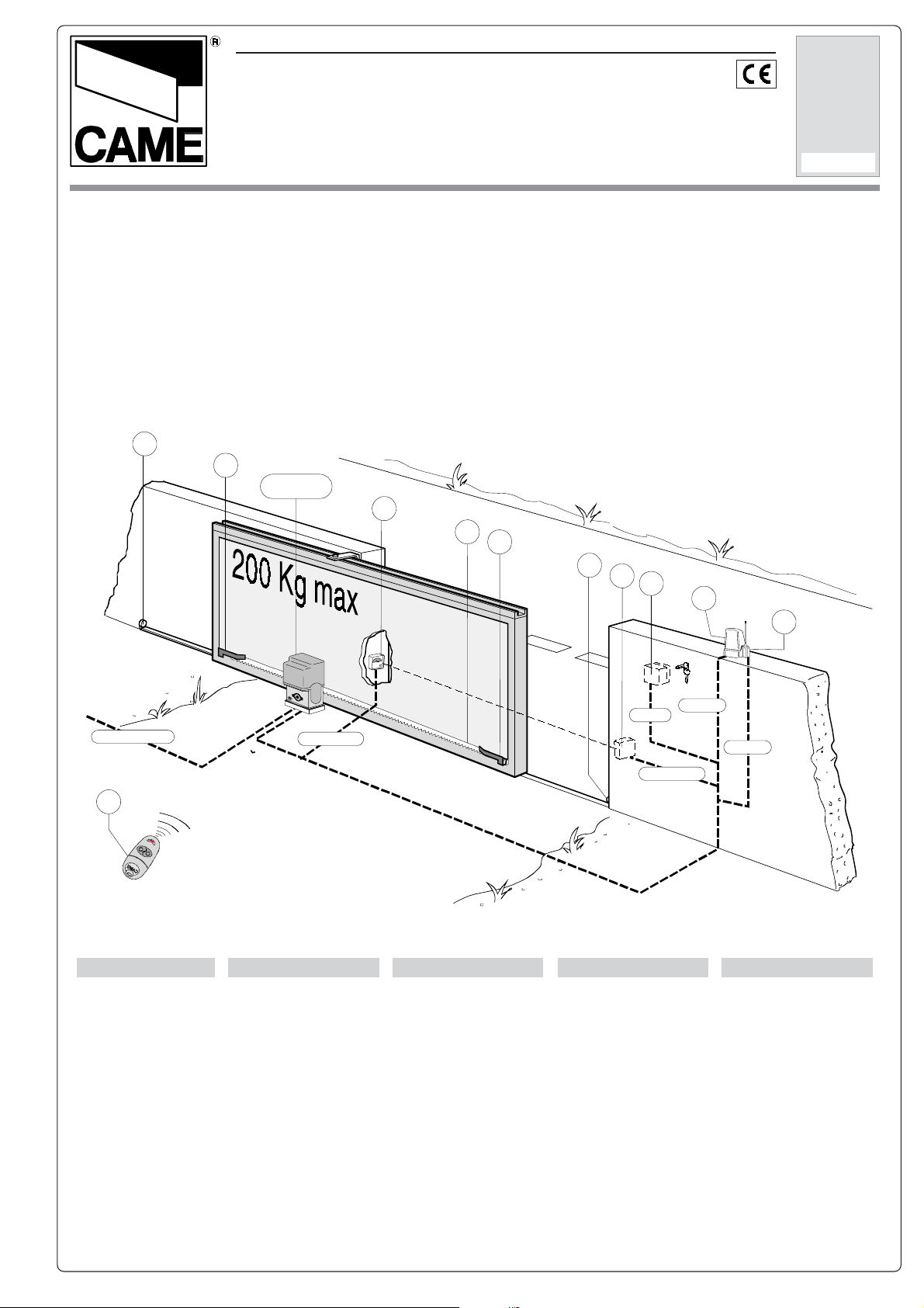
Impianto tipo Installation type Standard montage Instalación tipo
1 - Motoriduttore BZ/
BZ1
2 - Quadro comando
3 - Ricevitore radio
4 - Alette finecorsa
5 - Cremagliera
6 - Selettore a chiave
7 - Lampeggiatore
8 - Antenna
9 - Fotocellule
10 - Fermo anta
11 - Trasmettitore
Standard installation
1 - BZ/BZ1 gearmotor
2 - Control panel
3 - Radio receiver
4 - Limit-switch tabs
5 - Rack
6 - Key-switch selector
7 - Flashing light
8 - Antenna
9 - Photocells
10 - Closure stop
11 - Transmitter
1 - Motoréducteur BZ/
BZ1
2 - Armoire de
commande
3 - Récepteur radio
4 - Buttées fin de corse
5 - Crémaillère
6 - Sélecteur a clé
7 - Clignotant
8 - Antenne
9 - Photocellules
10 - Butée d'arrêt
11 - Emetteur
1 - BZ/BZ1
Getriebemotor
2 - Schalttafel
3 - Funkempfänger
4 - Endschalterwinkel
5 - Zahnstange
6 - Schlüsselschalter
7 - Blinkleuchte
8 - Antenne
9 - IR Lichtschranke
10 - Toranschlag
11 - Sender
1 - Motorreductor BZ/
BZ1
2 - Cuadro de mando
3 - Radiorreceptor
4 - Aletas de tope
5 - Cremallera
6 - Selector a llave
7 - Lámpara
intermitente
8 - Antena
9 - Fotocélulas
10 - Tope puerta
11 - Transmisor
Page 2
CARATTERISTICHE GENERALI -
ALLGEMEINES -
GENERAL SPECIFICATIONS
CARACTERÍSTICAS GENERALES
- CARACTÉRISTIQUES GÉNÉRALES
Progettato e costruito
interamente dalla
CAME CANCELLI
AUTOMATICI S.p.A.,
risponde alle vigenti
norme di sicurezza ,
con grado di
protezione IP 54.
Scheda BN1 di
collegamento e
ricarica per batteria di
emergenza (escluse) e
staffa di supporto per
le stesse, inclusa nel
modello BZ1 e
opzionale nel modello
BZ.
Portata massima:
Kg 200.
Garantito 24 mesi
salvo manomissioni.
Modelli
BZ: scheda BN1
opzionale.
BZ1: scheda BN1
inclusa.
Designed and
constructed entirely by
CAME CANCELLI
AUTOMATICI S.p.A., it
complies with the safety
regulations in force,
with IP 54 degree of
protection.
BN1 connection card
and recharging device
for emergency battery
(excluded) and support
bracket for these,
included in the BZ1
model and optional in
the BZ model.
Maximum capacity:
200 kg
24-month guarantee
except for tampering.
Models
BZ: BN1 board optional.
BZ1: BN1 board included.
Conçu et construit
entièrement par CAME
CANCELLI
AUTOMATICI S.p.A.,
conforme aux normes
en vigueur en matière
de sécurité, avec
degré de protection IP
54.
Carte BN1 de
branchement,
recharge pour batterie
d’urgence (exclues) et
bride de support pour
ces dernières,
comprise dans le
modèle BZ1 et en
option pour le modèle
BZ.
Charge maximum:
200 kg.
Garantie 24 mois sauf
en cas d’altérations.
Modèles
BZ: carte BN1 en option.
BZ1: carte BN1
comprise
Komplett von der Firma
CAME CANCELLI
AUTOMATICI S.p.A.
unter Berücksichtigung
der geltenden
Sicherheitsnormen und
mit Schutzklasse IP54
entwickelt und
konstruiert.
Karte BN1 zum
Anschließen und
Aufladen von
Notbatterien (nicht
mitgeliefert) und
Halterungsbügel für die
Batterien, inbegriffen
bei Modell BZ1 und als
Optional erhältlich bei
Modell BZ.
Maximale Tragkraft:
200 kg
Garantie: 24 Monate.
Kein Garantieanspruch
bei Veränderungen.
Modelle
BZ: Karte BN1 Optional.
BZ1: Karte BN1
inbegriffen.
Diseñado y fabricado
completamente por
CAME CANCELLI
AUTOMATICI S.p.A.,
responde a las normas
de seguridad vigentes
, con grado de
protección IP 54.
Tarjeta BN1 de
conexión y recarga
para baterías de
emergencia
(excluidas) y estribos
de soporte respectivo,
incluida en el modelo
BZ1 y opcional en el
modelo BZ.
Capacidad de carga
máxima: 200 kg.
Garantía de 24 meses,
salvo alteración del
producto.
Modelos
BZ: tarjeta BN1
opcional.
BZ1: tarjeta BN1 incluida.
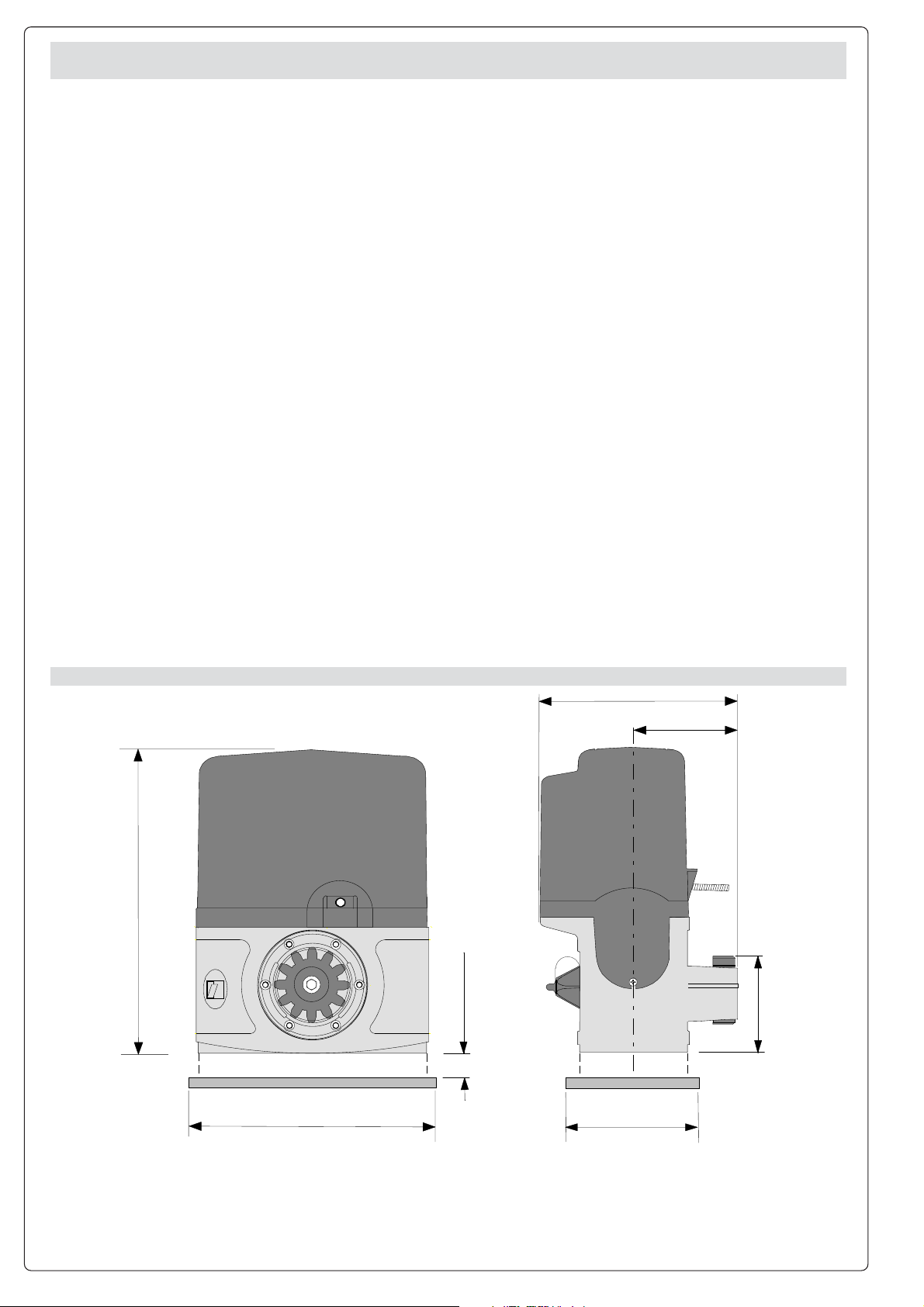
MISURE D'INGOMBRO -
290
OVERALL DIMENSIONS
240
- MEASURES D'ENCOMBRENT -
16 max.
ABMESSUNGEN
185
98
130
- MEDIDAS
105
2
Page 3

CARATTERISTICHE TECNICHE -
TECNISCHE DATEN -
TECNICHAL CARACTERISTICS -
CARACTERISTICAS TECNICAS
CARACTERISTIQUES TECNIQUES
EROTTUDIROTOMOSEPENOIZATNEMILAOTNEMIBROSSA
ROTOMRAEGTHGIEWYLPPUSREWOPTNERRUCXAM
RUETCUD…ROTOMSDIOPNOITATNEMILANOITPROSBA
ROTOMEBEIRTEGTHCIWEG-ROSREVMORTS
ROTCUDERROTOMOSEPNOICATNEMILAAICNEBROSBA
1ZB/ZB gK9
PRIMA DELL'INSTALLAZIONE ....
VOR DEN INSTALLATION ÜBERPRÜFEN....
- Controllare che
l'anta sia rigida e che
le ruote di
scorrimento siano in
buono stato e
adeguatamente
ingrassate.
- La guida a terra
dovrà essere ben
fissata al suolo,
completamente in
superficie in tutta la
sua lunghezza e priva
di irregolarità che
possano ostacolare il
movimento del
cancello.
- I pattini-guida
superiori non devono
creare attriti.
- Prevedere una
battuta d'arresto in
apertura e una in
chiusura ed il
percorso dei cavi
elettrici come da
impianto tipo.
- The gate must be
sufficiently rigid and
solid.
- The wheels on which
the gate slide must be
in perfect condition and
adequately lubricated.
- The wheel guide must
be firmly attached to
the ground, completely
exposed, and without
any irregular sections
which might hinder the
movement of the gate.
- The upper guide must
allow for the correct
amount of play in order
to guarantee smooth
and silent movement of
the gate.
- Aperture and closure
stops must be installed.
- The wiring must be
routed as specified by
the control and safety
requirements.
XAM
WARD
XAM
GNUG
.c.aV032
.c.dV42
XAM
EMHANFUAMORTS
XAM
A7 W071 %05 05/1 N003 .nim/m21
- BEFORE INSTALLING ..... -
- Le rail de guidage
devra être bien fixée
au sol. De plus, il
devra se présenter
entièrement en
surface sans
irrégularités (qui
pourraient empêcher
le mouvement du
portail).
- Le guide supérieur
devra avoir un jeu
convenable avec le
portail (pour
permettre un
mouvement régulier
et silencieux).
- Prévoir une butée
d’arrêt à l’ouverture
et à la fermeture.
- Prévoir le passage
des câbles
électriques selon les
dispositions de
commande et de
sécurité.
AZNETOP
XAM
XAM
REWOP
ECNASSIUP
XAM
XAM
GNUTSIEL
AICNETOP
XAM
AZNETTIMRETNI
OROVAL
YTUD
ELCIC
ECNETTIMRETNI
LIAVARTED
REUADTLAHCSNIESGNUZTESRETNU
AICNETIMRETNI
OJABART
IDOTROPPAR
ENOIZUDIR
NOITCUDER
OITAR
EDTROPPAR
NOITCUDER
SINTLÄHREV
EDNOICALER
NOICCUDER
ATNIPS
XAM
XAM
HSUP
E…SSUOP
XAM
XAM
RERABLEGER
EJULPME
XAM
AVANT D'INSTALLER L'AUTOMATISME .....
- ANTES DE INSTALAR EL AUTOMATISMO .....
- Die Leistungfähigkeit
der feststehenden und
beweglichen Teile des
Tores überprüfen.
- Das Tor sollte
ausreichend stabil sein.
- Die Gleitrollen sollten
in guten Zustand und
angemessen
geschmiert sein.
- Die Gleitführung auf
dem Boden sollte sich
in optimaler Position
befinden: gut auf dem
Boden befestigt, in
seiner Gesamtlänge
vollständig über dem
Boden, ohne
Vertiefungen und/oder
Unebenheiten, die die
Torbewegung
behindern können.
- Die oberen
Führungsschienen
sollten das richtige
Spiel zum Tor haben,
um ein präzises und
regelmäßiges Gleiten
zu garantieren.
- Einen Anschlag für
Tor Auf und Tor Tu
sollte vorhanden sein.
- Den Lauf der
elektrischen Kabel nach
den Steuerungs- und
Sicherheitsbestimmungen
vorsehen.
- La hoja de la puerta
debe estar
suficientemiente
rigida y compacta
- Las ruedas de
deslizamiento deben
estar perfecta y
engrasadas
adecuada-mente.
- La guia de
deslizamiento debe
estar bien fijada en el
suelo, sobresaliendo
a lo largo de su
entera longitud, sin
irregularidades (que
podrian obstaculizar
el movimiento de la
puerta).
- La guia superior
debe tener el justo
juego con la puerta
metálica (para
garantizar un
movimiento regular y
silencioso).
- Disponer un tope
para apertura y el
cierre.
- Disponer un
conducto para los
cables eléctricos que
cumpla con las
disposiciones de
mando y seguridad.
'ATICOLEV
XAM
XAM
DEEPS
ESSETIV
XAM
XAM
SGNUGARTREBÜ
DADICOLEV
XAM
3
Page 4
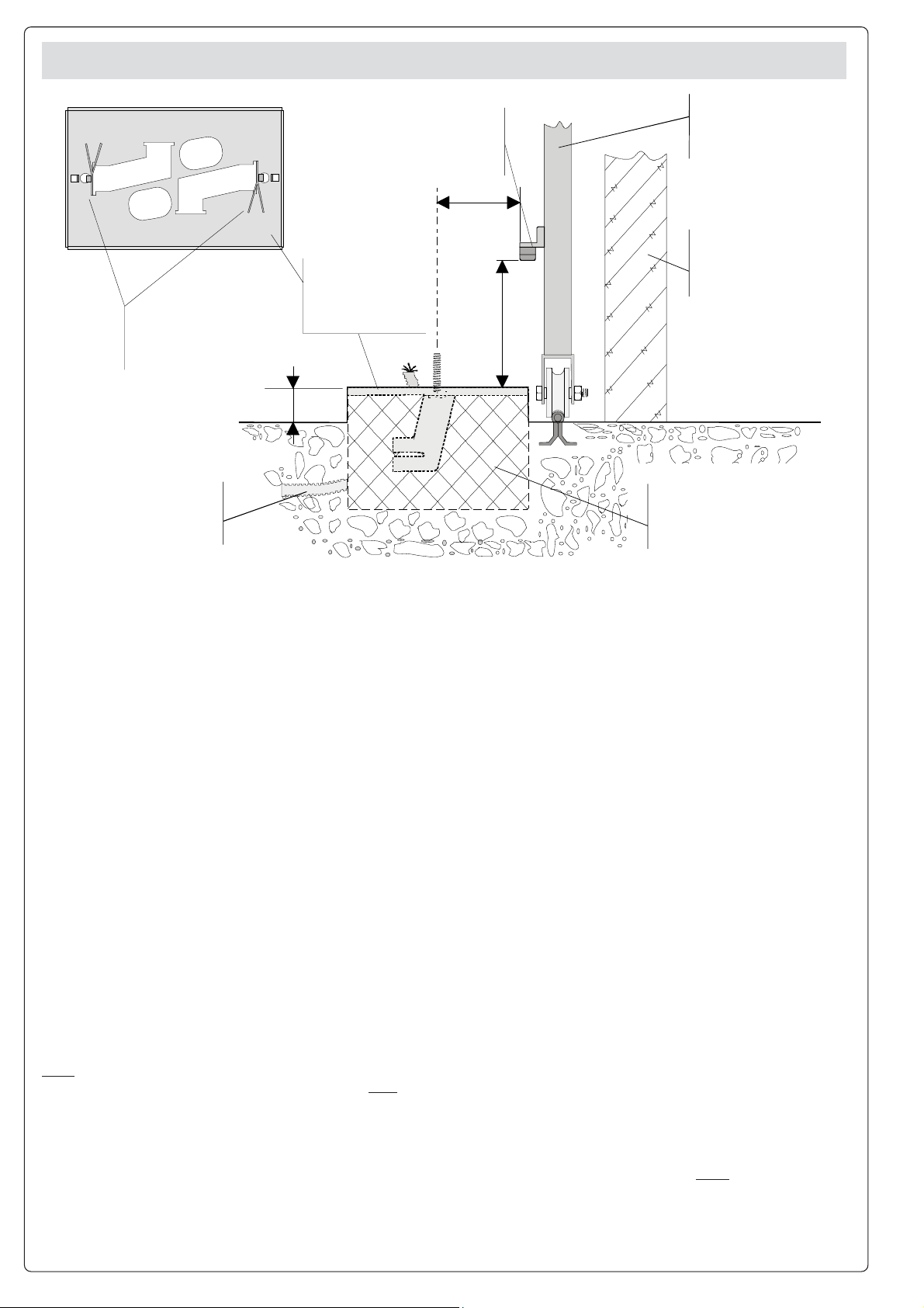
FISSAGGIO BASE MOTORE -
BEFESTIGUNGS DER MOTORBASIS
Zanche
Anchorstays
Agrafes
Verankerung
BarrasdefijciÛn
MOTOR TO BASE ANCHOREGE
- FIJACIÓN BASE MOTOR
Cremagliera
Rack-limit
CremaillÈre
Zahnstange
Cremallera
76
Piastradiancoraggio
Fixingplate
Plaquedefixation
Gleitachse
PlacadefijaciÛn
50
- FIXATION DE LA PLAQUE DU MOTEUR
cancello
Gate
portail
Tore
Puerta
Strutturafissa
Wall
Structrurefixe
FesteStruktur
Estructurafija
105
C‚ bles
Cables
Inserire le viti nella
piastra di ancoraggio
bloccandole con un
dado, ed estrarre le
zanche preformate
verso il basso.
Predisporre, dimensionandola in base
alle misure del
motoriduttore, una
piazzola in cemento
(si consiglia di farla
sporgere dal terreno
di circa 50 mm) con
annegata la piastra di
ancoraggio e relative
zanche sulla quale
sara' fissato il
gruppo.
La base di fissaggio
dovra' risultare
perfettamente in bolla,
pulita in tutte le sue
estremita', con il
filetto delle viti
completamente in
superfice.
N.B.: Dalla stessa
dovranno emergere i
tubi flessibili per il
passaggio dei cavi di
collegamento
elettrico.
Cavi
Cable
Kabel
Install the screws in the
anchor plate and
fasten them with a nut,
then bend the preformed clamps
downwards.
Construct a cement
foundation that is large
enough to accomodate
the gear motor (it is a
good idea to protrude
50 mm from the
ground). When pouring
the foundation, embed
the gear motor anchor
plate and the relative
clamps in the cement.
The anchor bolts
should be embedded
in the concrete in the
positions indicated;
the drive unit is then
attached to this bots.
The anchor plate must
be perfectly level and
absolutly clean; the
bolts threads must be
completly exposed.
N.B.: The flexible tubes
for the electrical wiring
must be embedded in
the base and protude
in the correct position.
Introduire les vis dans
la plaque d'ancrage
en les bloquant avec
un écrou, et replier les
agrafes préformées
ver le bas.
Préparer une base en
ciment d'une
dimension adéquate
aux mesures du
motoréducteur (il est
conseillé de la faire
dépasser du terrain
d'environ 50 mm), et
noyer dedans la
plaque d'ancrage et
les agrafes
correspondantes afin
de permettre le fixage
du groupe.
La base de fixation
devrà être
parfaitement de
niveau et propre sur
toute sa surface et le
filet des vis devra être
complètement en
surface.
N.B. Les câbles pour
le branchement
électrique devront
sortir de cette base.
4
Piazzolaincemento
Concretebase
Plate-formeenciment
Plattenachse
Plataformadecemento
Die Schrauben in die
Ankerplatte einfügen
und mit einer
Schraubenmutter
blockieren, die
vorgeformten
Fundamentanker nach
unten umbiegen.
Eine den
Abmessungen des
Getriebemotors
entsprechende
Betonfunda-mentplatte
(Es empfiehlt sich,
diese ca. 50 mm vom
Boden herausragen zu
lassen) zum Einbetten
der Ankerplatte und
der
entsprechendenFundamentanker, die zur
Befestigung des
Antriebsaggregats
dienen, vorbereiten.
Die
Befestigungsunterlage
muß in seiner
gesamten Länge
vollkommen eben und
sauber sein. Das
Gewinde der
Schrauben müssen
gänzlich. hervorstehen.
Wichtig: die Kabel für
den Elektroanschluß
müssen herausrgen.
Introducir los
tornillos en la
placa de anclaje,
bloqueándolos con
una tuerca, y doblar
las palancas
preformadas hacia
abajo (bloqueando de
esa forma los
tornillos).
Preparar, dándole las
dimensiones
adecuadas en función
de las medidas del
motorreductor, una
plataforma de
cemento (se aconseja
dejarla sobresalir del
suelo aprox. 50 mm)
con la placa de
enclaje embedida y
con las
correspondientes
varillas, que permitrá
la fijación del grupo.
La base de fijación
debe estar
perfectamente
nivelada, limpia en
todos sus extremos,
con la rosca de los
tornillos totalmente in
superficie.
N.B.: De ésta deben
sobresilar los tubos
flexibles para el paso
de los cables para las
conexiones
eléctricas.
Page 5
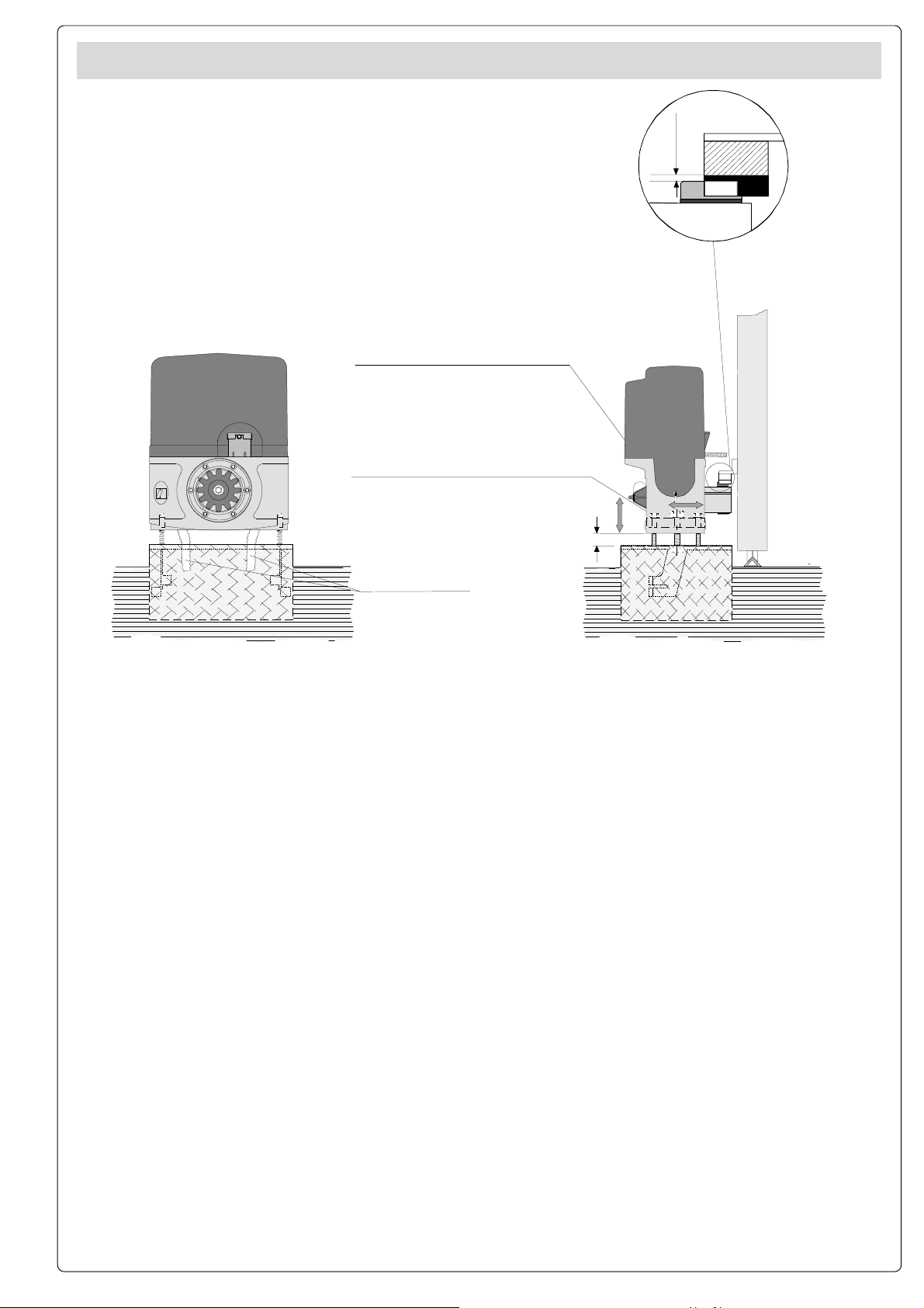
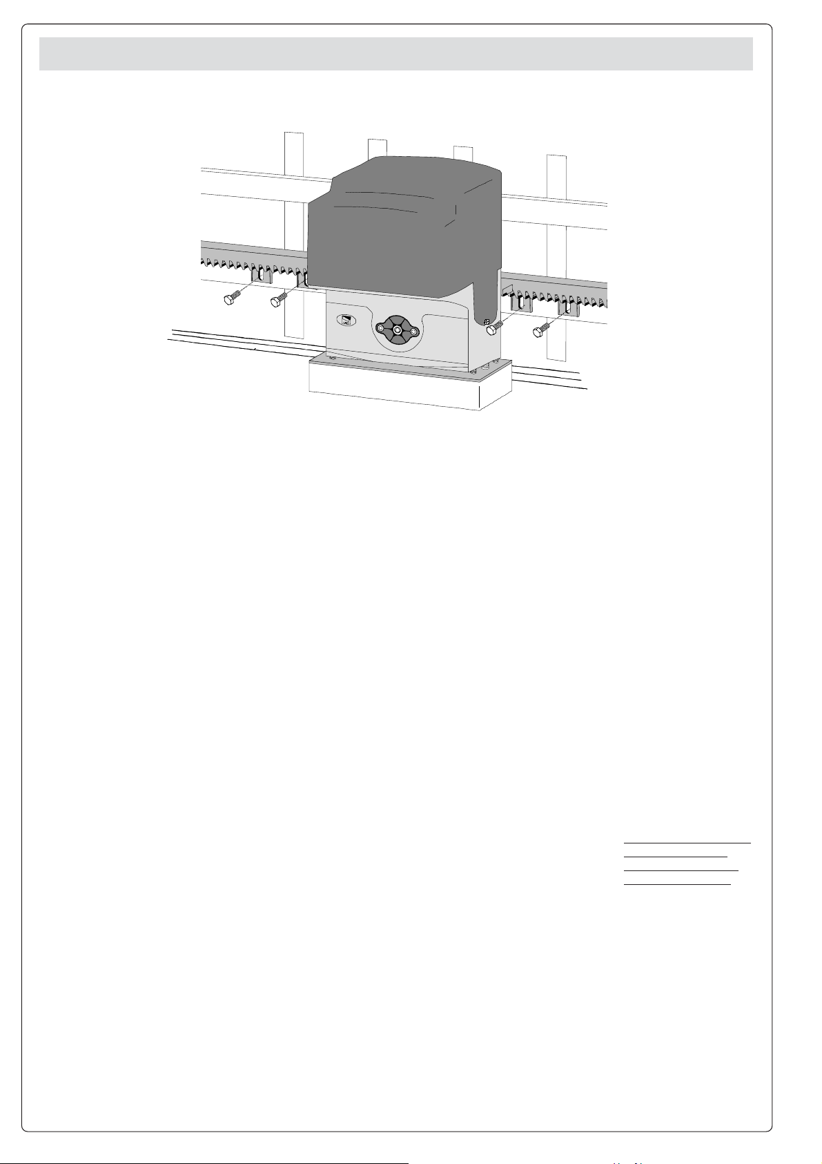
POSA DEL GRUPPO -
UNIT INSTALLATION -
AUFSTELLUNG DES AGGREGATS
Accoppiamento pignone-cremagliera
con gioco 1-2 mm.
Rack to pinion coupling
with 1÷2 mm. clearance
Assemblage pignon-crémaillère avec jeu
de 1 à 2 mm.
Zwischen Zahnstange und dem Antriebsritzel
1÷2 mm. Spiel einstellen
Acoplamento piñon-cremaliera
1÷2 mm. de juego
Regolazione orizzontale e fissaggio
Horizontal adjustment unit and achorage
Réglage horizontal et fixation
Horizontale Einstellung
Regulación horizontal y fijación
Regolazione verticale - messa in bolla
Vertical adjustment and unit leveling
Réglage vertical - mise à niveau
Vertikale Einstellung
Regulación vertical y nivelación
INSTALALTION DU GROUPE
- COLOCACIÓN DEL GRUPO
1÷2 mm.
Nella fase
preliminare di posa,
i piedini dovranno
sporgere di 5-10
mm. per permettere
allineamenti,
fissaggio della
cremagliera e
regolazioni
successive.
L'accoppiamento
esatto con la linea di
scorrimento del
cancello è ottenibile
dal sistema di
regolazione
integrale
(brevettato)
composto da:
- le asole che
permettono la
regolazione
orizzontale;
- i piedini filettati in
acciaio che
permettono la
regolazione
verticale e la messa
in bolla;
- le piastrine e i dadi
di fissaggio che
rendono solidale
l'aggancio del
gruppo alla base.
Ingresso cavi
Cable entrances
Passage des câbles
Kabeleinführungen
Entrada cables
During the initial
phase of installation,
the feet should
protude by 5-10 mm.
in order to allow for
alignment,
anchorage of the
rack and further
adjustments.
Perfect alignment
with the guide rail is
made possible by the
(patented) built-in
regulation system,
wich consists of:
- slots for horizontal
adjustment;
- threaded steel feet
for vertical
adjustment and
levelling;
- plates and bolts for
anchorage to the
base.
Dans la phase de
pose préliminaire,
les broches devront
dépasser de 5 à 10
mm afin de
permettre les
alignements et les
réglages
nécessaires après
la pose.
L’accouplement
exact avec la ligne
de coulissement du
portail s’effectue par
le système de
réglage hauteur
(breveté) dont le
groupe est pourvu,
et qui comprend
plus précisément:
- les trous oblong
permettant le
réglage horizontal;
- les broches
filetees en acier qui
donnent le réglage
vertical et la mise à
niveau;
- les plaques et les
écrous de fixation
qui assemblent
solidement le
groupe à la plaque
de fixation scellée.
5÷10 mm.
Während der
Vorbereitungsarbeiten
der Montage sollten
die Füße 5-10 mm
herausragen, um
Ausfluchtungen und
Einstellung auch
nach der
Fertigstellung zu
ermöglich.
Die genaue
Kopplung mit der
Gleitlinie des Tors
wird von dem
integrierten
Einstellungssystem
(patentiert)
garantiert, mit dem
das Aggregat
ausgestattet ist und
zwar:
- die Osen für die
horizontale
Einstellung,
- die Gewindefüße
aus Stahl für die
vertikale Einstellung
und die Nivellierung,
- die
Befestigungsplättchen
und -muttern zur
soliden Befestigung
des Aggregats an
die Bodenplatte.
En la fase previa del
emplazamiento, los
pies deben
sobresalir 5-10 mm
para consentir la
alineación, la
fijación de la
cremallera y las
regulaciones
sucesivas.
El acoplamiento
exacto con la linea
de deslizamiento de
la puerta metálica
se obtiene mediante
el sistema de
regulación integral
(patentado) que
consta de:
- los agujeros
ovalados que
consienten la
regulación
horizontal;
- los pies roscados
de acero que
permiten la
regulación vertical y
la nivelación;
- las placas y las
tuercas de fijación
que hacen solidario
el enganche del
conjunto con la
base.
5
Page 6
FISSAGGIO CREMAGLIERA -
MONTAGE DE ZAHNSTANGE -
ATTACHING THE RACK/LIMIT
FIJACIÓN DE LA CREMALLERA
- FIXATION CREMAILLÉRE
Fissare la
cremagliera sul
cancello come
segue:
- appoggiare la
cremagliera sul
pignone del
motoriduttore e far
scorrere
manualmente il
cancello fissando la
cremagliera in tutta
la sua lunghezza;
- ultimata
l'operazione di
fissaggio della
cremagliera,
regolare i piedini
(servendosi di un
cacciavite) in modo
da ottenere il giusto
giuoco tra pignone e
cremagliera (1-2
mm.).
N.B. : Questo evitera'
che il peso del
cancello vada a
gravare sul gruppo.
Se la cremagliera é
gia' fissata,
procedere direttamente alla
regolazione
dell'accoppiamento
pignone-cremagliera.
Eseguite tutte le
regolazioni, fissare il
gruppo stringendo i
dadi di fissaggio.
Attach the rack to the
gate as described
below:
- position the rack on
the pinion of the
gearmotor and slide
the gate manually in
order to attach the
rack along its entire
lenght;
- when the rack is
attached to the gate,
adjust the feet using a
screwdriver until the
play between the
pinion and the rack is
correct (1-2 mm.).
N.B. : This play
ensures that the
weight of the gate
does not rest on the
until.
If the rack is already
attached, proceed
directly to the
adjustment of the
rack/pinion coupling.
When the necessary
adjustment have
been completed,
fasten the unit in
position by tightening
the two anchor bolts.
Procéder à la fixation
de la crémaillère sur
le portail de la façon
suivante:
- Placer la
crémaillère sur le
pignon
motoréducteur et
faire coulisser le
portail manuellement
en fixant la
crémaillère sur toute
sa longueur.
- Lorsque la fixation
de la crémaillère est
terminée régler les
broches (en utilisant
un tournevis) de
façon à obtenir un
jeu convenable (1-2
mm) dans
l’accouplement du
pignon et de la
crémaillère.
N.B. Ceci pour éviter
que le poids du
portail ne repose sur
le groupe.
Si la crémaillère est
déjà fixée, utiliser le
système de réglage
hauteur pour
accopler de facon
exacte le pignon et la
crémaillère.
Exécuter tous les
réglages, fixer le
groupe en serrant
les deux écrous de
fixation.
Die Zahnstange auf
dem Getrieberitzel
anlehnen (nachdem
dieser in die
Eintriegelungsposition
gebracht wurde),
manuell das Tor
gleiten lassen und die
Zahnstange in seiner
gesamten Länge
befestigen.
Darauf achten, daß
bei
Metallzahnstangen im
Meterraster die
einzelnen Stücke
nicht auf Stoß montiert
werden, sondern auf
Fortlauf der Zahnung
(Zahnstange am Stroß
unten anlegen zur
Überprüfung).
Die verstellbaren
Füße des
Antriebsmotors (mit
einem
Schraubenzieher) so
einstellen, daß
zwischen Ritzel und
Zahnstange ein Spiel
(1-2 mm) besteht.
Dadurch wird
vermieden, daß das
Gewicht des Tores auf
dem Aggregat lastet.
Nach diesen
Einstellungsarbeiten
das Aggregat durch
Anziehen der beiden
Muttem befestigen.
Fijar la cremallera en
la puerta metálica
como se indica a
continuación:
- Apoyar la
cremallera en el
piñón motorreductor
y deslizar
manualmente la
puerta metálica
fijando la cremallera
a lo largo de su
entera longitud.
- Finalizadas las
operaciones para la
fijacion de la
cremallera, regular
los pies (por medio
de un destornillador)
de modo que se
obtenga el justo
juego entre el piñón y
la cremallera (1-2
mm).
N.B. Esto hace que el
peso de la puerta
metálica no cargue
bobre el conjunto.
Si la cremallera ya
ha sido fijada, hay
que regular el
acoplamiento piñóncremallera. Una vez
realizados los ajuste,
fijar el conjunto
cerrando las dos
tuercas de fijación.
6
Page 7

FISSAGGIO FINECORSA -
MONTAGE DE ENDSCHALTERBÜGEL -
ATTACHING THE SWITCH TABS
FIJACIÓN DE LA ALETAS DE TOPE
- FIXATION BUTTÉES FINS DE COURSE
- Posizionare sulla
cremagliera le alette
finecorsa che
determineranno, con
la loro posizione, la
misura della corsa.
Nota: evitare che il
cancello vada in
battuta contro il fermo
meccanico, sia in
apertura che in
chiusura.
- Position the limitswitch tabs (whose
positions determine
the limits of gate
travel) on the rack.
- Positionner les
ailettes de fin de
course sur la
crémaillère. Leur
position déterminera
la mesure de la
Note: do not allow the
course.
gate to strike the
mechanical stops in
the open or closed
positions.
Remarque: il faut
éviter que le portail se
porte en butée contre
l'arrêt mécanique,
aussi bien en
ouverture qu'en
fermeture.
SBLOCCO MOTORIDUTTORE -
ANTRIEBSENTRIEGELUNG
- Die EndschalterRippen, die durch ihre
Stellung den Torlauf
festlegen, auf der
Zahnstange
positionieren.
Hinweis: das Tor sollte
weder beim Öffnen
noch beim Schließen
auf den mechanischen
Endanschlag
auftreffen.
GEAR RELEASE
- OPÉRATION DE DÉBLOCAGE
- DESBLOQUEO MOTORREDUCTOR
- Colocar en la
cremallera las aletas
de final de carrera
que determinan, con
su posición, la medida
de la carrera.
Nota: evitar que la
puerta choque contro
el tope mecánico,
tanto en la apertura
como en el cierre.
Blocco (svitare completamente)
Engage (fully unscrew)
Blocage (dévisser complétement)
Blockierend (ganz ausschrauben)
Bloqueo (desenroscar completamente)
Sblocco (avvitare completamente)
Release (fully screw)
Déblocage (visser complétement)
Entriegelt (ganz einschrauben)
Desbloqueo (enroscar completamente)
7
Page 8

ITALIANOITALIANO
ITALIANO
La scheda comando va alimentata a 230V a.c.
sui morsetti L1 e L2 ed è protetto in ingresso
con fusibile da 1A.
I dispositivi di comandi sono a bassa tensione,
protetti con fusibile da 1.6A.
La potenza complessiva degli accessori a 24V,
non deve superare i 40W.
Le fotocellule possono essere collegate e
predisposte per:
-Riapertura in fase di chiusura;
-Stop parziale (arresto del cancello se in
movimento con conseguente predisposizione
alla chiusura automatica);
-Stop totale: questa funzione (arresta il cancello
con conseguente esclusione dell'eventuale ciclo
di chiusura automatica; per riprendere il
movimento bisogna agire sulla pulsantiera o sul
radiocomando).
- Dispositivo amperometrico vedi NOTA pag. 9
- Tempo di lavoro fisso 90".
ITALIANOITALIANO
Sicurezza
DESCRIZIONE TECNICA SCHEDA BASE ZN1
- Chiusura automatica. Il temporizzatore di
chiusura automatica si autoalimenta a finecorsa
in apertura. Il tempo prefissato regolabile, é
comunque subordinato dall'intervento di
eventuali accessori di sicurezza e si esclude
dopo un intervento di stop totale o in mancanza
di energia elettrica;
- Apertura parziale. Apertura del cancello per
passaggio pedonale, viene attivata collegandosi
ai morsetti 2-3P ed è regolabile mediante
trimmer AP.PARZ.. Con questa funzione, la
chiusura automatica varia nel seguente modo:
1) Dip 1 in ON Chiusura automatica attivata.
- Dopo un'apertura parziale, il tempo di chiusura
è indipendente dalla regolazione del trimmer
TCA, ed è fisso a 8".
2) Dip 1 in OFF Chiusura automatica
disattivata.
- Se il trimmer del TCA è regolato al minimo,
dopo un'apertura parziale non parte il conteggio
di chiusura automatica.;
- Se il trimmer del TCA è regolato al massimo,
dopo un'apertura parziale, il tempo di chiusura è
fisso a 8".
Funzioni selezionabili
-Trimmer SENS.= regolazione della sensibilità
amperometrica
-Rilevazione d'ostacolo: tale funzione annulla
ogni comando nel caso di ostacolo rilevato dalle
fotocellule (collegate in qualsiasi funzione di
sicurezza) con cancello a finecorsa;
-Funzione a «azione mantenuta». Funzionamento del cancello mantenendo premuto il
pulsante;
-Prelampeggio in apertura e chiusura;
-Tipo di comando:
- apre-stop-chiude-stop;
- apre-chiude-inversione;
- solo apertura.
Regolazioni
- Trimmer TCA = Tempo chiusura automatica:
da 1" a 120".
- Trimmer AP.PARZ. = Apertura parziale: da 1"
a 15".
Attenzione: prima di intevenire all’interno
dell’apparecchiatura, togliere la tensione.
ENGLISHENGLISH
ENGLISH
ENGLISHENGLISH
This control board is powered by 230V a.c.
across terminals L1 and L2, and is protected
by a 1A fuse on the main power line.
Control systems are powered by low voltage
and protected with by a 1.6A fuse.
The total power consumption of 24V
accessories must not exceed 40 W.
Photocells can be connected to obtain:
-Re-opening during the closing cycle;
-Partial stop (shutdown of moving gate, with
activation of an automatic closing cycle);
-Total stop (shutdown of gate movement
without automatic closing; a pushbutton or
radio remote control must be actuated to
resume movement);
-Amperometric safety device:
see NOTE pag.9;
- Fixed operating time of 90".
La carte de commande doit être alimentée
avec une tension de 230V sur les bornes L1 et
L2 et elle est protégée en entrée par un fusible
de ligne de 1A.
Les dispositifs de commande sont à basse
tension et protégés avec fusible de 1.6A.
La puissance totale des accessoires à 24V, ne
doit pas dépasser 40W.
Il est possible de brancher des photocellules
et de les programmer pour:
-Réouverture en phase de fermeture;
-Stop partiel (arrêt du portail, si en
mouvement, et conséquente programmation
pour la fermeture automatique);
-Stop total (arrêt du portail et désactivation
d’un éventuel cycle de fermeture automatique;
pour activer de nouveau le mouvement, il faut
agir sur les boutons-poussoirs ou sur la
radiocommande);
-Dispositif ampèremétrique: voir NOTE pag. 9;
-Temps de fonctionnement fixe de 90".
Safety
ANÇAIS
ANÇAIS
ANÇAIS
FR
FR
FRANÇAIS
FRANÇAISFR
Sécurité
TECHNICAL DESCRIPTION ZN1 MOTHERBOARD
- Automatic closing: The automatic closing
Functions available
timer is automatically activated at the end of
the opening cycle. The preset, adjustable
automatic closing time is automatically
interrupted by the activation of any safety
system, and is deactivated after a total stop
command or in case of power failure;
- Partial opening. Gate opening for passage on
foot is activated by connecting to the 2-3P
terminal blocks and it can be adjusted by the
AP.PARZ. trimmer.
By using this function, automatic closure
varies as follows:
1) Dip 1 ON - Automatic closure activated.
-after a partial opening, the closure time does
not depend on any adjustment of the TCA
trimmer, and is set at 8".
2) Dip 1 OFF - Automatic closure deactivated.
- If the TCA trimmer is set to the minimum,
after a partial opening, automatic closure
counting does not begin;
- If the TCA trimmer is set to the maximum,
after a partial opening, closing time
DESCRIPTION TECHNIQUE CARTE BASE ZN1
Fonctions pouvant être sélectionnées
- Fermeture automatique. Le temporisateur
de fermeture automatique est autoalimenté à
la fin du temps de la course en ouverture. Le
temps réglable est programmé, cependant, il
est subordonné à l’intervention d’éventuels
accessoires de sécurité et il est exclu après
une intervention de stop total ou en cas de
coupure de courant;
- Ouverture partielle. Ouverture de la grille
pour le passage pour piétons, elle est
enclenchée en se reliant aux bornes 2-3P et
est réglable par un trimmer AP.PARZ..
Avec cette fonction, la fermeture automatique
varie de la façon suivante:
1) Dip 1 sur ON Fermeture automatique
enclenchée.
- Aprés une ouverture partielle, le temps de
fermeture est indépendant du réglage du
trimmer TCA, et est fixe à 8".
2) Dip 1 sur OFF Fermeture automatique
désenclenchée.
- Si le trimmer du TCA est réglé au minimum,
aprés une ouverture partielle le comptage de
fermeture automatique ne part pas;
- Si le trimmer du TCA est réglé au maximum,
aprés une ouverture partielle, le temps de
fermeture est fixe à 8 sec.
is set to 8".
- Detection of obstacles: this function cancels
every command if the photocells (in whatever
safety function connected) detect an obstacle
with the gate at the limit position;
-“Maintainedaction ” function. Gate operates
only when the pushbutton is held down;
- Flashing light activated before opening and
closing cycle begins;
- Selection of command sequence:
-open-close-reverse;
-open-stop-close-stop;
-open only.
- Trimmer TCA = Automatic closing time: 1" to
120";
- Trimmer AP.PARZ. = Partial opening time: 1"
to 15".
-
Adjustments
- Trimmer SENS.= amperometric sensitivity
adjustment
Important: disconnect the unit from the
main power lines before carrying out any
operation inside the unit.
- Détection de présence d'ostacle: ce
fonction annule toute commande si les
photocellules relévent un obstacle
(photocellules connectées pour n'importe
quelle fonction de sécuritè) lorsque le portail
est en fin de course;
- "Ouvertureseulement".
Fonctionnement du portail en maintenant
appuyé le bouton-poussoir.
- Préclignotement en ouverture et en
fermeture.
-Types de commande :
-ouverture-fermeture-inversion;
-ouverture-stop-fermeture-stop;
-seulement ouverture.
Réglages
- Trimmer T.C.A. = Temps de fermeture
automatique : de 1" à 120";
- Trimmer AP.PARZ. = Ouverture partielle: de 1
à 15";
- Trimmer SENS.= réglage sensibilité
ampèremétrique.
Attention: couper la tension avant d'intervenir à l'interieur de l'appareillage.
8
Page 9

DEUTSCHDEUTSCH
DEUTSCH
DEUTSCHDEUTSCH
Die grundplatine wird mit einer Spannung
von 230V über die Klemmen L1 und L2
gespeist und ist am Eingang mit einer 1AHauptsicherung.
Die Steuerungen erfolgen mit Niederspannung
und geschützen enie 1.6A-Sicherung.
Die Gesamtleistung des 24-V-Zubehörs darf
40W nicht überschreiten.
Die Lichtschranken können für folgende
Funktionen angeschlossen bzw. vorbereitet
werden:
-Wiederöffnen beim Schließen;
-Teilstop (Stillstand des Tores während des
Torlaufs, mit darauffolgender automatischer
Torschließung);
-Totalstop (sofortiger Stillstand des Tores mit
Ausschluß eventueller Schließautomatik:
Fortsetzung des Torlaufs über Drucktasterbzw. Funksteuerung);
-Amperemetrische Vorrichtung: siehe
HINWEIS;
- Feste Laufzeit von 90".
Sicherheitsvorrichtungen
TECHNISCHE BESCHREIBUNG GRUNDPLATINE ZN1
- Schließautomatik. Der Schließautomatik-
Wahlfunktionen
Zeischalter speist sich beim Öffnen am Ende
der Torlaufzeit selbst . Die voreingestellte Zeit
ist auf jeden Fall immer dem Eingriff
eventueller Sicherheitsvorrichtungen
untergeordnet und schließt sich nach einem
Stop Total-Eingriff bzw. bei Stromausfall selbst
aus;
- TeilÖffnung Das Öffnen des Tores für das
Durchlassen von Fußgängern wird durch
Anschluß an die Klemmen 2-3P arktiviert und
kann über den Timer AP.PARZ. eingestellt
werden.
Wenn diese Funktion aktiviert ist, variiert das
automatische Schließen folgendermaßen:
1) Dip 1 auf ON - Automatisches Schließen
aktiviert.
- Hach einem teilweisen Öffnen erfolgt das
Schließen des Tor unabhängig von der
Einstellung der Trimmer TCA, und zwar nach
einer vorgegebenen Zeit von 8".
2) Dip 1 auf OFF - Automatisches Schließen
abgeschaltet.
- Wenn der Trimmer TCA auf das Minimum
gestellt ist, läuft das Abzählen für das
automatische Schließen nach einem teilweisen
Öffnen des Tors nich ab;
- Wenn der Trimmer TCA auf das Maximum
gestellt ist, beträgt die Zeitspanne zwischen
einem teilweisen Öffnen und dem automatischen Schließen des Tors 8".
- Hindernisaufnahme: die funktion annulliert
alle Steuerungen im Falle einer
Hindernisaufnahme der Photozellen (an alle
Sicherheitsfunktionen angeschlossen) mit Tor
am Endanschlag;
- Funktion “Beibehaltene Tätigkeit
durch Drucktasterbetätigung;
- Vorblinken beim Öffnen und Schließen;
- Steuerart:
-Öffnen-Schließen-Torlaufumsteuerung;
-Öffnen-Stop-Schließen-Stop;
-nur Öffnen.
Einstellungen
- Trimmer TCA = Zeiteinstellung Schließautomatik: von 1" bis 120";
- Trimmer AP.PARZ. = Teilöffnung: von 1" bis
15";
”. Torbetrieb
- Trimmer SENS.= Einstellung der
amperemetrischen.
Achtung: Vor Eingriff im Innern des Gerätes
den Netzstecker ziehen.
ESPAÑOLESPAÑOL
ESPAÑOL
ESPAÑOLESPAÑOL
La tarjeta de mando se alimenta con una
tensión de 230V en los bornes L1 y L2 y está
protegido en entrada con fusible de línea de
1A.
Los dispositivos de mando son a baja tensión,
protegidos por fusible a 1.6A.
La potencia total de los accesorios a 24V, no
debe superar los 40W.
Las fotocélulas pueden estar conectadas y
predispuestas para:
-Reapertura en la fase de cierre;
-Stop parcial (parada de la puerta si se
encuentra en movimiento con la consiguiente
predisposición al cierre automático);
-Stop total (parada de la puerta excluyendo el
posible ciclo de cierre automático; para
reactivar el movimiento es preciso actuar en el
teclado o en el mando a distancia);
- Dispositivo amperométrico: mirar NOTA;
- Tiempo de trabajo fijo a 90".
-Dispositivo amperometrico del motore che in
caso di ostacolo garantisce l'arresto immediato
del movimento in
apertura e la riapertura in
fase di chiusura.
Attenzione: dopo tre
rilevamenti d'ostacolo
consecutivi il cancello si
ferma in apertura e viene
esclusa la chiusura
automatica; per riprendere il movimento bisogna
agire sulla pulsantiera o
sul radiocomando.
Seguridad
- Amperometric system
provides inversion of
movement during the
closing cycle, and also
provides a stop during
opening;
Important:if three consecutive obstacles are detected,
the system will stop the
gate in open position and
deactivate the automating
closing feature; use the
pushbutton array or remote
control unit to restart gate
operations.
DESCRIPCIÓN TÉCNICA TARJETA BASE ZN1
- Cierre automático. El temporizador de
cierre automático se autoalimenta en fin-detiempo carrera en fase de apertura. El tiempo
prefijado regulable, sin embargo, está
subordinado a la intervención de posibles
accesorios de seguridad y se excluye
después de una intervención de parada total
o en caso de falta de energía eléctrica;
- Apertura parcial. La apertura de la puerta
para paso peatonal se activa con la conexión
a los bornes 2-3P y se regula mediante el
trimmer AP.PARZ..
Con esta función, el cierre automático se
modifica de la siguiente manera:
1) Dip 1 en ON Cierre automático activo.
- Tras una apertura parcial, el tiempo de cierre
es independiente de la regulación del trimmer
TCA, y queda fijo en 8".
2) Dip 1 en OFF Cierre automático
desactivado.
-Si el trimmer del TCA está regulado al
mínimo, tras una apertura parcial no se
acciona la cuenta de cierre automático;
- Si el trimmer del TCA está regulado al
NOTA /
Funciones seleccionables
NOTE
/ NOTE /
-Dispositif ampèremétrique qui permet
l'inversion pendant la
fermeture et le stop
pendant l'ouverture;
Attention: aprés 3
détections d'obstacle
consécutives, le portail
s'arréte en position
ouverte et la fermeture
automatique est exclue.
Pour reprendre le
déplacement, il faut agir
sur les boutonspoussoirs ou sur la
télécomande.
HINWEIS
máximo, tras una apertura parcial, el tiempo
de cierre queda fijo en 8".
- Detección del obstàculo: dicho función
deshabilita cualquier mando en caso de
obstáculos detectados por las fotocélulas
(conectadas en cualquier función de
seguridad) con puerta al final de la carrera;
-Función a “acciÛnmantenida”. Funcionamiento de la puerta manteniendo
pulsada la tecla;
- Preintermitencia en fase de apertura y cierre;
- Tipo de mando:
-apertura-cierre-inversión;
-apertura-stop-cierre-stop;
-sólo apertura.
- Trimmer TCA = Tiempo cierre automático: de
1" a 120”;
- Trimmer AP.PARZ. = Apertura parcial: de 1"
a 15";
- Trimmer SENS: regulación sensibilidad
amperimétrica.
Cuidado: antes de intervenir en el interior
del aparato, hay que cortar la tensión.
/ NOTA
- Amperemetrische
Vorrichtung: ermöglicht den
Sicherheitsrücklauf beim
Schließen und den Torstop
beim Öffnen;
Achtung: nach 3
aufeinander- folgenden
Hinderniserfassungen bleibt
das Tor offnen und die
Schließautomatikfunktion
wird ausgeschlossen. Die
Wiederaufnahme des
Normalbetriebs erfolgt erst
nach Drucktaster - oder
Handsenderbetätigung.
Regulaciones
-Dispositivo amperométrico che garantiza
inversion en la fase de
cierre, lo stop en la fase
de apertura;
Atencion: Después de 3
detecciones de
obstáculos consecutivas
la puerta se para en la
fase de apertura y se
escluye el cierre
automático; para reactivar
el movimiento hay que
actuar en el teclado o en
el mando a distancia.
9
Page 10

12
2
ZN1
SCHEDA BASE - MOTHERBOARD - CARTE BASE -
1
QUADROCOMANDO
L1 L2 230V
FUSIBILE
LINEA 1A
A
BCD
24 0
ZN1
1 2
GRUNDPLATINE
123456 78910
- TARJETA BASE
FFCFA7C3C13P211110ENM+BAT-
5
10
11
FUSIBILE ACCESSORI 1.6A
3
13
ITALIANOITALIANO
ITALIANO
ITALIANOITALIANO
1 Morsettiere di collegamento
2 Fusibile di linea 1A
3 Fusibile accessori 1.6A
4 Dip-switch "selezione funzioni"
5 Innesto scheda radiofrequenza
6 Trimmer TCA: regolazione tempo di chiusura automatica
7 Trimmer AP.PARZ.: regolazione apertura parziale
8 Trimmer SENS.: regolazione della sensibilità amperometrica
9 Pulsante memorizzazione codici
10 LED di segnalazione codice radio
11 Morsettiera per collegamento scheda BN1
12 Morsettiera per collegamento batterie di emergenza
13 Selettore funzioni a 2 dip (pag.12)
ANÇAIS
FRANÇAISFRANÇAIS
FR
FRANÇAISFRANÇAIS
1 Plaque à bornes de connexion
2 Fusibles de ligne 1A
3 Fusible de accessoires 1.6A
4 Dip-switch "sélection fonction"
5 Branchement carte radiofréquence
6 Trimmer TCA: réglage temps de fermeture automatique
7 Trimmer AP.PARZ.: réglage temps ouverture partielle
8 Trimmer SENS: réglage sensibilité ampèremétrique
9 Boutons-poussoirs mémorisation codes code
10 LED de signalisation code radio
11 Plaque à bornes pour branchement carte BN1
12 Plaque à bornes pour branchement chargeur de batteries
13 Selecteur de fonctions à 2 interrupteurs (pag.12)
COMPONENTI PRINCIPALI
PRINCIPAUX COMPOSANTS
T.C.A AP.PARZ. SENS.
4
ENGLISHENGLISH
ENGLISH
ENGLISHENGLISH
1 Terminal block for external connections
768
MAIN COMPONENTS
9
2 1A line fuse
3 1.6A accessories fuse
4 "Function selection" dip-switch
5 Socket radiofrequency board
6 TCA trimmer: automatic closing time adjustment
7 AP.PARZ. trimmer: partial opening time adjustment
8 Trimmer SENS: amperometric sensitivity adjustment
9 Buttons storing code numbers
10 Radio code signal LED
11 Terminal board for connection motherboard BN1
12Terminal board for connection battery charger
13 2-dip function switch (pag.12)
DEUTSCHDEUTSCH
DEUTSCH
DEUTSCHDEUTSCH
1 Anschluss-Klemmenleiste
HAUPTKOMPONENTEN
2 1A-Sicherung Leitungs
3 1.6A-Sicherung Zubehörs
4 "Relaisfunktionswahl" dip-switch
5 Steckanschluß Funkfrequenze-Platine
6 Trimmer TCA: einstellung automatische Schließzeit
7 Trimmer AP.PARZ: einstellung Teilöffnung
8 Trimmer SENS: Einstellung der amperemetrischen
9 Code-Speichertasten
10 Funkcode-Anzeigeleuchtdiode
11 Anschlußklemmenbrett für grundplatine BN1
12 Anschlußklemmenbrett für batterieladegerät
13 Wählschalter für Funktionen mit 2 Dip (pag.12)
ESPAÑOLESPAÑOL
ESPAÑOL
ESPAÑOLESPAÑOL
COMPONENTES PRINCIPALES
1 Caja de bornes para las conexiónes
2 Fusibili di linea 1A
3 Fusible accesorios 1.6A
4 Dip-switch "seleción función"
5 Conexión tarjeta radiofrecuencia
6 Trimmer TCA: regulación tiempo para el cierro automático
7 Trimmer AP.PARZ: regulación tiempo apertura parcial
8 Trimmer SENS: regulación sensibilidad amperimétrica
9 Teclas memorización códigos
10 LED de señal código radio
11 Cajas de bornes para tarjeta base BN1
12 Cajas de bornes para carga baterias
13 Selector de fonciones con 2 dip (pag.12)
10
Page 11

ZN1
SCHEDA BASE - MOTHERBOARD - CARTE BASE - GRUNDPLATINE - TARJETA BASE
1 ON Chiusura automatica attivata
ITALIANOITALIANO
ITALIANO
ITALIANOITALIANO
DIP-SWITCH
ON
OFF
1 ON Automatic closure enabled;
2 ON "Open-stop-close-stop" radio control and/or button function
enabled (with plug-in radiofrequency board)
2 OFF "Open-close-reverse" radio control and/or button function
enabled (with plug-in radiofrequency board)
3 ON "Only open" radio control and/or button function enabled
(with plug-in radiofrequency board)
4 ON "Maintained action" operation enabled;
5 ON Pre-flashing (aperture and closure) enabled;
6 ON Obstacle detection device (motor of limit position) enabled;
7 OFF Re-aperture in closure phase enabled; activate safety device
(2-C1)
8 OFF "Stop" button enabled; activate safety device (1-2)
9 OFF "Partial-stop" enabled; activate safety device (2-C3)
10 Not used
12 3456 78 910
ENGLISHENGLISH
ENGLISH
ENGLISHENGLISH
2 ON Funzione comando radio e/o pulsante "apre-stop-chiude-stop"
2 OFF Funzionamento comando radio e/o pulsante "apre-chiude-
3 ON Funzionamento comando radio e/o pulsante "solo apre"
4 ON Funzionamento a "azione mantenuta" attivato;
5 ON Prelampeggio in apertura e in chiusura attivato;
6 ON Rilevazione dell'ostacolo (con motore a finecorsa) attivato;
7 OFF Riapertura in fase di chiusura attivato; inserire dispositivo di
8 OFF Pulsante "stop" attivato; inserire dispositivo di sicurezza (1-2)
9 OFF "Stop parziale" attivata; inserire dispositivo di sicurezza (2-C3)
10 Non utilizzato
1 ON Fermeture automatique sélectionneé;
2 ON Fonctionnement commande radio et/ou bouton-poussoir
2 OFF Fonctionnement commande radio et/ou bouton-poussoir
3 ON Fonctionnement commande radio et/ou bouton-poussoir
4 ON Fonction bouton-poussoir (ouverture seulement) sélectionneé;
5 ON Preclignotement dans la phase d'ouverture et de fermeture
6 ON Dispositif de détection de présence (moteur en fin de course)
7 OFF Réouverture dans la phase de fermeture sélectionneé;
8 OFF Poussoir "stop" sélectionneé; brancher le dispositif de
9 OFF "Arrêt partial" sélectionneé; brancher le dispositif de sécurité
10 Non utilisé
attivato (con innesto scheda radiofrequenza)
inversione" attivato (con innesto scheda radiofrequenza)
attivato (con innesto scheda radiofrequenza)
sicurezza (2-C1)
ANÇAIS
ANÇAIS
FR
FR
FRANÇAIS
FRANÇAISFRANÇAIS
"ouverture-stop-fermeture-stop" sélectionneé
(avec carte radiofréquence)
"ouverture-fermeture-inversion" sélectionneé
(avec carte radiofréquence)
"ouverture seulement" sélectionneé
(avec carte radiofréquence)
sélectionneé;
sélectionneé;
brancher le dispositif de sécurité (2-C1)
sécurité (1-2)
(2-C3)
DEUTSCHDEUTSCH
DEUTSCH
DEUTSCHDEUTSCH
1 ON Funkautomatik zugeschaltet
2 ON
Betrieb Funkfernsteuerung und Drucktaster "ÖffnenStop-Schließen Stop"
zugeschaltet (mit Funkfrequenze-Platine)
2 OFF Betrieb Funkfernsteuerung und Drucktaster "Umschalten-
3 ON Betrieb Funkfernsteuerung und Drucktaster "nur Öffnen"
4 ON Bedienung vom "Beibehaltene Tätigkeit " zugeschaltet ;
5 ON Vorblinker beim Öffnen und Schließen zugeschaltet;
6 ON Hindemisaufnahme (bei Motor am Endanschlag) zugeschaltet;
7 OFF Wiederöffnen beim Schließen zugeschaltet; Schutzvorrichtung
8 OFF "Stop-Taste" zugeschaltet; Schutzvorrichtung einschalten (1-
9 OFF
10 Nicht in Verwendung
Öffnen-
Schließen" zugeschaltet (mit Funkfrequenze-Platine)
zugeschaltet (mit Funkfrequenze-Platine)
einschalten (2-C1)
2)
"Partial-Stop" zugeschaltet; Schutzvorrichtung einschalten (2-C3)
11
ESPAÑOLESPAÑOL
ESPAÑOL
ESPAÑOLESPAÑOL
1 ON Cierre automatico activado;
2 ON Función radiomando y/o tecla "apertura-stop-cierre-stop"
2 OFF Funcionamento radiomando y/o tecla "apertura-cierre-
3 ON Funcionamento radiomando y/o tecla "sola apertura" activado
4 ON Funcionamento "acción mantenida" activado ;
5 ON Pre-intermitencia en la fase de apertura y cierre activado;
6 ON Detección del obsáculo (con el motor al final de carrera) activado;
7 OFF Apertura en la fase de cierre activado; habilitar dispositivo de
8 OFF
9 OFF "
10 Non utilizado
activado (con tarjeta radiofrequencia)
inversion" activado (con tarjeta radiofrequencia)
(con tarjeta radiofrequencia)
seguridad (2-C1)
"Polsador stop" activato; habilitar dispositivo de seguridad (1-2)
Stop parcial" activada; habilitar dispositivo de seguridad (2- C3)
Page 12

1234 5 6
SELEZIONI FUNZIONI -
DIP-SWITCH 2 VIE
2-WAY DIP-SWITCH
DIP-SWITCH 2 VOIES
VIERWEG-DIP-WITCH 2
DIP-SWITCH 2 VÍAS
SELECTION FUNCTIONS -
SELECCIÓN DE LAS FUNCIONES
SÉLECTION FONCTIONES
- FUNKTIONSWAHL
2
1
BZ
1 2
ITALIANOITALIANO
ITALIANO
ITALIANOITALIANO
1 ON-2 OFF Per abbinamento ai motoriduttori serie BZ;
1 OFF-2 OFF Per abbinamento ai motoriduttori serie BX241;
ENGLISHENGLISH
ENGLISH
ENGLISHENGLISH
1 ON-2 OFF Selects operation with BZ gearmotors;
1 OFF-2 OFF Selects operation with BX241 gearmotors;
ON
1
2
2
OFF
BX241
FRANÇAISFRANÇAIS
FRANÇAIS
FRANÇAISFRANÇAIS
1 ON-2OFF Pour association aux motoréducteurs série BZ;
1 OFF-2OFF Pour association aux motoréducteurs série BX241;
DEUTSCHDEUTSCH
DEUTSCH
DEUTSCHDEUTSCH
1 ON-2 OFF Zur Kopplung mit Getriebemotoren der Baureihe BZ;
1 OFF-2 OFF Zur Kopplung mit Getriebemotoren der Baureihe BX241;
ESPAÑOLESPAÑOL
ESPAÑOL
ESPAÑOLESPAÑOL
1 ON-2 OFF Para combinación con los motorreductores serie BZ;
1 OFF-2 OFF Para combinación con los motorreductores serieBX241;
12
Page 13

L1
2
L2
M
N
11
E
+10
-11
1
2
COLLEGAMENTI ELETTRICI -
Alimentazione 230V (a.c.)
230V (a.c.) power input
Alimentation 230V (a.c.)
Stromversorgung 230V Wechselstrom)
Alimentación 230V (a.c.)
Motore 24V(d.c.)
24V (d.c.) motor
Moteur 24V (d.c.)
Motor 24V (Gleichstrom)
Motor 24V (d.c.)
Uscita 24V in movimento (es.lampeggiatore 25W)
24V output in motion (e.g. flashing light 25W)
Sortie 24V en mouvement (ex. branchement clignotant 25W)
Ausgang 24V in Bewegung (z.B. Blinker-Anschluß 25W)
Salida de 24V en movimento (p.ej. conexión lámpara intermitente 25W)
Alimentazione accessori 24V max. 40W
24V Powering accessories (max 40W)
Alimentation accessoires 24V max.40W
Zubehörspeisung 24V max. 40W
Alimentación accesoios 24V max. 40W
Pulsante stop (N.C.)
Pushbutton stop (N.C.)
Bouton-poussoir arrêt (N.C.)
Stop-Taste (N.C.)
Pulsador de stop (N.C.)
ELECTRICAL CONNECTIONS -
ZN1
BRANCHEMENTS ÉLECTRIQUES
- ELEKRISCHE ANSCHLÜSSE -
CONEXIONES ELÉCTRICAS
FFCFA7C3C13P211110ENM+BAT-L1 L2 230V 24 0
N.B. Rispettare la polarità nel collegamento delle fotocellule (TX e RX).
N.B. When connecting the photocells
(TX and RX), observe the correct
polarities.
N.B. Respecter la polarité lors de la
connexion des photocellules (TX et
RX).
Anmerkung: beim Anschließen der
Photozellen (TX und RX) auf die Polung
achten.
N.B. Respetar la polaridad en la
conexión de las fotocélulas (TX y RX).
2
3P
7
2
C1
2
C3
2
FC
F
FA
Pulsante apertura parziale (N.O.)
Pushbutton partial opening (N.O.)
Bouton-possoir ouverture partielle (N.O.)
Taste Tielöffnung (N.O.)
Pulsador de apertura parcial (N.O.)
Contatto radio e/o pulsante per comando (vedi dip-switch 2-3)
Contact radio and/or pushbutton for controlled (see dip-switch 2-3)
Contact radio et/ou bouton-poussoir pour commande (voir dip-switch 2-3)
Funkkontakt und/oder Taste für Steuerart (siehe dip-switch 2-3)
Contacto radio y/o pulsador para mando (dip-switch 2-3)
Contatto (N.C.) di «riapertura durante la chiusura»
Contact (N.C.) for «re-aperture during closure»
Contact (N.C.) de «réouverture pendant la fermeture»
Kontakt (Ruhekontakt) Wiederöffnen beim Schliessen
Contacto (N.C.) para la apertura en la fase de cierre
Contatto (N.C.) di «stop parziale»
Contact (N.C.) for «partial stop»
Contact (N.F.) de «stop partiel»
Kontakt (Ruhekontakt) «Teilstop»
Contacto (N.C.) para la «parada parcial»
Lampada spia (24V-3W max) cancello aperto
(24V-3W max.) gate-opened signal lamp
Lampe-témoin (24V-3W max.) portail ouverture
Signallampe (24V-3W max.), Öffnen
Lampara indicadora (24V-3W max.) puerta abierta
Collegamento finecorsa apre
Connection limit switch opens
Connexion fin de course ouverture
Anschluß Endschallter Öffnung
Conexión fin de carrera apertura
13
F
FC
TX
Collegamento finecorsa chiude
Connection limit switch closes
Connexion fin de course fermeture
Anschluß Endschallter Schließung
Conexión fin de carrera cierre
Collegamento antenna
Antenna connection
Connexion antenne
Antennenanschluß
Conexión antena
RX
NO C NC
10 11
Page 14

ZN1
COLLEGAMENTO FINECORSA - LIMIT SWITCH CONNECTIONS - BRANCHEMENT FIN DE COURSE- ENDAUSSCHALTER-ANSCHLUSS - CONEXION FINAL DE CARRERA
Gruppo motore-finecorsa già collegati
per montaggio a sinistra vista interna.
The motor and limit switch unit are wired at
the factory for mounting on the left-hand
side of the gate (as seen from the inside).
A
F
N.C.
Gruppo finecorsa
Limit switch unit
Groupe fins de course
Anschlag-Gruppe
Grupo fin de carrera
FC F M N
N.C.
M
Motore monofase 24V (d.c.)
24V single-phase motor (d.c.)
Moteur monophasé 24V (d.c.)
Einphasiger Motor 24V (d.c.)
Motor monofásico de 24V (d.c.)
Groupe moteur-fins de course déjà
branchés pour le montage à gauche vue de l'intérieur.
Das Motor-Anschlag-Aggregat schon für
die Montage auf der linken Seite
angeschlossen, interne Ansicht.
Grupo motor-fin de carrera ya
conectados para el montaje a la
izquierda vista interior.
A
F
N.C.
Gruppo finecorsa
Limit switch unit
Groupe fins de course
Anschlag-Gruppe
Grupo fin de carrera
FC F M N
N.C.
M
Motore monofase 24V (d.c.)
24V single-phase motor (d.c.)
Moteur monophasé 24V (d.c.)
Einphasiger Motor 24V (d.c.)
Motor monofásico de 24V (d.c.)
Per eventuale montaggio a destra:
- invertire FA-FC dei finecorsa sulla
morsettiera;
- invertire le fasi M-N del motore sulla
morsettiera.
If right-hand installation is desired:
- invert limit switch connections FA-FC on
the terminal block;
- invert motor phase connections M-N on
the terminal block.
Pour un éventuel montage à droite:
- inverser FA-FC des fins de course sur
la plaque à bornes;
- inverser les phases M-N du moteur sur
la plaque à bornes.
Für eine eventuelle Montage auf der
rechten Seite:
- die Öffnungs- und Schließungsphasen
auf dem Klemmbrett invertieren;
- die M-N Phasen des Motors auf dem
Klemmen tauschen.
Para el eventual montaje a la derecha:
- invertir FA-FC de los fines de carrera
en el cuadro de bornes;
- invertir las fases M-N del motor en el
cuadro de bornes.
14
Page 15

COLLEGAMENTO BATTERIE DI EMERGENZA -
ANSCHLUSS MIT NOTBATTERIEN
ZN1/BN1
STANDBY BATTERIES CONNECTION
- CONEXIÓN BATERIAS DE EMERGENCIA
- BRANCHEMENT BATTERIES D'URGENCE
-
ITALIANOITALIANO
ITALIANO
ITALIANOITALIANO
La scheda BN1 permette
l'alimentazione dell'automazione tramite batterie nel caso di
mancanza di energia elettrica.
Al ripristino della tensione di
linea esegue anche la loro
ricarica.
- Inserire le batterie nella
apposita staffa e (utilizzando i
fili in dotazione) collegarle ai
morsetti + e - della scheda
ZN1.
FRANÇAISFRANÇAIS
FRANÇAIS
FRANÇAISFRANÇAIS
En cas de coupure de courant,
la carte BN1 permet d'alimenter
l'automation à l'aide de
batteries.
Elle recharge ces derniéres
quand la tension de la ligne a
été rétablie.
- Placer les batteries dans la
bride prévue à cet effet et les
brancher (en utilisant les fils
fournis de série) à le bornes
+ et - de la carte ZN1.
ENGLISHENGLISH
ENGLISH
ENGLISHENGLISH
The BN1 board allows the automation to be battery operated in
case of a power outage.
When power is restored, the
card also recharges the batteries.
- Place the batteries in the
special holder and (using the
leads supplied) connect to terminals + and - of ZN1
motherboard.
DEUTSCHDEUTSCH
DEUTSCH
DEUTSCHDEUTSCH
Die Karte BN1 ermöglicht die
Speisung des
Automatikbetriebes durch
Batterie, wenn der Strom
ausfallen sollte.
Sobald die Stromversorgung
wieder hergestellt ist, wird auch
die Batterie wieder
aufgeladen.
- Die Batterien in die
Halterung einlegen und (mit
den beiliegen den Kabeln) an
die Klemmen + und - der ZN1Karte anschließen.
2 BATTERIE
2 BATTERY
2 BATTERIES
2 BATTERIE
2 BATERÍAS
12V-1,2 Ah
NON FORNITE
NOT SUPPLIED
NON FOURNIES
NICHT GELIEFERT
NO EQUIPADAS
ESPAÑOLESPAÑOL
ESPAÑOL
ESPAÑOLESPAÑOL
La tarjeta BN1 permite la
alimentación de la
automatización por medio
de baterías, en el caso de
que falte la energía
eléctrica.
Al restablecerse la tensión de la línea, también efectúa
la recarga.
- Introducir las baterías en la patilla presente a tal
efecto y conectarlas (utilizando los hilos
suministrados) a los bornes + y - de la tarjeta ZN1.
(Fig.1)
(Abb.1)
filo-ponte
*
bridge connection lead
câble-pontet
mitgelieferten Brückenkabel
hilo-puente
LED VERDE =Segnalazione alimentazione di linea presente
LED ROSSO=Segnalazione alimentazione batterie di emergenza
GREEN LED =Signals presence of
line voltage
RED LED =Signals that system is
running on emergency batteries
LED VERT =Signalisation
présence tension de ligne
LED ROUGE =Signalisation
alimentation par batteries
d'urgence
GRÜNE LED =Anzeige
Netzstromversorgung
ROTE LED =Anzeige
Notbatterieversorgung
LED VERDE =Señal tensión de
línea presente
LED ROJO =Señal alimentación
baterías de emergencia
( * )
_
+
QUADROCOMANDO
ZN1
+BAT-
A
BCD
BCD
A
1 2
_
Batterie di emergenza(12V-1,2Ah) NON FORNITE
Standby batteries (12V-1,2Ah)not supplied
Batteries d'urgence (12V-1,2Ah)NON FOURNIES
Notbatterien (12V-1,2Ah)NICHT GELIEFERT
Baterias de emergencia(12V-1,2Ah)NO EQUIPADAS
+
12 345 678 910
CAME
BN1
SCHEDA BASE ZN1
ZN1 MOTHERBOARD
CARTE BASE ZN1
GRUNDPLATINE ZN1
TARJETA BASE ZN1
SCHEDA BASE BN1
BN1 MOTHERBOARD
CARTE BASE BN1
GRUNDPLATINE BN1
TARJETA BASE BN1
15
Page 16

INSTALLAZIONE DEL RADIOCOMANDO -
INSTALLATION DER RADIOSTEUERUNG
ZN 1
RADIO CONTROL INSTALLATION
-
INSTALACIÓN DEL RADIOMANDO
-
INSTALLATION DE LA RADIOCOMMANDE
ITALIANOITALIANO
ITALIANO
ITALIANOITALIANO
PROCEDURA
A. inserire una
scheda AF **.
B. codificare il/i
trasmettitore/i.
C. memorizzare la
codifica sulla
ENGLISHENGLISH
ENGLISH
ENGLISHENGLISH
PROCEDURE
A. insert an
AF card **.
B. encode
transmitter/s.
C. store code in the
motherboard.
scheda base.
INSERIMENTO SCHEDA AF -
A
Frequenza/MHz
Frequency/MHz
Frequence/MHz
Frequenz/MHz
Frequencia/MHz
Scheda radiofrequenza
Radiofrequency board
Carte radiofréquence
Funkfrequenz-platine
Tarjeta radiofrecuencia
EINSTECKEN DER KARTE AF -
FM 26.995 AF130 TFM
FM 30.900 AF150 TFM
ANÇAIS
FR
FRANÇAIS
FRANÇAIS
FRANÇAISFRANÇAIS
PROCEDURE
A. placer une carte
AF **.
B. codifier le/s
émetteur/s.
C. mémoriser la
codification sur
la carte base.
AF BOARD INSERTION
Trasmettitore
Tr a n s mi t t e r
Emmetteur
Funksender
Transmisor
DEUTSCHDEUTSCH
DEUTSCH
DEUTSCHDEUTSCH
PROZEDUR
A. Stecken Sie eine
Karte AF **.
B. Codieren Sie den/
die Sender.
C. Speichern Sie die
Codierung auf der
Grundplatine.
- NSTALLATION DE LA CARTE AF
MONTAJE DE LA TARJETA AF
TOP TAM
ESPAÑOLESPAÑOL
ESPAÑOL
ESPAÑOLESPAÑOL
PROCEDIMIENTO
A. introducir una
tarjeta AF **.
B. codificar el/los
transmisor/es.
C. memorizar la
codificación en
la tarjeta base.
AM 26.995 AF26 TOP
AM 30.900 AF30 TOP
AM 433.92 AF43S / AF43SM TAM / TOP
AM 433.92 AF43SR ATO MO
SCHEDA BASE
FFCFA
MOTHERBOARD
CARTE DE BASE
BASISKARTE
TARJETA BASE
SCHEDA "AF"
"AF" BOARD
CARTE "AF"
KARTE «AF»
TARJETA «AF»
(**) Per trasmettitori con frequenza 433.92 AM (serie
TOP e serie TAM) bisogna, sulla relativa scheda
AF43S, posizionare il jumper come illustrato.
(**) On AM transmitters operating at 433.92 MHz
(TOP and TAM series), position the jumper
connection on circuit card AF43S as shown on the
sheet.
(**) Pour les émetteurs de fréquence 433.92 AM (série
TOP et série TAM) il faut positionner le pontet sur la
carte AF43S correspondante de la façon indiquée.
(**) Bei Sendern mit einer Frequenz von 433.92
AM (Reihe TOP und Reihe TAM) ist der auf der
entsprechenden Platine AF43S befindliche Jumper
der Abbildung entsprechend zu positionieren.
(**) Para transmisores con frecuencia 433.92 AM (serie
TOP y serie TAM) es necesario, en la tarjeta
corespondiente AF43S, colocar el jumper como se
indica
La schedina AF deve essere inserita OBBLIGATORIAMENTE in assenza di tensione, perché la scheda madre la riconosce
solo quando viene alimentata
The AF board should ALWAYS be inserted when the power is off because the motherboard only recognises it when it is
powered.
La carte AF doit OBLIGATOIREMENT être branchée en l’absence de tension car la carte mère ne la reconnaît que quand
elle est alimentée.
Vor Einschieben der Karte die Stromzufuhr UNBEDINGT abschalten, da die Erkennung durch die Hauptkarte nur über eine
Neueinschaltung ( nur durch Versorgung) erfolgt.
La tarjeta AF se debe montar OBLIGATORIAMENTE en caso de falta de corriente, porque la tarjeta madre la reconoce
sólo cuando está alimentada
16
Page 17

B
CODIFICA TRASMETTITORI -
CODIERUNG DER SENDER
TOP
QUARZATI
TRANSMITTER ENCODING
- CODIFICACIÓN TRANSMISORES
- QUARTZ
- AU QUARTZ
- QUARTZGENAUE
- CODIFICATION DES EMETTEURS
- CUARZO
PROCEDURA COMUNE DI CODIFICA
T262M-T264M-T2622M
T302M-T304M-T3022M
1.segnare un codice (anche per archivio)
2.inserire jumper codifica J
3.memorizzarlo
4.disinserire jumper J
ANLEITUNGEN ZUR CODIERUNG
T262M-T264M-T2622M
T302M-T304M-T3022M
1.Ordnen Sie einen Code zu (auch für das
Archiv).
2.Schalten Sie den Codierungs-Jumper J ein.
3.Speichern Sie den Code.
4.Schalten Sie den Jumper J wieder aus.
PROCEDIMIENTO COMÚN DE CODIFICACIÓN
T262M-T264M-T2622M
T302M-T304M-T3022M
1.marcar un código (también para el
archivo)
2.conectar un jumper codificación J
3.registrar el código
4.desconectar jumper J
T2622M - T3022M
P1 P2
1° codice/
codice/
codice
codice
/codice
J
P1=CH1
P2=CH2
STANDARD ENCODING PROCEDURE
T262M-T264M-T2622M
T302M-T304M-T3022M
1.assign a code (also on file)
2.connect encoding jumper J
3.register code
4.disconnect jumper J
1.
codice/
codice
codice
P1
P2
3.
premere in sequenza P1 o P2 per registrare il
codice; al decimo impulso un doppio suono
confermerà l'avvenuta registrazione
Press P1 or P2 in sequence in order to register
the code; at the tenth pulse, a double beep will
confirm that registration has occurred
appuyer en séquence sur P1 ou P2 pour
mémoriser le code; à la dixième impulsion, une
double sonnerie confirme que le code a été
mémorisé
Drücken Sie nacheinander P1 oder P2, um den
Code zu speichern. Nach dem zehnten Impuls
signalisiert ein doppelter Piepton, daß der Code
gespeichert worden ist.
oprimir repetidamente P1 ó P2 para registrar el
código; con el décimo impulso un doble
sonido señalará que el registro se ha
efectuado.
/codice/
codice
PROCEDURE COMMUNE DE CODIFICATION
T262M-T264M-T2622M
T302M-T304M-T3022M
1.taper un code (également pour les
archives)
2.placer un cavalier de codification J
3.mémoriser le code
4.enlever le cavalier J
/
2.
OFF
ON
P1=OFF
4.
J
P2=ON
J
2° codice/
P1
P2
J
codice
/codice/
T264M - T304M
P1=CH1 - P2=CH2
P3=CH3 - P4=CH4
P1 P2
P3 P4
codice
J
/codice
OFF
ON
P3=CH1
P4=CH2
P1 P2
fig.
A
T262M - T302M
La prima codifica deve essere effettuata mantenendo i jumper
posizionati per i canali 1 e 2 come da fig. A; per eventuali e
successive impostazioni su canali diversi vedi fig. B
The first encoding operation must be carried out whilst keeping the
J
jumpers positioned for channels 1 and 2 as per fig. A; see fig. B for
any subsequent settings on different channels.
La première codification doit être effectuée en maintenant les
cavaliers en position pour les canaux 1 et 2, comme d'après la fig.
A; pour des saisies successives éventuelles sur des canaux
différents, voir fig. B
Für die erste Codierung muß der Jumper auf den Kanälen 1 und 2
positioniert bleiben (siehe Abb. A). Für eventuelle weitere oder
spätere Einstellungen auf anderen Kanälen halten Sie sich bitte an
Abb. B.
La primera codificación tiene que efectuarse manteniendo los
jumper conectados para los canales 1 y 2 como se ilustra en la
fig. A; para planteamientos posteriores en canales distintos ver la
fig. B
fig. B
P1=CH1 - P2=CH3
P1=CH1
P2=CH2
P1=CH1 - P2=CH4
17
P1=CH3 - P2=CH2
P1=CH3 - P2=CH4
Page 18

B
CODIFICA TRASMETTITORI -
CODIERUNG DER SENDER
TRANSMITTER ENCODING
- CODIFICACIÓN TRANSMISORES
ATOMO
AT01 - AT02 - AT04
- CODIFICATION DES EMETTEURS
B
CODIFICA TRASMETTITORI -
CODIERUNG DER SENDER
D
P1 P2
1 2 3 4
1 2 3 4 5 6 7 8 9 10
C
vedi foglio istruzioni inserito nella confezione
della scheda AF43SR
see instruction sheet inside the pack of
voir les instructions qui se trouve dans
Siehe Anleitungen, die der Packung beiliegen
ver hoja de instrucciones adjunta en el
TRANSMITTER ENCODING
AF43SR circuit card
l'emballage
de la carte AF43SR
der Platine AF43SR
embalaje de la tarjeta AF43SR
- CODIFICATION DES EMETTEURS
- CODIFICACIÓN TRANSMISORES
TOP
T432M - T312M
impostare il codice sul dip-switch C e il canale su D (P1=CH1 e P2=CH2, impostazione di default)
set the code to dip-switch C and channel to D (P1=CH1 and P2=CH2, default setting)
saisir le code sur le commutateur dip C et le canal sur D (P1=CH1 et P2=CH2, saisie
de défaut)
Stellen Sie den Code auf den Dip-Switch C und den Kanal auf D (P1=CH1 und P2=CH2;
Grundeinstellung).
plantear el código en el dip-switch C y el canal en D (P1=CH1 y P2=CH2,
planteamiento por defecto)
P1
P2
1 2 3 4 1 2 3 4 1 2 3 41 2 3 4
CH1 CH2 CH3 CH4
1 2 3 4 1 2 3 4 1 2 3 4 1 2 3 4
CH1 CH2 CH3 CH4
B
P1 P2
P3 P4
T434M - T314M
P1=CH1
P2=CH2
P3=CH3
P4=CH4
impostare solo il codice
set code only
ne saisir que le code
1 2 3 4 5 6 7 8 9 10
Stellen Sie nur den Code ein.
plantear sólo el código
C
CODIFICA TRASMETTITORI -
CODIERUNG DER SENDER
TAM
T432
T434
T438
vedi foglio istruzioni inserito nella confezione
voir la notice d'instructions qui se trouve dans l'emballage
Siehe Anleitungen, die der Packung beiliegen.
ver hoja de instrucciones adjunta en el embalaje
TRANSMITTER ENCODING
- CODIFICATION DES EMETTEURS
- CODIFICACIÓN TRANSMISORES
see instruction sheet inside the pack
T432S / T432SA / T434MA
vedi istruzioni su confezione
see instructions on pack
voir instructions sur l'emballage
Siehe Anleitungen auf der Packung.
ver instrucciones en el embalaje
TFM
T132
T134
T138
T152
T154
T158
18
Page 19

C
MEMORIZZAZIONE CODICE -
SPEICHERN VOM CODE
CODE STORAGE
- MEMORIZACIÓN CÓDIGO
- MEMORISATION DU CODE
ITALIANOITALIANO
ITALIANO
ITALIANOITALIANO
-Tenere premuto il
tasto "CH1" sulla
scheda base (il led
di segnalazione
lampeggia), con un
tasto del trasmettitore s'invia il
codice, il led
rimarrà acceso a
segnalare l'avvenuta memorizzazione.
ENGLISHENGLISH
ENGLISH
ENGLISHENGLISH
-Keep the CH1 key
pressed on the base
card (the signal LED
will flash), and with a
key on the
transmitter the code
is sent, the LED will
remain lit to signal
the successful
saving of the code.
FRANÇAISFRANÇAIS
FRANÇAIS
FRANÇAISFRANÇAIS
-Appuyer sur la
touche "CH1" sur la
carte de base (le
led de signalisation
clignote), avec une
touche du emetteur
on envoie le code,
le led restera
allumé pour
signaler que la
mémorisation s'est
effectuèe.
DEUTSCHDEUTSCH
DEUTSCH
DEUTSCHDEUTSCH
-Halten Sie die
Taste CH1 an der
Basiskarte gedrückt
(die Kontrolleuchte
blinkt). Senden Sie
den Code mit einer
Taste vom Sender.
Der Kontrolleuchte
bleibt jetzt an und
zeigt dadurch das
erfolgte Speichern an.
ESPAÑOLESPAÑOL
ESPAÑOL
ESPAÑOLESPAÑOL
-Mantener
oprimida la tecla
"CH1" en la tarjeta
base (el led de
señalización
parpadea), con una
tecla del
transmisor se
envía el código, el
led permanece
encendido para
indicar que el
almacenamendo se
ha efectuado.
N.B. Se in seguito si vuol cambiare codice ai propri trasmettitori, basta ripetere la sequenza descritta.
N.B. If you wish to change the code on your transmitters in the future, simply repeat the procedure described above.
N.B.: Si, successivement, on veut changer le code des émetteur, il suffit de répéter la séquence décrite ci-dessus.
HINWEIS: bei eventuell erwünschter Sender codeänderung ist der beschriebene Vorgang zu wiederholen.
NOTA: Si posteriormente se quisiera cambiar el código de los propios transmisores, sólo hay que repetir la secuencia
descrita.
LED di segnalazione codice radio
Radio code signal LED
LED de signalisation code radio
Funkcode-Anzeigeleuchtdiode
LED de señal código radio
CH1CH1
CH1
CH1CH1
Scheda radiofrequenza
Radiofrequency board
Carte radiofrèquence
Funkfrequenze-Platine
Tarjeta radiofrecuencia
19
PROG
Page 20

NOTE -
NOTE
- NOTE -
HINWEIS
- NOTA
Tutti i dati sono stati controllati con la
massima cura. Non ci assumiamo comunque alcuna responsabilità per
eventuali errori od omissioni.
ASSISTENZA TECNICA
NUMERO VERDE
800 295830
EB
W
www.came.it
MAIL
E-
CANCELLI AUTOMATICI
info@came.it
CAME CANCELLI AUTOMATICI S.P.A.
DOSSON DI CASIER (TREVISO)
(+39) 0422 4940 (+39) 0422 4941
All data checked with the maximum care.
However, no liability is accepted for any
error or omission.
SISTEMA QUALITÀ
CERTIFICATO
CAME LOMBARDIA S.R.L.______COLOGNO M. (MI)
(+39) 02 26708293 (+39) 02 25490288
CAME SUD S.R.L. ___________________NAPOLI
(+39) 081 7524455 (+39) 081 7529109
CAME (AMERICA) L.L.C.____________MIAMI (FL)
(+1) 305 5938798 (+1) 305 5939823
CAME AUTOMATISMOS S.A __________MADRID
(+34) 091 5285009 (+34) 091 4685442
CAME BELGIUM__________________LESSINES
(+32) 068 333014 (+32) 068 338019
Toutes les données ont été contrôlées
très soigneusement. Nous n’assumons
de toute façon aucune responsabilité
pour les erreurs ou omissions
éventuelles.
Die Daten wurden mit höchster Sorgfalt
geprüft. Für eventuelle Fehler oder
Auslassungen übernehmen wir keine
Haftung.
CAME FRANCE S.A.____NANTERRE CEDEX (PARIS)
(+33) 01 46130505 (+33) 01 46130500
CAME GMBH________KORNTAL BEI ( STUTTGART)
(+49) 07 15037830 (+49) 07 150378383
CAME GMBH____________SEEFELD BEI ( BERLIN)
(+49) 03 33988390 (+49) 03 339885508
CAME PL SP.ZO.O______________WARSZAWA
(+48) 022 8365076 (+48) 022 8369920
CAME UNITED KINGDOM LTD___NOTTINGHAM
(+44) 01159 9210430 (+44) 01159 9210431
Todos los datos se han controlado con
la máxima atención. No obstante no
nos responsabilizamos de los posibles
errores u omisiones.
 Loading...