

CAME BX Series, BX-64, BX-68, BX-68B Installation Manual

CAME
CE:
OPERATOR
FOR SLIDE GATES
><
CO
CI)
LLI
cr:::
LLI
CI)
INSTALLATION MANUAL
BX-64
BX-68/ BX-68B
English
EN
WARNING!
Important instructions for the safety of people:
READ CAREFULLY!
Foreword
• Use of the products must be restricted to its intended use
(i.e. that for which it was expressly built for). Any other use is
to be considered dangerous. Came Cancelli Automatici S.p.A.
is not liable for any damage resulting from improper, wrongful
or unreasonable use. Keep these warnings with the installa-
tion and use manuals issued with the automated system.
Before installing
(preliminary check: in case of a negative
outcome, do not proceed before having
complied with the safety obligations)
• Make sure that the parts you intend to automate are in
good working order, and that they are properly balanced
and aligned. Also, make sure that proper mechanical stops
are already in place • If the operator will be installed at a
height of less than 2.5 m from the ground or other access
level, check whether you will need any protections and/or
warnings • Any gate leaves, fitted with pedestrian entrances,
onto which you will install an operator, must have a blocking
mechanism when the gate is in motion • Make sure that the
opening of the automated gate is not an entrapment hazard
as regards any surrounding fixed parts • Do not mount the
operator upside down or onto any elements that may fold
under its weight. If needed, add suitable reinforcements at
the points where it is secured • Do not install onto gates on
either an upward or downward slope (i.e. that are not on flat,
level ground) • Check that any lawn watering devices will not
wet the gearmotor from the bottom up.
Installation
• Carefully section off the entire site to prevent unauthorised
access, especially by minors and children • Be careful when
handling operators that weigh more than 20 Kg (see installa-
tion manual). In such cases, employ proper weight handling
safety equipment • All opening commands (e.g. buttons, key
selectors, magnetic detectors, etc.) must be installed at least
1.85 m from the gate's area of operation perimeter - or where
they cannot be reached from the outside of the gate. Also,
the direct commands (e.g. push button, or proximity devices,
etc.) must be installed at a height of at least 1.5 m and must
not be accessible to the public • All 'maintained action' com-
mands, must be placed where the moving gate leaves, transit
areas and driveways are completely visible • If missing, ap-
ply a permanent label that shows the position of the release
mechanism • Before delivering to the client, verify that the
system is EN 12453 (impact test) standard compliant. Make
sure that the operator has been properly adjusted and that the
safety and protection devices, as well as the manual release
are working properly • Where necessary and in plain sight,
apply the Warning Sings (e.g. gate plate).
Special instructions and
advice for users
• Keep the gate's area of operation clean and clear of any
obstacles. Trim any vegetation that may interfere with the
photocells • Do not allow children to play with the fixed com-
mand devices, or in the gate's area of operation. Keep any
remote control devices (i.e. transmitters) away from the chil-
dren as well • Frequently check the system, to see whether
any anomalies or signs of wear and tear appear on the moving
parts, on the component parts, on the securing points, on the
cables and any accessible connections. Keep any joints (i.e.
hinges) lubricated and clean, and do the same where fric-
tion may occur (i.e. slide rails) • Perform functional tests on
photocells and sensitive edges, every six months. Keep glass
panels constantly clean (use a slightly water-moistened cloth;
do not use solvents or any other chemical products) • If the
system requires repairs or modifications, release the operator
and do not use it until safety conditions have been restored
• Cut off the power supply before releasing the operator for
manual openings. See instructions • Users are FORBIDDEN
to carry out ANY ACTIONS THAT THEY HAVE NOT BEEN
EXPRESSLY ASKED TO DO OR SO INDICATED in the manu-
als. Any repairs, modifications to the settings and extraor-
dinary maintenance MUST BE DONE BY THE TECHNICAL
ASSISTANCE STAFF • On the periodic maintenance log, note
down the checks you have done.
Special instructions and
advice for all
• Avoid working near the hinges or moving mechanical parts
• Stay clear of the gate's area of operation when in motion •
Do not resist the direction of movement of the gate; this may
present a safety hazard • At all times be extremely careful
about dangerous points that must be indicated by proper
pictograms and/or black and yellow stripes • When using
a selector or command in 'maintained action' mode, keep
checking that there are no people in the area of operation of
the moving parts. Do this until you release the command •
The gate may move at any time without warning • Always cut
the power when cleaning performing maintenance.
IMPORTANT SAFETY INSTALLATION INSTRUCTIONS
WARNING: IMPROPER INSTALLATION MAY RESULT IN SERIOUS HARM. PLEASE FOLLOW ALL INSTALLATION INSTRUCTIONS
THIS MANUAL IS ONLY INTENDED FOR PROFESSIONAL INSTALLERS OR OTHER COMPETENT INDIVIDUALS
Legend of symbols
This symbol means parts must be read carefully.
&.
This symbol means the parts describe safety issues.
~ This symbol tells you which notes to notify the user.
2 Conditions of use
2.1 Intended use
The BX-64 gearmotor is engineered to power sliding gates in homes; the BX-6S/6SB, however, may be also used in apartment blocks.
Any installation and use other than that specified in this manual is forbidden.
2.2 Limitations to use
BX-64: maximum gate weight is 400 kg.
BX-6S: maximum gate weight is SOOkg; for apartment blocks is 600 kg.
3 Reference standards
Came Cancelli Automatici employs an ISO 9001:14001 certified quality management system and an ISO 14001 environmental
management system. Came entirely engineers and manufactures in Italy.
This product is compliant with:
see statement of compliance.
4 Description
4.1 Operator
This product is engineered and built by CAME CANCELLI AUTOMATICI S.p.A. in compliance with current applicable safety laws.
The operator is built partly with cast aluminium inside of which operates an irreversible, electro-mechanical gearmotor, and partly with an
ABS plastic coating inside of which there is an electronic card with a transformer.
Important!
Make sure that the command and safety equipment and accessories are CAME originals; this ensures that the system is
easily operated and maintained.
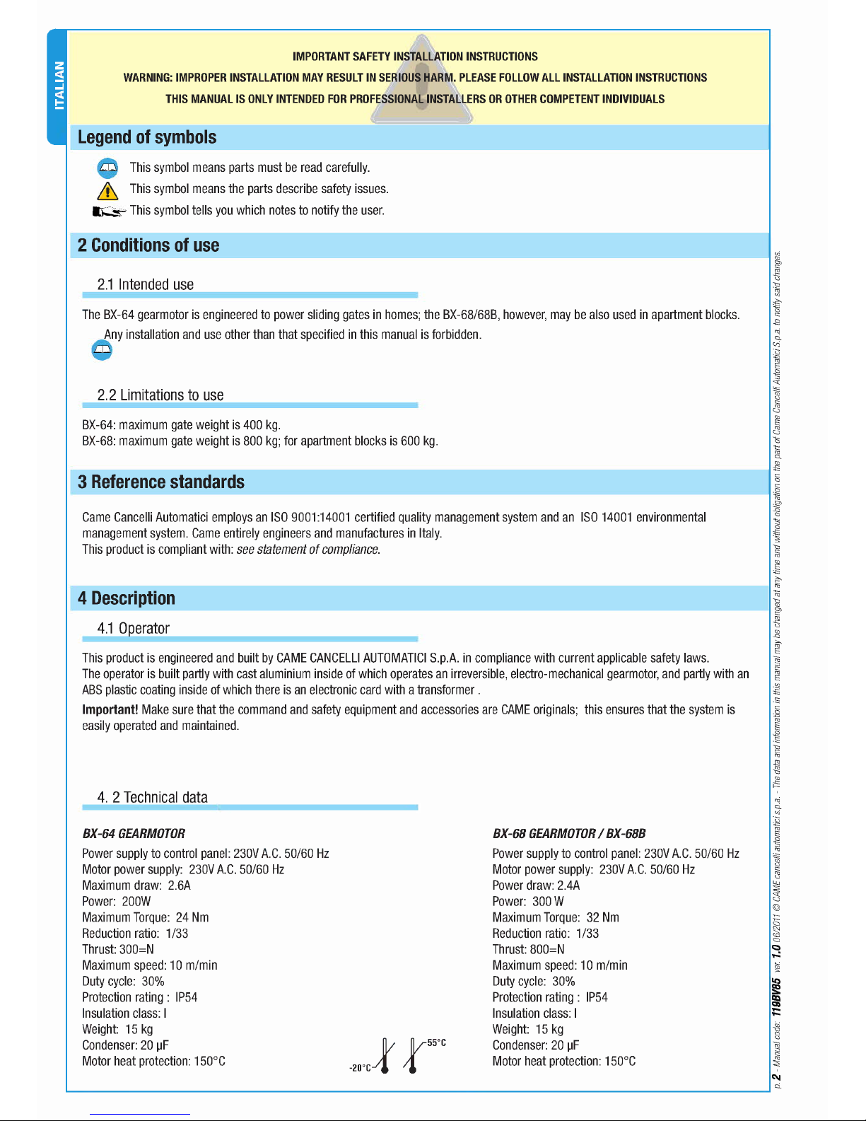
4. 2 Technical data
8X-64 GEARMOTOR
Power supply to control panel: 230V A.C. 50/60 Hz
Motor power supply: 230V A.C. 50/60 Hz
Maximum draw: 2.6A
Power: 200W
Maximum Torque: 24 Nm
Reduction ratio: 1/33
Thrust: 300=N
Maximum speed: 10 m/min
Duty cycle: 30%
Protection rating: IP54
Insulation class: I
Weight: 15 kg
Condenser: 20
IlF
Motor heat protection: 150°C
8X-68 GEARMOTOR / 8X-688
Power supply to control panel: 230V A.C. 50/60 Hz
Motor power supply: 230V A.C. 50/60 Hz
Power draw: 2.4A
Power: 300W
Maximum Torque: 32 Nm
Reduction ratio: 1/33
Thrust: SOO=N
Maximum speed: 10 m/min
Duty cycle: 30%
Protection rating: IP54
Insulation class: I
Weight: 15 kg
Condenser: 20
IlF
Motor heat protection: 150°C
C\I
~--------------------------------------------------------------------------------~Q
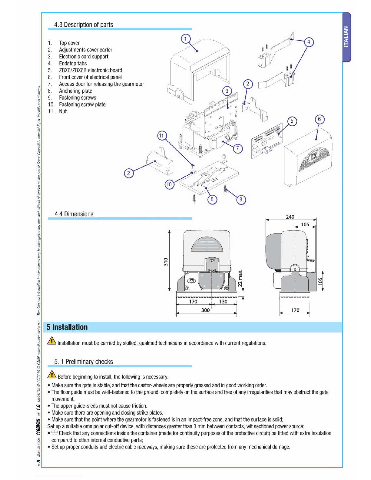
4.3 Description of parts
Top cover
Adjustments cover carter
Electronic card support
Endstop tabs
ZBX6/ZBX6B electronic board
1.
2.
3.
4.
5.
6. Front cover of electrical panel
7. Access door for releasing the gearmotor
8.
Anchoring plate
9.
Fastening screws
10.
Fastening screw plate
11.
Nut
4.4 Dimensions
240
o
,....
t'I'I
300
&
Installation must be carried by skilled, qualified technicians in accordance with current regulations.
5. 1 Preliminary checks
&
Before beginning to install, the following is necessary:
• Make sure the gate is stable, and that the castor-wheels are properly greased and in good working order.
• The floor guide must be well-fastened to the ground, completely on the surface and free of any irregularities that may obstruct the gate
movement.
• The upper guide-sleds must not cause friction.
• Make sure there are opening and closing strike plates.
• Make sure that the point where the gearmotor is fastened is in an impact-free zone, and that the surface is solid;
Set up a suitable omnipolar cut-off device, with distances greater than 3 mm between contacts, wit sectioned power source;
• ~ Check that any connections inside the container (made for continuity purposes of the protective circuit) be fitted with extra insulation
compared to other internal conductive parts;
• Set up proper conduits and electric cable raceways, making sure these are protected from any mechanical damage.
5.2 Tools and equipment
Make sure you have all the tools and materials needed to carry out the installation in total safety and in accordance with current
regulations. The figure shows some examples of the tools needed by installers.
5.3 Cable types and minimum thickness
Connection for Cable type
Cable length Cable length Cable length
1
< 10
m
10<20
m
20<30
m
230 V power source to control panel 3G x 1.5
mm-
3G x 2.5 mm
2
3G x 4
mm-
Flashing light
FROR GEl
2 x 0.5 mm
2
2 xl
mm-
2 x 1.5 mm
2
Photocell transmitters
20-22
2 x 0.5 mm
2
2 x 0.5 mm
2
2 x 0.5 mm
2
Photocell receivers
GEl EN
4 x 0.5 mm
2
4 x 0.5
mm-
4 x 0.5 mm
2
Accessories power source
50267-2-1
2 x 0.5 mm
2
2 x 0.5 mm
2
2 xl mm
2
Safety and command devices 2 x 0,5 mm
2
2 x 0.5 mm
2
2 x 0.5 mm
2
Antenna connection RG58 max. 10 m
N.B. If cables are of a different length than that shown in the table, determine the cable section based on the actual draw and the
number of connected devices and according the what is set forth in the GEl EN 60204-1 code of regulations.
For connections featuring several loads on the same line (i.e. sequential ones), the dimensions shown on the table must be reconsidered
according to the total draw and actual distances. When connecting products not featured in this manual, only refer to the literature
accompanying such products.
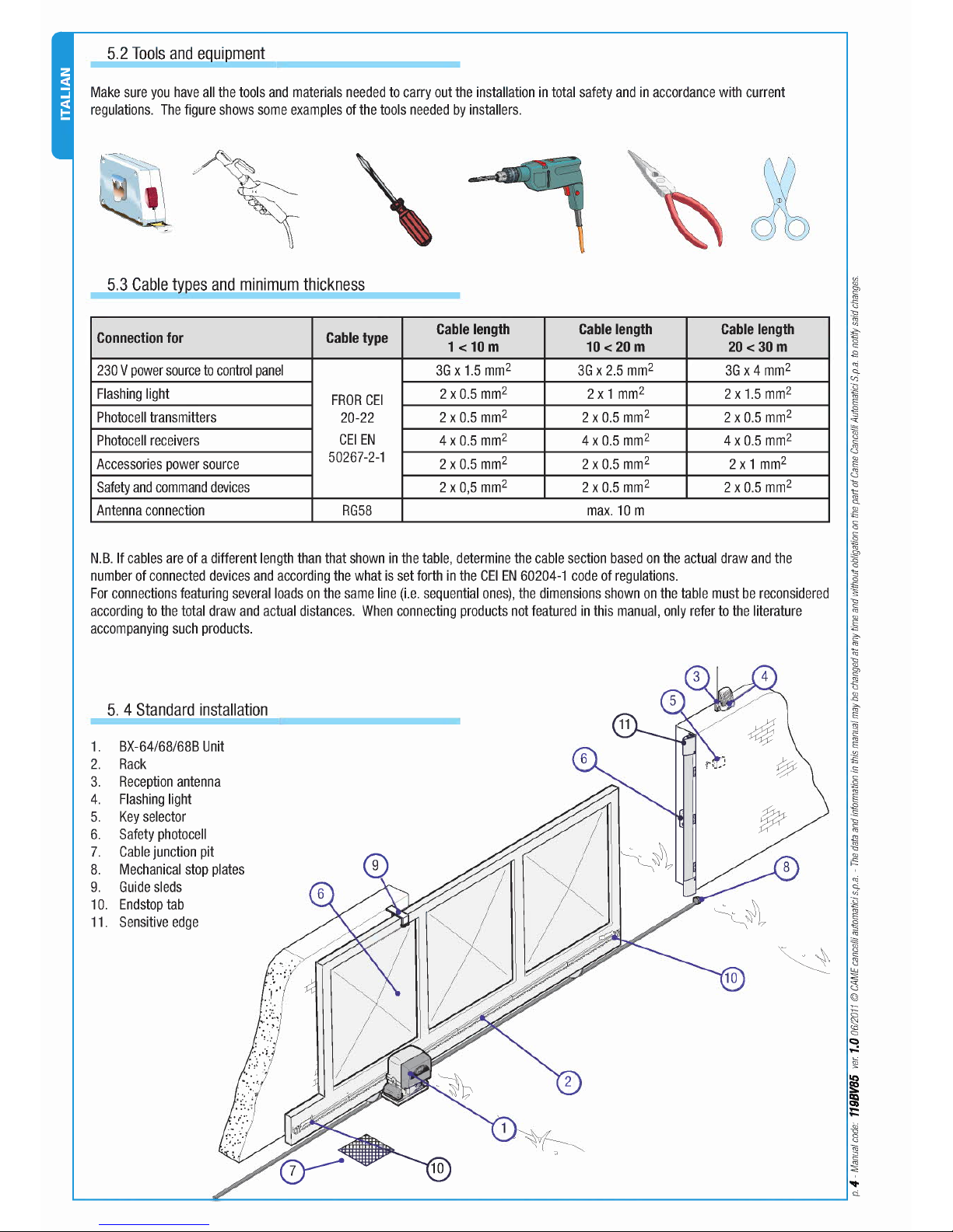
5. 4 Standard installation
1. BX-64/68/68B Unit
2. Rack
3. Reception antenna
4. Flashing light
5. Key selector
6. Safety photocell
7. Gable junction pit
8. Mechanical stop plates
9. Guide sleds
10. Endstop tab
11. Sensitive edge
~------------~~----------------------------------------------------------------~Q
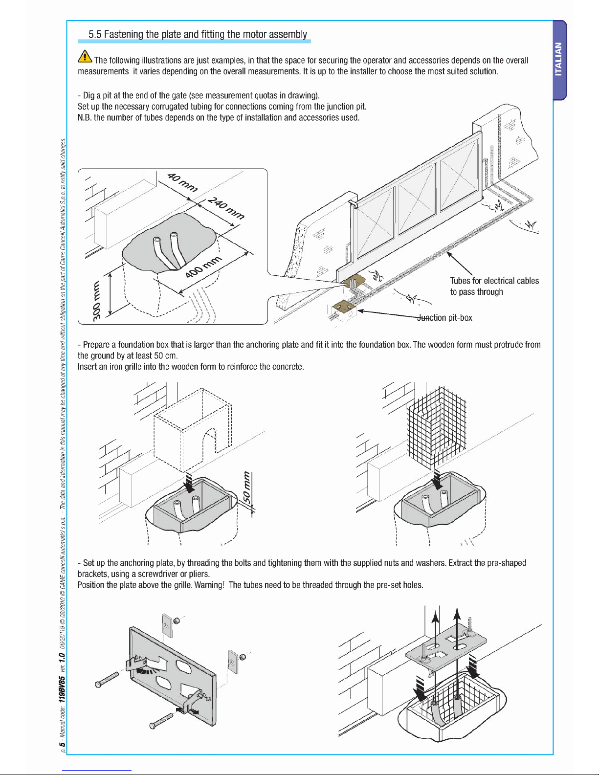
5.5 Fastening the plate and fitting the motor assembly
&
The following illustrations are just examples, in that the space for securing the operator and accessories depends on the overall
measurements it varies depending on the overall measurements. It is up to the installer to choose the most suited solution.
- Dig a pit at the end of the gate (see measurement quotas in drawing).
Set up the necessary corrugated tubing for connections coming from the junction pit.
N.B.the number of tubes depends on the type of installation and accessories used.
Tubesfor electrical cables
to pass through
dtiRction pit-box
- Prepare a foundation box that is larger than the anchoring plate and fit it into the foundation box.The wooden form must protrude from
the ground by at least 50 cm.
Insert an iron grille into the wooden form to reinforce the concrete.
- Set up the anchoring plate, by threading the bolts and tightening them with the supplied nuts and washers. Extract the pre-shaped
brackets, using a screwdriver or pliers.
Position the plate above the grille. Warning! The tubes need to be threaded through the pre-set holes.
 Loading...