

Page 1
119BV10IT
OPERATOR
FOR SLIDING GATES
Installation manual
BX-324 / BX-324V
English
E
N
Page 2
Page
2
2 - Manual code:
119BV10
119 B V10
ver.
2
2 10/2013
© CAME cancelli automatici s.p.a. - The data and information provided in this manual are subject to change at any time without prior notice by CAME Cancelli Automatici S.p.a.
Foreword
• This product should only be used for the purpose for which it was explicitly
designed. Any other use is considered dangerous. CAME Cancelli Automatici
S.p.A. is not liable for any damage resulting from improper, wrongful or unreasonable use • Keep these warnings with the installation and use manuals
issued with the automation system.
Before installing
(preliminary check: in case of a negative outcome, do not proceed until you
have complied with the safety requirements)
• Check that the part you intend to automate is in good mechanical condition,
balanced and aligned, and that it opens and closes properly. Make sure that
proper mechanical stops are already in place • If the operator will be installed
at a height of less than 2.5 m from the ground or other access level, check
whether you will need any protections and/or warnings • Any leaves fi tted
with pedestrian entrances onto which you will install an operator must have a
blocking mechanism when the leaf is in motion • Make sure that the opening
of the automated leaf is not an entrapment hazard as regards any surrounding
fi xed parts • Do not mount the operator upside down or onto any elements that
may fold under its weight. If needed, add suitable reinforcements at the points
where it is secured • Do not install onto leaves not on level ground • Check
that any lawn watering devices will not wet the operator from the bottom up.
Installation
• Carefully section o the entire site to prevent unauthorised access, especially by minors and children • Be careful when handling operators that weigh
more than 20 kg. In case, procure the tools required for safe gate movement
• All opening commands (buttons, key selectors, magnetic readers etc.) must
be installed at least 1.85 m from the perimeter of the area of turnstile movement, or where they cannot be reached from outside through the turnstile. In
addition, direct controls (button, touch sensitive keys, etc.) must be installed
at a height of at least 1.5 m and must not be accessible to the public • All
‘hold-to-run’ commands must be placed where the moving gate leaves, transit
areas and driveways are completely visible • If missing, apply a permanent
label that shows the position of the release mechanism • Before delivering to
the user, check that the system is EN 12453 (impact test) standard compliant.
Make sure that the operator has been properly adjusted and that the safety
and protection devices as well as the manual release are working properly •
Where necessary and in plain sight, apply the Warning Signs (e.g. gate plate)
Special instructions and advice for users
• Keep the gate’s area of operation clean and clear of any obstacles. Check
that there is no vegetation in the area of operation of the photocells and that
there are no obstacles in the area of operation of the operator • Do not allow
children to play with the fi xed command devices, or in the gate’s area of operation. Keep any remote control devices (i.e. transmitters) or any control devices away from children as well, to prevent the operator from being activated
accidentally •The operator is not designed to be used by persons (including
children) whose physical, sensorial or mental capacities are limited, or who are
lacking in experience or knowledge, unless said persons can be supervised
or given instructions regarding using the operator by a person responsible for
their safety • Frequently check the system, to see whether any anomalies or
signs of wear and tear appear on the moving parts, on the component parts, on
the securing points, on the cables and any accessible connections. Keep any
joints (i.e. hinges) lubricated and clean, and do the same where friction may
occur (i.e. slide rails) • Perform functional tests on photocells and sensitive
edges every six months. To check that the photocells work, pass an object in
front of them during closing. If the operator reverses the direction of movement
or comes to a halt, the photocells work correctly. This is the only maintenance
operation that must be carried out while the operator is live. Ensure that the
glass on the photocells is kept clean (use a cloth slightly moistened with water; do not use solvents or any other chemicals as these could damage the
devices) • If the system requires repairs or modifi cations, release the operator and do not use it until safety conditions have been restored • Cut o the
power supply before releasing the operator for manual openings and before
any other operation, to prevent dangerous situations. Read the instructions •
If the power cable is damaged, it must be replaced by the manufacturer or
the technical assistance service or by a person with a similar qualifi cation
so as to prevent any risks • It is STRICTLY FORBIDDEN for users to perform
OPERATIONS THEY ARE NOT EXPLICITLY REQUIRED AND ASKED to do in the
manuals. For repairs, adjustments and extraordinary maintenance, CONTACT
THE SPECIALIST TECHNICAL SERVICE CENTRE • On the periodic maintenance
log, note down the checks you have done.
Special instructions and advice for all
• Avoid working near the hinges or moving mechanical parts • Stay clear
of the gate’s area of operation when in motion • Do not resist the direction
of movement of the gate; this may present a safety hazard • At all times be
extremely careful about dangerous points that must be indicated by proper
pictograms and/or black and yellow stripes • When using a selector or command in ‘hold-to-run’ mode, keep checking that there are no people in the
area of operation of the moving parts. Do this until you release the command •
The gate may move at any time without warning • Always cut the power when
cleaning or performing maintenance.
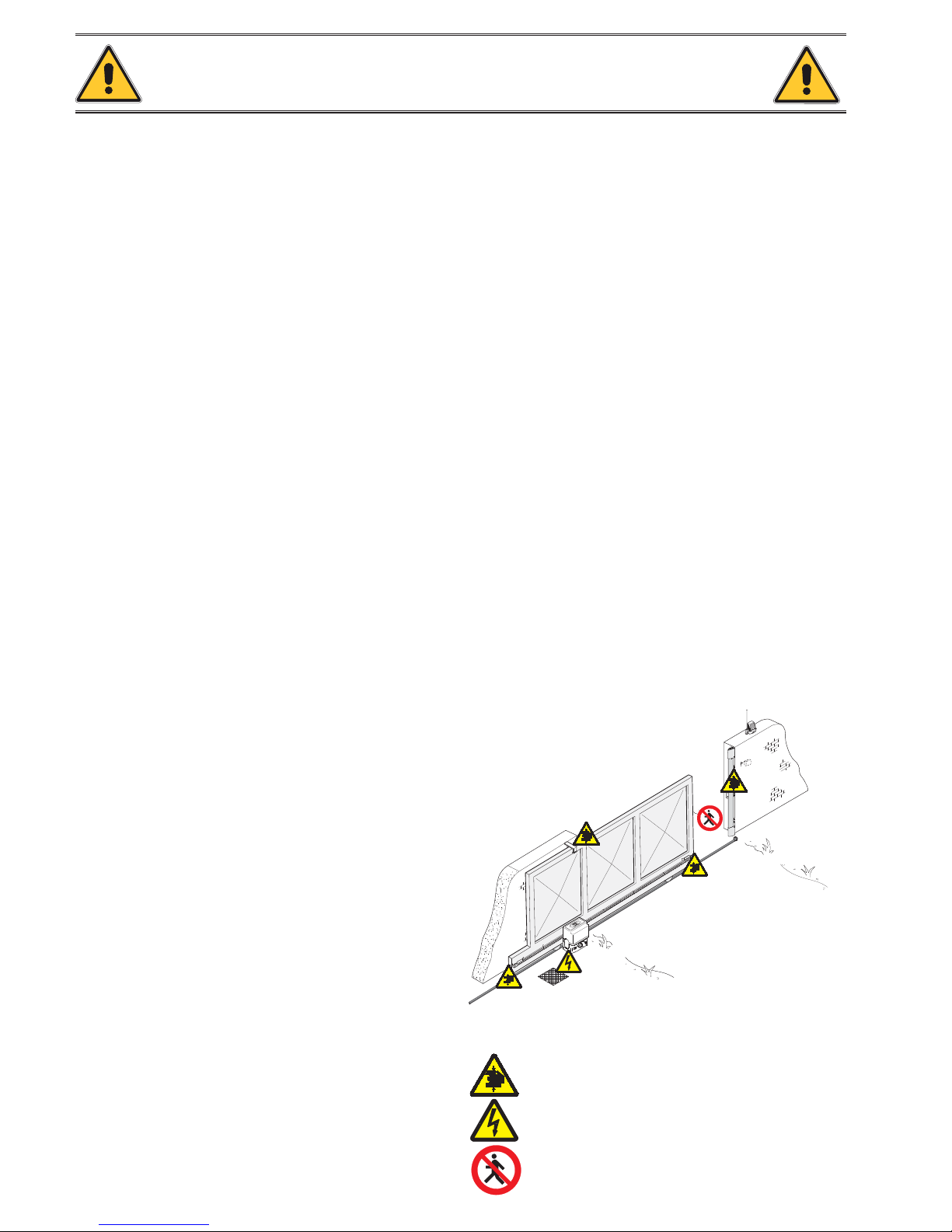
Danger of hand crushing
Danger - live parts
No transit during the manoeuvre
CAUTION!
important personal safety instructions:
READ CAREFULLY!
Page 3
Page
3
3 - Manual code:
119BV10
119 B V10
ver.
2
2 10/2013
© CAME cancelli automatici s.p.a. - The data and information provided in this manual are subject to change at any time without prior notice by CAME Cancelli Automatici S.p.a.
KEY
This symbol indicates parts to read carefully.
⚠
This symbol indicates parts about safety.
☞
This symbol tells you what to say to the end users.
DESCRIPTION
This product has been designed and built by CAME CANCELLI AUTOMATICI S.p.A. in compliance with applicable safety standards.
The operator consists of a cast aluminium part, with a non-reversible electromechanical gearmotor operating inside and an ABS container for the control board with
the transformer.
Intended use
The BX-324 / BX-324V operator has been designed to power sliding gates for residential and condominium use..
Any installation and operation that differs from what is set out in this manual is prohibited.
Limits of use
Type BX-324 / BX-324V
Max. leaf length (m) 8.5
Max. leaf weight (kg) 300
REGULATORY REFERENCES
Came Cancelli Automatici is a company with an ISO 9001-certified company quality management system and an ISO 14001-certified environmental management
system.
The product in question complies with the regulations referred to in the declaration of conformity.
Technical data
Type BX-324 - BX324V
Protection rating (IP) 54
P
ower supply (V - 50/60 Hz) 230
Motor power supply (V) 24
Power draw (A) 7
Power (W) 170
Thrust (N) 300
Opening speed (m/min) 12 - 17
Duty cycle (%) 50
Operating temperature (°C) -20 - +55
Gear ratio (i) 1/50
Insulation class
Weight (kg) 8 - 6
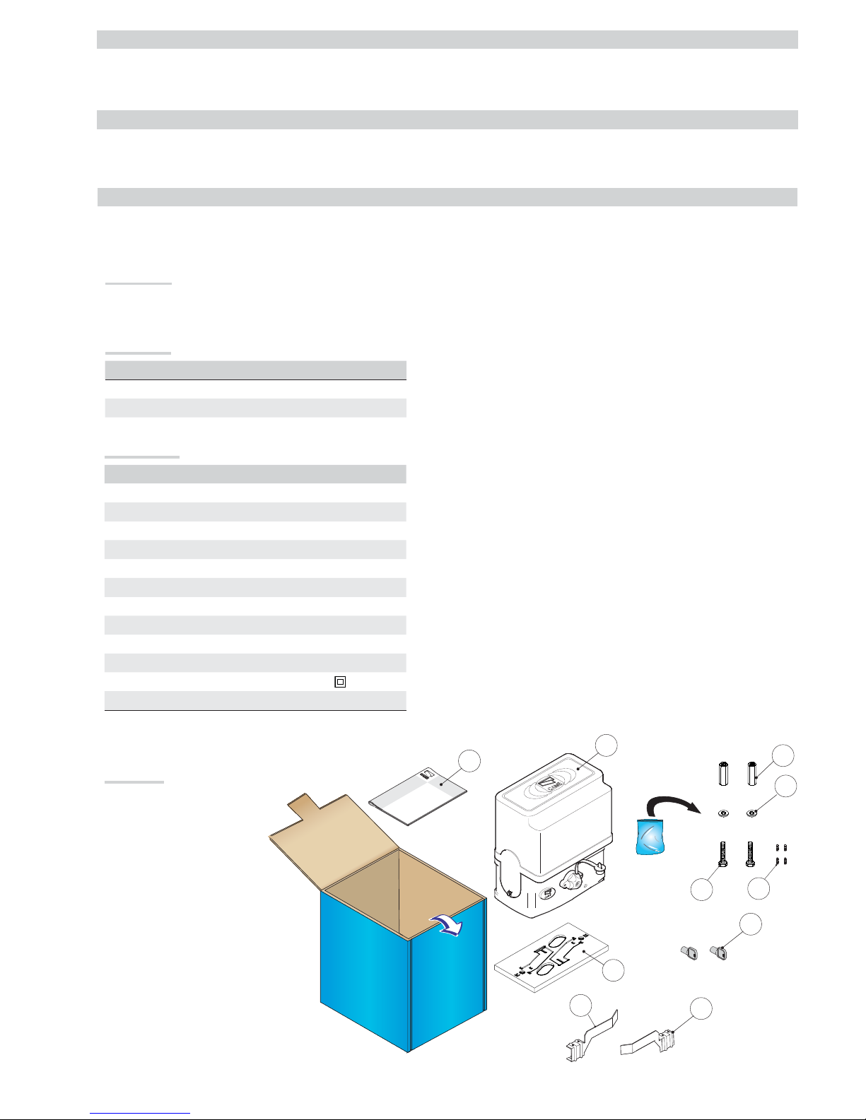
Packing list
1. 1 x Operator
2. 1 x Fixing plate
3. 1 x Installation manual
4. 2 x Nuts
5. 2 x Washers
6. 2 x Fixing screws
7. 2 x UNI5927 M6x25 end run grub
screws
8. 2 x Release keys
9. 1 x Left-hand end run fin
10. 1 x Right-hand end run fin
Page 4
CAME
XAM
Page
4
4 - Manual code:
119BV10
119 B V10
ver.
2
2 10/2013
© CAME cancelli automatici s.p.a. - The data and information provided in this manual are subject to change at any time without prior notice by CAME Cancelli Automatici S.p.a.
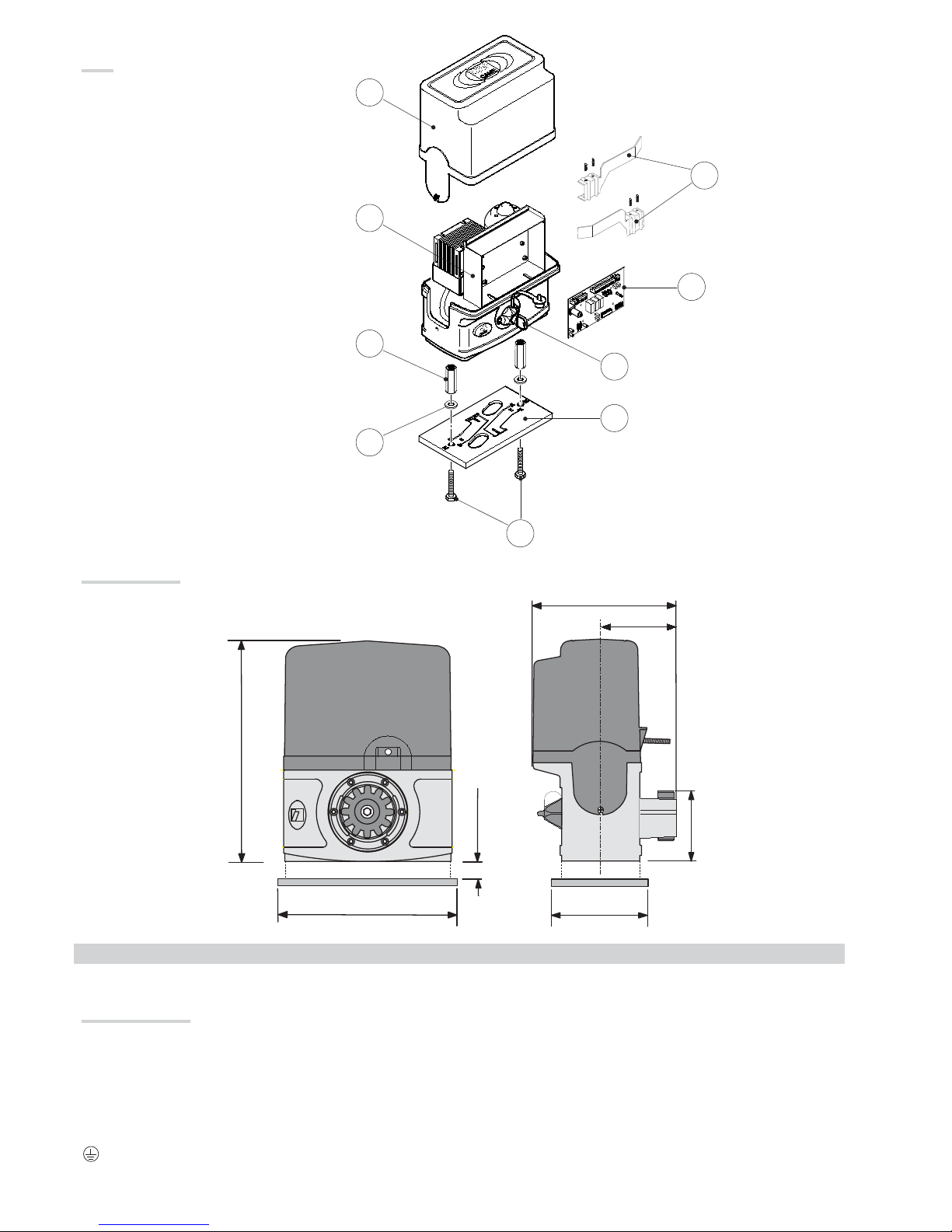
Dimensions (mm)
GENERAL INSTALLATION INSTRUCTIONS
⚠
Installation must be carried out by qualified and experien
ced personnel in compliance with applicable regulations.
Preliminary checks
⚠
Before installing the operator:
• Check that the gate is stable, and that the sliding wheels are in good condition and greased.
• Check that the ground guide is securely fixed to the ground, completely on the surface and free from irregularities that may hinder gate movement.
• Check that the upper guide blocks do not create friction.
• Make sure there is one opening and one closing mechanical stop.
• Make sure that the mounting point for the gearmotor is in an area protected from impacts and that the anchoring surface is solid;
• Provide a suitable single-pole disconnection device, with a maximum of 3 mm between the contacts, to disconnect the power supply;
•
Make sure that any connections within the container (made to ensure the continuity of the protection circuit) are fitted with additional insulation compared to
the other internal conductor parts;
• Prepare suitable piping and ducts for routing the electrical cables, ensuring protection against mechanical damage.
Description of the components
1. Cover
2. Control board mount
3. End run fins
4. Control board
5. Release key
6. Fixing plate
7. Fixing screws
8. Washer
9. Nut
Page 5
Page
5
5 - Manual code:
119BV10
119 B V10
ver.
2
2 10/2013
© CAME cancelli automatici s.p.a. - The data and information provided in this manual are subject to change at any time without prior notice by CAME Cancelli Automatici S.p.a.
Types of cables and minimum thicknesses
Connection Cable type
Cable length
1 < 10 m
Cable length
10 < 20 m
Cable length
20 < 30 m
Control panel power supply 230 V
FROR CEI
20-22
IEC EN
50267-2-1
3G x 1.5 mm
2
3G x 2.5 mm
2
3G x 4 mm
2
Flashing light 2 x 0.5 mm
2
2 x 1 mm
2
2 x 1.5 mm
2
Photocell transmitters 2 x 0.5 mm
2
2 x 0.5 mm
2
2 x 0.5 mm
2
Photocell receivers 4 x 0.5 mm
2
4 x 0.5 mm
2
4 x 0.5 mm
2
Control devices 2 x 0.5 mm
2
2 x 0.5 mm
2
2 x 0.5 mm
2
Antenna connection RG58 max. 10 m
N.B.: If the cables differ in length compared to what is shown in the table, the cable cross-section is determined according to the actual current draw of the devices
connected and according to the provisions of the IEC EN 60204-1 standard.
For connections that require several, sequential loads, the sizes given on the table must be re-evaluated based on actual power draw and distances. When
connecting products that are not specified in this manual, please refer to the documentation provided with said products.
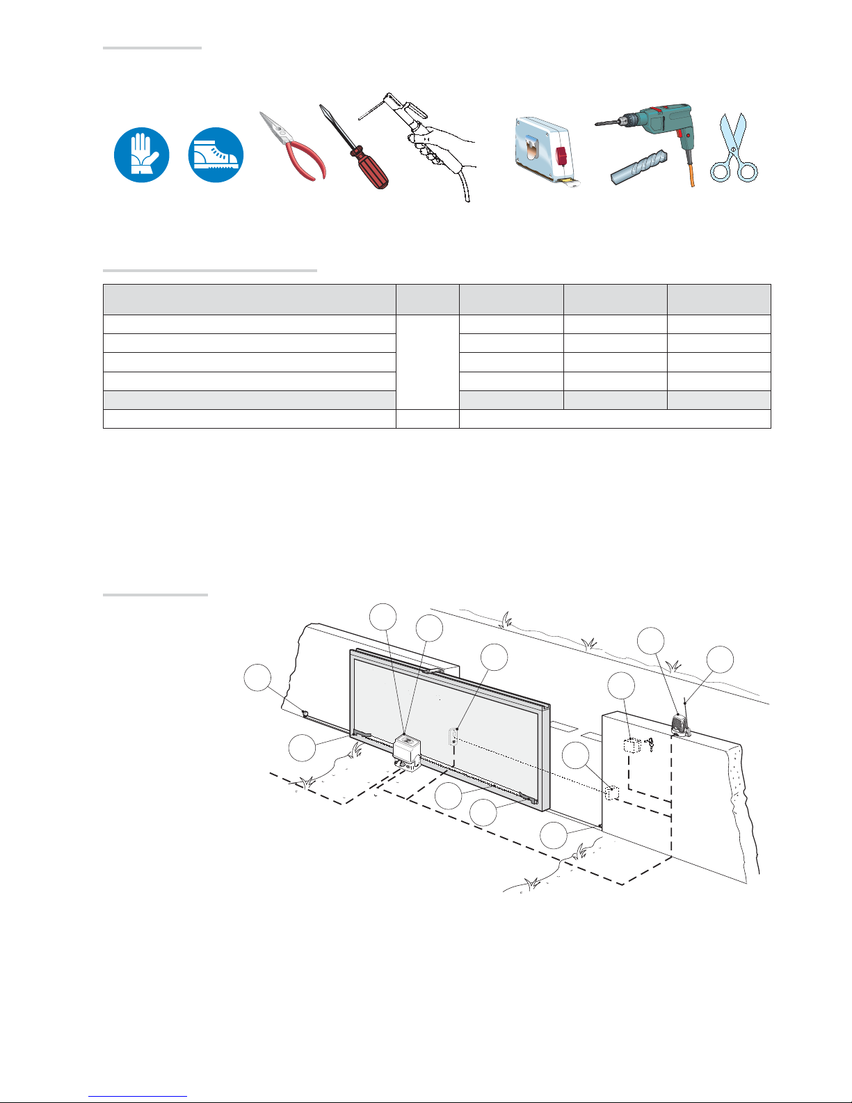
Tools and materials
Make sure you have all the tools and materials you will need for the installation at hand to work in total safety and compliance with current standards and
regulations. The figure shows some examples of installer’s tools.
Example of a system
1. Operator
2. Radio receiver
3. End run fins
4. Rack
5. Key selector
6. Flashing light
7. Antenna
8. Photocells
9. End run
Page 6

Page
6
6 - Manual code:
119BV10
119 B V10
ver.
2
2 10/2013
© CAME cancelli automatici s.p.a. - The data and information provided in this manual are subject to change at any time without prior notice by CAME Cancelli Automatici S.p.a.
INSTALLATION
⚠
The following illustrations are only examples, given that the spac
e for securing the operator and accessories varies depending on the overall dimensions. The
installation technician is responsible for choosing the most suitable solution.
Installing corrugated tubes
Make the hole for the counterframe.
Prepare the junction boxes and corrugated tubes necessary for the connections from the inspection chamber. In order
to connect the gearmotor, a Ø 60 mm corrugated tube is advisable. Ø 25 mm pipes are recommended for accessories,
on the other hand.
N.B. the number of tubes depends on the type of system installed and any accessories.
Installing the mounting plate
Prepare a counterframe that is larger than the mounting plate and place it in the hole. The counterframe must protrude 50 mm from ground level.
Insert an iron grid inside the counterframe to reinforce the concrete.
Secure the anchor brackets to the plate using the screws, nuts and washers supplied.
Position the mounting plate, respecting the measurements shown on the drawing, if the rack is already present.
Caution! The tube must pass through the prepared holes.
Page 7

24h
#!-%
#!-%
Page
7
7 - Manual code:
119BV10
119 B V10
ver.
2
2 10/2013
© CAME cancelli automatici s.p.a. - The data and information provided in this manual are subject to change at any time without prior notice by CAME Cancelli Automatici S.p.a.
Fill the counterframe with cement. The plate must be perfectly level with the screw threads completely on the surface.
Wait at least 24 hours for it to harden.
Remove the counterframe and fill the hole around the block of cement with earth.
Remove the nuts and washers from the screws.
Insert the electric cables in the tube until they protrude approximately 400 mm.
Securing the gearmotor
Remove the gearmotor cover by unscrewing the side screws. Position the gearmotor above the mounting plate.
Page 8

C
A
ME
#!-%
#!-%
CA
ME
Page
8
8 - Manual code:
119BV10
119 B V10
ver.
2
2 10/2013
© CAME cancelli automatici s.p.a. - The data and information provided in this manual are subject to change at any time without prior notice by CAME Cancelli Automatici S.p.a.
Unlock the gearmotor. Rest the rack on top of the gearmotor pinion.
Lift the gearmotor 5 to 10 mm up from the plate, using the threaded steel feet for any subsequent adjustments between the pinion and the rack.
Weld or secure the rack to the gate along its entire length.
To assemble the rack modules, use a piece of scrap and place it under the join point, securing it using two terminals.
N.B. if the rack is already present, proceed directly with adjusting the pinion/rack coupling distance.
Page 9

C
A
ME
#!-%
Page
9
9 - Manual code:
119BV10
119 B V10
ver.
2
2 10/2013
© CAME cancelli automatici s.p.a. - The data and information provided in this manual are subject to change at any time without prior notice by CAME Cancelli Automatici S.p.a.
Open and close the gate manually and adjust the pinion/rack coupling distance using the threaded feet (vertical adjustment) and the slots (horizontal adjustment).
This prevents the weight of the gate bearing upon the operator.
When adjustment is complete, secure the gearmotor to the plate using the washers and nuts.
Feet
Slot
Rack
Pinion
Rack
Pinion
Horizontal adjustment
Vertical adjustment
Determining the end run points
Position the end run fins on the rack and secure them using the 3 mm hex key. Their position limits the gate run.
N.B. ensure that the gate does not strike against the mechanical stop during opening or closing.
Left-hand end run fin
Right-hand end run fin
Page 10

01
%$77
/7 /7
( )& )$ )
/1
( &
$ % & '
8
10
1
2
3
4
5
679
01
(
+
-
/7 /7
/1
11
Page
10
10 - Manual code:
119BV10
119 B V10
ver.
2
2 10/2013
© CAME cancelli automatici s.p.a. - The data and information provided in this manual are subject to change at any time without prior notice by CAME Cancelli Automatici S.p.a.
ELECTRICAL CONNECTIONS
⚠
Caution! Before intervening on the control panel, disconnect mains power.
Control board power supply: 230 V AC, with 50-60 Hz frequency
Control device power supply: 24 VAC.
⚠
The total power of the accessories should not exceed 40 W.
T
he functions must be set using the dip switches and the adjustments using the trimmers.
All the connections are protected by quick fuses.
Description of the components
1. Power supply and gearmotor
con
nection terminal block
2. Line fuse
3. Accessory fuse
4. Panel fuse
5. Radio code memorisation
buttons
6. ACT trimmer: adjusting the
automatic closing time
7. Function select DIP
8. Connector for AF card
9. Indicator LED
10. Accessory, encoder and endrun connection terminal block
11. Emergency batteries connection
board terminal block.
FUSE TABLE
Line fuses 1.6 A-F
P
anel fuse 315 mA-F
Accessory fuse 1.6 A-F
General description
The card has an amperometric device that continuously monitors the engine thrust. When the gate encounters an obstacle, the amperometric sensor immediately
detects an overload in the drive and acts on gate movement by reversing its direction:
⚠
(1)
Caution: during closing, after 3 consecutive obstacles have been detected, the gate stops during opening and automatic closing is disabled. To resume
movement, press the command button or use the transmitter.
- reopens it when closing
(1)
- recloses it when opening (1)
Power supply
Terminals for power supply
of 24 V AC accessories.
230 VAC power supply
50/60 Hz frequency
Ring lug with screw and washer for
earthing
Page 11

1
(
( &
(
)& )$ )
01
(
COM
NC
COM
)& )$ )
01
(
COM
NC
NC
COM
NC
1
(
( &
Page
11
11 - M anual code:
119BV10
119 B V10
ver.
2
2 10/2013
© CAME cancelli automatici s.p.a. - The data and information provided in this manual are subject to change at any time without prior notice by CAME Cancelli Automatici S.p.a.
Connecting the gearmotor and end run
The motor is designed to be installed on the left, inside view.
If installing on the right, inside view, reverse the motor and end run terminals on the control panel.
Stop button (NC contact) Stops the gate with the exclusion of
automatic closing. T
o resume movement, press the control button
or other control device.
NB: if not used, short 1 and 2.
OPEN-STOP-CLOSE-STOP (sequential) function / OPEN-CLOSE
(step-by-step) from the control device (N.O. contact) See dip switch
2 function selection.
Control devices
Flashing light (Contact rated for:
24 V AC / DC - 25 W max.).
Flashes during gate opening and
closing.
Indicator and lighting devices
24 VDC motor
with encoder
Closing
microswitch
Orange
Orange
White
Red
White
Brown
Green
Red
Green
Opening
microswitch
White
Brown
Green
Red
Green
Orange
Orange
White
Red
Page 12

1
( &
1
( &
RX TX
ON
OFF
+A.C.T-
&
Page
12
12 - Manual code:
119BV10
119 B V10
ver.
2
2 10/2013
© CAME cancelli automatici s.p.a. - The data and information provided in this manual are subject to change at any time without prior notice by CAME Cancelli Automatici S.p.a.
C1 = Contact (N.C.) of reopening when closing.
Input for safety devices such as photocells, sensitive edges
and other devices compliant with the EN 12978 standard.
While the operator is closing, the opening of the contact
causes the reversal of the direction of movement until
completely open.
Safety devices
Photocells
DIR
Photocells
DELTA-S
Photocells
DELTA
1 ON - AUTOMATIC CLOSING function activated
2 ON - OPEN-STOP-CLOSE-STOP function from the transmitter and/or the button (2-7) activated
2 OFF - OPEN-CLOSE function from the transmitter and/or the button (2-7) activated
Selecting the functions
A.C.T. Trimmer - Adjustment of the AUTOMATIC CLOSING time: from a minimum of 1 second to a maximum of 120 seconds.
Adjustments
If C1 is not used, short 2
and C1.
Page 13

❶
❷
❸
❹
TOP
TAM
#!-%
❷
❶
Page
13
13 - Manual code:
119BV10
119 B V10
ver.
2
2 10/2013
© CAME cancelli automatici s.p.a. - The data and information provided in this manual are subject to change at any time without prior notice by CAME Cancelli Automatici S.p.a.
FINAL OPERATIONS
Securing the cover
After making the electrical connections and selecting
the functions and adjustments, insert the cover on the
gearmotor and secure it.
Connect the RG58 cable of the antenna
❶.
For the AF43S / AF43SM , radiofrequency cards only, position the jumper as shown according to the series of transmitters used❷.
DISCONNECT POWER AND REMOVE THE BATTERIES, IF PRESENT. Insert the AF card on the control board.
N.B. the control board only recognises the AF card when the operator is powered again ❸.
Hold down the CH1 key on the control board: the LED indicator flashes. Press a key on the transmitter to send the code. The LED will remain lit to indicate
that memorisation has taken place ❹.
CH1 = channel for direct control of a panel function (OPEN-CLOSE or OPEN-STOP-CLOSE-STOP, according to the selection made on DIP 2).
Activating the radio control
Contact rating: 5 A-24 V DC
Antenna
Control board
AF card
Indicator LED
Page 14

❶
❷
❸
Page
14
14 - Manual code:
119BV10
119 B V10
ver.
2
2 10/2013
© CAME cancelli automatici s.p.a. - The data and information provided in this manual are subject to change at any time without prior notice by CAME Cancelli Automatici S.p.a.
Releasing the gearmotor
⚠ The operation must be carried out while the power is o .
MAINTENANCE
☞
Before any maintenance, disconnect power to prevent any possible d
angerous situations that can be caused by accidental movement of the operator.
Lubricate the rotation points with grease whenever abnormal vibrations or squeaking occurs, as shown below.
Date Notes Signature
Periodic maintenance
Periodic maintenance log to be completed by the user (every six months)
RELEASING
L
OCKING
Page 15

Extraordinary maintenance log
Extraordinary maintenance
⚠
T
he table below is used to note any extraordinary maintenance, repairs or improvements carried out by
specialist companies.
⚠
Extraordinary maintenance must be carried out by specialist technicians.
DISMANTLING AND DISPOSAL
☞
CAME CANCELLI AUTOMATICI S.p.A. implements an UNI EN ISO 14001-certified and compliant Environmental Management System at its plant
s, to ensure
environmental protection.
Please continue our efforts to protect the environment, something that CAME considers to be one of the foundations in developing its business and market
strategies, simply by observing brief recommendations as regards disposal:
DISPOSAL OF PACKAGING
Packaging components (cardboard, plastic,etc.) can be disposed of together with normal household waste without any difficulty, by simply separating the different
types of waste and recycling them.
Before proceeding, it is always advisable to check specific regulations in force in the place of installation.
DISPOSE OF PROPERLY!
DISPOSAL OF THE PRODUCT
Our products are made with different materials. Most of them (aluminium, plastic, iron, electrical cables) can be disposed of together with normal household waste.
They can be recycled if collected, sorted and sent to authorised centres.
Other components (control boards, transmitter batteries etc.), on the other hand, may contain pollutants.
They should therefore be removed and handed over to companies authorised to recover and recycle them.
Before proceeding, it is always advisable to check specific regulations in force in the place of disposal.
DISPOSE OF PROPERLY!
DECLARATION OF CONFORMITY
Declaration - Came Cancelli Automatici S.p.A. declares that this device complies with the essential requirements and other relevant provisions established in
Directives 2006/42/CE and 2004/108/CE.
Reference code for requesting a true copy: DDI B IT B0 01
TROUBLESHOOTING
MALFUNCTIONS POSSIBLE CAUSES CHECKS AND REMEDIES
The gate does not open or
close
• No power
• The gearmotor is unlocked
• The transmitter battery is flat
• The transmitter is broken
• The stop button is stuck or broken.
• The opening/closing button or the key selector switch are stuck
• Photocells are in partial stop
• Check for mains power
• Lock the gearmotor
• Replace the batteries
• Contact service
• Contact service
• Contact service
• Contact service
The gate opens but does not
close
• The photocells are engaged
• Sensitive edge triggered
• Check that the photocells are clean and work
correctly
• Contact service
The gate closes but does not
open
• Sensitive edge triggered • Contact service
Installation technician stamp Operator name
Date of intervention
Technician signature
Customer signature
Intervention carried out _____________________________________________________________________________________
____________________________________________________________________________________________________
_______________________________________________________________________________________________
 Loading...