

Page 1
INSTALLATION MANUAL
BX-246
AUTOMATION
FOR SLIDING GATES
English
EN
119BU50EN
Page 2
Pag.
2
- Manual code:
119B U5 0
119 BU 50 ver.
2
04/2014 © CAME cancelli automatici s.p.a. - The data and information reported in this installation manual are susceptible to change at any time and without obligation on CAME cancelli automatici s.p.a. to notify users.
ENGLISH
Foreword
• This product should only be used for the purpose for which it was
explicitly designed. Any other use is considered dangerous. CAME Cancelli
Automatici S.p.A. is not liable for any damage resulting from improper,
wrongful or unreasonable use • Keep these warnings with the installation
and use manuals issued with the automation system.
Before installing
(preliminary check: in case of a negative outcome, do not proceed until you
have complied with the safety requirements)
• Check that the part you intend to automate is in good mechanical
condition, balanced and aligned, and that it opens and closes properly.
Make sure that proper mechanical stops are already in place • If the
operator will be installed at a height of less than 2.5 m from the ground
or other access level, check whether you will need any protections and/
or warnings • Any leaves fi tted with pedestrian entrances onto which you
will install an operator must have a blocking mechanism when the leaf is
in motion • Make sure that the opening of the automated leaf is not an
entrapment hazard as regards any surrounding fi xed parts • Do not mount
the operator upside down or onto any elements that may fold under its
weight. If needed, add suitable reinforcements at the points where it is
secured • Do not install onto leaves not on level ground • Check that any
lawn watering devices will not wet the operator from the bottom up.
Installation
• Carefully section o the entire site to prevent unauthorised access,
especially by minors and children • Be careful when handling operators
that weigh more than 20 kg. In case, procure the tools required for safe
gate movement • All opening commands (buttons, key selectors, magnetic
readers etc.) must be installed at least 1.85 m from the perimeter of the
area of turnstile movement, or where they cannot be reached from outside
through the turnstile. In addition, direct controls (button, touch sensitive
keys, etc.) must be installed at a height of at least 1.5 m and must not
be accessible to the public • All ‘hold-to-run’ commands must be placed
where the moving gate leaves, transit areas and driveways are completely
visible • If missing, apply a permanent label that shows the position of the
release mechanism • Before delivering to the user, check that the system
is EN 12453 (impact test) standard compliant. Make sure that the operator
has been properly adjusted and that the safety and protection devices as
well as the manual release are working properly • Where necessary and in
plain sight, apply the Warning Signs (e.g. gate plate)
Special instructions and advice for users
• Keep the gate’s area of operation clean and clear of any obstacles. Check
that there is no vegetation in the area of operation of the photocells and
that there are no obstacles in the area of operation of the operator • Do
not allow children to play with the fi xed command devices, or in the gate’s
area of operation. Keep any remote control devices (i.e. transmitters) or any
control devices away from children as well, to prevent the operator from
being activated accidentally •The operator is not designed to be used by
persons (including children) whose physical, sensorial or mental capacities
are limited, or who are lacking in experience or knowledge, unless said
persons can be supervised or given instructions regarding using the
operator by a person responsible for their safety • Frequently check the
system, to see whether any anomalies or signs of wear and tear appear
on the moving parts, on the component parts, on the securing points, on
the cables and any accessible connections. Keep any joints (i.e. hinges)
lubricated and clean, and do the same where friction may occur (i.e. slide
rails) • Perform functional tests on photocells and sensitive edges every
six months. To check that the photocells work, pass an object in front of
them during closing. If the operator reverses the direction of movement or
comes to a halt, the photocells work correctly. This is the only maintenance
operation that must be carried out while the operator is live. Ensure that the
glass on the photocells is kept clean (use a cloth slightly moistened with
water; do not use solvents or any other chemicals as these could damage
the devices) • If the system requires repairs or modifi cations, release the
operator and do not use it until safety conditions have been restored • Cut
o the power supply before releasing the operator for manual openings
and before any other operation, to prevent dangerous situations. Read the
instructions • If the power cable is damaged, it must be replaced by the
manufacturer or the technical assistance service or by a person with a
similar qualifi cation so as to prevent any risks • It is STRICTLY FORBIDDEN
for users to perform OPERATIONS THEY ARE NOT EXPLICITLY REQUIRED
AND ASKED to do in the manuals. For repairs, adjustments and extraordinary
maintenance, CONTACT THE SPECIALIST TECHNICAL SERVICE CENTRE •
On the periodic maintenance log, note down the checks you have done.
Special instructions and advice for all
• Avoid working near the hinges or moving mechanical parts • Stay clear
of the gate’s area of operation when in motion • Do not resist the direction
of movement of the gate; this may present a safety hazard • At all times
be extremely careful about dangerous points that must be indicated by
proper pictograms and/or black and yellow stripes • When using a selector
or command in ‘hold-to-run’ mode, keep checking that there are no people
in the area of operation of the moving parts. Do this until you release the
command • The gate may move at any time without warning • Always cut
the power when cleaning or performing maintenance.
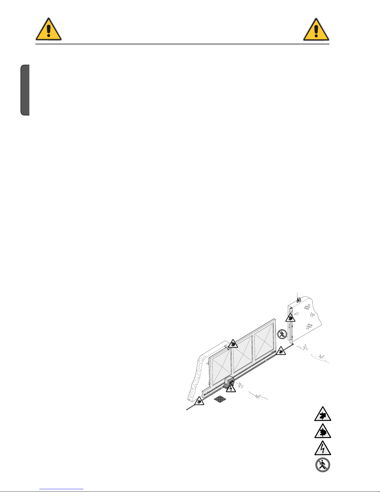
Danger of hand crushing
Danger - live parts
No transit during the manoeuvre
CAUTION!
important personal safety instructions:
READ CAREFULLY!
Danger of crushing feet
Page 3

#
#
Pag.
3
-
Manual code
:
119B U5 0
119 BU 50 ver.
2
04/2014
© CAME cancelli automatici s.p.a. -
The data and information reported in this installation manual are susceptible to change at any time and without obligation on CAME cancelli automatici s.p.a. to notify users.
ENGLISH
4.1 Operator
4 Description
2.1 Intended use
1 Legend of symbols
This symbol tells you to read the section with particular care.
This symbol tells you that the sections concern safety issues.
This symbol tells you what to say to the end-users.
2 Conditions of use
The BX246 operator is designed to power sliding gates in residential and condominium settings.
Do not install or use unless as otherwise shown in this manual.
3 Reference standards
“IMPORTANT INSTALLATION, SAFETY INSTRUCTIONS”
“CAUTION: IMPROPER INSTALLATION MAY CAUSE SERIOUS DAMAGE, FOLLOW ALL INSTALLATION INSTRUCTIONS CAREFULLY”
“THIS MANUAL IS ONLY FOR PROFESSIONAL OR QUALIFIED INSTALLERS”
2.2 Limitations to use
This product is engineered and manufactured by CAME CANCELLI AUTOMATICI S.p.A. in compliance with current safety standards.
The operator is made of a cast aluminium part inside of which operates the irreversible, electromechanical gearmotor and an ABS plastic
lining which holds the electronic card, transformer and the clamp to house 2 emergency batteries.
4.2 Technical features
The company CAME cancelli automatici is ISO 9001 quality certified; it has also obtained the ISO 14001 environmental safeguarding
certification. CAME engineers and manufactures all of its products in Italy.
This product complies with the following legislation: see declaration of compliance.
For intensive or condominium use: max gate weight 600kg with max gate length 18 m.
BX246 OPERATOR
Control panel power supply: 230V AC 50/60Hz
Operator power supply: 24V DC
Draw: 10 A
Power: 400 W
Reduction ratio: 1/33
Thrust: 700 N
Max speed.: 6÷12 m/min
Duty cycle: intensive use
Protection rating: IP54
Insulation class: I
Weight: 15 kg
Page 4
9
3
4
2
5
6
7
10
11
1
2
8
Pag.
4
- Manual code:
119B U5 0
119 BU 50 ver.
2
04/2014 © CAME cancelli automatici s.p.a. - The data and information reported in this installation manual are susceptible to change at any time and without obligation on CAME cancelli automatici s.p.a. to notify users.
ENGLISH
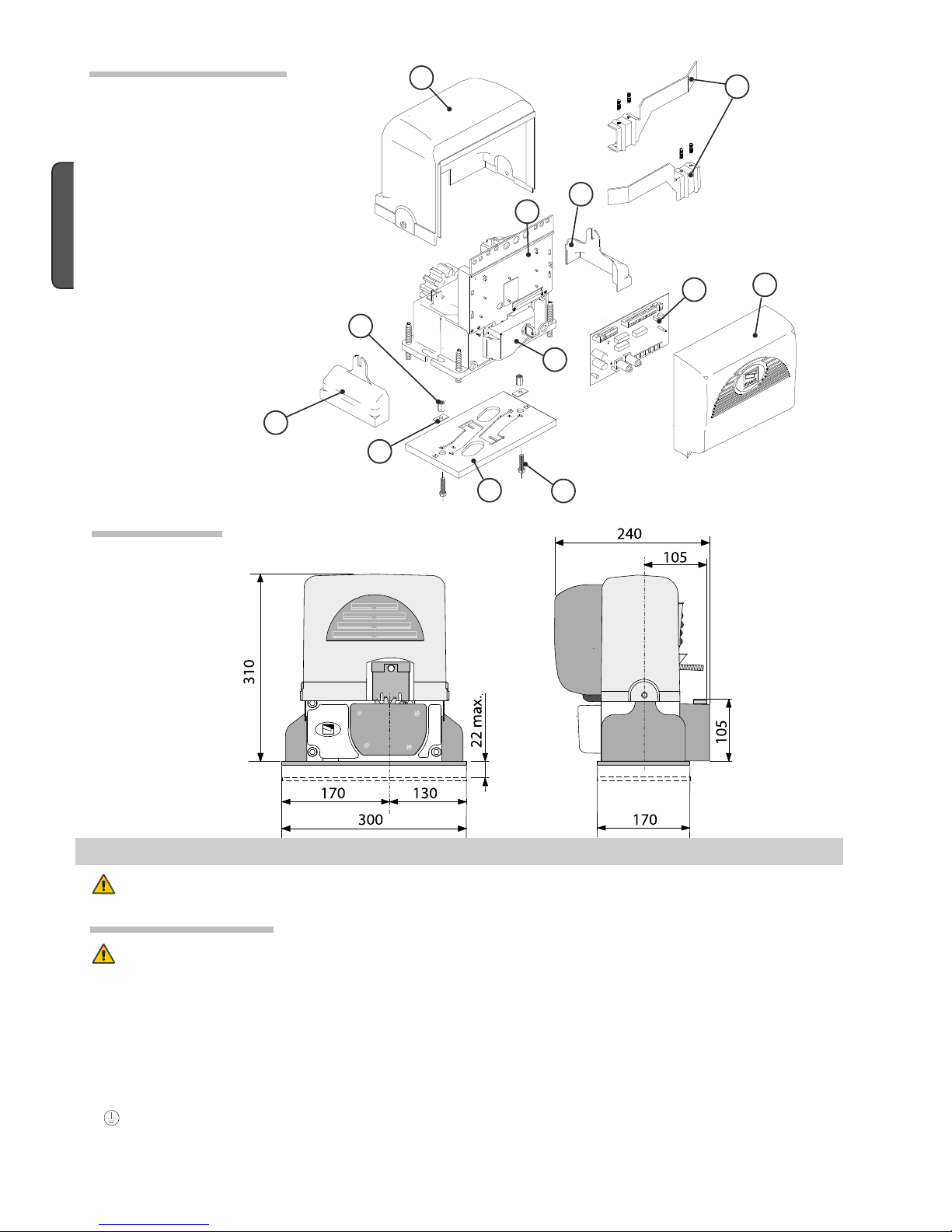
4.4 Dimensions
4.3 Description of parts
5 Installation
Installation must be carried out by expert qualified personnel and in full compliance with current regulations.
5.1 Preliminary checks
Before installing, do the following:
• Make sure that the gate is stable, and that the castors are in good working order and properly greased.
• The ground rack must be well secured to the ground, entirely above the surface and free of any irregularities that may obstruct the
gate’s movement.
• The upper guide rails must not create any friction.
• Make sure that there is a closing and an opening endstops.
• Make sure that the operator is attached to a solid surface and protected from any impacts;
• Make sure you have a suitable omnipolar cut-off device with contacts more than 3 mm apart, and independent (sectioned off) power
supply;
• Check that any connections inside the container (that provide continuity to the safety circuit) are fitted with additional insulation
compared to other internal live parts;
• Make sure you have suitable tubing and conduits for the electrical cables to pass through and be protected against mechanical
damage.
1 - Top cover
2 - Settings casing
3 - Control board support
4 - Endstop fins
5 - ZD2 electronic card
6 - Front cover to control panel
7 - Gearmotor release door
8 - Securing plate
9 - Securing bolt
10 - Securing screw plate
11 - Nut
Page 5
3
1
8
2
6
6
7
9
10
10
4
5
11
Pag.
5
-
Manual code
:
119B U5 0
119 BU 50 ver.
2
04/2014
© CAME cancelli automatici s.p.a. -
The data and information reported in this installation manual are susceptible to change at any time and without obligation on CAME cancelli automatici s.p.a. to notify users.
ENGLISH
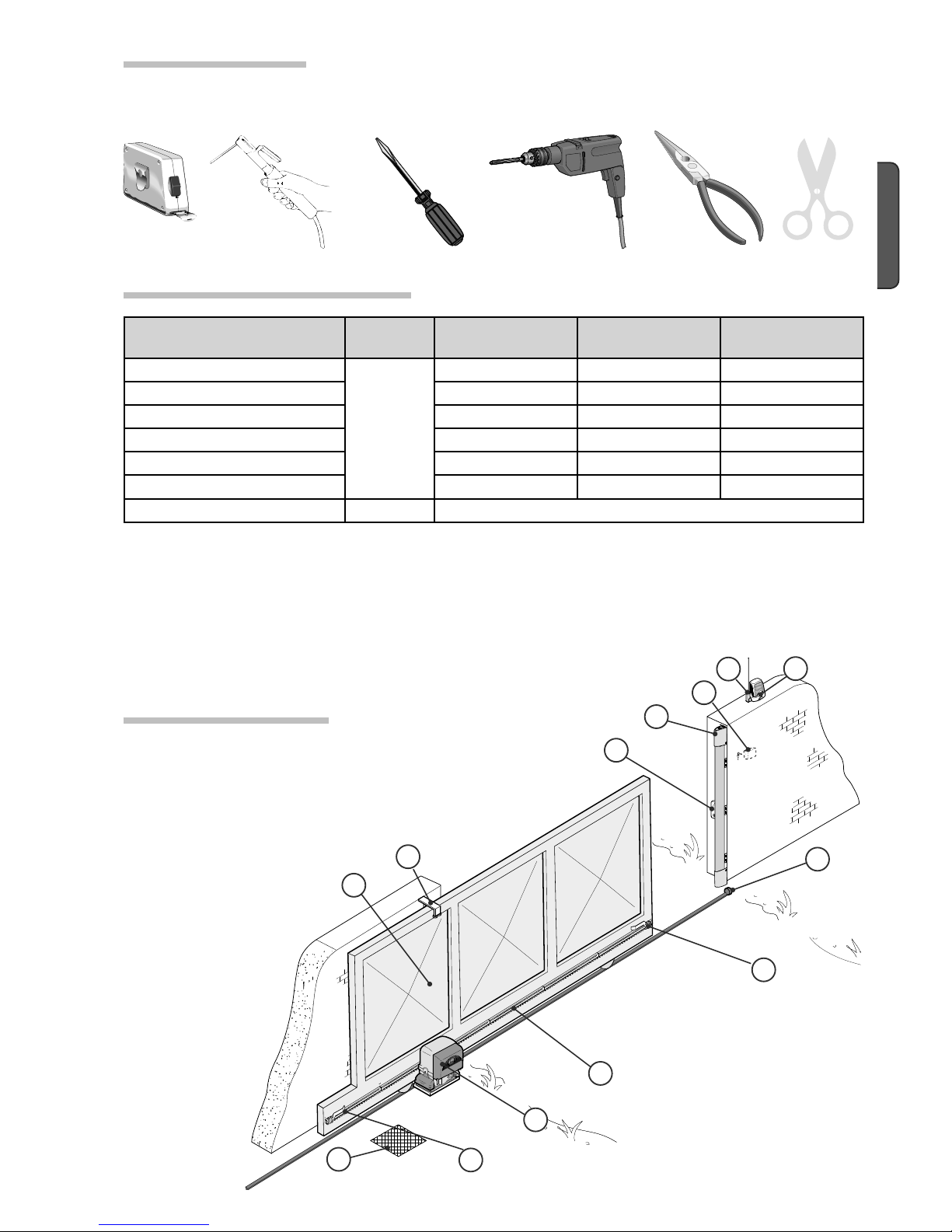
Make sure you have all the tools and materials you will need for the installation at hand to work in total safety and compliance with the
current standards and regulations. The following figure illustrates the minimum equipment needed by the installer.
N.B.: If the cable length differs from that specified in the table, then you must determine the proper cable diameter in the basis of the
actual power draw by the connected devices and depending on the standards specified in CEI EN 60204-1.
For connections that require several, sequential loads, the sizes given on the table must be re-evaluated based on actual power draw
and distances. When connecting products that are not specified in this manual, please follow the documentation provided with said
products.
5.3 Cable list and minimum thickness
Connection Type of cable
Length of cable
1 < 10 m
Length of cable
10 < 20 m
Length of cable
20 < 30 m
Control panel power supply 230V
FROR CEI
20-22
CEI EN
50267-2-1
3G x 1,5 mm
2
3G x 2,5 mm
2
3G x 4 mm
2
Flashing light 2 x 0,5 mm
2
2 x 1 mm
2
2 x 1,5 mm
2
Photocell transmitter 2 x 0,5 mm
2
2 x 0.5 mm
2
2 x 0,5 mm
2
Photocell receiver 4 x 0,5 mm
2
4 x 0,5 mm
2
4 x 0,5 mm
2
Accessories power supply 2 x 0,5 mm
2
2 x 0,5 mm
2
2 x 1 mm
2
Safety and control devices 2 x 0,5 mm
2
2 x 0,5 mm
2
2 x 0,5 mm
2
Antenna connection RG58 max. 10 m
5.2 Tools and materials
1) BX246 assembly
2) Rack
3) Reception Antenna
4) Flashing light
5) Keyswitch selector
6) Safety photocells
7) Electric cable junction box
8) Mechanical endstops
9) Guide rails
10) Endstop fi ns
11) Sensitive edge
5.4 Standard installation
Page 6
Pag.
6
- Manual code:
119B U5 0
119 BU 50 ver.
2
04/2014 © CAME cancelli automatici s.p.a. - The data and information reported in this installation manual are susceptible to change at any time and without obligation on CAME cancelli automatici s.p.a. to notify users.
ENGLISH
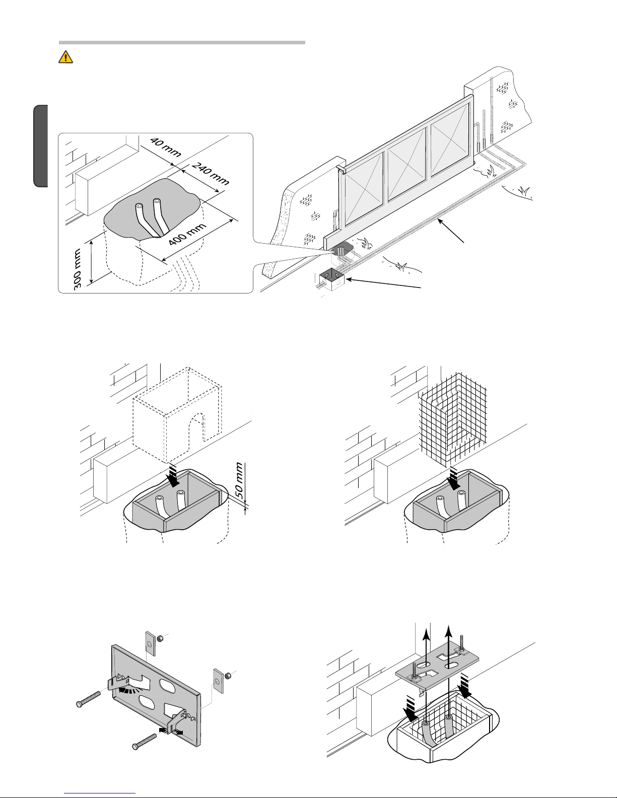
- Dig a pit to the side of the gate (see measurements from diagram).
Prepare the corrugated tubes you will need when making connections coming from the shunt pit.
N.B. the number of tubes depends on the type of system and the accessories you will hook up.
The following applications are only examples, as the space for installing the ratiomotor and accessories varies according to
obstructions. It is thus up to the system installer to select the most suitable solution.
Shunt pit
5.5 Securing the plate and installing the assembly
Conduits for electric
cables
- Prepare the securing plate, insert the bolts into the holes and lock them using the supplied nuts and washers. Extract the preformed
brackets using a screw driver or a set of pliers.
- Position the plate on top of the grid. Careful! The tubes need to pass through the apposite holes.
- Prepare a form box that is larger in size than the securing plate and insert it into the pit. The form box should jut 50mm above ground
level.
Insert an iron grid inside the from box to reinforce the concrete.
Page 7
H
Pag.
7
-
Manual code
:
119B U5 0
119 BU 50 ver.
2
04/2014
© CAME cancelli automatici s.p.a. -
The data and information reported in this installation manual are susceptible to change at any time and without obligation on CAME cancelli automatici s.p.a. to notify users.
ENGLISH
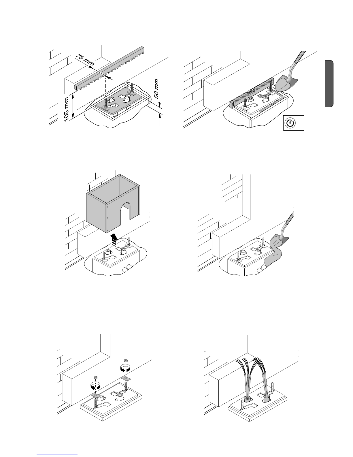
- To position the plate in relation to the rack please see the measurements on the diagram.
Fill the form box with cement and wait for at least 24 hours for it to solidify.
- Remove the form box, fi ll the pit around the cement block with soil.
- Unbolt the nuts and washers from the bolts. The securing plate must be clean, perfectly aligned and with the bolt threads completely
on the surface.
Insert the electric cables into the tubes until they exit about 400mm.
Page 8
Pag.
8
- Manual code:
119B U5 0
119 BU 50 ver.
2
04/2014 © CAME cancelli automatici s.p.a. - The data and information reported in this installation manual are susceptible to change at any time and without obligation on CAME cancelli automatici s.p.a. to notify users.
ENGLISH
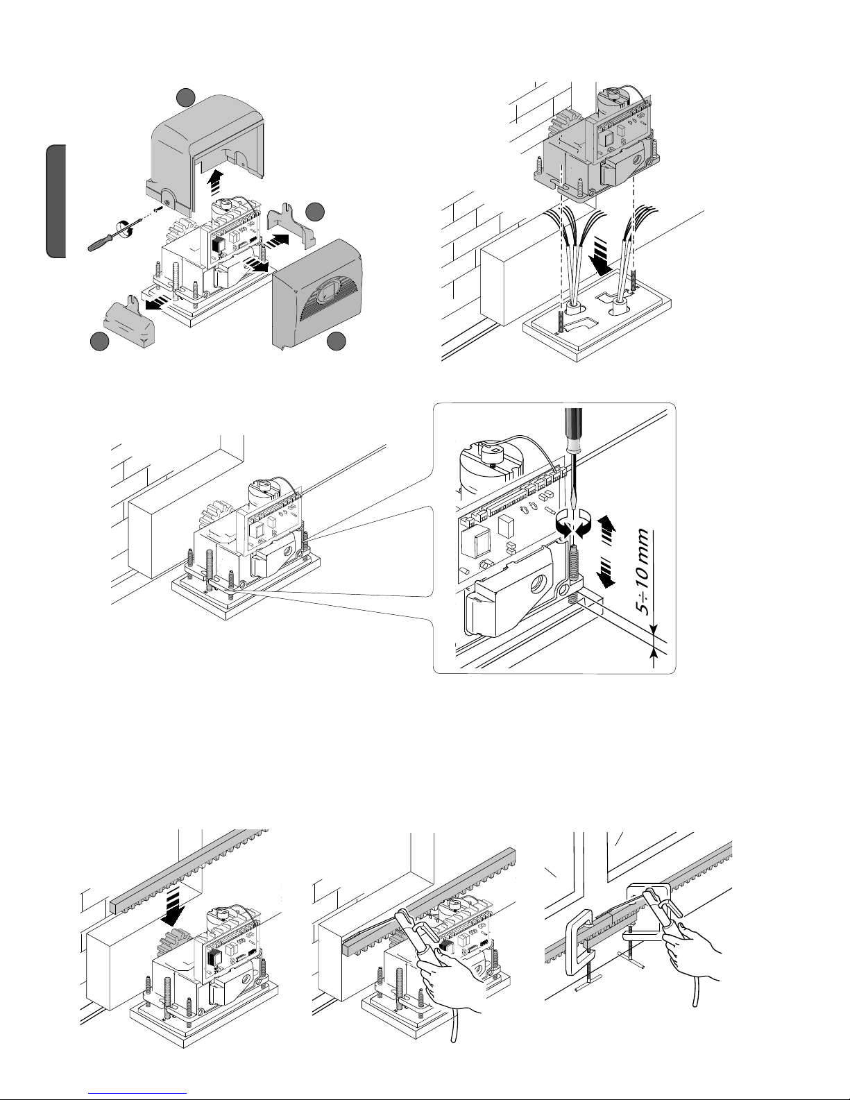
- Remove the cover from the gearmotor by loosening the side bolts, perforate the cable shafts using a screwdriver or a pair of scissors
and position the gearmotor atop the plate. Careful! The electric cables must pass through the cable shafts.
- Lift the gearmotor from the securing plate by about 5 to 10mm by using the threaded steel-levelling feet to allow any later adjustments
between the pinion and the rack.
- The following illustrations for the securing the rack, are just examples of applications. It is up to the installer to choose the best
solution.
Releasing the gearmotor (see paragraph on manual release). Rest the rack on the gearmotor pinion.
Weld or secure the rack to the gate along its entire length.
To assemble the rack modules, use an excess piece of rack and place it under the joining point, then block it using two C-clamps.
Note: if a rack is already in place, then just adjust the pinion-to-rack distance.
Page 9

Pag.
9
-
Manual code
:
119B U5 0
119 BU 50 ver.
2
04/2014
© CAME cancelli automatici s.p.a. -
The data and information reported in this installation manual are susceptible to change at any time and without obligation on CAME cancelli automatici s.p.a. to notify users.
ENGLISH
- Open and close the gate manually and register the pinion-to-rack distance using the threaded steel-levelling feet (for vertical
adjusting) and the slotted holes (horizontal adjusting). This prevents the weight of the gate from bearing on the operator.
Once adjustments are fi nished, secure the assembly using the nuts and washers.
Insert the cover after performing the adjustments and settings on the electronic card.
Levelling feet
Slotted holes
Rack
Pinion
vertical adjusting
horizontal adjusting
Rack
Pinion
Page 10

Pag.
10
10 - Manual code:
119B U5 0
119 BU 50 ver.
2
04/2014 © CAME cancelli automatici s.p.a. - The data and information reported in this installation manual are susceptible to change at any time and without obligation on CAME cancelli automatici s.p.a. to notify users.
ENGLISH
5.7 Manually releasing the gearmotor
- Insert the trilobed key into the lock, push it in and turn it clockwise ....
5.6 Mounting the endstop fins
Place the endstop fi ns onto the rack and secure them using a 3 mm Allen wrench. Their positioning limits the gate run.
Note: the gate schould not slam against the mechanical stop, when opening or closing.
Mechanical stop
WARNING: opening the door will
disengage the motor (i.e. it will not
function).
To operate the motor the release
mechanism must be fi rmly fastened.
Trilobed key
Knob
..... open the small door and turn the release handle clockwise.
Page 11

Pag.
11
11 -
Manual code
:
119B U5 0
119 BU 50 ver.
2
04/2014
© CAME cancelli automatici s.p.a. -
The data and information reported in this installation manual are susceptible to change at any time and without obligation on CAME cancelli automatici s.p.a. to notify users.
ENGLISH
6 Control board
6.1 General description
FUSE TABLE ZD2
To protect: fuse:
Motor 10 A-F
Control board (line) 1,6 A-F
Accessories 1.6 A-F
Command devices 3,15 mA-F
6.2 Main components
1) Power supply terminals
2) Endstop terminals
3) Motor terminals
4) Encoder terminals
5) Accessory fuse
6) Card fuse
7) Button for memorising the radio code
8) Radio-code signalling LED indicator
9) 230V-power signalling LED
10) Control and signalling LED group
11) Function selector DIP switch
12) Socket for connecting the remote control’s radiofrequency
card
13) Antenna terminal
14) Accessories’ and command device’s terminals
15) Motor fuse
16) Line fuse
17) Setting trimmer
18) Battery charger (LBD2) connecting terminal boards
19) Transformer-connecting terminal board
Use 230V AC to power the electronic card using the L-N
terminals, at a max 50/60Hz frequency.
Use 24V to power the command devices and accessories.
Careful! The accessories cannot exceed 37W of overall power.
The card is fi tted with an amperometric device which constantly
monitors the motor’s drive. When the gate runs into an obstacle,
the amperometric sensor immediately detects the overload on
the drive and so inverts the gate’s movement:
- opens it if it is closing
- closes it if it is opening
Warning: after 3 obstacle detections, the gate stops when in
opening-mode and excludes automatic-closing mode; to regain
movement press the command button or use the remote control.
All connections are protected by quick-fuses – see table.
The card handles the following functions:
- Automatic closing after an opening command;
- Warning light pre-fl ashing;
- Obstacle detection when gate is still at any point;
- Constant monitoring of photocell operations.
- Opening/closing;
- Opening/closing in maintained action mode;
- partial opening;
- total stop.
Apposite trimmers regulate:
- The automatic closing’s running time;
- The partial opening;
- The amperometric device’s detection sensitivity, in both normal
and brake modes;
- the speed of both the normal gate run and the brake mode run.
Warning! Before acting on the machinery, cut o the main power
supply and disconnect any emergency batteries.
TECHNICAL INFORMATION
Power supply 230V - 50/60 Hz
Maximum power allowed 400 W
Absorption at rest 100 mA
Maximum power for 24V accessories 35 W
Insulation rating II
Page 12

ON
2
1345678910
13
16
4
17
5
6
7
12
10
18
8
9
3
14
2
1
14
15
19
-.
%$&#&!&
-.
%$&#&!&
COM
NC
NC
COM
COM
NC
NC
COM
11
Pag.
12
12 - Manual code:
119B U5 0
119 BU 50 ver.
2
04/2014 © CAME cancelli automatici s.p.a. - The data and information reported in this installation manual are susceptible to change at any time and without obligation on CAME cancelli automatici s.p.a. to notify users.
ENGLISH
Orange
Orange
White
Red
Black
Red
White
Red
6.3 Electrical connections
24 V (DC) motor
with encoder
Closing microswitch
Gearmotor, endstop and encoder
Modifications to the electrical connections for right-hand installations
Invert the gearmotor (U-V) and (FA-FC) endstop phases.
Opening microswitch
Description of the standard electrical connections for left-hand installations
Page 13

,
.
+
-
Pag.
13
13 -
Manual code
:
119B U5 0
119 BU 50 ver.
2
04/2014
© CAME cancelli automatici s.p.a. -
The data and information reported in this installation manual are susceptible to change at any time and without obligation on CAME cancelli automatici s.p.a. to notify users.
ENGLISH
Terminals for powering the following accessories:
- 24V AC normally;
- 24V DC when the emergency batteries are
working;
Maximum allowed power: 35W
Power supply for accessories
230V (AC) Power, 50/60Hz
frequency
Cable lug with bolt and washer for connecting to earth.
Open-gate status light (contact range: 24V – 3W max)
- Signal that gate is open; turns o when gate is closed.
Movement fl ashing light (Contact range: 24V – 25W max) Flashes during the gate’s opening and closing phases.
Stop button (N.C. contact)
- Gate stop button. Excludes automatic closing. For motion to resume, press
the command button or the remote control button.
Key selector and/or command button (N.O. contact)
- Gate opening and closing command.
By pressing the button or turning the selector key, the gate inverts
its movement or stops depending on which the settings on the DIP
switches.
Key selector and/or partial opening button (N.O. contact)
- Partial gate opening for pedestrian access.
Command and control devices
Warning devices
Page 14

TX
RX
RX
TX
RX TX
./ # .#
TX
./
#.#
RX
Pag.
14
14 - Manual code:
119B U5 0
119 BU 50 ver.
2
04/2014 © CAME cancelli automatici s.p.a. - The data and information reported in this installation manual are susceptible to change at any time and without obligation on CAME cancelli automatici s.p.a. to notify users.
ENGLISH
Safety devices
(N.C.) contact for «re-open during closing phase»
- Input for EN 12978 standard-compliant safety devices
such as photocells. If contact is opened, while gate is
closing, the gate inverts its direction.
«partial stop» (N.C.) contact
- Input for EN 12978 standard-compliant safety devices
such as photocells. Gate stops if moving and automatically
shuts (if this functions has been selected).
DIR / DELTAS photocells
DIR / DELTAS photocells
«Open while closing» (N.C.) contact
«partial stop» (N.C.) contact
DELTA photocells
DELTA photocells
Page 15

DF
#./.#
6 6 .#./#6
DF
6
6
.#
./
#
6
#./.#
#./.##./.#
./
.#
#
&53)"),%M!
48
48
48
#
.#
DELTA
DIR / DELTAS
Pag.
15
15 -
Manual code
:
119B U5 0
119 BU 50 ver.
2
04/2014
© CAME cancelli automatici s.p.a. -
The data and information reported in this installation manual are susceptible to change at any time and without obligation on CAME cancelli automatici s.p.a. to notify users.
ENGLISH
«Open while closing»(N.C.) contact
- input for EN 12978 compliant safety
devices such as sensitive edges. During
gate closing, opening the contact causes
inversion of movement until gate is fully
open; if not used, short circuit contact
2-C7.
«Close while opening» (N.C.)contact
- input for EN 12978 compliant safety
devices such as sensitive edges. During
gate opening, opening the contact causes
inversion of movement until gate is fully
close; if not used, short circuit contact
2-C8.
DF with DFI connections monitor
card
At each open/close command, the card check the photocells’ e ciency. Any
problems with the photocells will cause the (PROG) Led to fl ash on the electronic
card, which cancels any commands from the radio transmitter or push-button.
Electrical connection to operate the photocells’ safety test:
- The transmitter and receiver, must be connected as shown in the diagram;
- Set DIP switch 7 to ON to activate the test.
IMPORTANT:
When the safety test function is activated, the N.C. contacts:
- If unused – are to be excluded on their relative DIP switches (see chapter “selecting functions”)..
6.4 Electrical connection to operate the photocells’ safety test
DF with DFI connections monitor
card
Page 16

/.
ON
OFF
/.
DIP-SWITCH
ACT. PAR.OP. SLOW V.RUN S. RUN V.SLOW S.
Pag.
16
16 - Manual co de:
119B U5 0
119 BU 50 ver.
2
04/2014 © CAME cancelli automatici s.p.a. - The data and information reported in this installation manual are susceptible to change at any time and without obligation on CAME cancelli automatici s.p.a. to notify users.
ENGLISH
1 ON - Automatic Closing - The automatic closing timer activates at the end of the opening gate run. The pre-set time is adjustable,
and is in any case conditioned by the activation of any safety devices, and does not activate after a total safety “stop” or
during a blackout.
2 ON - "Open-stop-close-stop" function with [2-7] button and radio transmitter (fi tted with inserted radiofrequency card).
2 OFF - "Open-close" function with [2-7] button and radio transmitter ((fi tted with inserted radiofrequency card).
3 ON - "Open only" function with [2-7] button and radio transmitter ((fi tted with inserted radiofrequency card).
4 ON - Pre-Opening and closing fl asher - Following and opening and closing command, the fl asher connected to [10-E1], fl ashes for 5
seconds before motion begins.
5 ON - Obstacle detected - When motor is stopped (gate closed or after a total stop command) it prevents any movement if safety
devices, such as photocells, detect any obstacles.
6 ON - Maintained action - The gate works by keeping button pressed (one 2-3P opening button , and one closing button).
7 ON - Functioning of the photocells’ safety test - Allows the card to check the efficiency of any safety devices (i.e. photocells) after
every opening or closing command.
8 OFF - Total stop - This function stops the gate and then excludes any automatic closing cycle; to set in motion again, use either the
keypad or transmitter. Insert the safety device in [1-2]; If unused, set DIP switch to ON.
9 OFF - Opening during closing - If the photocells detect an obstacle during gate’s closing, gate motion is inverted until fully opened;
connect the safety device to terminals [2-C1]; if unused, set DIP switch to ON.
10 OFF - Partial stop - Gate stop when obstacle is detected by the safety device; once obstacle is removed, the gate remains still or
closes if automatic closing is activated. Connect the safety device to terminal [2-C3]; if unused, set the DIP switch to ON.
7 Function selector
Default Setting
8 Settings
SETTING TRIMMER LIST:
- «ACT.» Sets the waiting time while open. Once this time has elapsed, closing automatically takes place. The waiting time may
be set from 1 to 150 seconds.
- «PAR.OP.» Sets the gate’s partial opening. By pushing the partial opening button connected at 2-3P, the gate opens depending on
the length of the gate.
- «SLOW S.» Sets the amperometric sensitivity that controls the force generated by the motor during slow down; if the force exceed
the set level, the system intervenes by inverting the direction of motion.
- «RUN S.» Sets the amperometric sensitivity that controls the force generated by the motor during movement; if the force exceeds
the set level, the system intervenes by inverting the direction of motion.
- «SLOW V.» Sets the gate’s fi nal opening/closing phase slow-down speeds.
- «RUN V.» Sets the gate’s opening/closing motion speed.
Page 17

Led C7
Led 1
Led C1 Led C3
Led C8
Led PWR
Led PROG
Led 3p Led 7
Pag.
17
17 -
Manual code
:
119B U5 0
119 BU 50 ver.
2
04/2014
© CAME cancelli automatici s.p.a. -
The data and information reported in this installation manual are susceptible to change at any time and without obligation on CAME cancelli automatici s.p.a. to notify users.
ENGLISH
LIST WARNINGS OF THE COMMAND AND SAFETY DEVICES’ CONTROL LEDs:
- «PROG» Red Led. Normally o .
When the transmitter is activating, it turns on or fl ashes.
- «PWR» Green led. Normally on.
Shows that card is properly powered;
- «1» Yellow led. Normally o .
Shows activation of the PARTIAL STOP button.
- «3p» Yellow Led indicator. Normally o .
Indicates that the PARTIAL OPENING button has been activated.
- «7» Yellow Led indicator. Normally o .
Indicates that the OPENING and CLOSING button has been activated.
- «C1» Yellow led. Normally o .
Shows that there are obstacles between the photocells (which are in OPEN WHILE CLOSING mode).
- «C3» Yellow Led. Normally o .
Shows that there are obstacles between the photocells (which are in PARTIAL STOP mode).
- «C7» Yellow Led. Normally o .
Show obstacles detected by the sensitive edge (which are in OPEN WHILE CLOSING mode).
- «C8» Yellow Led. Normally o .
Shows obstacles detected by sensitive edge (which are in CLOSE WHILE OPENING mode).
9 Warning Led
Page 18

/.
/.
/.
CH1
Pag.
18
18 - Manual code:
119B U5 0
119 BU 50 ver.
2
04/2014 © CAME cancelli automatici s.p.a. - The data and information reported in this installation manual are susceptible to change at any time and without obligation on CAME cancelli automatici s.p.a. to notify users.
ENGLISH
10 Programmation to save gate-run and decelerations adjustments
Do the adjustment by making the operator execute a complete opening/closing manoeuvre
The control board automatically registers the gate-run adjustments with opening and closing decelerations.
To save the adjustment, position dip 6 in ON and press CH1 button until the signalling led stays on.
Re-position the dip in OFF
Lit LED
DIP 6 to ON
DIP 6 to OFF
Page 19

ON
2
1 345678910
O
N
2
1
345
678
9
1
0
ON
2
1 345678910
ON
2
1345678910
O
N
2
134
5
678910
ON
2
1 345678910
ON
2
134
5
678
9
1
0
Pag.
19
19 -
Manual code
:
119B U5 0
119 BU 50 ver.
2
04/2014
© CAME cancelli automatici s.p.a. -
The data and information reported in this installation manual are susceptible to change at any time and without obligation on CAME cancelli automatici s.p.a. to notify users.
ENGLISH
11 Activating the radio control
Possible output of the radio receiver’s
second channel (NO contact).
Contact rated for: 5A-24V (DC).
Connect the antenna’s RG58 cable.
Cut off the main power supply, and remove any batteries.
Fit the AF board onto the electronic board.
The electronic board recognizes the AF board only when the operator is powered up again.
Keep the CH1 button on the electronic board pressed: the warning LED flashes.
Press any button on the transmitter to send the code: the LED will stay on to let you know that the code has been stored. Repeat /
for any other transmitter buttons.
For a direct command to an accessory device connected on B1-B2, use channel CH2 .
Page 20

ON
2
1345678910
Pag.
20
20 - Manual code:
119B U5 0
119 BU 50 ver.
2
04/2014 © CAME cancelli automatici s.p.a. - The data and information reported in this installation manual are susceptible to change at any time and without obligation on CAME cancelli automatici s.p.a. to notify users.
ENGLISH
With two coupled gearmotors, you can command only the opening (by button and/or radio control): the gate will close only in automatic
closing mode.
• Coordinate the direction of travel of the two gearmotors and , by modifying the motor's rotation (invert the cables on
terminals FA-FC and M-N).
• Make the electrical connections only on
the motor's control board .
12 Connecting two coupled gearmotors having a single control
• Whereas, the adjustments and features, must be made on both boards.
• Connect the two boards together, as illustrated.
• Set DIP 2 and 1 to ON on both boards.
For opening with a radio control, connect an external receiver (RExxx/RBExxx with relay in MONOSTABLE mode) on terminals 2-7 of
the motor .
Page 21

Pag.
21
21 -
Manual code
:
119B U5 0
119 BU 50 ver.
2
04/2014
© CAME cancelli automatici s.p.a. -
The data and information reported in this installation manual are susceptible to change at any time and without obligation on CAME cancelli automatici s.p.a. to notify users.
ENGLISH
13 Safet y instructions
This product must only be employed for its originally intended use. Any other use is wrong and potentially dangerous. The manufacturer cannot be held liable for any damages resulting from wrongful, erroneous or negligent uses.
Avoid working close to the hinges or other moving mechanical parts. Stay out of the opening/closing arc when operator is in motion.
Do not exercise force against the motion of the operator as this could result in potentially dangerous situations.Do not allow children
to play or loiter within the opening/closing arc of the operator. Keep remote controls and any other command device out the reach of
children, to prevent operator from being activated by accident.
In the event of anomalous behaviour, stop using the operator immediately.
Danger of crushing hands
Danger of crushing feet
Danger! High voltage
No transit during operation
Important safety instructions
14 Maintenance
14.1 Periodic maintenance
Periodic maintenance to be carried out by the end-user is as follows: wipe clean the glass surface of the photocells; check
that the safety devices work properly; remove any obstructions.
We suggest checking the state of lubrication and tightness of the anchoring screws on the operator.
-To check the efficiency of the safety devices, move an object in front of the photocells when gate is closing. If the operator inverts the
motion or stops, the photocells are working properly.
This is the only maintenance procedure to be carried out with the power source connected.
-Before performing any maintenance procedures, cut off the main power, to prevent possible accidents due to gate movement.
-To clean the photocells use a water dampened cloth. Do not use solvents or other chemical products which may ruin the devices.
-In the event of any strange vibrations or squeaking, lubricate the joints with
grease, as shown in the diagram.
-Make sure there are no plants within the photocell’s beam, and
that the gate motion is free of any obstacles.
Page 22

Pag.
22
22 - Manual code:
119B U5 0
119 BU 50 ver.
2
04/2014 © CAME cancelli automatici s.p.a. - The data and information reported in this installation manual are susceptible to change at any time and without obligation on CAME cancelli automatici s.p.a. to notify users.
ENGLISH
Periodic maintenance log for end-user (every 6 moths)
14.2 Trouble shooting
MALFUNCTIONS POSSIBLE CAUSES CHECK AND REMEDIES
The gate will not
open nor close
• There is no power
• The gearmotor is in release mode and the release door is open
• The transmitter’s batteries are run down
• The transmitter is broken
• The stop button is either stuck or broken
• The opening/closing button or the key selector are stuck
• Fhotocells in partial stop mode
• Check that the power is up
• Call assistance
• Replace batteries
• Call assistance
• Call assistance
• Call assistance
• Call assistance
The gate opens but
will not close
• The photocells are engaged
• Sensitive edge triggered
• Check that photocells are clean and
in good working order
• Call assistance
The gate closes
but will not open
• Sensitive edge triggered • Call assistance
The flasher does
not work
• The bulb is burnt • Call assistance
Date Notes
Signature
14.3 Extra-ordinary maintenance
The following table serves to note down any extraordinary maintenance, repairs or improvements performed by specialised firms.
N.B.: Any extraordinary maintenance must be performed by specialised technicians.
Page 23

Pag.
23
23 -
Manual code
:
119B U5 0
119 BU 50 ver.
2
04/2014
© CAME cancelli automatici s.p.a. -
The data and information reported in this installation manual are susceptible to change at any time and without obligation on CAME cancelli automatici s.p.a. to notify users.
ENGLISH
Extra-ordinary maintenance log
15 Phasing out and disposal
16 Declaration of conformity
CAME CANCELLI AUTOMATICI S.p.A. employs a UNI EN ISO 14001 certified and compliant environmental protection system at its plants, to
ensure that environmental safeguarding.
We ask you to keep protecting the environment, as CAME deems it to be one of the fundamental points of its market operations strategies, by simply
following these brief guidelines when disposing:
DISPOSING THE PACKING MATERIALS
The packing components (cardboard, plastic, etc.) are solid urban waste and may be disposed of without any particular difficulty, by simply
separating them so that they can be recycled.
Before actions it is always advisable to check the pertinent legislation where installation will take place.
DO NOT DISPOSE OF IN NATURE!
DISPOSING OF THE PRODUCT
Our products are made using different types of materials. The majority of them (aluminium, plastic, iron, electric cables) can be considered to be solid
urban waste. They may be recycled at authorised firms.
Other components (electrical circuit board, remote control batteries etc.) may contain hazardous waste.
They must, thus, be removed and turned in to licensed firms for their disposal.
Before acting always check the local laws on the matter.
DO NOT DISPOSE OF IN NATURE!
Installer’s stamp Operator name
Date of job
Technician’s signature
Requester’s signature
Job performed ____________________________________________________________________________
______________________________________________________________________________________
______________________________________________________________________________________
Declaration
- Came Cancelli Automatici S.p.A. declares that this device complies with the essential requirements and other relevant
provisions established in Directives 2006/42/EC and 2004/108/EC.
A true copy of the declaration of conformity is available upon request.
Page 24

www. came.com
www. came.com
CAME Cance lli Automati ci S.p.a.
CAME Cancelli Automatici S.p.a.
Via Martiri Della Libertà, 15
31030
Dosson Di Casier
Dosson Di Casier (Tv)
(+39) 0422 4940
(+39) 0422 4941
Assistenza Tec nica/Nu mero Verde 800 295830
Assistenza Tecnica/Numero Verde 800 295830
IT • Per ogni ulteriore informazione su azienda, prodotti e assistenza nella vostra lingua:
EN • For any further information on company, products and assistance in your language:
FR • Pour toute autre information sur la société, les produits et l’assistance dans votre langue :
DE • Weitere Infos über Unternehmen, Produkte und Kundendienst bei:
ES • Por cualquier información sobre la empresa, los productos y asistencia en su idioma:
NL • Voor meer informatie over het bedrijf, de producten en hulp in uw eigen taal:
PT • Para toda e qualquer informação acerca da empresa, de produtos e assistência técnica, em sua língua:
PL •
Wszystkie inne informacje dotyczące fi rmy, produktów oraz usług i pomocy technicznej w Waszym języku znajdują się na stronie:
RU •
Для получения дополнительной информации о компании, продукции и сервисной поддержке на вашем языке:
HU • A vállalatra, termékeire és a műszaki szervizre vonatkozó minden további információért az Ön nyelvén:
HR • Za sve dodatne informacije o poduzeću, proizvodima i tehničkoj podršci:
UK • Для отримання будь-якої іншої інформації про компанію, продукцію та технічну підтримку:
Engli sh
English - Manual code:
119B U5 0 ver. 2
119BU50 ver. 2 04/2014 © CAM E cancelli automatici s.p.a.
The data and information reported in this installation manual are susceptible to change at any time and without obligation on CAME cancelli automatici s.p.a. to notify users.
 Loading...