

Page 1
BX243C and BX243R
VEHICULAR SLIDE GATE OPERATOR
INSTALLATION MANUAL
Your model may look different than the model illustrated in this manual.
THIS PRODUCT IS TO BE INSTALLED AND
SERVICED BY A TRAINED GATE SYSTEMS
TECHNICIAN ONLY.
Visit www.liftmaster.com to locate a
professional installing dealer in your
area.
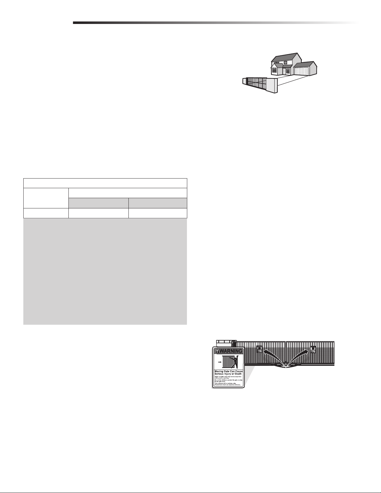
This model is for use on vehicular passage gates
ONLY and not intended for use on pedestrian
passage gates.
This model is intended for use in Class I
vehicular slide gate applications.
Page 2

TABLE OF CONTENTS
SAFETY 1
SAFETY SYMBOL AND SIGNAL WORD REVIEW . . . . . . . . . . . . . . . . . . . . . . . . . . . . 1
UL325 MODEL CLASSIFICATIONS . . . . . . . . . . . . . . . . . . . . . . . . . . . . . . . . . . . . . 2
SAFETY INSTALLATION INFORMATION . . . . . . . . . . . . . . . . . . . . . . . . . . . . . . . . . . 3
GATE CONSTRUCTION INFORMATION . . . . . . . . . . . . . . . . . . . . . . . . . . . . . . . . . . 4
REQUIRED ENTRAPMENT PROTECTION DEVICES . . . . . . . . . . . . . . . . . . . . . . . . . . . 5
IMPORTANT SAFETY INFORMATION . . . . . . . . . . . . . . . . . . . . . . . . . . . . . . . . . . . . 6
INTRODUCTION 7
OPERATOR SPECIFICATIONS . . . . . . . . . . . . . . . . . . . . . . . . . . . . . . . . . . . . . . . . . 7
CARTON INVENTORY . . . . . . . . . . . . . . . . . . . . . . . . . . . . . . . . . . . . . . . . . . . . . . 7
OPERATOR DIMENSIONS . . . . . . . . . . . . . . . . . . . . . . . . . . . . . . . . . . . . . . . . . . . 7
PREPARATION 8
TOOLS AND MATERIALS . . . . . . . . . . . . . . . . . . . . . . . . . . . . . . . . . . . . . . . . . . . . 8
WIRING CHART . . . . . . . . . . . . . . . . . . . . . . . . . . . . . . . . . . . . . . . . . . . . . . . . . . 8
SITE PREPARATION . . . . . . . . . . . . . . . . . . . . . . . . . . . . . . . . . . . . . . . . . . . . . . . . 8
INSTALLATION 9
PREPARE AND INSTALL THE MOUNTING PLATE . . . . . . . . . . . . . . . . . . . . . . . . . . . . 9
PREPARE AND INSTALL THE MOUNTING PLATE . . . . . . . . . . . . . . . . . . . . . . . . . . . 10
INSTALL THE CHAIN (MODEL BX243C ONLY) . . . . . . . . . . . . . . . . . . . . . . . . . . . . 11
INSTALL THE OPERATOR (MODEL BX243C ONLY) . . . . . . . . . . . . . . . . . . . . . . . . . 12
INSTALL THE OPERATOR (MODEL BX243C ONLY) . . . . . . . . . . . . . . . . . . . . . . . . . 13
INSTALL THE OPERATOR (MODEL BX243R ONLY). . . . . . . . . . . . . . . . . . . . . . . . . 14
MANUAL RELEASE . . . . . . . . . . . . . . . . . . . . . . . . . . . . . . . . . . . . . . . . . . . . . . . 15
ADJUST THE LIMITS . . . . . . . . . . . . . . . . . . . . . . . . . . . . . . . . . . . . . . . . . . . . . . 15
DETERMINE OPENING DIRECTION OF GATE . . . . . . . . . . . . . . . . . . . . . . . . . . . . . 16
OPTIONAL WIRING 20
ACCESSORY POWER . . . . . . . . . . . . . . . . . . . . . . . . . . . . . . . . . . . . . . . . . . . . . . 20
COMMAND AND CONTROL DEVICES . . . . . . . . . . . . . . . . . . . . . . . . . . . . . . . . . . . 20
WARNING DEVICES. . . . . . . . . . . . . . . . . . . . . . . . . . . . . . . . . . . . . . . . . . . . . . . 20
ADJUSTMENT 21
OPERATIONAL SETTINGS . . . . . . . . . . . . . . . . . . . . . . . . . . . . . . . . . . . . . . . . . . . 21
INDICATOR LEDS . . . . . . . . . . . . . . . . . . . . . . . . . . . . . . . . . . . . . . . . . . . . . . . . 21
FUNCTIONALITY SWITCHES . . . . . . . . . . . . . . . . . . . . . . . . . . . . . . . . . . . . . . . . . 22
TEST PHOTOELECTRIC SENSORS . . . . . . . . . . . . . . . . . . . . . . . . . . . . . . . . . . . . . . 23
PROGRAMMING 24
SAVE THE SETTINGS . . . . . . . . . . . . . . . . . . . . . . . . . . . . . . . . . . . . . . . . . . . . . . 24
INSTALL AND PROGRAM THE
SECURITY+ 2.0™ RADIO CARD . . . . . . . . . . . . . . . . . . . . . . . . . . . . . . . . . . . . . 25
MAINTENANCE 26
MAINTENANCE CHART . . . . . . . . . . . . . . . . . . . . . . . . . . . . . . . . . . . . . . . . . . . . 26
ADDITIONAL SERVICES . . . . . . . . . . . . . . . . . . . . . . . . . . . . . . . . . . . . . . . . . . . . 27
TROUBLESHOOTING 28
DISPOSAL 28
DISPOSAL OF PACKING MATERIALS . . . . . . . . . . . . . . . . . . . . . . . . . . . . . . . . . . . 28
DISPOSAL OF PRODUCT . . . . . . . . . . . . . . . . . . . . . . . . . . . . . . . . . . . . . . . . . . . 28
REPAIR PARTS 29
WARRANTY 30
WIRING 17
OVERVIEW OF ELECTRONIC CARD (ZN5/ZN5U) . . . . . . . . . . . . . . . . . . . . . . . . . . 17
POWER WIRING . . . . . . . . . . . . . . . . . . . . . . . . . . . . . . . . . . . . . . . . . . . . . . . . . 18
WIRE THE ENTRAPMENT PROTECTION DEVICES . . . . . . . . . . . . . . . . . . . . . . . . . . . 18
WIRE THE ENTRAPMENT PROTECTION DEVICES . . . . . . . . . . . . . . . . . . . . . . . . . . . 19
SAFETY
SAFETY SYMBOL AND SIGNAL WORD
REVIEW
When you see these Safety Symbols and Signal Words on the following pages, they
will alert you to the possibility of serious injury or death if you do not comply with
the warnings that accompany them. The hazard may come from something
mechanical or from electric shock. Read the warnings carefully.
When you see this Signal Word on the following pages, it will alert you to the
possibility of damage to your gate and/or the gate operator if you do not comply
with the cautionary statements that accompany it. Read them carefully.
IMPORTANT NOTE
• BEFORE attempting to install, operate or maintain the operator, you must read
and fully understand this manual and follow all safety instructions.
• DO NOT attempt repair or service of your gate operator unless you are an
Authorized Service Technician.
SAFETY SYMBOL AND SIGNAL WORD REVIEW
MECHANICAL
ELECTRICAL
1
Page 3
SAFETY
UL325 MODEL CLASSIFICATIONS
CLASS I – RESIDENTIAL VEHICULAR GATE OPERATOR
A vehicular gate operator (or system) intended for use in a home of one-to four
single family dwellings, or a garage or parking area associated therewith.
UL325 ENTRAPMENT PROTECTION REQUIREMENTS
This chart illustrates the entrapment protection requirements for the UL325 classes.
GATE OPERATOR ENTRAPMENT PROTECTION
UL325 Classification Slide Gate Operator
Primary Type Secondary Type
CLASS I-CLASS IV A B1 or B2
UL325 MODEL CLASSIFICATIONS
In order to complete a proper installation you must satisfy the entrapment
protection chart shown. That means that the installation must have one primary
means of entrapment protection and one independent secondary means of
entrapment protection. Both primary and secondary entrapment protection
methods must be designed, arranged or configured to protect against
entrapments in both the open and close directions of gate travel.
For Example: For a gate system that is installed on a single-family residence
(UL325 Class I) you must provide the following: As your primary type of
entrapment protection you must provide
• Type A - Inherent (built into the operator) entrapment sensing and at
least one of the following as your secondary entrapment
protection:
• Type B1 - Non-contact sensors such as photoelectric sensors,
• Type B2 - Contact sensors such as gate edges
NOTE: UL requires that all installations must have warning signs placed in plain
view on both sides of the gate to warn pedestrians of the dangers of motorized gate
systems.
2
Page 4

SAFETY
SAFETY INSTALLATION INFORMATION
SAFETY INSTALLATION INFORMATION
1. Vehicular gate systems provide convenience and security. Gate systems are comprised of many component parts. The gate operator is only one component. Each gate
system is specifically designed for an individual application.
2. Gate operating system designers, installers and users must take into account the possible hazards associated with each individual application. Improperly designed, installed
or maintained systems can create risks for the user as well as the bystander. Gate systems design and installation must reduce public exposure to potential hazards.
3. A gate operator can create high levels of force in its function as a component part of a gate system. Therefore, safety features must be incorporated into every design.
Specific safety features include:
• Gate Edges • Guards for Exposed Rollers
• Photoelectric Sensors • Screen Mesh
• Vertical Posts • Instructional and Precautionary Signage
4. Install the gate operator only when:
a. The operator is appropriate for the construction and the usage class of the gate.
b. All openings of a horizontal slide gate are guarded or screened from the bottom of the gate to a minimum of 4 feet (1.2 m) above the ground to prevent a 2-1/4
inches (6 cm) diameter sphere from passing through the openings anywhere in the gate, and in that portion of the adjacent fence that the gate covers in the open
position.
c. All exposed pinch points are eliminated or guarded, and guarding is supplied for exposed rollers.
5. The operator is intended for installation only on gates used for vehicles. Pedestrians must be supplied with a separate access opening. The pedestrian access opening shall
be designed to promote pedestrian usage. Locate the gate such that persons will not come in contact with the vehicular gate during the entire path of travel of the vehicular
gate.
6. The gate must be installed in a location so that enough clearance is supplied between the gate and adjacent structures when opening and closing to reduce the risk of
entrapment. Swinging gates shall not open into public access areas.
7. The gate must be properly installed and work freely in both directions prior to the installation of the gate operator.
8. Controls intended for user activation must be located at least 6 feet (1.8 m) away from any moving part of the gate and where the user is prevented from reaching over,
under, around or through the gate to operate the controls. Outdoor or easily accessible controls shall have a security feature to prevent unauthorized use.
9. The Stop and/or Reset (if provided separately) must be located in the line-of-sight of the gate. Activation of the reset control shall not cause the operator to start.
10. A minimum of two (2) WARNING SIGNS shall be installed, one on each side of the gate where easily visible.
11. For a gate operator utilizing a non-contact sensor:
a. Reference owner’s manual regarding placement of non-contact sensor for each type of application.
b. Care shall be exercised to reduce the risk of nuisance tripping, such as when a vehicle trips the sensor while the gate is still moving.
c. One or more non-contact sensors shall be located where the risk of entrapment or obstruction exists, such as the perimeter reachable by a moving gate or barrier.
12. For a gate operator utilizing a contact sensor such as an edge sensor:
a. One or more contact sensors shall be located where the risk of entrapment or obstruction exists, such as at the leading edge, trailing edge and post mounted both inside
and outside of a vehicular horizontal slide gate.
b. One or more contact sensors shall be located at the bottom edge of a vehicular vertical lift gate.
c. A hard wired contact sensor shall be located and its wiring arranged so the communication between the sensor and the gate operator is not subject to mechanical
damage.
d. A wireless contact sensor such as the one that transmits radio frequency (RF) signals to the gate operator for entrapment protection functions shall be located where the
transmission of the signals are not obstructed or impeded by building structures, natural landscaping or similar obstruction. A wireless contact sensor shall function
under the intended end-use conditions.
e. One or more contact sensors shall be located on the inside and outside leading edge of a swing gate. Additionally, if the bottom edge of a swing gate is greater than 6
inches (152 mm) above the ground at any point in its arc of travel, one or more contact sensors shall be located on the bottom edge.
f. One or more contact sensors shall be located at the bottom edge of a vertical barrier (arm).
3
Page 5

SAFETY
GATE CONSTRUCTION INFORMATION
GATE CONSTRUCTION INFORMATION
Vehicular gates should be installed in accordance with ASTM F2200: Standard Specification for Automated Vehicular Gate Construction. For a copy, contact ASTM directly at
610-832-9585 or www.astm.org.
1. GENERAL REQUIREMENTS
1.1 Gates shall be constructed in accordance with the provisions given for the
appropriate gate type listed, refer to ASTM F2200 for additional gate types.
1.2 Gates shall be designed, constructed and installed to not fall over more than
45 degrees from the vertical plane, when a gate is detached from the
supporting hardware.
1.3 Gates shall have smooth bottom edges, with vertical bottom edged
protrusions not exceeding 0.50 inches (12.7 mm) when other than the
exceptions listed in ASTM F2200.
1.4 The minimum height for barbed tape shall not be less than 8 feet (2.44 m)
above grade and for barbed wire shall not be less than 6 feet (1.83 m)
above grade.
1.5 An existing gate latch shall be disabled when a manually operated gate is
retrofitted with a powered gate operator.
1.6 A gate latch shall not be installed on an automatically operated gate.
1.7 Protrusions shall not be permitted on any gate, refer to ASTM F2200 for
Exceptions.
1.8 Gates shall be designed, constructed and installed such that their movement
shall not be initiated by gravity when an automatic operator is disconnected.
1.9 A pedestrian gate shall not be incorporated into a vehicular gate panel or
that portion of the adjacent fence that the gate covers in the open position.
2. SPECIFIC APPLICATIONS
2.1 Any non-automated gate that is to be automated shall be upgraded to
conform to the provisions of this specification.
2.2 This specification shall not apply to gates generally used for pedestrian
access and to vehicular gates not to be automated.
3.1.3 A gap, measured in the horizontal plane parallel to the roadway, between a
fixed stationary object nearest the roadway, (such as a gate support post)
and the gate frame when the gate is in either the fully open position or the
fully closed position, shall not exceed 2 1/4 inches (57 mm), refer to ASTM
F2200 for Exception.
3.1.4 Positive stops shall be required to limit travel to the designed fully open and
fully closed positions. These stops shall be installed at either the top of the
gate, or at the bottom of the gate where such stops shall horizontally or
vertically project no more than is required to perform their intended
function.
3.1.5 All gates shall be designed with sufficient lateral stability to assure that the
gate will enter a receiver guide, refer to ASTM F2200 for panel types.
3.2 The following provisions shall apply to Class IV vehicular horizontal slide
gates:
3.2.1 All weight bearing exposed rollers 8 feet (2.44 m), or less, above grade
shall be guarded or covered.
3.2.2 Positive stops shall be required to limit travel to the designed fully open and
fully closed positions. These stops shall be installed at either the top of the
gate, or at the bottom of the gate where such stops shall horizontally or
vertically project no more than is required to perform their intended
function.
4. VEHICULAR HORIZONTAL SWING GATES
4.1 The following provisions shall apply to Class 1, Class II and Class III vehicular
horizontal swing gates:
4.1.1 Gates shall be designed, constructed and installed so as not to create an
entrapment area between the gate and the supporting structure or other
fixed object when the gate moves toward the fully open position, subject to
the provisions in the 4.1.1.1 and 4.1.1.2.
2.3 Any existing automated gate, when the operator requires replacement, shall
be upgraded to conform to the provisions of this specification in effect at
that time.
3. VEHICULAR HORIZONTAL SLIDE GATES
3.1 The following provisions shall apply to Class I, Class II and Class III vehicular
horizontal slide gates:
3.1.1 All weight bearing exposed rollers 8 feet (2.44 m), or less, above grade
shall be guarded or covered.
3.1.2 All openings located between 48 inches (1.22 m) and 72 inches (1.83 m)
above grade shall be designed, guarded or screened to prevent a 4 inch
(102 mm) diameter sphere from passing through the openings anywhere in
the gate, and in that portion of the adjacent fence that covers in the open
position.
4.1.1.1 The width of an object (such as a wall, pillar or column) covered by a swing
gate when in the open position shall not exceed 4 inches (102 mm),
measured from the centerline of the pivot point of the gate, refer to ASTM
F2200 for exception.
4.1.1.2 Except for the zone specified in Section 4.1.1.1, the distance between a
fixed object such as a wall, pillar or column, and a swing gate when in the
open position shall not be less than 16 inches (406 mm), refer to ASTM
F2200 for exception.
4.2 Class IV vehicular horizontal swing gates shall be designed, constructed and
installed in accordance with security related parameters specific to the
application in question.
4
Page 6
SAFETY
REQUIRED ENTRAPMENT PROTECTION DEVICES
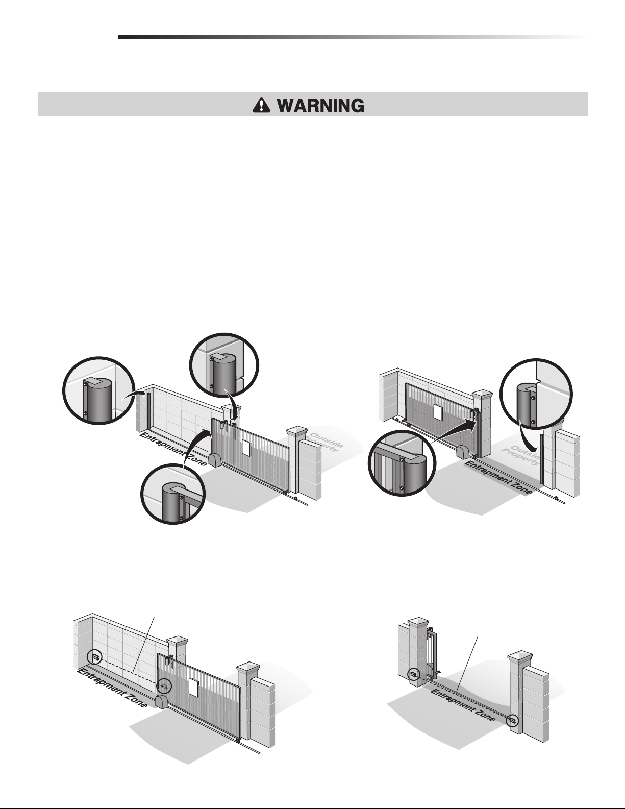
REQUIRED ENTRAPMENT PROTECTION DEVICES
To prevent SERIOUS INJURY or DEATH from a moving gate:
• Entrapment protection devices MUST be installed to protect anyone who may
come near a moving gate.
• Locate entrapment protection devices to protect in BOTH the open and close
gate cycles.
An entrapment zone is every location or point of contact where a person can become entrapped between a moving gate and a stationary object. All gate operator systems
REQUIRE two independent entrapment protection systems for each entrapment zone. This operator contains an inherent (internal) entrapment protection system (the primary
entrapment protection system) and REQUIRES the addition of an external entrapment protection system (non-contact photoelectric sensor or contact safety edge sensor) for
EACH entrapment zone.
Your application may contain one or many entrapment zones. Property owners are obligated to test entrapment protection devices monthly.
CONTACT SENSORS (EDGE SENSORS)
If the electrically activated edge sensor comes in contact with an obstruction while the gate is moving, the gate will stop and reverse. The gate will not be able to travel in that
direction until the obstruction is cleared. Use model G65MGO20, G65MGR20 or G65MGS20.
• Locate entrapment protection devices to protect between moving gate and
RIGID objects, such as posts or walls.
Edge Sensor for Open Cycle
Edge Sensor for Open Cycle
NON-CONTACT SENSORS
Inside
Property
Edge Sensor for Open Cycle
!
Edge Sensor for Close Cycle
!
Inside
Property
Edge Sensor for Close Cycle
If the photoelectric sensor beam gets blocked while the gate is moving, the gate will stop and reverse. The gate will not be able to travel in that direction until the obstruction
is cleared. Use Model DIR10 photoelectric sensors.
Sensor for Open Cycle
Sensor for Close Cycle
!
Inside
Property
Outside
Property
Inside
Property
Outside
Property
5
Page 7
SAFETY
IMPORTANT SAFETY INFORMATION
IMPORTANT SAFETY INFORMATION
To prevent SERIOUS INJURY or DEATH:
• READ AND FOLLOW ALL INSTRUCTIONS.
• Pinch points must be guarded at all times. Install enclosed-style gate tracks and
roller guards.
• Place screen mesh 4 feet (1.2 m) high on the gate to prevent access through
openings anywhere the gate may travel.
• Mount controls at least 6 feet (1.8 m) from the gate or ANY moving part of the
gate.
• Install Warning signs on EACH side of gate in PLAIN VIEW. Permanently secure
each Warning sign in a suitable manner using fastening holes.
• This operator is intended for vehicular use only. To prevent INJURY to
pedestrians, a separate pedestrian access should be supplied, visible from the
gate. Locate the pedestrian access where there is not a chance of INJURY at any
point during full movement of the gate.
• Contact sensors MUST be located at the leading and trailing edges, and post
mounted both inside and outside a horizontal slide gate. Non-contact sensors
such as photo eyes MUST be mounted across the gate opening and operate
during BOTH the open and close cycles.
• Entrapment protection devices MUST be installed to protect anyone who may
come near a moving gate.
• Locate entrapment protection devices to protect in BOTH the open and close
gate cycles.
• Locate entrapment protection devices to protect between moving gate and RIGID
objects, such as posts or walls.
• Too much force on gate will interfere with proper operation of safety reversal
system.
• NEVER increase force beyond minimum amount required to move gate.
• NEVER use force adjustments to compensate for a binding or sticking gate.
• If one control (force or travel limits) is adjusted, the other control may also
need adjustment.
• ANY maintenance to the operator or in the area near the operator MUST NOT
be performed until disconnecting the electrical power. Upon completion of
maintenance the area MUST be cleared and secured, at that time the unit may
be returned to service.
• Disconnect power at the fuse box BEFORE proceeding. Operator MUST be
properly grounded and connected in accordance with national and local
electrical codes.
• After ANY adjustments are made, the safety reversal system MUST be tested.
Gate MUST reverse on contact with a rigid object.
• ALL electrical connections MUST be made by a qualified individual.
• DO NOT install ANY wiring or attempt to run the operator without consulting the
wiring diagram. We recommend that you install an edge sensor BEFORE
proceeding with the control station installation.
• ALL power wiring should be on a dedicated circuit and well protected. The
location of the power disconnect should be visible and clearly labeled.
• ALL power and control wiring MUST be run in separate conduit.
• NEVER let children operate or play with gate controls. Keep the remote control
away from children.
• Without a properly installed safety reversal system, persons (particularly small
children) could be SERIOUSLY INJURED or KILLED by a moving gate.
• ALWAYS keep people and objects away from the gate. NO ONE SHOULD CROSS
THE PATH OF THE MOVING GATE.
• The entrance is for vehicles ONLY. Pedestrians MUST use separate entrance.
• Test the gate operator monthly. The gate MUST reverse on contact with a rigid
object or reverse when an object activates the non-contact sensors. After
adjusting the force or the limit of travel, retest the gate operator. Failure to
adjust and retest the gate operator properly can increase the risk of INJURY or
DEATH.
• Use the manual disconnect release ONLY when the gate is not moving.
• KEEP GATES PROPERLY MAINTAINED. Read the owner’s manual. Have a
qualified service person make repairs to gate hardware.
• ALL maintenance MUST be performed by a trained professional.
• Activate gate ONLY when it can be seen clearly, is properly adjusted and there
are no obstructions to gate travel.
• SAVE THESE INSTRUCTIONS.
To protect against fire and electrocution:
• DISCONNECT power BEFORE installing or servicing operator.
• To AVOID damaging gas, power or other underground utility lines, contact
underground utility locating companies BEFORE digging more than 18 inches
(46 cm) deep.
For continued protection against fire:
• Replace ONLY with fuse of same type and rating.
6
Page 8
INTRODUCTION
OPERATOR SPECIFICATIONS
This model is intended for use in vehicular slide gate applications:
OPERATOR SPECIFICATIONS + CARTON INVENTORY + OPERATOR DIMENSIONS
Gate Classifications: CLASS I
Main AC Supply: 120 Vac, 50/60Hz
Input Rating: 170 Watts at 120Vac
Main Supply (Motor): 7 Amps at 24Vdc
Accessory Power: 24 Vac 1.5A
Full Cycle Time: 7.87 inches/second
Fuse Protection Motor: 8A-F 250 Vac 6x32mm
Fuse Protection Control Board: 1A-F 250 Vac 5x20mm
Fuse Protection AC Line: 3.15A-F 250 Vac 5x20mm
Fuse Protection Accessories: 1.6A-F 250 Vac 5x20mm
* The company CAME Cancelli Automatici is ISO 9001:2000 quality certified; it has
also obtained the ISO 14001 environmental safeguarding certification. CAME
engineers and manufactures all of its products in Italy.
Maximum Gate Weight/Length: 660 lbs./28 foot
This product complies with the following standards: UL-325 and CSA C22.2 NO.247-
92.
Daily Cycle Rate AC power: 25 cycles/day
Ambient Temperature: -20°C to 55°C (-4°F to 131°F)
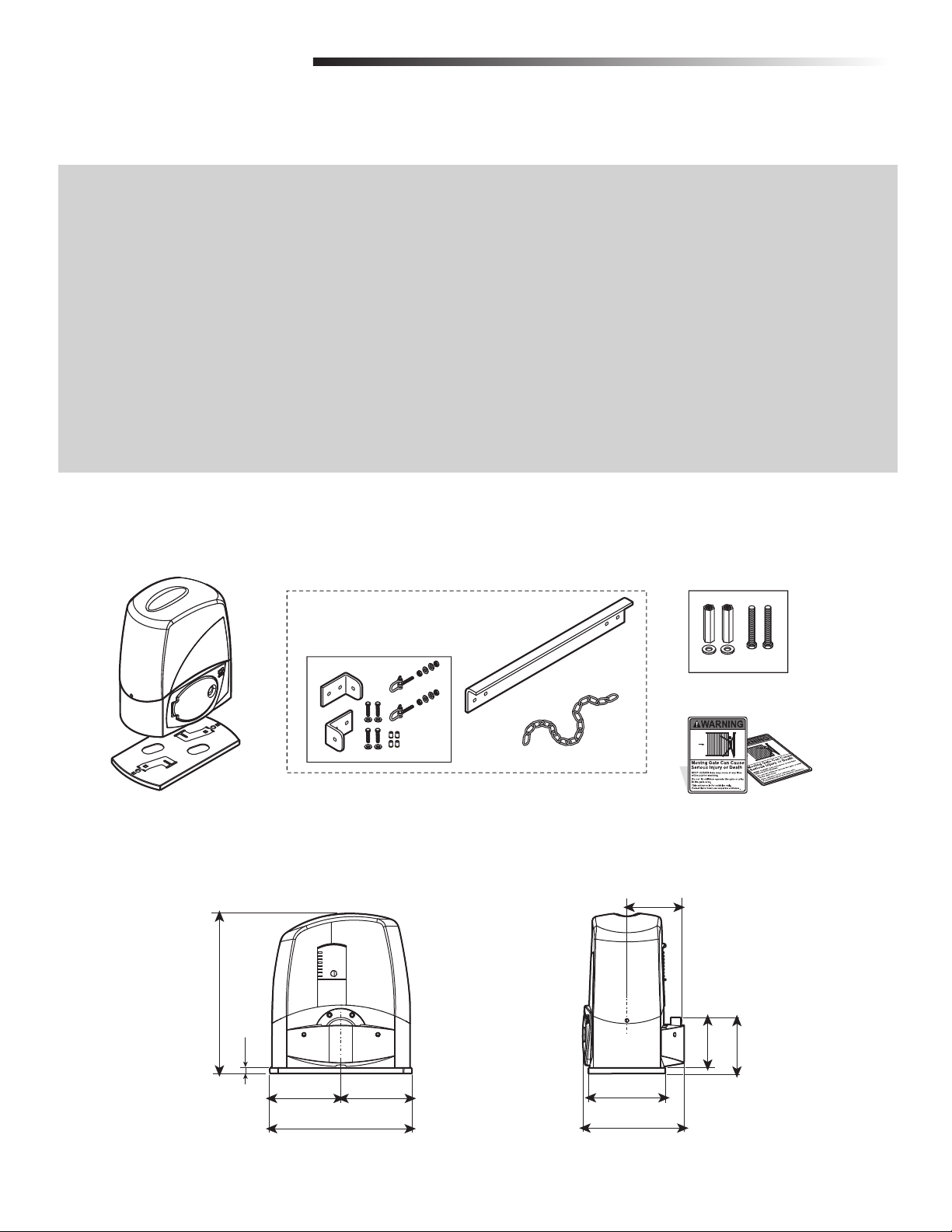
CARTON INVENTORY
NOT SHOWN: Hardware bag with rubber plugs and fuses (packaged inside of operator), keys, and manual.
Operator
MODEL BX243C ONLY
Mounting Plate
OPERATOR DIMENSIONS
13" (33 cm)
.93" (2.32 cm)
Hardware Bag for Chain
5.87" (14.9 cm)
5.87" (14.9 cm)
Extension Bracket
Chain
4.49" (11.4 cm)
6.37" (16.17 cm)
Hardware Bag to anchor Operator
Warning Signs (2)
4.13" (10.49 cm)
4.63" (11.70 cm)
11.7" (29.71 cm)
8.35" (21.20 cm)
7
Page 9
PREPARATION
TOOLS AND MATERIALS
Make sure you have all the tools and materials required for the installation. The
installation should be completed in accordance with all national and local standards
and regulations.
The following tools may be needed for your installation:
• Drill and Drill Bits
• Hack Saw
• Welder
• Tape Measure
• Pliers
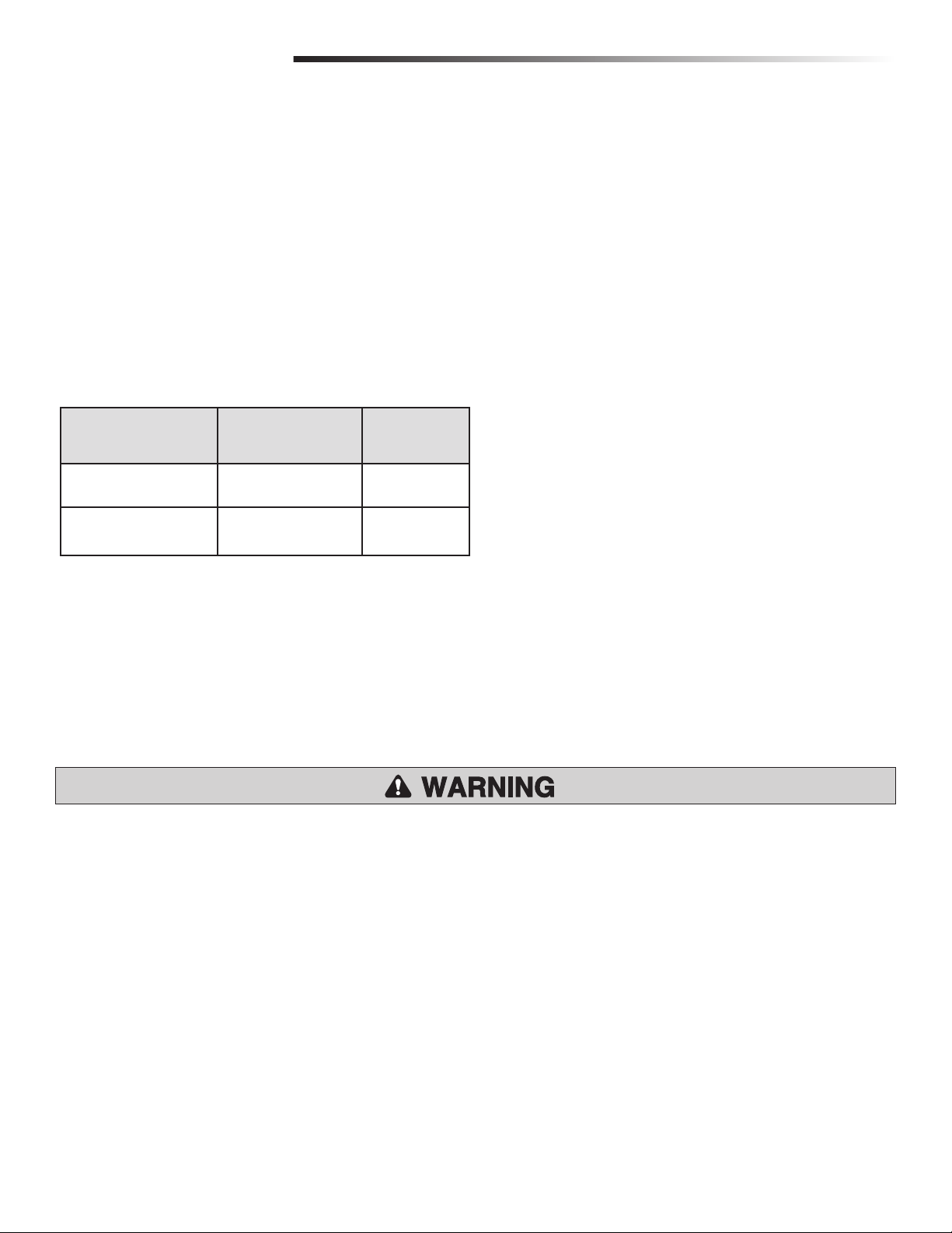
WIRING CHART
Always check first for local and national electrical codes.
• Open End Wrenches
• Screwdrivers
• Shears
• Level
• C-Clamps (Model BX243R Only)
TOOLS AND MATERIALS + WIRING CHART
CONNECTION/DEVICE AMERICAN WIRE GAUGE
(AWG)
Control panel power supply
120V
Safety and control
NOTE: If the length of the wire differs from that specified in the table, then you
must determine the proper wire gauge based on the actual power draw of the
devices connected and the local electrical codes. For connections that require several,
sequential loads, the sizes provided in the table must be re-evaluated based on
actual power draw and distances. When connecting products that are not specified in
this manual, refer to the instructions provided with said products.
NOTE: Use copper conductors only.
devices
14AWG 3 ft. up to 100 ft.
20AWG 3 ft. up to 100 ft.
WIRE LENGTH
SITE PREPARATION
INSTALLATION MUST BE PERFORMED BY AN EXPERT QUALIFIED PERSONNEL AND IN FULL COMPLIANCE WITH
CURRENT REGULATIONS. Gate must be constructed and installed according to ASTM F2200 standards.
Before installation, perform the following:
Make sure that the gate is stable, and that the castors are in good working order and properly greased.
1
The ground rack must be well secured to the ground, entirely above the surface and free of any irregularities that may obstruct the gate’s movement.
2
The upper guide rails must not create any friction.
3
Make sure that there is a closing and an opening endstops.
4
Make sure that the operator is attached to a solid surface and protected from any impacts;
5
Make sure you have a suitable omnipolar cut-off device with contacts more than 1/32” (3 mm) apart, and independent (sectioned off) power supply;
6
Check that any connections inside the container (that provide continuity to the safety circuit) are fitted with additional insulation compared to other internal live parts;
7
Make sure you have suitable tubing and conduits for the electrical cables to pass through and be protected against mechanical damage.
8
8
Page 10
INSTALLATION
1.57" (3.98 cm)
9.44"
(23.97 cm)
15.74"
(39.97 cm)
12" (30.47 cm)
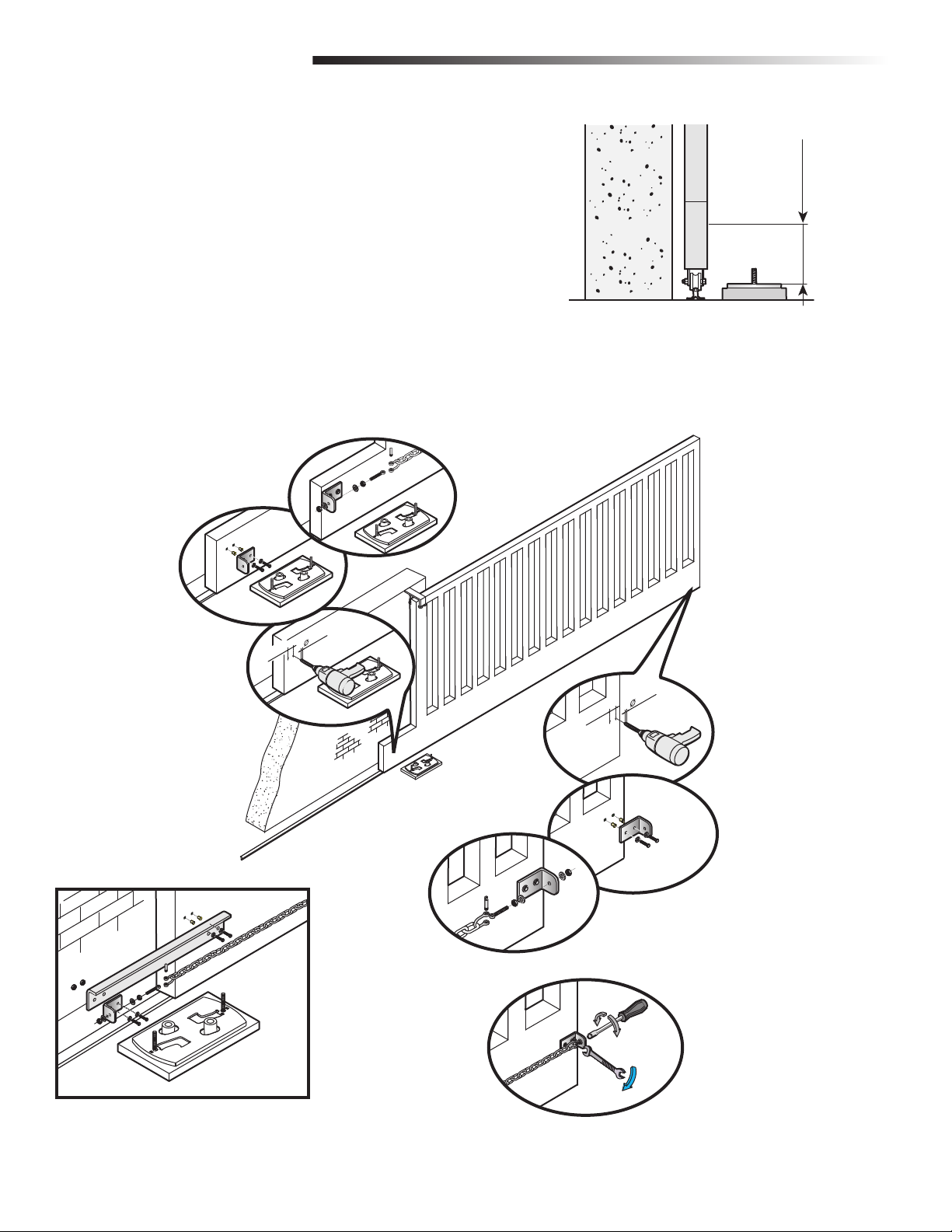
PREPARE AND INSTALL THE MOUNTING
PLATE
The instructions and illustrations in this manual are examples ONLY. Your installation
may vary depending on space, obstructions, and accessories. It is up to the installer
to select the most suitable solution.
Dig a hole to the side of the gate (Figure 1). The concrete pad should be
1
deeper than the frost line. Check all national and local codes.
Prepare a trench and install the electrical conduit. All conduit should be 3/4"
2
diameter maximum.
NOTE: The number of conduits will depend on your site and the accessories to
be installed.
Prepare a form box larger than the mounting plate and insert the form box in
3
the hole (Figure 2). The form box should be 1-3/4” (50 mm) above the
ground (Figure 2).
Insert an iron grid inside the form to reinforce the concrete (Figure 2).
4
Insert the bolts into the holes of the mounting plate and secure with nuts and
5
washers supplied (Figure 3).
PREPARE AND INSTALL THE MOUNTING PLATE
• To AVOID damaging gas, power or other underground utility lines, contact
underground utility locating companies BEFORE digging more than 18 inches
(46 cm) deep.
FIGURE 1
Extend the preformed tabs on the mounting plate with a screwdriver or a pair
6
of pliers (Figure 3).
FIGURE 2
Electrical conduit
Junction Box
FIGURE 3
1-3/4" (50 mm)
9
Page 11
INSTALLATION
PREPARE AND INSTALL THE MOUNTING PLATE
PREPARE AND INSTALL THE MOUNTING
PLATE
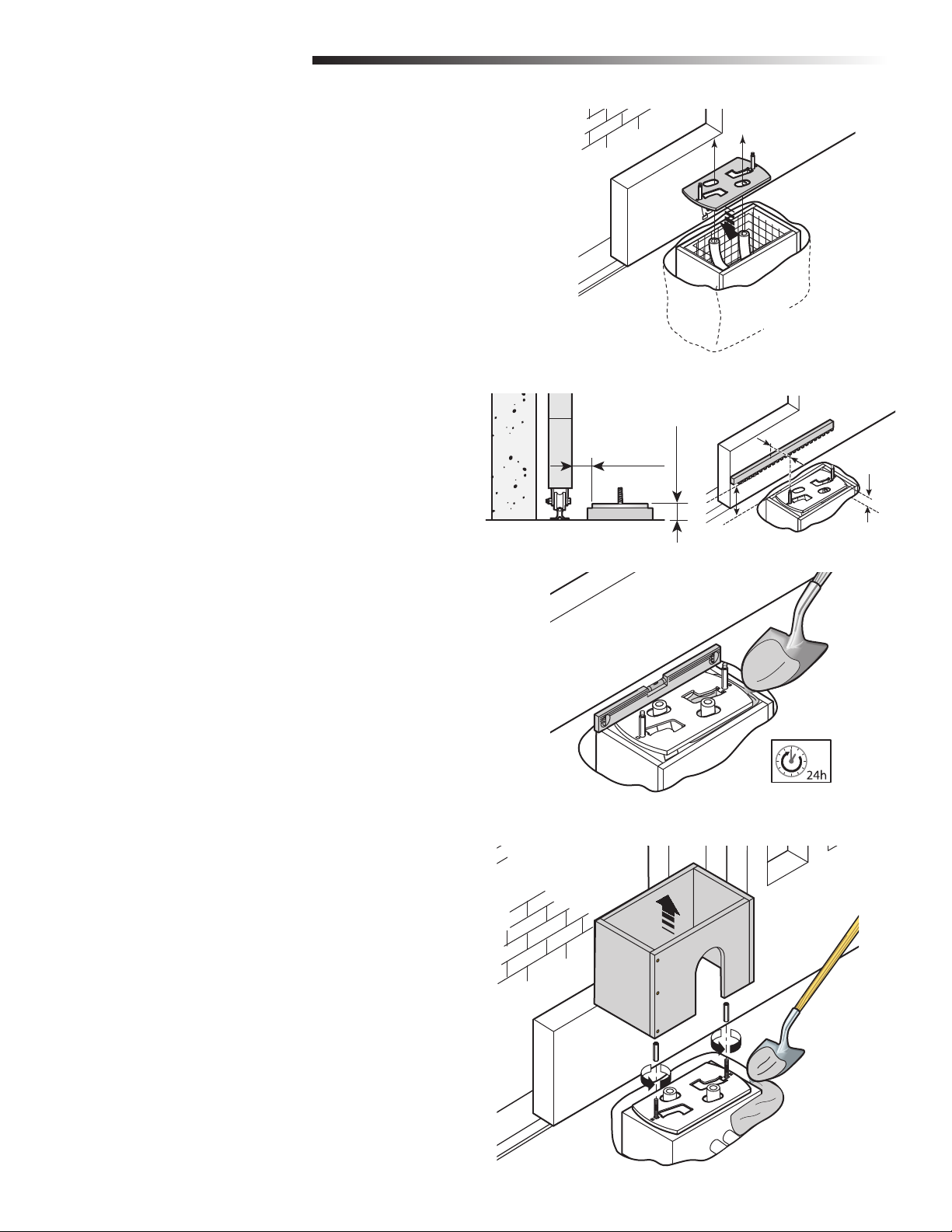
Position the mounting plate on top of the grid (Figure 4). Conduit must be run
7
through separate knockouts.
Position the mounting plate relative to the gate (Figure 5).
8
Fill the form box with concrete and wait for at least 24 hours to allow the
9
concrete to cure (Figure 6).
Remove the form box (Figure 7).
10
Fill the hole around the concrete form with soil (Figure 7).
11
Remove the nuts and washers from the bolts (Figure 7). The mounting plate
12
must be clean, perfectly level and with the bolt threads completely above the
surface.
For model BX243C (Chain) proceed to page 11.
For model BX243R proceed to page 14.
FIGURE 4
FIGURE 5
MODEL BX243C MODEL BX243R
3.54”
2.17”
1.97”
4.13”
1.97”
FIGURE 6
FIGURE 7
10
Page 12
INSTALLATION
1.18"
INSTALL THE CHAIN (MODEL BX243C ONLY)
INSTALL THE CHAIN (MODEL BX243C ONLY)
Measure up 4-5/16 inches (110 mm) from the top of the mounting plate. Drill
1
two holes for the back gate bracket and two holes for the front gate bracket
(Figure 2).
Insert the bushings into the holes. Fasten the front and back gate brackets with
2
bolts and washers (Figure 2).
Attach the chain to the gate brackets with hardware supplied (Figure 2). If the
3
chain is too long, cut off the excess. If necessary, fasten the extension bracket
to the back side of the gate to allow the gate to open and close fully (Figure 3).
Adjust the chain tension by turning the outer nut. Tighten the inner nut to secure
4
the adjustment (Figure 4).
FIGURE 2
FIGURE 1
4-5/16" (110 mm)
FIGURE 3
.43"
.43"
1.18"
FIGURE 4
11
Page 13
INSTALLATION
INSTALL THE OPERATOR (MODEL BX243C ONLY)
INSTALL THE OPERATOR (MODEL BX243C
ONLY)
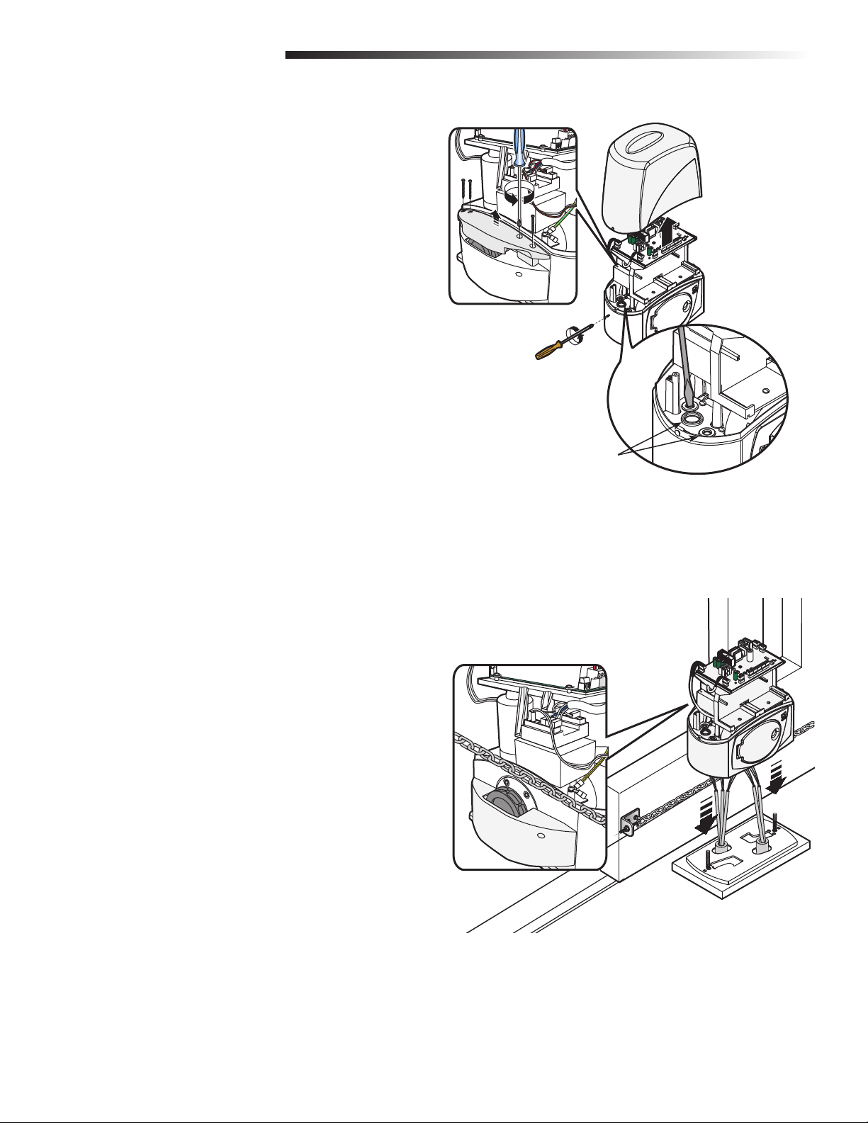
Remove the two screws on the side of operator and remove the cover.
1
Insert the rubber plugs into the holes in the bottom of the operator. Use a
2
screwdriver or a pair of scissors to puncture the rubber plug to allow the wires
to be threaded through (Figure 1A).
Remove the four screws that secure the pulley cover to the operator
3
(Figure 1B).
Run the electrical wires through the conduit, allow at least 15-3/4 inches
4
(400 mm) to protrude (Figure 2A).
Position the operator over the mounting plate and pull electrical wires through
5
the rubber plugs. Lower operator on to the mounting plate. Align the pulley
with the chain (Figure 2B).
FIGURE 1B
FIGURE 1A
Rubber Plugs
FIGURE 2B
FIGURE 2A
12
Page 14
INSTALLATION
INSTALL THE OPERATOR (MODEL BX243C
ONLY)
Position the operator using the four leveling feet for vertical adjustments and
6
the slots for horizontal adjustments (Figure 1A).
Once adjustments are complete, secure the operator with the bolts and nuts
7
(Figure 1B).
Re-attach the pulley cover with four screws (Figure 1C).
8
Secure the cover with a screw on each side (Figure 1D).
9
FIGURE 1C
INSTALL THE OPERATOR (MODEL BX243C ONLY)
FIGURE 1B
FIGURE 1D
FIGURE 1A
13
Page 15
INSTALLATION
INSTALL THE OPERATOR (MODEL BX243R ONLY)
INSTALL THE OPERATOR (MODEL BX243R
ONLY)
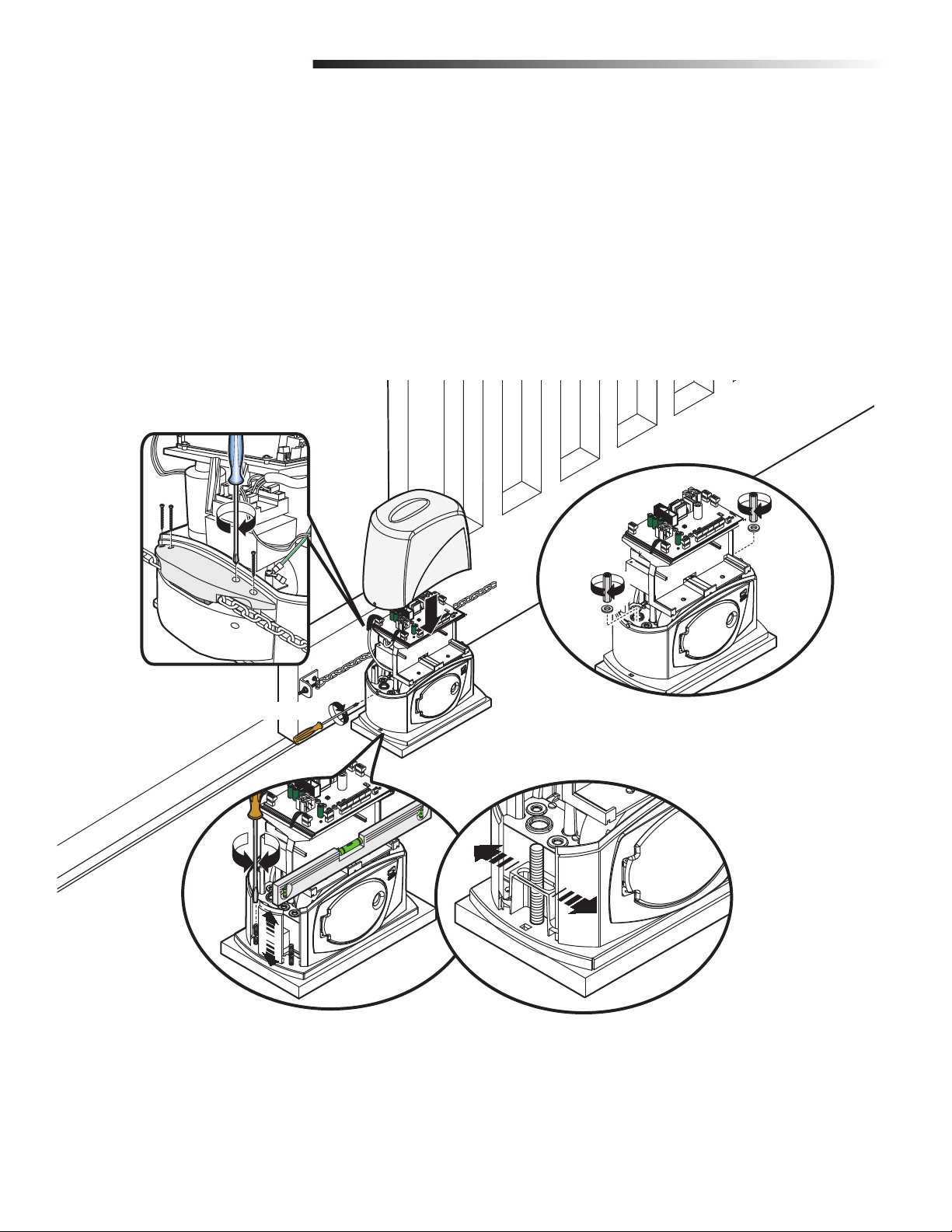
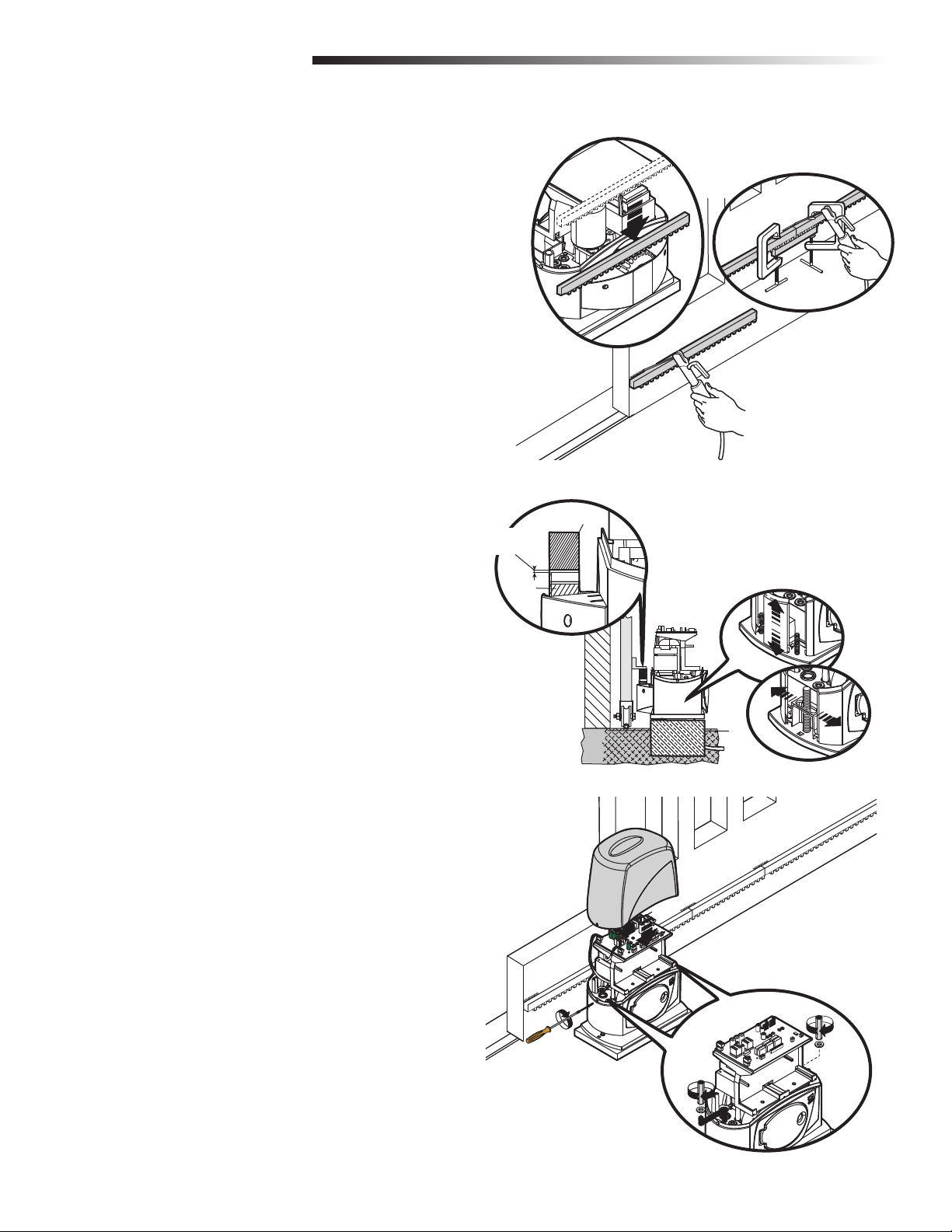
Release the operator by pulling the release lever (refer to page 15).
1
Rest the rack on the gearmotor pinion (Figure 1).
2
To assemble the rack modules, use an excess piece of rack and place it under
3
the joint. Secure the rack pieces with two C-clamps (Figure 1B).
Weld the rack to the gate along its entire length (Figure 1C).
4
Open and close the gate manually and register the rack to pinion distance
5
using the levelling feet (for vertical adjustment) and the slotted holes (for
horizontal adjustment) (Figure 2).
Secure the operator using the nuts and washers (Figure 3).
6
Secure the cover with a screw on each side (Figure 3).
7
FIGURE 1A
FIGURE 1B
FIGURE 1C
FIGURE 2
Rack
Coupling Distance
(1/32-5/64")
Pinion
FIGURE 3
14
Page 16
INSTALLATION
MANUAL RELEASE
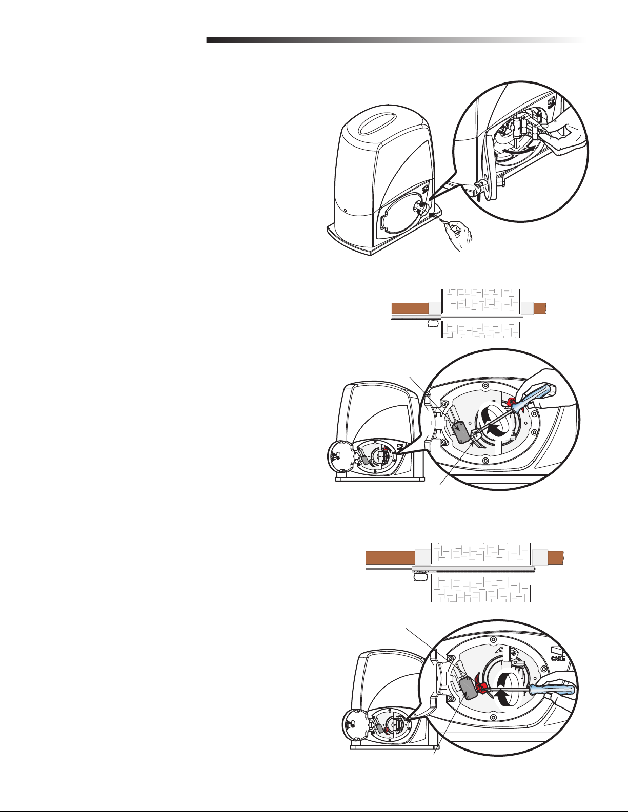
Insert the key and turn it counter-clockwise. Open the release door and pull
1
the release lever.
MANUAL RELEASE + ADJUST THE LIMITS
ADJUST THE LIMITS
The operator is factory configured for a left-handed installation. To change to a
right-hand installation, reverse the wiring for the motor (M-N) and limit switches (FAFC) on the electronic card (ZN5/ZN5U), see page 16 for a wiring diagram.
OPEN LIMIT
Manually release the operator and fully open the gate.
1
Loosen the screw on the white cam.
2
Slide the white cam clockwise until it makes contact with the limit switch.
3
Tighten the screw on the white cam to lock the adjustment.
4
CLOSE LIMIT
Manually release the operator and fully close the gate.
1
Loosen the screw on the red cam.
2
Open Limit
Limit switch
White cam
Close Limit
Slide the red cam counter-clockwise until it makes contact with the limit switch.
3
Tighten the screw on the red cam to lock the adjustment.
4
Red cam
Limit switch
15
Page 17
INSTALLATION
DETERMINE OPENING DIRECTION OF GATE
DETERMINE OPENING DIRECTION OF GATE
MOTOR AND LIMIT SWITCHES (OPEN TO THE LEFT)
The operator is factory configured for a left-handed installation.
Orange
White
Orange
Red
Open limit switch
COM
NC
COM
NC
Close limit switch
LEFT-HAND
Left-handed (factory default)
24V (AC) motor with encoder
White
Brown
Green
Red
Green
% &# &! &
- .
MOTOR AND LIMIT SWITCHES (OPEN TO THE RIGHT)
To change to a right-hand installation, reverse the wiring for the motor (M-N) and
limit switches (FA-FC).
COM
NC
COM
NC
White
Red
RIGHT-HAND
Right-handed
24V (AC) motor with encoder
Red
Green
% &# &! &
- .
16
Page 18
WIRING
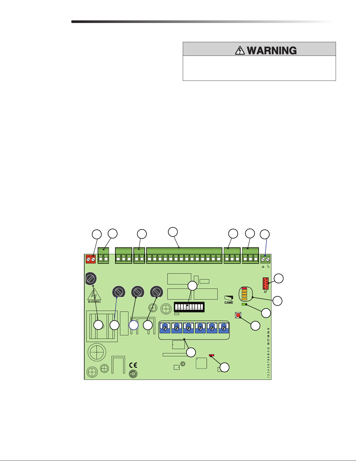
OVERVIEW OF ELECTRONIC CARD
(ZN5/ZN5U)
1 Power Supply Terminals
2 Limit Switch Terminals
3 Motor Terminals
4 Encoder Terminals
5 Accessory Fuse
6 Card Fuse
7 Program Button
8 Radio/Alert LED
9 120V-Power LED
10 Control and Signalling LED Group
11 Function Selector DIP Switch
12 Security+ 2.0™ radio card connector
13 Antenna Terminal
14 Accessory and Command Device Terminals
15 Motor Fuse
16 Line Fuse
17 Operational Settings
18 Transformer Terminals
OVERVIEW OF ELECTRONIC CARD + POWER WIRING
To protect against fire and electrocution:
•
DISCONNECT power BEFORE installing or servicing operator.
1
L1T
LN
L1T
LINE FUSE
230V=1.6A-F
120V=3.15A-F
16
18
L2T
L2T
BX246=10A-F
26
17
26
17
MOTOR FUSE
BX243=8A-F
15
MN
0
MN
0
ACCESSORIES
FUSE
1.6A-F
5
FUSE
1A-F
14
11
ON
1345678910
2
3
10 11 E1 1 2 3P 5 7 2 C1 C3 C7 C8
10 11 E1 1 2 3P 5 7 2 C1 C3 C7 C8
C. BOARD
6
+
RUN S.
- +
SLOW S.
- +
RUN V.
- +
17
SLOW V.
CONTROL BOARD
-
+
PAR.OP.
TS
+E
TS
+E
ZN5
ZN5U5
+
A.C.T.
-
-
8
2
4
FC FA
-
FC FA
-
13
F
F
12
1
C1
C3
C7
C8
PWR
10
9
PROG
7
17
Page 19
WIRING
POWER WIRING + WIRE THE ENTRAPMENT PROTECTION DEVICES
POWER WIRING
Connect 120 Vac to L-N terminals on the electronic card, 50/60Hz frequency
1
maximum.
The electronic card is equipped with an amperometric sensor which constantly
monitors the motor’s drive. If the gate encounters an obstacle, the sensor
immediately detects the overload on the operator and the gate reverses.
Do not apply AC power until instructed.
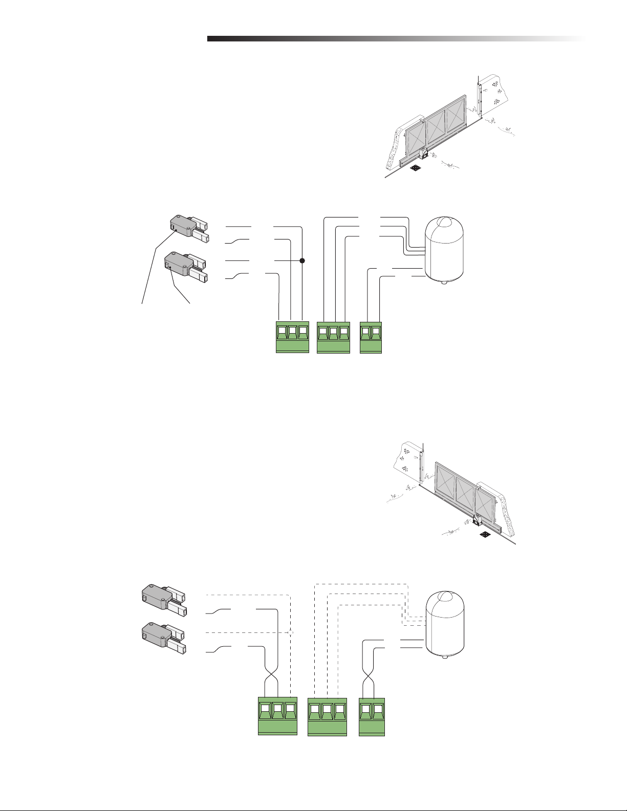
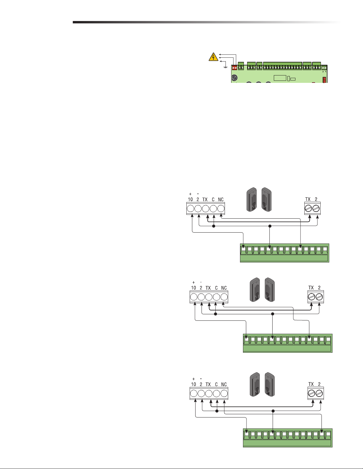
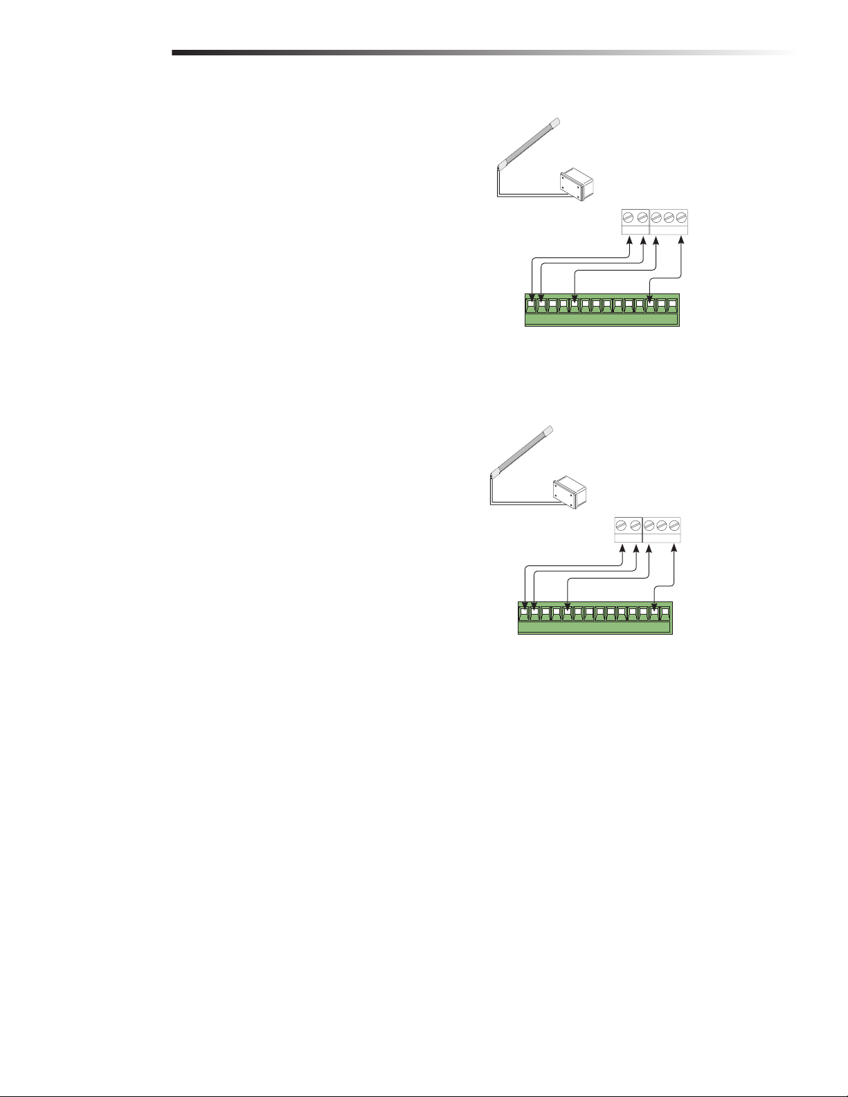
WIRE THE ENTRAPMENT PROTECTION
DEVICES
An entrapment protection device such as photoelectric sensors or an edge MUST be
wired to the operator and then configured for your application. NOTE: If entrapment
protection devices are not used, you must jumper the connections to disable the
contacts.
PHOTOELECTRIC SENSOR CONFIGURATIONS
“OPENING DURING CLOSING” (N.C.) CONTACT
If contact is opened while the gate is closing, the gate reverses direction. To select this
function set the number 9 functionality switch to OFF (refer to the "Functionality
Switches" chart on page 22). Default is OFF. To disable this function set the number
9 functionality switch to ON.
120 Vac Power, 50/60Hz Frequency
L1T
L2T
LN
L1T
L2T
LINE FUSE
230V=16A F
120V=315A F
DIR10 Photoelectric Sensors: Opening During Closing
RX
MN
17
0
26
MN
0
26
17
10 11 E1 1 2 3P 5 7 2 C1 C3 C7 C8
10 11 E1 1 2 3P 5 7 2 C1 C3 C7 C8
C BOARD
FUSE
1A F
TS
TS
CONTROL BOARD
ZN5
+E
+E
TX
FC FA
FC FA
F
F
“PARTIAL STOP” (N.C.) CONTACT
Gate stops if moving and automatically shuts (if this function has been selected). To
select this function set the number 10 functionality switch to OFF (refer to the
"Functionality Switches" chart on page 22). Default is OFF. To disable this function
set the number 10 functionality switch to ON.
“CLOSE WHILE OPENING” (N.C.) Contact
This input functions to reverse the gate to the close limit when the photoelectric
sensor is activated during the opening cycle.
NOTE: If not used, short circuit contact 2-C8.
RX
RX
% 0 # # # #
DIR10 Photoelectric Sensors: Partial Stop
% 0 # # # #
DIR10 Photoelectric Sensors: Close While Opening
43
TX
43
TX
18
% 0 # # # #
43
Page 20
WIRING
WIRE THE ENTRAPMENT PROTECTION DEVICES
WIRE THE ENTRAPMENT PROTECTION
DEVICES
EDGE SENSORS (CONTACT)
“OPEN WHILE CLOSING” (N.C.) Contact
This input functions to reverse the gate to the open limit when activated during the
close cycle.
NOTE: If not used, short circuit contact 2-C7.
“CLOSE WHILE OPENING” (N.C.) Contact
This input functions to reverse the gate to the close limit when the edge is activated
during the opening cycle.
NOTE: If not used, short circuit contact 2-C8.
Two-wire normally open edge
Wireless Communicator
PWR Relay
Transmitter
24V C
CNONC
%0####
Two-wire normally open edge
Wireless Communicator
PWR Relay
Transmitter
24V C
CNONC
Receiver
43
Receiver
Connect power to the operator.
%0####
43
19
Page 21

OPTIONAL WIRING
ACCESSORY POWER
Command devices and accessories are 24V power. The overall power for accessories
CANNOT exceed 1.5 Amps.
Terminals 10 and 11 provide power for the following accessories:
• 24 Vac normally
ACCESSORY POWER + COMMAND AND CONTROL DEVICES +
WARNING DEVICES
To protect against fire and electrocution:
• DISCONNECT power BEFORE installing or servicing operator.
Cable lug with bolt and washer to secure to ground
+
-
COMMAND AND CONTROL DEVICES
Stop button (N.C. contact)
• Cancels automatic closing (A.C.T.). To resume normal operation, press the
command button or the remote control button. To disable this function set the
number 8 functionality switch to ON.
Key selector and/or partial opening button (N.O. contact)
• Partial gate opening
Key selector and/or command button (N.O. contact)
• Gate opening and closing command.
• By pressing the button or turning the key, the gate reverses direction or stops
depending on the functionality switch settings.
WARNING DEVICES
Open-gate indicator light
• Signals that gate is open; turns off when the gate is closed.
• Contact power: 24V A.C. - 25W maximum
• Socket rating 24V-3W maximum
% 0 # # # #
% 0 # # # #
Warning Device (Siren)
43
43
NOTE: If the operator detects an obstacle in the same direction twice while running,
the electronic card activates the warning device and blocks the signal from the
remote control for 5 minutes. After 5 minutes, the alarm is deactivated and the
signal for the remote controls are restored and the PROG LED goes off. To restore
normal operation prior to the 5 minutes, press the total stop key and the PROG LED
goes off.
20
% 0 # # # #
43
Page 22

ADJUSTMENT
OPERATIONAL SETTINGS
SETTING FUNCTION
A.C.T. (Automatic Close
Timer)
PAR.OP. This setting is used to partially open the gate. By
SLOW S. Sets the force sensitivity during slow down; the operator
RUN S. Sets the force sensitivity during normal movement, the
SLOW V. Sets the gates speed during the slow down phase.
RUN V. Sets the gates opening/closing speed.
The ACT is also referred to as Timer-to-Close. The ACT
can be set to automatically close the gate after a
specified time period. If the ACT is set to the OFF
position, then the gate will remain open until the
operator receives another command from a control.
Rotate the ACT dial to the desired setting. The range is
0 to 150 seconds, 0 seconds is OFF.
pushing a button connected to the 2 and 3P terminals,
the gate partially opens depending on the length of the
gate.
reverses direction if the force exceeds the set level.
operator reverses direction if the force exceeds the set
level.
LN
+
RUN S.
L2T
L1T
L2T
L1T
LINE FUSE
230V=1 6A F
120V=3 15A F
- +
SLOW S.
26
26
MOTOR FUSE
BX243=8A F
BX246=10A F
OPERATIONAL SETTINGS + INDICATOR LEDS
10 11 E1 1 2 3P 5 7 2 C1 C3 C7 C8
MN
0
17
MN
10 11 E1 1 2 3P 5 7 2 C1 C3 C7 C8
0
17
C BOARD
FUSE
1A F
TS
+E
TS
+E
CONTROL BOARD
ZN5
-
-
ZN5U5
- +
ACCESSORIES
FUSE
1 6A F
RUN V.
- +
SLOW V.
+
RUN S
-
ON
1 345678910
2
- +
SLOW S
- +
+
PAR.OP.
RUN V
-
- +
+
SLOW V
A.C.T.
PROG
+
A C T
-
-
+
PAROP
-
-
FC FA
FC FA
F
F
1
C1
C3
C7
C8
PWR
INDICATOR LEDS
LED COLOR FUNCTION
1 Red Normally off. A lit red LED indicates the STOP button is
activated.
C1 Yellow Normally off. A lit yellow LED indicates an obstruction
between the photoelectric sensors (which are in OPEN
WHILE CLOSING mode).
C3 Yellow Normally off. Indicates an obstruction between the
photoelectric sensors (which are in PARTIAL STOP
mode).
C7 Yellow Normally off. Indicates an obstruction was detected by
an edge sensor (which is in OPEN WHILE CLOSING
mode).
C8 Yellow Normally off. Indicates an obstruction was detected by
an edge sensor (which are in CLOSE WHILE OPENING
mode).
PWR Green Green LED. Normally on. Indicates the card is properly
powered up.
Radio/
Alert
Red Red LED. Normally off. The red Radio/Alert LED flashes
or turns on indicating a signal from a remote control.
LN
L2T
L1T
L2T
L1T
LINE FUSE
230V=1 6A F
120V=3 15A F
26
26
MOTOR FUSE
BX243=8A F
BX246=10A F
17
17
Indicator LEDs
MN
10 11 E1 1 2 3P 5 7 2 C1 C3 C7 C8
0
10 11 E1 1 2 3P 5 7 2 C1 C3 C7 C8
MN
0
C BOARD
FUSE
1A F
ACCESSORIES
FUSE
1 6A F
+
RUN S
- +
ON
1 345678910
2
SLOW S
- +
RUN V
- +
SLOW V
-
+
PAROP
1
C1
C3
C7
C8
PWR
TS
+E
TS
+E
ONTROL BOARD
ZN5
ZN5U5
+
A C T
-
-
FC FA
F
-
FC FA
F
-
1
C1
C3
C7
C8
PWR
PROG
NOTE: If Radio/Alert LED is flashing, check unused photoelectric sensor terminals
and place a jumper between 2 and C7, C8. Disable C1 and C3 with the number 9 and
10 functionality switches.
Radio/Alert
LED
21
Page 23

ADJUSTMENT
FUNCTIONALITY SWITCHES
FUNCTIONALITY SWITCHES
SWITCH SETTING FUNCTION
1 ON Automatic Closing - The automatic close timer (ACT) is activated when the gate is open. The pre-set time is adjustable, depending of the
activation of any safety devices, and does not activate after a total safety “stop” or during a blackout.
2 ON “Open-stop-close-stop” function with [2-7] command button and remote control (if a radio frequency card is installed).
OFF “Open-close” function with [2-7] command button and remote control (if a radio frequency card is installed).
3 ON “Open only” function with [2-7] command button and remote control (if a radio frequency card is installed).
4 OFF Not used. Leave OFF.
5 OFF With BX-243 motor.
ON With BX-246 motor.
6 ON Maintained action - The gate activates with constant pressure from command button (one 2-3P opening button, and one 2-7 closing button).
7 ON Functioning of the photoelectric sensors’ safety test - Allows the card to check the efficiency of any safety devices (i.e. photoelectric sensors)
after every opening or closing command.
8 OFF Total stop - This function stops the gate and then excludes any automatic closing cycle; to set in motion again, use either the keypad or
transmitter. Insert the safety device in [1-2]; If unused, set DIP switch to ON.
9 OFF OPENING DURING CLOSING - If the photoelectric sensors detect an obstacle while the gate is closing, the gate reverses until fully opened;
connect the safety device to terminals [2-C1]; if unused, set DIP switch to ON.
10 OFF PARTIAL STOP - Gate stops when an obstacle is detected by the safety device; once the obstacle is removed, the gate remains still or closes
if automatic closing is activated. Connect the safety device to terminal [2-C3]; if unused, set the DIP switch to ON.
LN
L2T
L T
L2T
L1T
L NE FUSE
230V=1 6A F
120V=3 15A F
26
17
26
17
MOTOR FUSE
BX243=8A F
BX246=10A F
MN
10 11 E1 1 2 3P 5 7 2 C1 C3 C7 C8
0
10 11 E1 1 2 3P 5 7 2 C1 C3 C7 C8
MN
0
C BOARD
FUSE
1A F
ACCESSORIES
FUSE
1 6A F
+
RUN S
- +
ON
1 345678910
2
SLOW S
- +
RUN V
Default Setting
TS
TS
CONTROL BOARD
ZN5U5
SLOW V
+
-
+
PAROP
-
- +
+E
+E
ZN5
A C T
-
FC FA
F
-
FC FA
F
-
1
C1
C3
C7
C8
PWR
PROG
/.
ON
OFF
22
Page 24

ADJUSTMENT
TEST PHOTOELECTRIC SENSORS
TEST PHOTOELECTRIC SENSORS
Each open/close command, the electronic card verifies the photoelectric
sensors are connected and working. Any problems with the photoelectric
sensors will cause the (PROG) LED to flash on the electronic card, which
cancels any commands from the remote control or push-button.
Electrical connection to operate the photoelectric sensors safety test:
1
• Connect the transmitter and receiver as shown in the diagram.
• Set DIP switch 7 to ON to activate the test.
When the safety test function is activated, the N.C. contacts:
2
• If unused--are to be excluded on their relative DIP switches (see
“Functionality Switches”).
(DOC)
#
.#
./
% 0 # # # #
(DIR10)
43
#
48
.#
48
% 0 # # # #
43
23
Page 25

PROGRAMMING
+ RUN S. - OW S. - RUN +
ON
2
1345678910
OG.
ON
2
1345678910
SAVE THE SETTINGS
Run the operator through a complete open and close cycle (Figure 1).
1
The electronic card automatically registers the gate-run adjustments for the
2
opening and closing settings (Figure 2).
To save the adjustment, functionality switch 6 to ON and press the PROG
3
button until the PROG LED stays on. (Figure 3)
Move functionality switch 6 to OFF (Figure 4).
4
NOTE: You MUST set the functionality switch to OFF to save the settings to avoid
resetting the adjustments after power outage.
SAVE THE SETTINGS
FIGURE 1
FIGURE 2 FIGURE 3 FIGURE 4
PROG
Functionality Switch 6 in ON
LN
L2T
L T
L2T
L1T
LINE FUSE
230V=1 6A F
120V=3 15A F
26
26
MOTOR FUSE
BX243=8A F
BX246=10A F
17
17
LED on
10 11 E1 1 2 3P 5 7 2 C1 C3 C7 C8
MN
0
MN
10 11 E1 1 2 3P 5 7 2 C1 C3 C7 C8
0
C BOARD
FUSE
1A F
ACCESSORIES
FUSE
1 6A F
ON
1 345678910
2
TS
+E
TS
+E
CONTROL BOARD
ZN5
ZN5U5
FC FA
F
-
FC FA
F
-
1
C1
C3
C7
C8
PWR
PROG
Functionality Switch 6 in OFF
+
A C T
+
RUN S
- +
SLOW S
- +
RUN V
- +
SLOW V
24
-
-
+
PAROP
-
Page 26

PROGRAMMING
INSTALL AND PROGRAM THE SECURITY+ 2.0™ RADIO CARD
INSTALL AND PROGRAM THE
SECURITY+ 2.0™ RADIO CARD
Connect the antenna.
1
Disconnect all power to the operator including the batteries.
2
Insert the Security+ 2.0™ radio card into the slot on the electronic card.
3
Connect power.
4
NOTE: The electronic card picks up the Security+ 2.0™ radio card when the
operator is powered up.
Press the button on the Security+ 2.0™ radio card (the LED will light).
5
Press the button on the remote control (the LED on the radio card will go out if
6
programming is successful).
Press and hold the PROG button on the electronic card (the LED will flash).
7
Press the button on the remote control again (the LED on the electronic card
8
will go out).
To program additional remote controls follow steps 5 and 6 above only.
NOTICE: This device complies with Part 15 of the FCC rules and Industry Canada (IC) licence-exempt RSS-210. Operation is subject to the
following two conditions: (1) this device may not cause harmful interference, and (2) this device must accept any interference received,
including interference that may cause undesired operation.
Any changes or modifications not expressly approved by the party responsible for compliance could void the user’s authority to operate the
equipment.
This Class B digital apparatus complies with Canadian ICES-003.
LN
L1T
L2T
L1T
L2T
L NE FUSE
230V=1 6A F
120V=3 15A F
26
26
MOTOR FUSE
BX243=8A F
BX246=10A F
17
MN
10 11 E1 1 2 3P 5 7 2 C1 C3 C7 C8
0
10 11 E1 1 2 3P 5 7 2 C1 C3 C7 C8
MN
017
C BOARD
FUSE
1A F
ACCESSORIES
FUSE
1 6A F
+
RUN S
- +
ON
1345678910
2
SLOW S
- +
RU
LED
PROG Button
TS
+E
TS
+E
CONTROL BOARD
ZN5
ZN5U
-
-
ROG
Remote
Control
FC FA
FC FA
Antenna
F
F
1
C1
C3
C7
C8
PWR
Security+ 2.0™ Card
ERASE THE SECURITY+ 2.0™ RADIO CARD MEMORY
Press and hold the button on the Security+ 2.0™ radio card until the LED goes
1
out (approximately 6 seconds). The memory is now erased.
25
Page 27

MAINTENANCE
MAINTENANCE CHART
MAINTENANCE CHART
Disconnect all power to the operator before servicing. ALWAYS disconnect the batteries to service the operator.
DESCRIPTION TASK CHECK AT LEAST ONCE EVERY
MONTH 6 MONTHS
Entrapment Protection Devices Check and test for proper operation X
Warning Signs Make sure they are present X
Manual Disconnect Check and test for proper operation X
Drive Chain and Pulley Check for excessive slack and lubricate X
Gate Inspect for wear or damage X
Accessories Check all for proper operation X
Electrical Inspect all wire connections X
Mounting Bolts Check for tightness X
Operator Inspect for wear or damage X
NOTES:
• Severe or high cycle usage will require more frequent maintenance checks.
• Limits may have to be reset after any major operator adjustments.
• If lubricating chain, use only lithium spray. Never use grease or silicone spray.
• It is suggested that while at the site voltage readings be taken at the operator.
Using a digital voltmeter, verify that the incoming voltage to the operator it is
within ten percent of the operator’s rating.
26
Page 28

MAINTENANCE
ADDITIONAL SERVICES
Use the table below to log any additional services, repairs or modifications performed by a PROFESSIONAL TECHNICIAN:
Installer’s stamp Operator name
Date of job
Technician’s signature
Requester’s signature
Job performed: _________________________________________________________________________________
__________________________________________________________________________________________
__________________________________________________________________________________________
______________________
ADDITIONAL SERVICES
27
Page 29

TROUBLESHOOTING
MALFUNCTION POTENTIAL CAUSE CHECK AND REMEDIES
The gate will not open or close • There is no power
• The operator is in manual release mode
• The remote control batteries are low
• The remote control is broken
• The stop button is either stuck or broken
• The opening/closing button or the key selector are stuck
• Photoelectric sensors in partial stop mode
The gate opens but will not close • The photoelectric sensors are engaged
• Edge sensor triggered
The gate closes but will not open • Edge sensor triggered • Call assistance
The flasher does not work • The bulb is burned out • Call assistance
• Check that the power is on
• Reconnect operator
• Replace batteries
• Call assistance
• Call assistance
• Call assistance
• Call assistance
• Check that photoelectric sensors are clean and in
good working order
• Call assistance
DISPOSAL
DISPOSAL OF PACKING MATERIALS
The packing components (cardboard, plastic, etc.) are solid urban waste and may be
disposed of without any particular difficulty, by simply separating them so that they
can be recycled.
Before acting always check the local laws on the matter.
DO NOT DISPOSE OF IN NATURE!
DISPOSAL OF PRODUCT
Our products are made using different types of materials. The majority of them
(aluminium, plastic, iron, electric cables) can be considered to be solid urban waste.
They may be recycled at authorised firms. Other components (electrical circuit board,
remote control batteries etc.) may contain hazardous waste. They must, thus, be
removed and turned in to licensed firms for their disposal.
Before acting always check the local laws on the matter.
DO NOT DISPOSE OF IN NATURE!
28
Page 30

REPAIR PARTS
ITEM
DESCRIPTION
PART NUMBER
1 Operator Cover 119RIBX039
2 Pinion Protective Cover 119RIBX040
3 Limit Switch Assembly 119RIBX041
4 Lock Cylinder 119RIBX042
5 Release Door 119RIBX043
6 Motor 119RIBX046
7 Slow Shaft 119RIBX048
8 Support Tray for Electronic Card 119RIBX050
9 Gearmotor Crown 119RIBX052
10 Pinion 119RIBZ005
11 Worm Gear 119RIBZ007
12 Motor Flange and Gasket 119RIBZ017
13 Transformer 119RIR374
14 Electronic Card (ZN5U) 3199ZN5
NOT SHOWN
Chain Drive Conversion Kit 119RIBX055
Security+ 2.0™ Radio Card AF43CH
1
6
2
10
7
9
13
11
10
14
8
3
9
29
4
5
Page 31

WARRANTY
MANUFACTURER’S 3-YEAR LIMITED WARRANTY
VERIFICATION OF THE WARRANTY PERIOD REQUIRES COPIES OF RECEIPTS OR OTHER PROOF OF PURCHASE.
WARRANTY CANNOT BE HONORED WITHOUT PROOF OF PURCHASE. PLEASE RETAIN THOSE RECORDS.
Came Americas Automation, LLC (“CAME®”) products are warranted by CAME® against defects in materials and manufacturer workmanship for a period of thirty-six (36)
months from the date of purchase, provided the recommended installation manual and procedure have been followed. CAME®’s sole obligation under this warranty is limited
to repairing or replacing, at our option, any parts which shall be determined by CAME® to be defective, and is conditioned upon CAME® receiving notice of any such defect
within the warranty period. Claims under this warranty may only be made by a purchaser of CAME® products (the “Customer”).
CAME® reserves the right to make the final determination as to whether there is a defect in the materials and/or workmanship, and whether or not a product is within the
warranty period. CAME® is not responsible for any damages or other costs caused by, or which may result from installation, handling, non-recommended operation, product
abuse, or modifications not authorized by CAME® or for any damages which may arise out of the use of CAME® products.
®
CAME
sells its products through authorized distributors. This warranty on CAME® products is NOT VALID if the products have been purchased from an unauthorized
distributor, reseller, online E-tailer ( e.g., E-bay
authorized CAME distributor or reseller please call 1-800-528-2806.
In the case of product failure due to defective material or manufacturer workmanship within the thirty-six (36) months warranty period, the product will be repaired or
replaced (at the manufacturer’s option) at no charge to the Customer, if returned, freight prepaid, to CAME AMERICAS AUTOMATION, LLC, 11345 NW 122nd Street Medley,
Florida 33178.
IMPORTANT: Obtain a Return Goods Authorization (RGA) number before returning item(s) to our facilities by submitting a warranty claim and request for RGA with our
customer service department. Products shipped without an RGA number will not be accepted. Replacements or repaired parts are covered by this warranty for the remainder
of the thirty-six (36) month warranty for the original product or six (6) months from the date of repair or replacement, whichever is greater. CAME® will pay shipping costs
at the ground transport rate for the return to owner of item(s) repaired under warranty.
®
), or if a product serial number has been altered, removed, or replaced in any way. To verify that you are buying from an
The manufacturer will not be responsible for any charges or damages incurred in the removal of the defective parts for repair, or the reinstallation of these parts after repair.
Use of any (00021996.doc V.2) components that are not CAME® specified (e.g. batteries, light bulbs, drive belts, chains or transformers) will void the warranty. This warranty
shall be void if damage to the product(s) was due to improper installation or use, neglect, accident, use of non-CAME® specified or approved components or replacement
parts, connection to an improper power source, tampering, or if damage was caused by lightning strikes, power surges, wind, fire, flood, insects, or other natural agents or
disasters.
This warranty gives you specific legal rights, and you may also have other rights, which vary from state to state (or jurisdiction to jurisdiction.) CAME’s responsibility for
malfunctions and defects in equipment is limited to repair and replacement as set forth in this warranty statement.
THE CUSTOMER ACKNOWLEDGES AND AGREES THAT THIS WARRANTY IS MADE EXPRESSLY IN LIEU OF ALL OTHER EXPRESS AND IMPLIED WARRANTIES FOR THE PRODUCT(S),
INCLUDING BUT NOT LIMITED TO ANY IMPLIED WARRANTIES AND CONDITIONS OF MERCHANTABLE QUALITY, MERCHANTABILITY, FITNESS FOR A PARTICULAR PURPOSE, OR
ANY OTHER EXPRESS OR IMPLIED WARRANTY ARISING OUT OF LAW, STATUTE, USAGE OF TRADE OR COURSE OF DEALINGS.
The warranty hereunder is limited in time to the term of the limited warranty period reflected in this limited warranty. No warranties, whether express or implied, will apply
after the limited warranty period has expired. Some states do not allow limitations on the term of an implied warranty, so this limitation may not apply to you.
For installation and service information call:
1-800-528-2806
Or visit us online at:
www.liftmaster.com
30
Page 32

845 Larch Avenue
Elmhurst, Illinois 60126-1196
01-36709C © 2012, The Chamberlain Group, Inc. – All Rights Reserved
Page 33

BX243C et BX243R
ACTIONNEUR DE BARRIÈRE VÉHICULAIRE COULISSANTE
MANUEL D'INSTALLATION
Votre modèle peut sembler différent de celui illustré dans ce manuel.
CE PRODUIT DOIT ÊTRE EXCLUSIVEMENT
INSTALLÉ ET ENTRETENU PAR UN
PERSONNEL DÛMENT FORMÉ SUR LES
SYSTÈMES DE BARRIÈRES.
Rendez visite à www.liftMaster.com pour
localiser le revendeur-installateur le plus
proche de chez vous.
Ce modèle est pour utilisation sur les barrières
de passage véhiculaire UNIQUEMENT et n'est
pas conçu pour utilisation sur les barrières de
passage piétonnier.
Ce modèle est conçu pour utilisation dans les
applications de barrière véhiculaire coulissante
Classe I.
Page 34

TABLE DES MATIÈRES
SÉCURITÉ 1
REVUE DES SYMBOLES DE SÉCURITÉ ET DES MOTS DE SIGNALEMENT . . . . . . . . . . . 1
CLASSIFICATIONS DU MODÈLE UL325 . . . . . . . . . . . . . . . . . . . . . . . . . . . . . . . . . . 2
INFORMATIONS SUR L'INSTALLATION SÉCURITAIRE . . . . . . . . . . . . . . . . . . . . . . . . 3
RENSEIGNEMENT SUR LA CONSTRUCTION DE LA BARRIÈRE . . . . . . . . . . . . . . . . . . 4
DISPOSITIFS DE PROTECTION CONTRE LE PIÉGEAGE EXIGÉS . . . . . . . . . . . . . . . . . . 5
RENSEIGNEMENTS DE SÉCURITÉ IMPORTANTS . . . . . . . . . . . . . . . . . . . . . . . . . . . . 6
INTRODUCTION 7
SPÉCIFICATIONS DU DISPOSITIF DE FERMETURE . . . . . . . . . . . . . . . . . . . . . . . . . . 7
INVENTAIRE DE L'EMBALLAGE . . . . . . . . . . . . . . . . . . . . . . . . . . . . . . . . . . . . . . . 7
DIMENSIONS DE L'ACTIONNEUR . . . . . . . . . . . . . . . . . . . . . . . . . . . . . . . . . . . . . . 7
PRÉPARATION 8
OUTILS ET MATÉRIAUX . . . . . . . . . . . . . . . . . . . . . . . . . . . . . . . . . . . . . . . . . . . . 8
TABLEAU DE CÂBLAGE . . . . . . . . . . . . . . . . . . . . . . . . . . . . . . . . . . . . . . . . . . . . . 8
PRÉPARATION DU SITE . . . . . . . . . . . . . . . . . . . . . . . . . . . . . . . . . . . . . . . . . . . . . 8
INSTALLATION 9
PRÉPARER ET INSTALLER LA PLAQUE DE MONTAGE . . . . . . . . . . . . . . . . . . . . . . . . 9
PRÉPARER ET INSTALLER LA PLAQUE DE MONTAGE . . . . . . . . . . . . . . . . . . . . . . . 10
INSTALLER LA CHAÎNE (MODÈLE BX243C SEULEMENT) . . . . . . . . . . . . . . . . . . . . . 11
INSTALLER L'ACTIONNEUR (MODÈLE BX243C SEULEMENT) . . . . . . . . . . . . . . . . . 12
INSTALLER L'ACTIONNEUR (MODÈLE BX243C SEULEMENT) . . . . . . . . . . . . . . . . . 13
INSTALLER L'ACTIONNEUR (MODÈLE BX243R SEULEMENT) . . . . . . . . . . . . . . . . . 14
DÉGAGEMENT MANUEL . . . . . . . . . . . . . . . . . . . . . . . . . . . . . . . . . . . . . . . . . . . 15
RÉGLAGE DE LA COURSE . . . . . . . . . . . . . . . . . . . . . . . . . . . . . . . . . . . . . . . . . . . 15
DÉTERMINATION DE LA DIRECTION D'OUVERTURE DE LA BARRIÈRE . . . . . . . . . . . 16
CÂBLAGE 17
VUE D'ENSEMBLE DE LA CARTE ÉLECTRONIQUE (ZN5/ZN5U) . . . . . . . . . . . . . . . . 17
CÂBLAGE D'ALIMENTATION . . . . . . . . . . . . . . . . . . . . . . . . . . . . . . . . . . . . . . . . 18
CÂBLAGE DES DISPOSITIFS DE PROTECTION CONTRE LE PIÉGEAGE . . . . . . . . . . . . 18
CÂBLAGE DES DISPOSITIFS DE PROTECTION CONTRE LE PIÉGEAGE . . . . . . . . . . . . 19
CÂBLAGE OPTIONNEL 20
ALIMENTATION ACCESSOIRE . . . . . . . . . . . . . . . . . . . . . . . . . . . . . . . . . . . . . . . . 20
DISPOSITIFS DE COMMANDE ET DE CONTRÔLE . . . . . . . . . . . . . . . . . . . . . . . . . . . 20
DISPOSITIFS D'AVERTISSEMENT . . . . . . . . . . . . . . . . . . . . . . . . . . . . . . . . . . . . . 20
RÉGLAGE 21
RÉGLAGES OPÉRATIONNELS . . . . . . . . . . . . . . . . . . . . . . . . . . . . . . . . . . . . . . . . 21
DEL INDICATRICES . . . . . . . . . . . . . . . . . . . . . . . . . . . . . . . . . . . . . . . . . . . . . . . 21
INTERRUPTEURS DE FONCTIONNALITÉ . . . . . . . . . . . . . . . . . . . . . . . . . . . . . . . . . 22
TEST DES CAPTEURS PHOTOÉLECTRIQUES . . . . . . . . . . . . . . . . . . . . . . . . . . . . . . 23
PROGRAMMATION 24
SAUVEGARDER LES RÉGLAGES . . . . . . . . . . . . . . . . . . . . . . . . . . . . . . . . . . . . . . 24
INSTALLER ET PROGRAMMER LA CARTE RADIO SECURITY+ 2.0™ . . . . . . . . . . . . . 25
ENTRETIEN 26
TABLEAU D'ENTRETIEN . . . . . . . . . . . . . . . . . . . . . . . . . . . . . . . . . . . . . . . . . . . . 26
SERVICES SUPPLÉMENTAIRES . . . . . . . . . . . . . . . . . . . . . . . . . . . . . . . . . . . . . . . 27
DÉPANNAGE 28
DISPOSITION 28
DISPOSITION DES MATÉRIAUX D'EMBALLAGE . . . . . . . . . . . . . . . . . . . . . . . . . . . 28
DISPOSITION DU PRODUIT . . . . . . . . . . . . . . . . . . . . . . . . . . . . . . . . . . . . . . . . . 28
PIÈCES DE RECHANGE 29
GARANTIE 30
SÉCURITÉ
REVUE DES SYMBOLES DE SÉCURITÉ ET DES
MOTS DE SIGNALEMENT
Lorsque vous verrez ces symboles de sécurité et ces mots de signalement sur les
pages suivantes, ils vous aviseront de la possibilité de blessures graves ou de mort si
vous ne vous conformez pas aux avertissements qui les accompagnent. Le danger
peut être de source mécanique ou provenir d'un choc électrique. Lisez attentivement
les avertissements.
Lorsque vous verrez ce mot de signalement sur les pages suivantes, il vous alertera
de la possibilité de dommage à la barrière et/ou à l'actionneur de barrière si vous
ne vous conformez pas aux avertissements l'accompagnant. Lisez-les attentivement.
REMARQUE IMPORTANTE
• AVANT d'essayer d'installer, de faire fonctionner ou d'assurer l'entretien de
l'actionneur, vous devez lire et comprendre intégralement ce manuel et appliquer
toutes les instructions de sécurité.
• N'ESSAYEZ PAS de réparer ou d'entretenir votre actionneur de barrière à moins
d'être un technicien d'entretien agréé.
REVUE DES SYMBOLES DE SÉCURITÉ ET DES MOTS DE SIGNALEMENT
AVERTISSEMENT
MÉCANIQUE
AVERTISSEMENT
ÉLECTRIQUE
ATTENTION
1
Page 35

SÉCURITÉ
CLASSIFICATIONS DU MODÈLE UL325
CLASSE 1 – ACTIONNEUR DE BARRIÈRE VÉHICULAIRE
RÉSIDENTIEL
Un actionneur (ou système) de barrière véhiculaire conçu pour utilisation dans une
habitation de un à quatre logements individuels ou un garage ou une zone de
stationnement associé à celle-ci.
EXIGENCES DE PROTECTION CONTRE LE PIÉGEAGE
UL325
Ce tableau illustre les exigences de protection contre le piégeage pour les classes
UL325.
PROTECTION CONTRE LE PIÉGEAGE DE L'ACTIONNEUR DE BARRIÈRE
Classification UL325 Actionneur de barrière coulissante
Type primaire Type secondaire
CLASSE I-CLASSE IV A B1 ou B2
CLASSIFICATIONS DU MODÈLE UL325
Pour compléter une installation correcte, vous devez vous conformer au tableau
de protection contre le piégeage montré. Ceci signifie que l'installation doit
avoir un moyen primaire de protection contre le piégeage et un moyen
secondaire indépendant de protection contre le piégeage. Les deux méthodes
de protection contre le piégeage primaire et secondaire doivent être conçues,
arrangées et configurées pour protéger contre le piégeage tant dans la direction
ouverture que dans la direction fermeture du déplacement de la barrière.
Par exemple: Pour un système de barrière qui est installé sur une résidence
unifamiliale (Classe I UL325) vous devez fournir les éléments suivants: Comme
principal type de protection contre le piégeage, vous devez fournir
• Type A - Détection de piégeage inhérente (intégrée à l'actionneur) et au
moins un des éléments suivants comme protection secondaire
contre le piégeage :
• Type B1 - Capteurs sans contact comme des capteurs photoélectriques,
• Type B2 -
REMARQUE : UL exige que toutes les installations aient des panneaux
d'avertissements placés bien en vue des deux côtés de la barrière pour avertir les
piétons des dangers des systèmes de barrière motorisée.
Capteur à contact comme des arêtes de barrière
2
Page 36

SÉCURITÉ
INFORMATIONS SUR L'INSTALLATION SÉCURITAIRE
INFORMATIONS SUR L'INSTALLATION SÉCURITAIRE
1. Les systèmes de barrières véhiculaires fournissent commodité et sécurité. Les systèmes de barrières se composent de plusieurs pièces. L'actionneur de barrières n'est
qu'une des composantes. Chaque système de barrière est conçu spécifiquement pour des applications individuelles.
2. Les concepteurs, installateurs et utilisateurs des systèmes de barrières doivent tenir compte des dangers possibles associés à chaque installation individuelle. Une
conception, une installation ou un entretien inapproprié peuvent engendrer des risques pour les utilisateurs ainsi que les passants. La conception ainsi que l'installation
doivent réduire l'exposition du public à des risques de danger potentiels.
3. Un actionneur de barrière peut générer de hauts niveaux de force lors de son fonctionnement en tant que composante d'une partie du système de barrière. Des
caractéristiques de sécurité doivent donc être incorporées lors de chaque conception. Les caractéristiques en sécurité comportent:
• Arêtes de barrière • Gardes pour rouleaux exposés
• Capteurs photoélectriques • Mailles d'écrans
• Poteaux verticaux • Panneaux indicateurs pour instructions et avertissements
4. Installez l'actionneur de barrière uniquement lorsque :
a. L'actionneur est approprié pour le type de construction ainsi que pour la classification d'utilisation de la barrière.
b. Toutes les ouvertures d'une barrière horizontale coulissante sont protégées ou blindées à partir d'une distance minimum de 4 pi (1,2 m) au-dessus du sol de la partie
inférieure de la barrière pour qu'une sphère d'un diamètre de 2,5 po (6 cm) ne puisse passer par toute ouverture située sur la barrière et sur la portion de la clôture
adjacente que la barrière recouvre lorsqu'en position ouverte.
c. Tous les bouts retreints exposés sont dissimulés ou protégés et qu'un garde pour les rouleaux exposés est mis en place.
5. L'actionneur est prévu pour installation uniquement sur les barrières utilisées par des véhicules. Les piétons doivent avoir une ouverture d'accès séparée. L'ouverture pour
piétons doit être conçue de façon telle à promouvoir son utilisation par les piétons. Mettez la barrière en position telle que les individus n'entrent pas en contact avec la
totalité du chemin de déplacement de la barrière véhiculaire.
6. La barrière doit être installée dans un emplacement où il y a suffisamment de dégagement entre la barrière et des structures adjacentes lors de son ouverture et
fermeture pour ainsi réduire le risque de piégeages. Les barrières à pivotement ne doivent pas ouvrir sur des emplacements à accès publics.
7. La barrière doit être installée correctement et opérer librement dans les deux sens avant l'installation de l'actionneur de barrière.
8. Les contrôles prévus pour activation par l'utilisateur doivent être situés a une distance éloignée d'au moins six pieds (6 pi) (1,8 m) de toute partie de déplacement de la
barrière et de plus doit être placé de façon tel pour empêcher l'utilisateur d'opérer les contrôles en passant par dessous, en dessous, autour ou au travers de la barrière.
Les contrôles dont l'accès est d'un abord facile doit incorporer une fonction de sécurité pour empêcher une utilisation non autorisée.
9. La fonction d'arrêt et/ou réinitialisation (si fournie séparément) doit être située dans la ligne visuelle de la barrière. L'activation du contrôle ne doit pas entraîner le
démarrage de l'opérateur.
10. Un minimum de deux (2) PANNEAUX D'AVERTISSEMENT sera installé de chaque côté de la barrière, l'un sur un côté et un sur l'autre, et doit être clairement visible.
11. Pour un actionneur de barrière qui utilise un capteur sans contact :
a. Consultez le manuel de l’actionneur en ce qui concerne l'emplacement pour le capteur sans contact pour chaque type d'application.
b. Des précautions seront exercées pour réduire le risque de déclenchement adverse, comme exemple, un véhicule qui déclenche le capteur lorsque la barrière est toujours
en déplacement.
c. Un ou plusieurs capteurs sans contact seront situés là où le risque de piégeage ou d'obstruction existe, tel le périmètre de la portée d'une barrière ou d'un garde en
déplacement.
12. Pour un actionneur de barrière qui utilise un capteur à contact tel un capteur d'arête :
a. Un ou plusieurs capteurs à contact seront situés là où le risque de piégeage ou d'obstruction existe, tel le bord d'attaque, le bord de fuite et seront montés sur poteau à
l'intérieur ainsi qu'à l'extérieur d'une barrière véhiculaire coulissante horizontale.
b. Un ou plusieurs capteurs à contact seront situés sur le bord inférieur d'une barrière véhiculaire à porte levante.
c. Un capteur à contact à raccordement fixe ainsi que son câblage seront situés de façon telle que la communication entre le capteur et l'actionneur de barrière ne subisse
pas de dommages mécaniques.
d. Un capteur à contact sans fil tel un capteur qui transmet des signaux de fréquences radio (RF) à l'actionneur de barrière pour raison de protection contre le piégeage
sera situé la où la transmission des signaux n'est pas obstruée ni entravée par des bâtiments, paysage nature ou autres obstructions similaires. La fonction du capteur
sans fil sera tel que celle prévue pour des conditions d'utilisation finale.
e. Un capteur à contact ou plus sera situé à l'intérieur et l'extérieur du bord d'attaque d'une barrière à pivotement. De plus, si le bord inférieur d'une barrière à
pivotement est supérieur à 6po (15,2 cm) au-dessus du sol en tout point de l'arc de déplacement, un capteur à contact ou plus sera situé sur le bord inférieur.
f. Un ou plusieurs capteurs à contact seront situés sur le bord inférieur d'une barrière verticale (bras).
3
Page 37

SÉCURITÉ
RENSEIGNEMENT SUR LA CONSTRUCTION DE LA BARRIÈRE
RENSEIGNEMENT SUR LA CONSTRUCTION DE LA BARRIÈRE
Les barrières véhiculaires devraient être installées conformément à ASTM F2200: Spécification standard pour la construction de barrière véhiculaire automatisée. Pour en
obtenir une copie, contacter directement ASTM au 610-832-9585 ou www.astm.org.
1. EXIGENCES GÉNÉRALES
1.1 Les barrières seront construites conformément aux dispositions données pour
le type approprié de barrière répertorié, consulter ASTM F2200 pour les types
supplémentaires de barrière.
1.2 Les barrières seront conçues,construites et installées de sorte qu'elles ne
tombent pas à plus de 45 degrés du plan vertical, quand une barrière est
détachée de sa quincaillerie de fixation.
1.3 Les barrières auront des bords inférieurs lisses, avec des saillies du bord
vertical du bas n'excédant pas 12,7 mm (0,50 po) lorsqu'il existe des
exceptions autres que celles énumérées dans ASTM F2200.
1.4 La hauteur minimum pour le ruban de barbelés sera d'au moins 2,44 m
(8 pi) au-dessus du sol et pour le fil barbelé, elle sera d'au moins 1,83 m
(6 pi) au-dessus du sol.
1.5 Tout verrou de barrière existant sera désactivé lorsqu'on modifie une barrière
fonctionnant manuellement en lui ajoutant un actionneur de barrière
motorisé.
1.6 Aucun verrou de barrière ne sera installé sur une barrière actionnée
automatiquement.
1.7 Les saillies ne sont permises sur aucune barrière, consulter ASTM F2200 pour
connaître les exceptions.
1.8 Les barrières seront conçues, construites et installées de telle sorte que le
mouvement ne sera pas déclenché par la gravité lorsqu'un actionneur
automatique est déconnecté.
1.9 Aucune barrière piétonnière ne sera incorporée dans un panneau de barrière
véhiculaire ou dans la portion de clôture adjacente que la barrière recouvre
lorsqu'elle est en position ouverte.
3.1.2 Toutes les ouvertures situées entre 1,22 m (48 po) et 1,83 m (72 po)
au-dessus du sol seront conçues, munies d'un garde ou d'un grillage pour
qu'une sphère d'un diamètre de 102 mm (4 po) ne puisse passer par toute
ouverture située sur la barrière et sur la portion de la clôture adjacente qui la
barrière recouvre lorsqu'en position ouverte.
3.1.3 Un espace, mesuré dans le plan horizontal parallèle à la route, entre un objet
fixe stationnaire le plus près de la route , (comme un poteau de support de
barrière) et le cadre de la barrière lorsque celle-ci est soit dans la position
entièrement ouverte ou soit dans la position entièrement fermée, n'excédera
pas 57 mm (2,25 po), consulter ASTM F2200 pour connaître les exceptions.
3.1.4 Des arrêts positifs seront nécessaires pour limiter la course aux positions
entièrement ouverte et entièrement fermée selon la conception. Ces arrêts
seront installés soit en haut de la barrière, soit au bas de la barrière où de tels
arrêts ne créeront pas de projection horizontale ou verticale plus importante
que ce qui est requis pour exécuter leur fonction prévue.
3.1.5 Toutes les barrières seront conçues avec une stabilité latérale suffisante pour
assurer que la barrière entrera dans le guide de réception, consulter ASTM
F2200 pour connaître les types de panneaux.
3.2 Les dispositions suivantes s'appliquent aux barrières véhiculaires à
coulissement horizontal de Classe IV:
3.2.1 Tous les rouleaux exposés supportant un poids de 2,44 m (8 pi), ou moins,
au-dessus du sol seront munis d'un garde ou seront couverts.
3.2.2 Des arrêts positifs seront nécessaires pour limiter la course aux positions
entièrement ouverte et entièrement fermée selon la conception. Ces arrêts
seront installés soit en haut de la barrière, soit au bas de la barrière où de tels
arrêts ne créeront pas de projection horizontale ou verticale plus importante
que ce qui est requis pour exécuter leur fonction prévue.
2. APPLICATIONS SPÉCIFIQUES
2.1 Toute barrière non automatisée qui doit être automatisée sera mise à niveau
afin de se conformer aux dispositions de cette spécification.
2.2 Cette spécification ne s'applique pas aux barrières généralement utilisées pour
l'accès des piétons et aux barrières véhiculaires qui ne seront pas
automatisées.
2.3 Toute barrière automatisée existante, lorsque l'actionneur doit être remplacé,
sera mise à niveau afin de se conformer aux dispositions de cette spécification
en vigueur à ce moment.
3. BARRIÈRES VÉHICULAIRES À COULISSEMENT
HORIZONTAL
3.1 Les dispositions suivantes s'appliquent aux barrières véhiculaires à
coulissement horizontal de Classe I, Classe II et Classe III:
3.1.1 Tous les rouleaux exposés supportant un poids de 2,44 m (8 pi), ou moins, au
dessus du sol seront munis d'un garde ou seront couverts.
4. BARRIÈRES VÉHICULAIRES À PIVOTEMENT
HORIZONTAL
4.1 Les dispositions suivantes s'appliquent aux barrières véhiculaires à
pivotement horizontal de Classe I, Classe II et Classe III:
4.1.1 Les barrières seront conçues, construites et installées de telle sorte qu'elles
ne créent pas de zone de piégeage entre la barrière et sa structure de
support ou un autre objet fixe lorsque la barrière se déplace vers sa position
entièrement ouverte, conformément aux dispositions 4.1.1.1 et 4.1.1.2.
4.1.1.1 La largeur d'un objet (comme un mur, un pilier ou une colonne) couvert par
la barrière à pivotement en position ouverte n'excédera pas 102 mm (4
po), mesuré à partir de la ligne centrale du point pivot de la barrière,
consulter ASTM F2200 pour connaître les exceptions.
4.1.1.2 Excepté pour la zone spécifiée au paragraphe 4.1.1.1, la distance entre un
objet fixe comme un mur, un pilier ou une colonne, et la barrière à
pivotement en position ouverte sera d'au moins 406 mm (16 po), consulter
ASTM F2000 pour connaître les exceptions.
4.2 Les barrières véhiculaires à pivotement horizontal de Classe V seront
conçues, construites et installées conformément aux paramètres reliés à la
sécurité et spécifiques à l'application en question.
4
Page 38

SÉCURITÉ
DISPOSITIFS DE PROTECTION CONTRE LE PIÉGEAGE EXIGÉS
DISPOSITIFS DE PROTECTION CONTRE LE PIÉGEAGE EXIGÉS
AVERTISSEMENT
Pour empêcher les BLESSURES GRAVES ou la MORT causées par une barrière en
déplacement:
• Il FAUT installer des dispositifs de protection contre le piégeage pour protéger
toute personne pouvant venir à proximité du portail qui se déplace.
• Placer des dispositifs de protection contre le piégeage pour protéger pendant les
cycles d'ouverture ET de fermeture.
• Placer les dispositifs de protection contre le piégeage entre le portail qui se
déplace et des objets RIGIDES, des poteaux ou des murs par exemple.
Une zone de piégeage est tout endroit ou point de contact où une personne peut être piégée entre une barrière en mouvement et un objet stationnaire. Tous les systèmes
d'actionneur de barrière NÉCESSITENT deux systèmes indépendants de protection contre le piégeage pour chaque zone de piégeage. Cet actionneur contient un système de
protection contre le piégeage inhérent (interne) (le système de protection contre le piégeage principal) et NÉCESSITE l'ajout d'un système de protection contre le piégeage
externe (capteur photoélectrique sans contact ou capteur d'arête de sécurité à contact) pour CHAQUE zone de piégeage.
Votre application peut contenir une zone de piégeage ou plus. Les propriétaires ont l'obligation de tester les dispositifs de protection contre le piégeage tous les mois.
CAPTEURS À CONTACT (CAPTEURS D'ARÊTE)
Si le capteur d'arête activé électriquement vient en contact avec une obstruction pendant que la barrière est en mouvement, celle-ci s'arrête et inverse sa course. La barrière
ne pourra pas se déplacer dans cette direction tant que l'obstruction ne sera pas enlevée. Utilisation pour les modèles G65MG020, G65MGR20 ou G65MGS20.
Capteur d'arête pour cycle ouvert
Zone de piégeage
Intérieur de
la propriéte
Capteur d'arête pour cycle ouvert
E érieur de
l ropriét
!
Capteur d'arête pour cycle fermé
!
Extérie
é
Zone de piégeage
Intérieur de
la propriéte
la propri
Capteur d'arête pour cycle ouvert
CAPTEURS SANS CONTACT
Capteur d'arête pour cycle fermé
Si le faisceau du capteur photoélectrique est bloqué pendant que la barrière est en mouvement, celle-ci s'arrête et inverse sa course. La barrière ne pourra pas se déplacer
dans cette direction tant que l'obstruction ne sera pas enlevée. Utiliser les capteurs photoélectriques modèle DIR10.
Capteur pour cycle ouvert
Capteur pour cycle fermé
Zone de piégeage
Intérieur de
la propriéte
xtérieur de
p
!
opriét
é
la propriété
Zone de piégeage
Extérieur de
Intérieur d
la propriéte
5
Page 39

SÉCURITÉ
RENSEIGNEMENTS DE SÉCURITÉ IMPORTANTS
AVERTISSEMENT
RENSEIGNEMENTS DE SÉCURITÉ IMPORTANTS
Pour éviter des BLESSURES GRAVES ou FATALES:
• LIRE ET OBSERVER TOUTES LES INSTRUCTIONS.
• Les points de pincement doivent être protégés par un garde en tout temps.
Installer des guides de barrière et des gardes de rouleaux de type fermé.
• Placer un grillage 1,2 m (4 pi) de haut sur la barrière pour empêcher l'accès à
travers les ouvertures partout où la barrière peut se déplacer.
• Monter les commandes à au moins 1,8 m (6 pi) de la barrière ou de TOUTE
pièce mobile de la barrière.
• Installer des panneaux d'avertissement de CHAQUE côté de la barrière BIEN EN
VUE. Fixer de façon permanente chaque panneau d'avertissement d'une
manière appropriée à l'aide des trous de fixation.
• Cet actionneur est prévu pour usage véhiculaire seulement. Pour prévenir des
BLESSURES aux piétons, un accès piétonnier distinct devrait être disponible, visible
à partir de la barrière. Localiser les accès pour piétons où il n'y a pas de risque de
BLESSURE en aucun point durant le mouvement complet de la barrière.
• Les capteurs à contact DOIVENT être situés sur les chants avant et arrière et
montés sur poteau à l'intérieur et à l'extérieur de la barrière à coulissement
horizontal. Les capteurs sans contact comme les cellules photoélectriques
DOIVENT être montés à travers l'ouverture de la barrière et DOIVENT
fonctionner durant les cycles d'ouverture ET de fermeture.
• Il FAUT installer des dispositifs de protection contre le piégeage pour protéger
toute personne pouvant venir à proximité du portail qui se déplace.
• Placer des dispositifs de protection contre le piégeage pour protéger pendant les
cycles d'ouverture ET de fermeture.
• Placer les dispositifs de protection contre le piégeage entre le portail qui se
déplace et des objets RIGIDES, des poteaux ou des murs par exemple.
• Une trop grande force sur la barrière gênera un fonctionnement approprié du
système d'inversion de sécurité.
• Ne JAMAIS augmenter la force au-delà du niveau nécessaire au déplacement de
la barrière.
• Ne JAMAIS utiliser les réglages de résistance pour compenser une barrière qui
force ou qui adhère.
• Après avoir réglé une commande (force ou course), il peut être nécessaire de
régler l'autre commande.
• AUCUNE maintenance sur le dispositif de fermeture ou à proximité NE doit être
réalisée avant d'avoir déconnecté l'alimentation électrique. Après avoir terminé
la maintenance, la zone DOIT être dégagée et sécurisée, c'est seulement à ce
moment que l'unité peut être remise en service.
• Déconnectez l'alimentation au niveau de la boîte à fusibles AVANT de
poursuivre. L'actionneur DOIT ÊTRE correctement relié à la masse et connecté
conformément aux réglementations électriques locales et nationales.
• Après avoir effectué quelque réglage que ce soit, on DOIT faire l'essai du
système d'inversion de sécurité. La course de la barrière DOIT s'inverser au
contact d'un objet rigide.
• TOUTES les connexions électriques DOIVENT ÊTRE réalisées par un professionnel.
• N'installez PAS les câbles et N'essayez PAS de faire fonctionner le dispositif de
fermeture sans avoir pris connaissance du schéma de câblage. Nous
recommandons que vous installiez un capteur d'arête AVANT de procéder à
l'installation de la station de contrôle.
• TOUS les câblages d'alimentation doivent se trouver sur un circuit dédié et bien
protégé. L'emplacement de déconnexion de l'alimentation doit être visible et
clairement étiqueté.
• TOUT le câblage d'alimentation et de contrôle DOIT être acheminé dans une
conduite séparée.
• Ne laissez JAMAIS un enfant faire fonctionner ou jouer avec les contrôles de
barrière. Garder la télécommande hors de portée des enfants.
• Sans un système d'inversion de sécurité bien installé, des personnes (plus
particulièrement les petits enfants) pourraient être GRIÈVEMENT BLESSÉES ou
TUÉES par une barrière en mouvement.
• Gardez TOUJOURS les personnes et les objets loin de la barrière. NE LAISSEZ
PERSONNE TRAVERSER LA TRAJECTOIRE DE LA BARRIÈRE EN MOUVEMENT.
• L'entrée est pour les véhicules SEULEMENT. Les piétons DOIVENT utiliser une
entrée distincte.
• Tester l'actionneur de barrière tous les mois. La barrière DOIT s'inverser au
contact d'un objet rigide ou s'inverser lorsqu'un objet active les capteurs sans
contact. Après avoir ajusté la résistance ou la limite de la course, tester de
nouveau l'actionneur de barrière. NE PAS ajuster et retester correctement
l'actionneur de barrière peut augmenter le risque de BLESSURE ou de MORT.
• Utiliser la poignée de déverrouillage manuelle SEULEMENT quand la barrière
n'est pas en mouvement.
• CONSERVER LES BARRIÈRES BIEN ENTRETENUES. Lire le manuel du propriétaire.
Demander à un préposé au service qualifié de faire les réparations au matériel
de la barrière.
• TOUTES les maintenances DOIVENT être réalisées par un professionnel dûment
formé.
• L'actionneur ne DOIT être activé que s'il est clairement visible, correctement
réglé et sans qu'aucun objet n'entrave la course de la barrière.
• CONSERVER CES INSTRUCTIONS.
VERTISSEMENT
A
Pour protéger contre l'incendie ou l'électrocution:
• DÉCONNECTER l'alimentation AVANT d'installer ou de faire l'entretien de
l'actionneur.
ATTENTION
• Pour ÉVITER d'endommager les conduites souterraines de gaz, d'alimentation
ou autres services publics, contacter les sociétés de localisations de services
publics souterrains AVANT de creuser plus de 46 cm (18 po) de profondeur.
Pour une protection continue contre l'incendie:
• Remplacer UNIQUEMENT avec un fusible du même type et de même capacité.
6
Page 40

INTRODUCTION
SPÉCIFICATIONS DE L'ACTIONNEUR + CONTENU DE L'EMBALLAGE + DIMENSIONS
SPÉCIFICATIONS DU DISPOSITIF DE FERMETURE
Ce modèle est conçu pour utilisation dans les applications de barrière véhiculaire coulissante:
DE L'ACTIONNEUR
Classifications de barrière: CLASSE I
Alimentation CA principale: 120 Vca, 50/60Hz
Entrée nominale: 170 W à 120 Vca
Alimentation principale (Moteur): 7A à 24 Vcc
Protection par fusible du moteur: 8A-F 250 Vca 6x32mm
Protection par fusible de la carte de contrôle : 1A-F 250 Vca 5x20mm
Protection par fusible de la ligne CA: 3,15A-F 250 Vca 5x20mm
Protection par fusible des accessoires: 1,6A-F 250 Vca 5x20mm
Alimentation accessoire: 24 Vca 1,5A
Durée d'un cycle complet : 7,87 po/seconde
Poids/longueur maximum de la barrière : 660 lb/28 pi
* L'Lentreprise CAME Cancelli Automatici est certifiée ISO 9001:2000; elle a
également obtenu la certification de protection environnementale ISO 14001
CAME conçoit et fabrique tous ses produits en Italie.
Ce produit est conforme aux normes suivantes: UL-325 et CSA C22.2 NO.247-92.
Cycle quotidien nominal alimentation CA: 25 cycles/jour
Température ambiante: -20°C à 55°C (-4°F à 131°F)
INVENTAIRE DE L'EMBALLAGE
NON ILLUSTRÉS: Sac de quincaillerie avec bouchons de caoutchouc et fusibles (emballés à l'intérieur de l'actionneur), clés, et manuel.
Dispositif de
fermeture
MODÈLE BX243C SEULEMENT
Sac de quincaillerie pour la chaîne
Plaque de
montage
DIMENSIONS DE L'ACTIONNEUR
13 po (33 cm)
.93 po (2.32 cm)
5.87 po (14.9 cm)
5.87 po (14.9 cm)
Supports de rallonge
Chaîne
4.49 po (11.4 cm)
6.37 po (16.17 cm)
Sac de quincaillerie pour ancrer
l'actionneur
Panneaux d'avertissement (2)
4.13 po (10.49 cm)
4.63 po (11.70 cm)
11.7 po (29.71 cm)
8.35 po (21.20 cm)
7
Page 41

PRÉPARATION
OUTILS ET MATÉRIAUX
S'assurer d'avoir tous les outils et les matériaux nécessaires pour l'installation.
L'installation devrait être effectuée conformément à toutes les normes et tous les
règlements nationaux et locaux.
Les outils suivants pourraient être nécessaires pour votre installation:
OUTILS ET MATÉRIAUX + TABLEAU DE CÂBLAGE
• Perceuse et forets
• Scie à métaux
• Soudeuse
• Ruban à mesurer
• Pinces
• Clés à fourches
• Tournevis
• Ciseaux
• Niveau
• Brides en C (Modèle BX243R
seulement)
TABLEAU DE CÂBLAGE
Toujours vérifier d'abord avec les codes électriques locaux et nationaux.
CONNEXION/DISPOSITIF CALIBRAGE AMÉRICAIN
NORMALISÉ DES FILS (AWG)
Alimentation du panneau de
commande 120 V
Dispositifs de sécurité et de
contrôle
REMARQUE : Si la longueur du fil diffère de celle spécifiée dans le tableau, vous
devez déterminer le bon calibre de fil selon la puissance réelle tirée par les dispositifs
connectés et les codes électriques locaux. Pour les connexions qui nécessitent
plusieurs charges séquentielles, les dimensions fournies dans le tableau doivent être
réévaluées selon la puissance réelle tirée et les distances. Lorsque des produits
connectés ne sont pas spécifiés dans le manuel, consulter les instructions fournies
avec ces produits.
REMARQUE : Utilisez des éléments conducteurs en cuivre uniquement.
14AWG 3 pi jusqu'à 100 pi
20AWG 3 pi jusqu'à 100 pi
LONGUEUR DE FIL
PRÉPARATION DU SITE
AVERTISSEMENT
L'INSTALLATION DOIT ÊTRE EFFECTUÉE PAR DU PERSONNEL QUALIFIÉ EXPERT ET EN PLEINE CONFORMITÉ AVEC LES
RÉGLEMENTATIONS EXISTANTES. La barrière doit être construite et installée en accordance avec les standards
ASTFM F2200.
Avant l'installation, effectuer les étapes suivantes:
S'assurer que la barrière est stable, et que les roulettes sont en bonne condition et correctement graissées.
1
Le support de terre doit être bien fixé au sol, entièrement au-dessus de la surface et libre de toute irrégularité qui pourrait obstruer le mouvement de la barrière.
2
Les rails-guides du haut ne doivent pas créer de friction.
3
S'assurer qu'il y a une butée de fermeture et d'ouverture.
4
S'assurer que l'actionneur est fixé à une surface solide et protégé de tout impact;
5
S'assurer que vous avec un dispositif de coupure omnipolaire avec des contacts espacés de plus de 3 mm (1/32 po), et une alimentation indépendante (sectionnée);
6
Vérifier que toutes les connexions à l'intérieur du contenant (qui fournit la continuité au circuit de sécurité) sont équipées d'une isolation supplémentaire par rapport
7
aux autres pièces internes alimentées;
S'assurer d'avoir des tubes et conduits adéquats dans lesquels passer les câbles électriques afin de protéger ceux--ci des dommages mécaniques.
8
8
Page 42

INSTALLATION
1.57 po (3.98 cm)
9.44 po
(23.97 cm)
15.74 po
(39.97 cm)
12 po (30.47 cm)
PRÉPARER ET INSTALLER LA PLAQUE DE MONTAGE
PRÉPARER ET INSTALLER LA PLAQUE DE
MONTAGE
Les instructions et illustrations dans ce manuel sont des exemples SEULEMENT. Votre
installation peut varier selon l'espace, les obstructions et les accessoires. L'installateur
a la responsabilité de sélectionner la solution la plus adéquate.
Creuser un trou à côté de la barrière (Figure 1). La dalle de béton devrait être
1
sous la ligne de gel. Vérifier tous les codes nationaux et locaux.
Préparer une tranchée et installer le conduit électrique. Tous les conduits
2
devraient être d'un maximum de 3/4 po.
REMARQUE : Le nombre de conduits dépendra de votre site et des
accessoires à installer.
Préparer une boîte de forme plus grande que la plaque de montage et insérer
3
la boîte de forme dans le trou (Figure 2). La boîte de forme devrait être à 50
mm (1.75 po) au-dessus du sol (Figure 2).
Insérer un grillage de fer à l'intérieur de la forme pour renforcer le béton
4
(Figure 2).
Insérer les boulons dans les trous de la plaque de montage et fixer les avec les
5
écrous et les rondelles fournies (Figure 3).
ATTENTION
• Pour ÉVITER d'endommager les conduites souterraines de gaz, d'alimentation
ou autres services publics, contacter les sociétés de localisations de services
publics souterrains AVANT de creuser plus de 46 cm (18 po) de profondeur.
FIGURE 1
6
Étendre les onglets préformés sur la plaque de montage avec un tournevis ou
une paire de pinces (Figure 3).
FIGURE 2
Conduit électrique
Boîte de jonction
FIGURE 3
1-3/4 po (50 mm)
9
Page 43

INSTALLATION
3.54 po
1.97 p
4.13 po
PRÉPARER ET INSTALLER LA PLAQUE DE MONTAGE
PRÉPARER ET INSTALLER LA PLAQUE DE
MONTAGE
Positionner la plaque de montage sur le dessus de la grille (Figure 4). Le
7
conduit doit passer à travers des alvéoles défonçables séparées.
Positionner la plaque de montage par rapport à la barrière (Figure 5).
8
Remplir la boîte de forme avec du béton et attendre au moins 24 heures pour
9
permettre la cure du béton (Figure 6).
Retirer la boîte de forme (Figure 7).
10
Remplir le trou autour de la forme de béton avec de la terre (Figure 7).
11
Retirer les écrous et les rondelles des boulons (Figure 7). La plaque de
12
montage doit être propre, parfaitement au niveau et les filets des boulons
doivent se trouver en entier au-dessus de la surface.
Pour le modèle BX243C (Chaîne) aller à la page 11.
Pour le modèle BX243R aller à la page 14.
FIGURE 4
FIGURE 5
MODÈLE BX243C MODÈLE BX243R
2.17 po
1.97 po
FIGURE 6
FIGURE 7
10
Page 44

INSTALLATION
1.18 po
INSTALLER LA CHAÎNE (MODÈLE BX243C SEULEMENT)
INSTALLER LA CHAÎNE (MODÈLE BX243C
SEULEMENT)
Mesurer jusqu'à 110 mm (4-5/16 po) à partir du haut de la plaque de
1
montage. Percer deux trous pour le support de barrière arrière et deux trous
pour le support de barrière avant (Figure 2).
Insérer les bagues dans les trous. Fixer les supports de barrière avant et arrière
2
avec les boulons et les rondelles (Figure 2).
Attacher la chaîne aux supports de barrière avec la quincaillerie fournie (Figure
3
2). Si la chaîne est trop longue, en couper l'excès. Si nécessaire, fixer le support
d'extension au côté arrière de la barrière pour permettre à celle-ci de s'ouvrir
et de se fermer en entier (Figure 3).
Ajuster la tension de la chaîne en tournant l'écrou extérieur. Serrer l'écrou
4
interne pour fixer l'ajustement (Figure 4).
FIGURE 2
FIGURE 1
4-5/16 po (110 mm)
FIGURE 3
.43 po
.43 po
1.18 po
FIGURE 4
11
Page 45

INSTALLATION
INSTALLER L'ACTIONNEUR (MODÈLE BX243C SEULEMENT)
INSTALLER L'ACTIONNEUR (MODÈLE
BX243C SEULEMENT)
Retirer les deux vis sur le côté de l'actionneur et retirer le couvercle.
1
Insérer les bouchons de caoutchouc dans les trous du bas de l'actionneur.
2
Utiliser un tournevis ou une paire de ciseaux pour percer le bouchon de
caoutchouc afin de permettre de passer les fils à travers (Figure 1A).
Retirer les quatre vis qui fixent le couvercle de poulie à l'actionneur
3
(Figure 1B).
Passer les fils électriques à travers le conduit, laisser dépasser d'environ 400
4
mm (15-3/4 po) (Figure 2A).
Positionner l'actionneur par-dessus la plaque de montage et tirer les fils
5
électriques à travers les bouchons de caoutchouc. Abaisser l'actionneur sur la
plaque de montage. Aligner la poulie avec la chaîne (Figure 2B).
FIGURE 1B
FIGURE 1A
Bouchons de caoutchouc
FIGURE 2B
FIGURE 2A
12
Page 46

INSTALLATION
INSTALLER L'ACTIONNEUR (MODÈLE
BX243C SEULEMENT)
Positionner l'actionneur à l'aide des quatre pieds niveleurs pour effectuer les
6
ajustements verticaux et des fentes pour les ajustements horizontaux (Figure 1A).
Lorsque les ajustements sont effectués, fixer solidement l'actionneur à l'aide
7
des boulons et des écrous (Figure 1B).
Rattacher le couvercle de poulie avec quatre vis (Figure 1C).
8
Fixer le couvercle avec une vis de chaque côté (Figure 1D).
9
FIGURE 1C
INSTALLER L'ACTIONNEUR (MODÈLE BX243C SEULEMENT)
FIGURE 1B
FIGURE 1D
FIGURE 1A
13
Page 47

INSTALLATION
INSTALLER L'ACTIONNEUR (MODÈLE BX243R SEULEMENT)
INSTALLER L'ACTIONNEUR (MODÈLE
BX243R SEULEMENT)
Dégager l'actionneur en tirant le levier de dégagement (consulter la page
1
15).
Placer la crémaillère sur le pignon du moteur à engrenages (Figure 1).
2
Pour assembler les modules de crémaillère, utiliser une pièce de crémaillère
3
en surplus et la placer sous le joint. Fixer les pièces de crémaillère avec deux
brides en C (Figure 1B).
Souder le support à la barrière le long de sa longueur en entier (Figure 1C).
4
Ouvrir et fermer la barrière manuellement et enregistrer la distance entre le
5
pignon et la crémaillère en utilisant le pied niveleur (pour ajustement vertical)
et les trous ovales (pour ajustement horizontal) (Figure 2).
Fixer l'actionneur à l'aide des écrous et des rondelles (Figure 3).
6
Fixer le couvercle avec une vis de chaque côté (Figure 3).
7
FIGURE 1A
FIGURE 1B
FIGURE 1C
FIGURE 2
Crémaillère
Distance de couplage
(1/32-5/64 po)
Pignon
FIGURE 3
14
Page 48

INSTALLATION
DÉGAGEMENT MANUEL
Insérer la clé et la tourner dans le sens antihoraire. Ouvrir la porte de
1
dégagement et tirer sur le levier de dégagement.
DÉGAGEMENT MANUEL + AJUSTER LES LIMITES
RÉGLAGE DE LA COURSE
L'actionneur est configuré en usine pour une installation du côté gauche. Pour
changer pour une installation du côté doit, inverser le câblage du moteur (M-N) et
des interrupteurs de fin de course (FA-FC) sur la carte électronique (ZN5/XZN5U),
consulter la page 16 pour le diagramme de câblage.
LIMITE D'OUVERTURE
Dégager manuellement l'actionneur et ouvrir la barrière en entier.
1
Desserrer la vis sur la came blanche.
2
Glisser la came blanche dans le sens horaire jusqu'à ce qu'elle fasse contact
3
avec l'interrupteur de fin de course.
Resserrer la vis sur la came blanche pour verrouiller l'ajustement.
4
LIMITE DE FERMETURE
Dégager manuellement l'actionneur et fermer la barrière en entier.
1
Desserrer la vis sur la came rouge.
2
Limite d'ouverture
Interrupteur de fin de course
Came blanche
Limite de fermeture
Glisser la came rouge dans le sens antihoraire jusqu'à ce qu'elle fasse contact
3
avec l'interrupteur de fin de course.
Resserrer la vis sur la came rouge pour verrouiller l'ajustement.
4
Came rouge
Interrupteur de fin de course
15
Page 49

INSTALLATION
DÉTERMINATION DE LA DIRECTION D'OUVERTURE DE LA BARRIÈRE
DÉTERMINATION DE LA DIRECTION
D'OUVERTURE DE LA BARRIÈRE
MOTEUR ET INTERRUPTEURS DE FIN DE COURSE
(OUVERTURE VERS LA GAUCHE)
L'actionneur est configuré en usine pour une installation du côté gauche.
Orange
Blanc
Orange
Rouge
Interrupteur de fin de course ouvert
COM
NF
COM
NF
Interrupteur de fin de course fermé
GAUCHE
Gauche (défaut d'usine)
Moteur 24 V (CA) avec encodeur
Blanc
Brun
Vert
Rouge
Vert
% &# &! &
- .
MOTEUR ET INTERRUPTEURS DE FIN DE COURSE
(OUVERTURE VERS LA DROITE)
Pour changer à une installation à droite, inverser le câblage pour le moteur (M-N) et
les interrupteurs de fin de course (FA-FC).
COM
NF
COM
NF
Blanc
Rouge
DROITE
Droit
Moteur 24 V (CA) avec encodeur
Rouge
Vert
% &# &! &
- .
16
Page 50

CÂBLAGE
VUE D'ENSEMBLE DE LA CARTE
ÉLECTRONIQUE (ZN5/ZN5U)
1 Bornes de l'alimentation
2 Bornes de l'interrupteur de fin de course
3 Bornes du moteur
4 Bornes de l'encodeur
5 Fusible d'accessoire
6 Fusible de carte
7 Bouton de programmation
8 DEL radio/alerte
9 DEL Alimentation 120 V
10 Groupe DEL contrôle et signaux
11 Commutateur DIP de sélection de fonction
12 Connecteur de carte radio Security+ 2.0™
13 Borne d'antenne
14 Bornes d'accessoire et de dispositif de commande
15 Fusible de moteur
16 Fusible de ligne
17 Réglages opérationnels
18 Bornes de transformateur
VUE D'ENSEMBLE DE LA CARTE ÉLECTRONIQUE + CÂBLAGE D'ALIMENTATION
AVERTISSEMENT
Pour protéger contre l'incendie ou l'électrocution:
•
DÉCONNECTER l'alimentation AVANT d'installer ou de faire l'entretien de
l'actionneur.
1
L1T
LN
L1T
LINE FUSE
230V=1.6A-F
120V=3.15A-F
16
18
L2T
L2T
BX246=10A-F
26
17
26
17
MOTOR FUSE
BX243=8A-F
15
MN
0
MN
0
ACCESSORIES
FUSE
1.6A-F
5
FUSE
1A-F
14
11
ON
1345678910
2
3
10 11 E1 1 2 3P 5 7 2 C1 C3 C7 C8
10 11 E1 1 2 3P 5 7 2 C1 C3 C7 C8
C. BOARD
6
+
RUN S.
- +
SLOW S.
- +
RUN V.
- +
17
SLOW V.
CONTROL BOARD
-
+
PAR.OP.
TS
+E
TS
+E
ZN5
ZN5U5
+
A.C.T.
-
-
8
2
4
FC FA
-
FC FA
-
13
F
F
12
1
C1
C3
C7
C8
PWR
10
9
PROG
7
17
Page 51

CÂBLAGE
CÂBLAGE D'ALIMENTATION + CÂBLAGE DES DISPOSITIFS DE PROTECTION CONTRE LE PIÉGEAGE
CÂBLAGE D'ALIMENTATION
Connecter le 120 VCA aux bornes L-N sur la carte électronique, fréquence
1
50/60 HZ maximum.
La carte électronique est munie d'un capteur ampérométrique qui surveille
constamment l'entraînement du moteur. Si la barrière rencontre un obstacle, le
capteur détecte immédiatement la surcharge sur l'actionneur et la barrière
s'inverse.
Ne pas appliquer l'alimentation CA avant d'en avoir l'instruction.
CÂBLAGE DES DISPOSITIFS DE PROTECTION
CONTRE LE PIÉGEAGE
Un dispositif de protection contre le piégeage comme des capteurs photoélectriques
ou une arête DOIVENT être câblés à l'actionneur puis configurés pour votre
application. REMARQUE : Si les dispositifs de protection contre le piégeage ne sont
pas utilisés, vous devez court-circuiter les connexions pour désactiver les contacts.
CONFIGURATIONS DE CAPTEUR PHOTOÉLECTRIQUE
CONTACT «OUVERT DURANT LA FERMETURE» (N.F.) CONTACT
Si le contact est ouvert pendant que la barrière se ferme, la barrière inverse sa
direction. Pour sélectionner cette fonction, régler l'interrupteur de fonctionnalité
numéro 9 à OFF (arrêt) (consulter le tableau «Interrupteurs de fonctionnalités» à la
page 22). La valeur par défaut est OFF (arrêt) Pour désactiver cette fonction,
régler l'interrupteur de fonctionnalité numéro 9 à ON (activé).
Alimentation 120 Vca, 50/60Hz fréquence
L1T
L2T
LN
L1T
L2T
LINE FUSE
230V=16A F
120V=315A F
Capteurs photoélectriques DIR10: Ouvert durant la fermeture
RX
MN
17
0
26
MN
0
26
17
10 11 E1 1 2 3P 5 7 2 C1 C3 C7 C8
10 11 E1 1 2 3P 5 7 2 C1 C3 C7 C8
C BOARD
FUSE
1A F
TS
TS
CONTROL BOARD
ZN5
+E
+E
TX
FC FA
FC FA
F
F
CONTACT «ARRÊT PARTIEL» (N.F.) CONTACT
La barrière s'arrête si elle se déplace et l'alimentation s'arrête automatiquement (si
cette fonction a été sélectionnée). Pour sélectionner cette fonction, régler
l'interrupteur de fonctionnalité numéro 10 à OFF (arrêt) (consulter le tableau
«Interrupteurs de fonctionnalités» à la page 22). La valeur par défaut est OFF
(arrêt) Pour désactiver cette fonction, régler l'interrupteur de fonctionnalité numéro
10 à ON (activé).
Contact «FERMÉ DURANT L'OUVERTURE» (N.F.) Contact
Cette entrée fonctionne pour inverser la barrière vers la limite de fermeture lorsque
le capteur photoélectrique est activé durant le cycle d'ouverture.
REMARQUE : Si non utilisé, court-circuiter le contact 2-C8.
RX
RX
% 0 # # # #
Capteurs photoélectriques DIR10: Arrêt partiel
TX
% 0 # # # #
Capteurs photoélectriques DIR10: Fermé durant l'ouverture
TX
43
43
18
% 0 # # # #
43
Page 52

CÂBLAGE
CÂBLAGE DES DISPOSITIFS DE PROTECTION CONTRE LE PIÉGEAGE
CÂBLAGE DES DISPOSITIFS DE
PROTECTION CONTRE LE PIÉGEAGE
CAPTEURS D'ARÊTE (CONTACT)
Contact «OUVERT DURANT LA FERMETURE» (N.F.) Contact
Cette entrée fonctionne pour inverser la barrière vers la limite d'ouverture
lorsqu'elle est activée durant le cycle de fermeture.
REMARQUE : Si non utilisé, court-circuiter le contact 2-C7.
Contact «FERMÉ DURANT L'OUVERTURE» (N.F.) Contact
Cette entrée fonctionne pour inverser la barrière vers la limite de fermeture lorsque
l'arête est activée durant le cycle d'ouverture.
REMARQUE : Si non utilisé, court-circuiter le contact 2-C8.
Arête normalement ouvert à 2 fils
Communicateur sans fil
ALIM Relais
Émetteur
24V C
CNONC
%0####
Arête normalement ouvert à 2 fils
Communicateur sans fil
ALIM Relais
Émetteur
24V C
CNONC
Récepteur
43
Récepteur
Connecter l'alimentation à l'actionneur.
%0####
43
19
Page 53

CÂBLAGE OPTIONNEL
ALIMENTATION DES ACCESSOIRES + DISPOSITIFS DE COMMANDE
ET DE CONTRÔLE + DISPOSITIFS D'AVERTISSEMENT
ALIMENTATION ACCESSOIRE
Les dispositifs de commande et accessoires sont sur une alimentation 24 V. La
puissance globale pour les accessoires NE PEUT PAS excéder 1,5 A.
Les bornes 10 et 11 fournissent l'alimentation pour les accessoires
suivants:
• 24 Vca normalement
DISPOSITIFS DE COMMANDE ET DE
CONTRÔLE
Bouton d'arrêt (contact N.F.)
• Annule la fermeture automatique (A.C.T.). Pour reprendre le fonctionnement
normal, appuyer sur le bouton de commande ou le bouton de la
télécommande. Pour désactiver cette fonction, régler l'interrupteur de
fonctionnalité numéro 8 à ON (activé).
AVERTISSEMENT
Pour protéger contre l'incendie ou l'électrocution:
• DÉCONNECTER l'alimentation AVANT d'installer ou de faire l'entretien de
l'actionneur.
Cosse de câble avec boulon et rondelle pour fixer à la
masse
+
-
% 0 # # # #
43
Sélecteur à clé et/ou bouton d'ouverture partielle (contact N.O.)
• Ouverture Partielle de la Barrière
Sélecteur à clé et/ou bouton de commande (contact N.O.)
• Commande d'ouverture et de fermeture de la barrière.
• En appuyant sur le bouton ou en tournant la clé, la barrière inverse sa
direction ou s'arrête selon les réglages de l'interrupteur de fonctionnalité.
DISPOSITIFS D'AVERTISSEMENT
Témoin de barrière ouverte
• Signale que la barrière est ouverte, s'éteint lorsque la barrière est fermée.
• Alimentation du contact: 24V C.A. - 25W maximum
• Valeur nominale de la douille 24V-3W maximum
REMARQUE : Si l'actionneur détecte deux fois un obstacle dans la même direction
pendant son fonctionnement, la carte électronique active le dispositif d'avertissement
et bloque le signal provenant de la télécommande durant 5 minutes. Après 5
minutes, l'alarme est désactivée et le signal pour les télécommandes est restauré et
la DEL PROG s'éteint. Pour restaurer le fonctionnement normal avant que les 5
minutes soient écoulées, appuyer sur la touche arrêt total et la DEL PROG s'éteint.
20
% 0 # # # #
Dispositif d'avertissement (Sirène)
% 0 # # # #
43
43
Page 54

RÉGLAGE
RÉGLAGES OPÉRATIONNELS
RÉGLAGES FONCTION
A.C.T. (Minuterie de
fermeture
automatique)
PAR.OP. Ce réglage est utilisé pour ouvrir partiellement la
SLOW S. Règle la sensibilité de la force durant le ralentissement,
RUN S. Règle la sensibilité de la force durant le mouvement
SLOW V. Règle la vitesse des barrières durant la phase de
RUN V. Règle la vitesse d'ouverture/fermeture des barrières.
Le ACT est aussi appelé Minuterie de fermeture. Le ACT
peut être réglé pour fermer automatiquement la
barrière après une période de temps spécifique. Si le
ACT est réglé à la position OFF (arrêt), alors la barrière
demeure ouverte jusqu'à ce que l'actionneur reçoive
une autre commande provenant d'un contrôle. Tourner
le bouton ACT au réglage désiré. La gamme de réglage
est de 0 à 150 secondes, o secondes est OFF (arrêt).
barrière. En poussant un bouton connecté`aux bornes 2
et 3P, la barrière s'ouvre partiellement selon la
longueur de la barrière.
l'actionneur inverse sa direction si la force excède le
niveau indiqué.
normal, l'actionneur inverse sa direction si la force
excède le niveau indiqué.
ralentissement.
LN
+
RUN S.
L2T
L1T
L2T
L1T
LINE FUSE
230V=1 6A F
120V=3 15A F
- +
SLOW S.
RÉGLAGES OPÉRATIONNELS + DEL INDICATEURS
10 11 E1 1 2 3P 5 7 2 C1 C3 C7 C8
MN
0
17
26
26
MN
10 11 E1 1 2 3P 5 7 2 C1 C3 C7 C8
0
17
C BOARD
FUSE
1A F
TS
+E
TS
+E
CONTROL BOARD
ZN5
FC FA
-
FC FA
-
ZN5U5
MOTOR FUSE
BX243=8A F
BX246=10A F
- +
ACCESSORIES
FUSE
1 6A F
RUN V.
- +
SLOW V.
+
RUN S
-
ON
1 345678910
2
- +
SLOW S
- +
+
PAR.OP.
RUN V
-
- +
+
SLOW V
A.C.T.
PROG
+
A C T
-
-
+
PAROP
-
-
F
F
1
C1
C3
C7
C8
PWR
DEL INDICATRICES
DEL COULEUR FONCTION
1 Rouge Normalement éteint. Une DEL rouge allumée indique
que le bouton STOP est activé.
C1 Jaune Normalement éteint. Une DEL jaune allumée indique
une obstruction entre les capteurs photoélectriques (qui
sont en MODE OUVERT DURANT LA FERMETURE).
C3 Jaune Normalement éteint. Indique une obstruction entre les
capteurs photoélectriques (qui sont en mode ARRÊT
PARTIEL)
C7 Jaune Normalement éteint. Indique qu'une obstruction a été
détectée par un capteur d'arête (qui est en mode
OUVERT DURANT LA FERMETURE).
C8 Jaune Normalement éteint. Indique qu'une obstruction a été
détectée par un capteur d'arête (qui est en mode
FERMÉ DURANT L'OUVERTURE).
ALIM Vert DEL VERT Normalement allumé. Indique que la carte est
correctement alimentée.
Radio/
Alerte
REMARQUE : Si la DEL Radio/Alerte clignote, vérifier les bornes de capteur
photoélectrique non utilisées et placer un cavalier entre 2 et C7,C8. Désactiver C1 et
C3 avec les interrupteurs de fonctionnalité 9 et 10.
Rouge DEL ROUGE Normalement éteint. La DEL Radio/Alerte
clignote ou s'allume indiquant un signal provenant
d'une télécommande.
21
LN
L2T
L1T
L2T
L1T
LINE FUSE
230V=1 6A F
120V=3 15A F
26
26
MOTOR FUSE
BX243=8A F
BX246=10A F
17
17
DEL INDICATRICES
MN
10 11 E1 1 2 3P 5 7 2 C1 C3 C7 C8
0
10 11 E1 1 2 3P 5 7 2 C1 C3 C7 C8
MN
0
C BOARD
FUSE
1A F
ACCESSORIES
FUSE
1 6A F
+
RUN S
- +
ON
1 345678910
2
SLOW S
- +
RUN V
- +
SLOW V
-
+
PAROP
1
C1
C3
C7
C8
PWR
TS
+E
TS
+E
ONTROL BOARD
ZN5
ZN5U5
+
A C T
-
-
FC FA
F
-
FC FA
F
-
1
C1
C3
C7
C8
PWR
PROG
DEL radio/
alerte
Page 55

RÉGLAGE
INTERRUPTEURS DE FONCTIONNALITÉ
INTERRUPTEURS DE FONCTIONNALITÉ
INTERRUPTEUR
1 MARCHE Fermeture automatique - La minuterie de fermeture automatique (ACT) est activée lorsque la barrière est ouverte. La durée préréglée
2 MARCHE Fonction «Ouverture-arrêt-fermeture-arrêt» avec le bouton de commande [2-7] et la télécommande (si une carte de fréquence radio
3 MARCHE Fonction «Ouverture seulement» avec le bouton de commande [2-7] et la télécommande (si une carte de fréquence radio est
4 ARRÊT Non utilisé. Laisser à OFF (arrêt).
5 ARRÊT Avec moteur BX-243.
6 MARCHE Action maintenue - La barrière s'active avec une pression constante du bouton de commande (un bouton d'ouverture 2-3P, et un
7 MARCHE Fonctionnement du test e sécurité des capteurs photoélectriques - Permet à la carte de vérifier l'efficacité d'un dispositif de sécurité
8 ARRÊT Arrêt total - Cette fonction arrête la barrière puis exclut tout cycle de fermeture automatique; pour remettre en mouvement de
9 ARRÊT OUVERT DURANT LA FERMETURE - Si les capteurs photoélectriques détectent un obstacle pendant que la barrière se ferme, la barrière
10 ARRÊT ARRÊT PARTIEL - La barrière s'arrête quand un obstacle est détecté par le dispositif de sécurité; lorsque l'obstacle est enlevé, la barrière
RÉGLAGES FONCTION
est ajustable, selon l'activation d'un dispositif de sécurité, et ne s'active pas après un «arrêt» total de sécurité ou durant une panne de
courant.
est installée).
ARRÊT Fonction «Ouverture-fermeture» avec le bouton de commande [2-7] et la télécommande (si une carte de fréquence radio est
installée).
installée).
MARCHE Avec moteur BX-246.
bouton de fermeture 2-7).
(c.-à-d. capteurs photoélectriques) après chaque commande d'ouverture ou de fermeture.
nouveau, utiliser soit le clavier ou le transmetteur. Insérer le dispositif de sécurité dans [1-2]; si inutilisé, régler l'interrupteur DIP à ON
(marche).
s'inverse jusqu'à ce qu'elle soit entièrement ouverte; connecter le dispositif de sécurité aux bornes [2-C1]; si inutilisé, régler
l'interrupteur DIP à ON (marche).
demeure en place ou se ferme si la fermeture automatique est activée. Connecter le dispositif de sécurité au terminal [2-C3]; si inutilisé,
régler l'interrupteur DIP à ON (marche).
LN
L2T
L T
L2T
L1T
L NE FUSE
230V=1 6A F
120V=3 15A F
26
17
26
17
MOTOR FUSE
BX243=8A F
BX246=10A F
MN
10 11 E1 1 2 3P 5 7 2 C1 C3 C7 C8
0
10 11 E1 1 2 3P 5 7 2 C1 C3 C7 C8
MN
0
C BOARD
FUSE
1A F
ACCESSORIES
FUSE
1 6A F
+
RUN S
- +
ON
1 345678910
2
SLOW S
- +
RUN V
Réglage par défaut
TS
TS
CONTROL BOARD
ZN5U5
SLOW V
+
-
+
PAROP
-
- +
+E
+E
ZN5
A C T
-
FC FA
F
-
FC FA
F
-
1
C1
C3
C7
C8
PWR
PROG
MARCHE
ARRÊT
/.
22
Page 56

RÉGLAGE
TEST DES CAPTEURS PHOTOÉLECTRIQUES
TEST DES CAPTEURS PHOTOÉLECTRIQUES
Lors de chaque commande ouvrir/fermer, la carte électronique vérifie
que les capteurs photoélectriques sont connectés et fonctionnent. Tout
problème rencontré avec les capteurs photoélectriques fera clignoter la
DEL (PROG) sur la carte électronique, ce qui annule toute commande
provenant de la télécommande ou du bouton-poussoir.
Connexion électrique pour effectuer le test de sécurité des capteurs
1
photoélectriques:
• Connecter le transmetteur et le récepteur comme montré dans le
diagramme.
• Régler l'interrupteur DIP 7 à ON (activer) pour activer le test.
Lorsque la fonction de test de sécurité est activée, les contacts N.F. :
2
• S'ils sont inutilisés--sont exclus de leurs interrupteurs DIP relatifs (voir
«Interrupteurs de fonctionnalité»).
(DOC)
#
.#
./
% 0 # # # #
(DIR10)
43
#
48
.#
48
% 0 # # # #
43
23
Page 57

PROGRAMMATION
+ RUN S. - OW S. - RUN +
ON
2
1345678910
OG.
ON
2
1345678910
SAUVEGARDER LES RÉGLAGES
Faire fonctionner l'actionneur à travers le cycle complet d'ouverture et de
1
fermeture (Figure 1).
La carte électronique enregistre automatiquement les ajustements de
2
fonctionnement de la barrière pour les réglages d'ouverture et de fermeture
(Figure 2).
Pour sauvegarder l'ajustement, placer l'interrupteur de fonctionnalité 6 à
3
MARCHE et appuyer sur le bouton PROG jusqu'à ce que la DEL PROG demeure
allumée (Figure 3).
Déplacer l'interrupteur de fonctionnalité 6 à ARRÊT (Figure 4).
4
REMARQUE : Vous DEVEZ régler l'interrupteur de fonctionnalité à ARRÊT pour
sauvegarder les réglages afin de ne pas avoir à régler de nouveau les ajustements
après une panne de courant.
SAUVEGARDER LES RÉGLAGES
FIGURE 1
FIGURE 2 FIGURE 3 FIGURE 4
PROG
Interrupteur de fonctionnalité 6 est en MARCHE
LN
L2T
L T
L2T
L1T
LINE FUSE
230V=1 6A F
120V=3 15A F
26
26
MOTOR FUSE
BX243=8A F
BX246=10A F
DEL en marche Interrupteur de fonctionnalité 6 est à l'ARRÊT
10 11 E1 1 2 3P 5 7 2 C1 C3 C7 C8
17
17
MN
0
MN
10 11 E1 1 2 3P 5 7 2 C1 C3 C7 C8
0
C BOARD
FUSE
1A F
ACCESSORIES
FUSE
1 6A F
ON
1 345678910
2
TS
+E
TS
+E
CONTROL BOARD
ZN5
ZN5U5
FC FA
F
-
FC FA
F
-
1
C1
C3
C7
C8
PWR
PROG
+
A C T
+
RUN S
- +
SLOW S
- +
RUN V
- +
SLOW V
24
-
-
+
PAROP
-
Page 58

PROGRAMMATION
INSTALLER ET PROGRAMMER LA CARTE RADIO SECURITY+ 2.0™
INSTALLER ET PROGRAMMER LA CARTE
RADIO SECURITY+ 2.0™
Connecter l'antenne.
1
Déconnecter toute alimentation à l'actionneur incluant les piles.
2
Insérer la carte radio Security+ 2.0™ dans la fente de la carte électronique.
3
Raccorder l'alimentation.
4
REMARQUE : La carte électronique récupère la carte radio Security+ 2.0™
lorsque l'actionneur est alimenté.
Appuyer sur le bouton sur la carte radio Security+ 2.0™ (la DEL s'allume).
5
Appuyer sur le bouton de la télécommande (la DEL sur la carte radio
6
s'éteindra si la programmation est réussie).
Appuyer et tenir le bouton PROG sur la carte électronique (la DEL clignote).
7
Appuyer de nouveau sur le bouton de la télécommande (la DEL sur la carte
8
électronique s'éteindra).
Pour programmer des télécommandes supplémentaires, suivez les étapes 5 et 6
ci-dessus seulement.
AVIS : Cet appareil est conforme aux dispositions de la partie 15 du règlement de la FCC et de l'exemption de licence IC (Industrie Canada)
RSS-210. L’utilisation est sujette aux deux conditions ci-après : (1) ce dispositif ne peut causer des interférences nuisibles, et (2) ce
dispositif doit accepter toute interférence reçue, y compris une interférence pouvant causer un fonctionnement non désiré.
Tout changement ou modification non expressément approuvé par la partie responsable de la conformité pourrait annuler l'autorité de
l'utilisateur d'utiliser l'équipement.
Cet appareil numérique de classe B est conforme à la norme NMB-003 du Canada.
Bouton PROG
Antenne
MN
017
26
MN
0
17
26
ACCESSORIES
FUSE
1 6A F
LN
L2T
L1T
L1T
L2T
L NE FUSE
230V=1 6A F
120V=3 15A F
MOTOR FUSE
BX243=8A F
BX246=10A F
EFFACER LA MÉMOIRE DE LA CARTE RADIO
SECURITY+ 2.0™
Appuyer et tenir le bouton sur la carte radio Security+ 2.0™ jusqu'à ce que la
1
DEL s'éteigne (approximativement 6 secondes). La mémoire est maintenant
effacée.
10 11 E1 1 2 3P 5 7 2 C1 C3 C7 C8
10 11 E1 1 2 3P 5 7 2 C1 C3 C7 C8
C BOARD
FUSE
1A F
ON
1345678910
2
+
SLOW S
- +
RUN S
RU
-
DEL
+
TS
+E
TS
+E
CONTROL BOARD
ZN5
ZN5U
FC FA
-
FC FA
-
1
C1
C3
C7
C8
PWR
ROG
Télécommande
F
F
Carte Security+ 2.0™
25
Page 59

ENTRETIEN
TABLEAU D'ENTRETIEN
TABLEAU D'ENTRETIEN
Débrancher toute alimentation de l'actionneur avant de faire l'entretien. TOUJOURS déconnecter les piles pour faire l'entretien de l'actionneur.
DESCRIPTION TÂCHE VÉRIFIER AU MOINS UNE FOIS CHAQUE
MOIS 6 MOIS
Dispositifs de protection contre le
piégeage
Panneaux d'avertissement S'assurer qu'ils sont présents X
Débranchement manuel Vérifier et tester le bon fonctionnement X
Chaîne d'entraînement et poulie Vérifier le jeu excessif et lubrifier X
Barrière Inspecter pour usure ou dommage X
Accessoires Vérifier le bon fonctionnement de tous X
Électrique Inspecter toutes les connexions de fils X
Boulon de montage Vérifiez le serrage X
Dispositif de fermeture Inspecter pour usure ou dommage X
Vérifier et tester le bon fonctionnement X
REMARQUES :
• Une utilisation intense ou à cycle élevé exigera des vérifications d'entretien plus
fréquentes.
• Les limites pourraient devoir être réinitialisées après tout ajustement majeur de
l'actionneur.
• Si la chaîne doit être lubrifiée, utiliser seulement un vaporisateur au lithium. Ne
jamais utiliser de graisse ou de vaporisateur au silicone.
• On suggère que des lectures de tension soient prises à l'actionneur lors de la
présence sur le site. À l'aide d'un voltmètre numérique, vérifier que la tension
d'entrée pour l'actionneur est à moins de dix pour cent de la valeur nominale de
l'actionneur.
26
Page 60

ENTRETIEN
SERVICES SUPPLÉMENTAIRES
SERVICES SUPPLÉMENTAIRES
Utiliser le tableau ci-dessous pour noter tout service supplémentaire, réparation ou modifications effectués par un TECHNICIEN PROFESSIONNEL :
Timbre de l'installateur Nom de l'actionneur
Date du travail
Signature du technicien
Signature du demandeur
Travail effectué: ____________________________________________________________________________________________
______________________________________________________________________________________________________
_________________________________________________________________________________________
Timbre de l'installateur Nom de l'actionneur
Date du travail
Signature du technicien
Signature du demandeur
Travail effectué: ___________________________________________________________________________________________
______________________________________________________________________________________________________
__________________________________________________________________________________________
27
Page 61

DÉPANNAGE
DYSFONCTIONNEMENT CAUSE POSSIBLE VÉRIFICATION ET REMÈDES
La barrière ne s'ouvre pas ou ne
se ferme pas
La barrière s'ouvre, mais ne se
ferme pas
La barrière se ferme, mais ne
s'ouvre pas
Le clignotant ne fonctionne pas • L'ampoule est brûlée • Appeler l'assistance
• Il n'y a pas d'alimentation
• L'actionneur est en mode de dégagement manuel
• Les piles de la télécommande sont faibles
• La télécommande est brisée
• Le bouton d'arrêt est bloqué ou brisé
• Le bouton d'ouverture/fermeture ou le sélecteur à clé est bloqué
• Les capteurs photoélectriques sont en mode d'arrêt partiel
• Les capteurs photoélectriques sont engagés
• Le capteur d'arête est déclenché
• Le capteur d'arête est déclenché • Appeler l'assistance
• Vérifier que l'alimentation est en fonction
• Reconnecter l'actionneur
• Remplacer les piles
• Appeler l'assistance
• Appeler l'assistance
• Appeler l'assistance
• Appeler l'assistance
• Vérifier que les capteurs photoélectriques sont
propres et en bon état de fonctionnement
• Appeler l'assistance
DISPOSITION
DISPOSITION DES MATÉRIAUX
D'EMBALLAGE
Les composants d'emballage (carton, plastique, etc.) sont des déchets urbains solides
et peuvent être disposés sans difficulté particulière, simplement en les séparant afin
qu'ils puissent être recyclés.
Toujours vérifier les lois locales pertinentes avant d'agir.
NE PAS JETER DANS LA NATURE!
DISPOSITION DU PRODUIT
Nous produits sont fabriqués à partir de différents types de matériaux. La majorité
de ceux-ci (aluminium, plastique, fer, câbles électriques) peut être considérée comme
des déchets urbains solides. Ils peuvent être recyclés par des entreprises autorisées.
Les autres composants (carte de circuit électrique, piles de télécommandes, etc.)
peuvent contenir des déchets dangereux. Ils doivent donc être retirés et envoyés à
des entreprises licenciées pour leur disposition.
Toujours vérifier les lois locales pertinentes avant d'agir.
NE PAS JETER DANS LA NATURE!
28
Page 62

PIÈCES DE RECHANGE
ARTICLE
DESCRIPTION
NUMÉRO DE LA
PIÈCE
1 Couvercle de l'actionneur 119RIBX039
2 Couvert protecteur du pignon 119RIBX040
3 Interrupteur de fin de course 119RIBX041
4 Barillet de serrure 119RIBX042
5 Porte de dégagement 119RIBX043
6 Moteur 119RIBX046
7 Arbre de ralenti 119RIBX048
8 Support de carte électronique 119RIBX050
9 Couronne de moteur à engrenage 119RIBX052
10 Pignon 119RIBZ005
11 Vis sans fin 119RIBZ007
12 Bride et joint d'étanchéité du moteur 119RIBZ017
13 Transformateur 119RIR374
14 Carte électronique (ZN5U) 3199ZN5
NON ILLUSTRÉS
Ensemble de conversion de chaîne d'entraînement 119RIBX055
Carte radio Security+ 2.0™ AF43CH
1
6
2
10
7
9
13
11
10
14
8
3
9
29
4
5
Page 63

GARANTIE
GARANTIE LIMITÉE DU FABRICANT DE 3 ANS
LA VÉRIFICATION DE LA PÉRIODE DE GARANTIE NÉCESSITE DES COPIES DES REÇUS OU UNE AUTRE PREUVE
D'ACHAT. LA GARANTIE NE PEUT PAS ÊTRE HONORÉE SANS PREUVE D'ACHAT. VEUILLEZ CONSERVER CES
DOCUMENTS.
Les produits Came Americas Automation, LLC (“CAME®”) sont garantis par CAME® contre les défauts de matériaux et de fabrication pour une période de trente-six (36) mois
à partir de la date d'achat, pourvu que le manuel et les procédures d'installation recommandés aient été suivis. La seule obligation de CAME® selon les termes de cette
garantie est limitée à la réparation ou au remplacement, à notre choix, de toute pièce que CAME® déterminera être défectueuse et sera conditionnelle au fait que CAME®
recevra un avis d'un tel défaut durant la période de garantie. Les réclamations selon cette garantie ne peuvent être faites que par un acheteur des produits CAME® (le
«Client»).
®
CAME
se réserve le droit de prendre la décision finale à savoir si le défaut est un défaut de matériel et/ou de fabrication, et si le produit est ou n'est pas dans la période de
®
garantie. CAME
recommandé, l'abus de produit ou les modifications non autorisées par CAME® ou de tout dommage qui pourrait survenir par suite de l'utilisation des produits CAME®.
®
CAME
autorisé, un revendeur, un vendeur en ligne (p.ex., E-bay
que vous achetez d'un distributeur ou d'un revendeur CAME agréé veuillez appeler au 1-800-528-2806.
Dans le cas d'un défaut de produit dû à un défaut de matériel ou de fabrication dans les trente-six (36) mois de la période de garantie, le produit sera réparé ou remplacé
(au choix du fabricant) sans frais pour le Client, si retourné, fret prépayé à CAME AMERICAS AUTOMATION, LLC, 11345 NW 122nd Street Medley, Floride 33178.
IMPORTANT: Obtenir un numéro de retour de marchandises (RGA) avant de retourner le ou les articles à nos établissements en soumettant une réclamation de garantie et
une demande de RGA à notre service à la clientèle Les produits expédiés sans un numéro RGA ne seront pas acceptés. Les pièces de remplacement ou réparées sont couvertes
par cette garantie pour le reste des trente-six (36) mois de garantie pour le produit original ou six (6) mois à partir de la date de réparation ou de remplacement, selon
l'échéance la plus longue. CAME® paiera les coûts d'expédition au taux du transport terrestre pour le retour au propriétaire du ou des articles réparés selon la garantie.
n'est responsable d'aucun dommage ou autres coûts causés par, ou qui pourrait résulter de l'installation, la manipulation, le fonctionnement non
vend ses produits par l'entremise de distributeurs agréés. Cette garantie de produits CAME® N'est PAS VALIDE si les produits ont été achetés chez un distributeur non
®
), ou si un numéro de série de produit a été altéré, retiré ou remplacé de quelque façon que ce soit. Pour vérifier
Le fabricant ne sera pas responsable de tout frais ou dommages encourus pour le retrait des pièces défectueuses pour réparation, ni de la réinstallation de ces pièces après la
réparation. L'utilisation d'un composant (00021996.doc V.2) qui n'est pas spécifié par CAME® (p.ex., piles, ampoules, courroies d'entraînement, chaînes ou transformateurs)
annulera la garantie. Cette garantie sera nulle si le dommage au(x) produit(s) était dû à une installation ou un usage incorrect, une négligence, un accident l'utilisation de
composants ou de pièces de remplacement non spécifiés ou approuvés par CAME®, d’un branchement a une source d’énergie incorrecte, d’une modification non autorisée ou
de dommages causes par des éclairs, des surcharges électriques, le vent, le feu, les inondations, les insectes ou autres événements naturelles ou désastres.
Cette garantie vous donne des droits légaux spécifiques et vous pouvez aussi avoir d'autres droits, qui varient d'un état à l'autre (ou d'une juridiction à l'autre.) La
responsabilité de CAME concernant les mauvais fonctionnements et les défauts d'équipement est limitée à la réparation et au remplacement comme indiqué dans cette
déclaration de garantie.
LE CLIENT RECONNAÎT ET ACCEPTE QUE CETTE GARANTIE EST FAITE EXPRESSÉMENT AU LIEU DE TOUTE AUTRE GARANTIES EXPRESSES ET IMPLICITES POUR LE OU LES PRODUITS,
INCLUANT, MAIS SANS S'Y LIMITER, TOUTES GARANTIES IMPLICITES ET CONDITIONS DE QUALITÉ MARCHANDE, CONVENANCE, OU TOUTE AUTRE GARANTIE EXPRESSE OU
IMPLICITE SURVENANT DE LOI, STATUT, UTILISATION DU COMMERCE OU CONDUITE HABITUELLE.
La garantie selon les présente est limitée en temps au terme de la période de garantie limitée reflétée dans cette garantie limitée. Aucune garantie, qu'elle soit expresse ou
implicite, ne s'appliquera après l'expiration de la période de garantie limitée. Certaines provinces ne permettent pas les limitations quant à la durée des garanties implicites,
auquel cas la limitation précitée pourrait ne pas s'appliquer à vous.
Pour des renseignements sur l'installation et
l'entretien, appelez le:
1-800-528-2806
Sinon, rendez-vous au site Web:
www.liftmaster.com
30
Page 64

845 Larch Avenue
Elmhurst, Illinois 60126-1196
01-36709C © 2012, The Chamberlain Group, Inc. – Tous droits réservés
 Loading...