

Page 1

AUTOMATION SYSTEMS FOR SLIDING GATES
BX SERIES
INSTALLATION MANUAL
BX-10
Page 2

“IMPORTANT INSTALLATION, SAFETY INSTRUCTIONS”
“CAUTION: IMPROPER INSTALLATION MAY CAUSE SERIOUS DAMAGE, FOLLOW ALL INSTALLATION INSTRUCTIONS CAREFULLY”
“THIS MANUAL IS ONLY FOR PROFESSIONAL OR QUALIFIED INSTALLERS”
1 Legend of symbols
This symbol tells you to read the section with particular care.
This symbol tells you that the sections concern safety issues.
This symbol tells you what to say to the end-users.
ENGLISH
2 Conditions of use
2.1 Intended use
The BX10 operator is designed to power sliding gates in residential and condominium settings.
Do not install or use unless as otherwise shown in this manual.
2.2 Limitations to use
For intensive or condominium use: max gate weight 800 kg with max gate length 20 m.
3 Reference standards
The company CAME cancelli automatici is ISO 9001:2000 quality certified; it has also obtained the ISO 14001 environmental safeguarding certification. CAME engineers and manufactures all of its products in Italy.
This product complies with the following legislation: see declaration of compliance.
4 Description
4.1 Operator
This product is engineered and manufactured by CAME CANCELLI AUTOMATICI S.p.A. in compliance with current safety standards.
Guaranteed 24 months if not tampered with.
The operator is made of a cast aluminium part inside of which operates the irreversible, electromechanical gearmotor and an ABS
plastic lining which holds the electronic card and transformer
4.2 Technical features
BX-10 OPERATOR
Control panel power supply: 230V A.C. 50/60Hz
Operator power supply: 230V A.C.
Draw: 2.4A
Power: 300 W
Reduction ratio: 1/33
Thrust: 800 N
Max speed.: 10 m/min max.
Duty cycle: 30%
Protection rating: IP54
Insulation class: I
Motor’s thermo-protection: 150°
Weight: 15 kg
The data and information shown in this dialogue may be changed by Came Cancelli Automatici S.p.A. at any time without prior warning.
2
#
#
Page 3

4.3 Description of parts
1 - Top cover
2 - Settings casing
3 - Control board support
4 - Endstop fins
5 - ZBX10 electronic card
6 - Front cover to control panel
7 - Gearmotor release door
8 - Securing plate
9- Securing bolt
10- Securing screw plate
11- Nut
1
2
3
5
11
7
2
10
4
ENGLISH
6
8
9
4.4 Dimensions
(mm)
5 Installation
Installation must be carried out by expert qualified personnel and in full compliance with current regulations.
5.1 Preliminary checks
The data and information shown in this dialogue may be changed by Came Cancelli Automatici S.p.A. at any time without prior warning.
Before installing, do the following:
• Make sure that the gate is stable, and that the castors are in good working order and properly greased.
• The ground rack must be well secured to the ground, entirely above the surface and free of any irregularities that may obstruct the
gate’s movement.
• The upper guide rails must not create any friction.
• Make sure that there is a closing and an opening endstops.
• Make sure that the operator is attached to a solid surface and protected from any impacts;
• Make sure you have a suitable omnipolar cut-off device with contacts more than 3 mm apart, and independent (sectioned off) power
supply;
• Check that any connections inside the container (that provide continuity to the safety circuit) are fitted with additional insulation
compared to other internal live parts;
• Make sure you have suitable tubing and conduits for the electrical cables to pass through and be protected against mechanical
damage.
3
Page 4

5.2 Tools and materials
Make sure you have all the tools and materials you will need for the installation at hand to work in total safety and compliance
with the current standards and regulations. The following figure illustrates the minimum equipment needed by the installer.
ENGLISH
5.3 Cable list and minimum thickness
Connection Type of cable Length of cable 1 < 10 m Leng. cable 10 < 20 m Leng. cable 20 < 30 m
Control panel power supply 230V
3G x 1,5 mm
Flashing light 2 x 0,5 mm
Photocell transmitter 2 x 0,5 mm
Photocell receiver 4 x 0,5 mm
Accessories power supply 2 x 0,5 mm
FROR CEI
20-22
CEI EN
50267-2-1
2
2
2
2
2
3G x 2,5 mm
2 x 1 mm
2 x 0.5 mm
4 x 0,5 mm
2 x 0,5 mm
2
2
2
2
2
3G x 4 mm
2 x 1,5 mm
2 x 0,5 mm
4 x 0,5 mm
2 x 1 mm
2
2
2
2
2
Safety and control devices 2 x 0,5 mm
2
2 x 0,5 mm
2
2 x 0,5 mm
2
Antenna connection RG58 max. 10 m
N.B.: If the cable length differs from that specified in the table, then you must determine the proper cable diameter in the basis of
the actual power draw by the connected devices and depending on the standards specified in CEI EN 60204-1.
For connections that require several, sequential loads, the sizes given on the table must be re-evaluated based on actual power
draw and distances. When connecting products that are not specified in this manual, please follow the documentation provided
with said products.
4
3
5.4 Standard installation
1) BX10 Assembly
5
6
2) Rack
3) Reception Antenna
4) Flashing light
5) Keyswitch selector
6) Safety photocells
7) Electric cable junction box
8) Mechanical endstops
9) Guide rails
9
6
8
10) Endstop fi ns
The data and information shown in this dialogue may be changed by Came Cancelli Automatici S.p.A. at any time without prior warning.
10
1
10
2
7
4
Page 5

5.5 Securing the plate and installing the assembly
The following applications are only examples, as the space for installing the ratiomotor and accessories varies according to
obstructions. It is thus up to the system installer to select the most suitable solution.
- Dig a pit to the side of the gate (see measurements from diagram).
Prepare the corrugated tubes you will need when making connections coming from the shunt pit.
N.B. the number of tubes depends on the type of system and the accessories you will hook up.
Conduits for electric
cables
Shunt pit
ENGLISH
- Prepare a form box that is larger in size than the securing plate and insert it into the pit. The form box should jut 50mm above
ground level.
Insert an iron grid inside the from box to reinforce the concrete.
-Prepare the securing plate, insert the bolts into the holes and lock them using the supplied nuts and washers. Extract the preformed
brackets using a screw driver or a set of pliers.
The data and information shown in this dialogue may be changed by Came Cancelli Automatici S.p.A. at any time without prior warning.
- Position the plate on top of the grid. Careful! The tubes need to pass through the apposite holes.
5
Page 6

- To position the plate in relation to the rack please see the measurements on the diagram.
Fill the form box with cement and wait for at least 24 hours for it to solidify.
ENGLISH
- Remove the form box, fi ll the pit around the cement block with soil.
H
- Unbolt the nuts and washers from the bolts. The securing plate must be clean, perfectly aligned and with the bolt threads completely
on the surface.
Insert the electric cables into the tubes until they exit about 400mm.
6
The data and information shown in this dialogue may be changed by Came Cancelli Automatici S.p.A. at any time without prior warning.
Page 7

- Remove the cover from the gearmotor by loosening the side bolts, perforate the cable shafts using a screwdriver or a pair of
scissors and position the gearmotor atop the plate. Careful! The electric cables must pass through the cable shafts.
ENGLISH
- Lift the gearmotor from the securing plate by about 5 to 10mm by using the threaded steel-levelling feet to allow any later
adjustments between the pinion and the rack.
- The following illustrations for the securing the rack, are just examples of applications. It is up to the installer to choose the best
solution.
Releasing the gearmotor (see paragraph on manual release). Rest the rack on the gearmotor pinion.
Weld or secure the rack to the gate along its entire length.
To assemble the rack modules, use an excess piece of rack and place it under the joining point, then block it using two C-clamps.
Note: if a rack is already in place, then just adjust the pinion-to-rack distance.
The data and information shown in this dialogue may be changed by Came Cancelli Automatici S.p.A. at any time without prior warning.
7
Page 8

- Open and close the gate manually and register the pinion-to-rack distance using the threaded steel-levelling feet (for vertical
adjusting) and the slotted holes (horizontal adjusting). This prevents the weight of the gate from bearing on the operator.
Rack
Rack
ENGLISH
Levelling feet
Pinion
vertical adjusting
Pinion
Slotted holes
horizontal adjusting
Once adjustments are fi nished, secure the assembly using the nuts and washers.
Insert the cover after performing the adjustments and settings on the electronic card.
The data and information shown in this dialogue may be changed by Came Cancelli Automatici S.p.A. at any time without prior warning.
8
Page 9

5.6 Mounting the endstop fins
Place the endstop fi ns onto the rack and secure them using a 3 mm Allen wrench. Their positioning limits the gate run.
Note: the gate schould not slam against the mechanical stop, when opening or closing.
Mechanical stop
5.7 Manually releasing the gearmotor
ENGLISH
- Insert the trilobed key into the lock, push it in and turn it clockwise ....
Trilobed key
..... open the small door and turn the release handle clockwise.
The data and information shown in this dialogue may be changed by Came Cancelli Automatici S.p.A. at any time without prior warning.
WARNING: opening the door will
disengage the motor (i.e. it will not
function).
To operate the motor the release mechanism must be fi rmly fastened.
Knob
9
Page 10

6 Control board
6.1 General description
Use 230V A.C. to power the electronic card using the L-N terminals, at a max 50/60Hz frequency.
Use 24V to power the command devices and accessories. Careful! The accessories cannot exceed 37W of overall power.
All connections are protected by quick-fuses – see table.
The input and output contact functions, the timing settings and users’ management, are set and viewed on the display, which is run
by software.
ENGLISH
Warning! Before a
Maximum power for 24V accessories 37 W
cting on the machinery, cut off the main power supply and disconnect any emergency batteries.
TECHNICAL INFORMATION
Power supply 230V - 50/60 Hz
Maximum power allowed 300 W
Absorption at rest 110 mA
6.2 Main components
1) Display
2) Card fuse
3) Accessory fuse
4) Line fuse
5) AF card coupling for remote control
6) RSE card coupling for paired connections
7) 230V-power signalling LED
8) Connecting terminal board
9) Transformer-connecting terminal board
FUSE TABLE ZBX10
To protect: fuse:
Control board (line) 3.15A-F
Accessories 1.6A-F
Command devices 1A-F
10) Programming buttons
11) Display lighting adjustment trimmer
12) Memory roll board connector
13) Power supply terminals
14) Motor terminals
15) Antenna terminals
16) Encoder terminals
17) Endstop terminals
9
14
9
4
13
8 8
15
16
17
12
7
11
6
The data and information shown in this dialogue may be changed by Came Cancelli Automatici S.p.A. at any time without prior warning.
10
2
10 1
5 3
Page 11

6.3 Electrical connections
Gearmotor, endstop and encoder
Description of the standard electrical connections for left-hand installations
Opening microswitch
COM
NC
COM
NC
Closing microswitch
Orange
White
Orange
Red
Modifications to the electrical connections for right-hand installations
Orange
White
Red
230V (A.C.) motor with encoder
ENGLISH
Black
Red
%$&#&!&
567
#!0!#)4/2
Invert the gearmotor (U-V) and (FA-FC)
endstop phases.
Power supply for accessories
The data and information shown in this dialogue may be changed by Came Cancelli Automatici S.p.A. at any time without prior warning.
Terminals for powering the following accessories:
- 24V A.C. Maximum allowed power: 37W
%$&#&!&
567
#!0!#)4/2
Cable lug with bolt and washer for connecting to earth.
230V (A.C.) Power, 50/60Hz
frequency
+
-
.
,
11
Page 12

Warning devices
Movement fl ashing light
(Contact range: 230V – 25W max)
- Flashes during the gate’s opening and
closing phases.
ENGLISH
Cycle lamp: (contact rating: 230V – 60W max.).
It lights up the driving area and stays on from the
moment the gate begins to open until it is fully
closed (including the automatic closing time). If automatic closing is not activated, the lamp stays on
only during movement or for a set time of 5 minutes
if used as a courtesy lamp.
Open-gate status light
(contact range: 24V – 3W max)
- Signal that gate is open; turns off when
gate is closed.
%%87
Command and control devices
Stop button (N.C. contact) - Gate stop button. Excludes automa-
tic closing. For motion to resume, press the command button or
the remote control button.
N.B.: if contact is unused, select OFF on the “FUNCTIONS” menu.
Key selector and/or opening button (N.O. contact)
- Gate opening command.
Key selector and/or partial opening button (N.O.
contact) - Partial gate opening for pedestrian
access.
Key selector and/or closing button (N.O. contact)
- Gate closing command.
Key selector and/or commands button (N.O. contact) Commands for opening and closing the gate
– pressing the button or turning the key-switch,
inverts the gate’s movement or stops it depending
on how it is set on the 2-7 command in the “FUNCTIONS” menu
Antenna with RG58
cable for the remote
control.
The data and information shown in this dialogue may be changed by Came Cancelli Automatici S.p.A. at any time without prior warning.
12
Page 13

Safety devices
Confi gure either (N.C.) contacts CX or CY, input for
safety devices such as photocells, that comply with EN
12978 standards. See CX or CY input functions in:
- C1 «re-open during closing phase», When the
gate leaf is closing, opening the contact triggers the
inversion of the direction of movement until the gate
leaf is fully open.
- C2 «re-close during opening phase», When gate
is opening, if the contact is opened it triggers an
inversion of the direction until gate is fully closed;
- C3 «partial stop», gate stops if moving and
automatically shuts (if this functions has been
selected);
- C4 «stand-by Obstacle», Halts the moving gate
leaves causing them to start moving again once
obstacle is removed.
- Deactivated, if the contact is unused.
DIR photocells
RX
RX TX
./
#.#
DOC photocells
TX
ENGLISH
Confi gure either (N.C.) contacts C7 or C8, input
for EN 12978 compliant safety devices such as
sensitive edges. See C7 or C8 input functions in:
- C7 «re-open during closing phase», - During
gate closing, opening the contact causes
inversion of movement until gate is fully open;
The data and information shown in this dialogue may be changed by Came Cancelli Automatici S.p.A. at any time without prior warning.
- C8 «re-close during opening phase», - During
gate opening, opening the contact causes
inversion of movement until gate is fully close;
OFF, is the contact is unused
DF
#./.#
6 6
6
DF with DFI connections monitor
card
./
.#
#
#./.#
13
Page 14

6.4 Electrical connection to operate the photocells’ safety test
(DOC)
ENGLISH
./
#
.#
(DIR)
48
#
.#
At each open/close command, the card check the photocells’ effi ciency.
Any problems with the photocells will cause the (PROG) Led to fl ash on the
electronic card, which cancels any commands from the radio transmitter or
push-button.
Electrical connection to operate the photocells’ safety test:
- The transmitter and receiver, must be connected as shown in the diagram;
- from the functions menu, select “safety tests” and select either CX or CY input/s to activate the test.
&53)"),%M!
48
48
6.5 Motor torque limiter
,4
1
,4 ,4 #4
3
2
To vary the motor torque, move the shown faston (the one
,4
4
with the black wire) to one of the 4 positions: 1 min – 4 max.
The data and information shown in this dialogue may be changed by Came Cancelli Automatici S.p.A. at any time without prior warning.
14
Page 15

PROGRAMMING FUNCTION
7 Programming
7.1 Description of display commands
The <> keys are for:
- shifting from one menu item to another
- increase or decrease values
The ESC key is for:
- exiting the menu
- cancelling modifications
The ENTER key is for:
- entering the menu
- confirming and memorising set values
{
ENGLISH
WWW.CAME.IT
BX10
{
{
the <...> symbols on the display are for:
- pointing out the currently, selected item
7.2 Browsing the menu
To enter the menu, keep the
ENTER key pressed for at least
one second.
To select a menu
item, mode using the
greater than-lesser
than keys...
also use the greater
than-lesser than keys
for the “sub-menus”...
...........
{
Þß
Þß
Þß
<
LANGUAGE
English
LANGUAGE
English
Þß
Þß
FUNCTIONS
English
TIMING ADJ.
Þß
A.C.T.
90s
Cycle Time
>
...then press ENTER
...then press ENTER
90s
The data and information shown in this dialogue may be changed by Came Cancelli Automatici S.p.A. at any time without prior warning.
Þß
Cycle Time
Cycle Time
Þß
N.B.: when the menu is active, the system cannot be used.
90s
100s
If the <> are on the TIME function, you may modify the value.
...then press ENTER to confirm...
To increase or reduce
values, use the greater
than-lesser than keys...
...to exit the menu, wait 30 seconds, or press ESC, until start
screen is displayed.
15
Page 16

7.3 Menu structure
>
>
>
>
>
>>
>
>
>
>
>
>
>
>
>
>
>
>
>
>
>
>
>
>
>
>
>
>
>
>
>
>
>
>
>
>
>
>
>
>
>
>
>
>
>
>
>
>
>
>
>
>
>
>
>
>
>
>
>
>
>
>
>
>
< LANGUAGE >
< FUNCTIONS >
<TIMING ADJ.>
ENGLISH
< RADIO USRS >
ENTER
ENTER
ENTER
< A.C .T. >
< Cycle Time >
<Preflashing T.>
<Partial A.C .T.>
<English>
ENTER
ENTER
ENTER
ENTER
< 10s >
< 11s >
< 90s >
< 91s >
< 5s >
< 6s >
< 5s >
< 6s >
<Francais>
<Espanol><Italian o >
<Gate run Adj >
< Slowdown >
<Slow .Do w n Spd.>
<Gate run sens.>
ENTER
< New User >
ENTER
<2-7 Func>
<Slow down s e ns.>
<Partial>
<Only Open>
<Deutsch>
ENTER
ENTER
<
ENTER
<
ENTER
-oooooooo+
<
ENTER
See detailed description on page 28
< 10% >
-ooooo+
•
•
-ooooo+
<
-oooo+
<
-oooooooo+
<
< 11% >
>
•
•
•
•
•
>
•
-oooo+
•
•
>
•
>
>
>
<ADJUSTMENTS>
< INFO >
< Modify User >
< Remove Usr. >
< Backup data >
<Res tore backup>
<D elete all Usr>
ENTER
ENTER
< FW Version >
ENTER
ENTER
ENTER
ENTER
ENTER
ver. 1.0
n.001 In use
n.002 Empty
n.001 In use
n.002 Empty
Writing
ooooooo
•••
Reading
ooooooo
•••
Do you conf.?
< No >
Do you conf.?
< Yes >
< Partial op. >
< Brake Force >
< NET address >
< Starup Msg >
<Manoeuvres No.>
164 8 0
ENTER
ENTER
ENTER
ENTER
< 10% >
-oooo+
<
-oooo+
<
< Disabled >
< Slave >
WWW.CAME.IT
< 11% >
>
•
•
< Master >
ZBX10
>
The data and information shown in this dialogue may be changed by Came Cancelli Automatici S.p.A. at any time without prior warning.
16
Page 17

>
>
>
>
>
>
>
>>
< Autom.Clos. >
>
>
>
>
>
>
>
>
>
>
>>
>
>
>
>
>
>
>
>
>
>
>
>
>
>
>
>
>
>
>
>
>
>
>
>
>
>
>
>
>
>
>
ENTER
< ON >
< 2-7 Command >
< Preflash >
<M aintain ed Act>
<Maint. Act. Cl.>
< CX Input >
ENTER
ENTER
ENTER
ENTER
ENTER
<Open Close>
<Op.-Stop-Cl.>
< ON >
< ON >
< ON >
< Disabled >
< C4 >
< OFF >
< OFF >
< OFF >
< OFF >
< C3 >
ENGLISH
< C1 >
< C2 >
The data and information shown in this dialogue may be changed by Came Cancelli Automatici S.p.A. at any time without prior warning.
< CY Input >
< C7 Input >
< C8 Input >
< STOP (1) >
< S afety test >
< Lamp Output >
ENTER
ENTER
ENTER
ENTER
ENTER
ENTER
< Disabled >
< C4 >
< ON >
< ON >
< ON >
< Disable >
<Enabled CX+CY>
< Courtesy >
< OFF >
< OFF >
< OFF >
< C3 >
<Enabled on CX>
<Enabled on CY>
< C1 >
< C2 >
< Obst. Detect >
< Brake >
ENTER
ENTER
< Cycle >
< ON >
< Disabled >
< O p.+ Cl .+ S to p >
< OFF >
< Closing >
< Op. + Cl. >
17
Page 18

7.3 Main menu
FUNCTIONS
TIMING ADJ.
RADIO USRS
ADIO USRS
ADJUSTMENTS
< LANGUAGE
>
English
h
TIMING ADJ.
RADIO USRS
ADJUSTMENTS
DJUSTMEN
< LANGUAGE
>
English
h
TIMING ADJ.
RADIO USRS
ADJUSTMENTS
DJUSTMEN
LANGUAGE
English
Press ENTER for
1 second
INFO
ENGLISH
7.4 Language menu
Select language: selects among the languages displayed.
< LANGUAGE >
English
LANGUAGE
< English >
FUNCTIONS TIMING ADJ.
LANGUAGE
< Francais >
LANGUAGE
< Italian o >
RADIO USRSADJUSTMENTS
LANGUAGE
< Deutsch >
LANGUAGE
< Espanol >
7.5 Functions menu
Automatic Closing: activates or deactivates the automatic closing function.
The automatic closing timer activates at each opening endpoint. The predetermined time may be adjusted, and is in any case
dependent on any safety devices that may activate; and it does not activate after a total safety “stop” or during a power outage.
< Autom.Clos. >
FUNCTIONS
ON
X 2
2-7 Command: sets the sequential command.
“Open-close” or “open-stop-close-stop” function with button [2-7] and radio transmitter (when radio-frequency card is inserted)
< 2-7 Command >
FUNCTIONS
Op.-Stop-Cl.
Autom.Clos.
< ON >
Autom.Clos.
< OFF >
2-7 Command
< Op.-Stop-Cl. >
The data and information shown in this dialogue may be changed by Came Cancelli Automatici S.p.A. at any time without prior warning.
18
X 2
2-7 Command
< Open Close >
Page 19

Pre-flashing:
<
LANGUAGE
>
English
h
TIMING ADJ.
RADIO USRS
ADJUSTMENTS
DJUSTMEN
<
L
English
h
TIMING ADJ.
RADIO USRS
ADJUSTMENTS
DJUSTMEN
<
LANGUAGE
>
English
h
TIMING ADJ.
RADIO USRS
ADJUSTMENTS
DJUSTMEN
<
LANGUAGE
>
English
h
TIMING ADJ.
RADIO USRS
ADJUSTMENTS
DJUSTMEN
after an opening or closing command, the fl ashing light, connected to W-E1, starts fl ashing before the gate begins its
run (to set the time, see “Pre-fl ashing timing” from the Adjust Timings menu
X 2
Preflash
< OFF >
FUNCTIONS
< Preflash >
OFF
X 2
Preflash
< ON >
Maintained action: The gate works by keeping the button pressed (button 2-3 for opening, button 2-4 for closing, or if set to the “On
Closing” function, only with button 2-4.
ENGLISH
ANGUAGE >
X 3
FUNCTIONS
<M ain tain e d Act>
OFF
Maintained Act
< OFF >
X 2
Closing maintained action: the gate closes by keeping the button pressed (only for the 2-4 closing button).
X 4
Maint.Act. Cl.
< OFF >
FUNCTIONS
< Maint.Act. Cl. >
OFF
X 2
Maintained Act
< ON >
Maint.Act. Cl.
< ON >
CX input: N.C. safety contact input, lets you pair up the following functions: C1 (re-opening during closing), C2 (re-closing during opening), C3 (partial stop), C4 (obstacle stall), or, deactivated
The data and information shown in this dialogue may be changed by Came Cancelli Automatici S.p.A. at any time without prior warning.
FUNCTIONS
X 2
X 5
< CX Input >
Disabled
CX Input
< Disabled >
CX Input
< C4 >
CX Input
< C1 >
CX Input
< C2 >
CX Input
< C3 >
19
Page 20

CY input: N.C. safety contact input, lets you pair up the following functions: C1 (re-opening during closing), C2 (re-closing during ope-
< LANGUAGE
>
English
h
TIMING ADJ.
RADIO USRS
ADJUSTMENTS
DJUSTMEN
< LANGUAGE
>
English
h
TIMING ADJ.
RADIO USRS
ADJUSTMENTS
DJUSTMEN
< LANGUAGE
>
English
h
TIMING ADJ.
RADIO USRS
ADJUSTMENTS
DJUSTMEN
< LANGUAGE
>
English
h
TIMING ADJ.
RADIO USRS
ADJUSTMENTS
DJUSTMEN
ning), C3 (partial stop), C4 (obstacle stall), or, deactivated
X 6
FUNCTIONS
< CY Input >
Disabled
CY Input
< Disabled >
CY Input
< C1 >
ENGLISH
CY Input
< C4 >
CY Input
< C2 >
X 2
CY Input
< C3 >
C7 input: N.C. safety contact input (re-opening when closing). This input is for EN 12978-compliant safety devices, like sensitive edges.
When the gate is closing, the open contact triggers an inversion in the gate’s movement until it is fully opened.
X 7
C7 Input
< OFF >
FUNCTIONS
< C7 Input >
OFF
X 2
C7 Input
< ON >
C8 input: N.C. safety contact input (re-closing during opening). This input is for EN 12978-compliant safety devices, like sensitive
edges. When the gate is opening, the open contact triggers an inversion in the gate’s movement until it is fully closed.
X 8
C8 Input
< OFF >
FUNCTIONS
< C8 Input >
OFF
X 2
C8 Input
< ON >
STOP (1): this function stops the gate and consequently excludes any automatic closing cycle; for movement to resume, you need
to use the keypad or transmitter. Insert safety device on [1-2]; is unused, select “OFF” and confirm with ENTER.
X 9
STOP (1)
< ON >
FUNCTIONS
< STOP (1) >
OFF
X 2
STOP (1)
< OFF >
The data and information shown in this dialogue may be changed by Came Cancelli Automatici S.p.A. at any time without prior warning.
20
Page 21

Safety test: Allows the card to check the efficiency of any safety devices (i.e. photocells) after every opening or closing com-
<
LANGUAGE
>
English
h
TIMING ADJ.
RADIO USRS
ADJUSTMENTS
DJUSTMEN
<
LANGUAGE
>
English
h
TIMING ADJ.
RADIO USRS
ADJUSTMENTS
DJUSTMEN
<
LANGUAGE
>
English
h
TIMING ADJ.
RADIO USRS
ADJUSTMENTS
DJUSTMEN
<
LANGUAGE
>
English
h
TIMING ADJ.
RADIO USRS
ADJUSTMENTS
DJUSTMEN
mand.
X10
Safety Test
< Disable >
FUNCTIONS
< Safety Test >
Disable
Safety Test
<Enabled on CX>
Safety Test
X 2
< En.on CX + CY >
Safety Test
<Enabled on CY>
Lamp output: to configure the lamp connected to E1-Ex:
- cycle: outdoor lamp, which can be positioned at leisure, for better illumination in the parking/driveway area.
It stays on from the moment the gate leaf begins to open, until it is fully closed (including automatic closing time).
In case the automatic closing function is not inserted, it stays on only during gate movement.
- courtesy: outdoor lamp, which can be positioned at leisure, for better illumination in the parking/driveway area.
It stays on for a set time of 5 minutes.
X 11
Lamp Output
< Courtesy >
FUNCTIONS
< Lamp Output >
Courtesy
X 2
< Cycle >
ENGLISH
Lamp Output
Obstacle detected -
When motor is stopped (gate closed or after a total stop command) it prevents any movement if safe t y devices,
such as photocells, detect any obstacles.
X 12
Obst. Detect
< OFF >
FUNCTIONS
< Obst. Detect >
OFF
X 2
Obst. Detect
< ON >
Brake: brake force on the gate during inverted gate-runs and endstops (the force may be adjusted, see “Brake force” – Calibration
The data and information shown in this dialogue may be changed by Came Cancelli Automatici S.p.A. at any time without prior warning.
menu).
X13
Brake
< Disabled >
Brake
< Closing >
FUNCTIONS
< Brake >
Disabled
X 2
Brake
< Op.+ Cl.+ Stop >
Brake
< Op. + Cl. >
21
Page 22

7.6 Time setting menu
< LANGUAGE
>
English
h
FUNCTION
RADIO USRS
ADJUSTMENTS
DJUSTMEN
<
English
h
FUNCTION
RADIO USRS
ADJUSTMENTS
DJUSTMEN
<
English
h
FUNCTION
RADIO USRS
ADJUSTMENTS
DJUSTMEN
< LANGUAGE
>
English
h
FUNCTION
RADIO USRS
ADJUSTMENTS
DJUSTMEN
Automatic closing: to set the waiting time when gate is in the open position.
Once this time is elapsed, the gate closes automatically. The waiting time can be set to between 0” and 120”.
< A.C .T >
TIMING ADJ.
10 s
ENGLISH
X 2
Working time: the motor’s working time during opening or closing; from 10” to 120”.
LANGUAGE >
< Cycle Time >
TIMING ADJ.
X 2
90 s
A.C .T.
< 10 s >
A.C .T.
< 11 s >
Cycle Time
< 90 s >
Cycle Time
< 91 s >
Pre-flashing time: after an opening or closing command is given, the flasher connected to “W-E1), flashes for between 1” and
10”, before the gate begins to move.
LANGUAGE >
X 2
TIMING ADJ.
< Preflashing T. >
5 s
Preflashing T.
< 5 s >
X 2
Preflashing T.
< 6 s >
Automatic partial closing: gate leaf’s waiting time, after a partial opening command is given. The waiting time can be set to
between 0” and 120”.
X 3
TIMING ADJ.
< Partial A.C .T. >
5 s
Partial A.C .T.
< 5 s >
The data and information shown in this dialogue may be changed by Came Cancelli Automatici S.p.A. at any time without prior warning.
22
X 2
Partial A.C .T.
< 6 s >
Page 23

Users Radio Menu
<
L
English
h
FUNCTION
TIMING ADJ.
R
ADJUSTMENTS
DJUSTMEN
<
LANGUAGE
>
English
h
FUNCTION
TIMING ADJ.
RADIO USRS
ADJUSTMENTS
DJUSTMEN
<
LANGUAGE
>
English
h
FUNCTION
TIMING ADJ.
R
ADJUSTMENTS
DJUSTMEN
<
LANGUAGE
>
English
h
FUNCTION
TIMING ADJ.
R
ADJUSTMENTS
DJUSTMEN
New user: to create a new user and assigned function (see detailed function on page 27).
The user will be assigned a number (max. 250 users) with a function.
ANGUAGE >
< New User >
X 2
Modify User: to modify a user’s assigned function (see detailed function on page 28)
Related Func.
< 2-7 Function >
ENGLISH
Related Func.
< Only Open >
Related Func.
< Partial >
< Mo dify User >
Mo dify User
< n.001 In use >
X 2
Mo dify User
< n.250 Empty >
Remove user: to remove an exisiting user. Confirm the use you wish to remove with the ENTER key.
X 2
< Remove Usr. >
Remove Usr.
< n.001 In use >
X 2
Remove Usr.
< n.250 Empty >
Mo dify User
< n.002 In use >
Remove Usr.
< n.002 In use >
The data and information shown in this dialogue may be changed by Came Cancelli Automatici S.p.A. at any time without prior warning.
Save memory: to save the users in the memory roll. Confirm saving of users on the memory roll with ENTER.
X 3
< Backup data >
Writing
oooooooo
•••
23
Page 24

Load memory: to load the data saved on the memory roll onto card
< LANGUAGE
>
English
h
FUNCTION
TIMING ADJ.
RADIO USRS
< LANGUAGE
>
English
h
FUNCTION
TIMING ADJ.
R
ADJUSTMENTS
DJUSTMEN
<
English
h
FUNCTION
TIMING ADJ.
RADIO USRS
ADJUSTMENTS
DJUSTMEN
<
English
h
FUNCTION
TIMING ADJ.
RADIO USRS
X 4
< Restore backup >
ENGLISH
Cancel all: to cancel all registered users. Confirm cancellation of all users with ENTER.
LANGUAGE >
X 5
< Delete all Usr >
Reading
ooooooo
•••
Do you confirm?
< No >
X 2
7.8 Calibration Menu
Gate-run calibration: to calibrate the opening and closing gate-run.
< Gate run Adj >
ADJUSTMENTS
Do you confirm?
< Yes >
Deletion
ooooooo
•••
See detailed description
on page 28
Deceleration: to adjust the deceleration’s starting point before the endstop, both when opening and closing.
The deceleration is calculated in percentage terms (from 0% to 40%).
LANGUAGE >
ADJUSTMENTS
24
X 2
< Slowdown >
10%
The data and information shown in this dialogue may be changed by Came Cancelli Automatici S.p.A. at any time without prior warning.
Slowdo w n
< 10% >
Slowdo w n
< 11% >
Page 25

Deceleration speed: to adjust the deceleration speed when opening and closing.
<
LANGUAGE
>
English
h
FUNCTION
TIMING ADJ.
RADIO USRS
<
LANGUAGE
>
English
h
FUNCTION
TIMING ADJ.
RADIO USRS
<
L
English
h
FUNCTION
TIMING ADJ.
RADIO USRS
<
LANGUAGE
>
English
h
FUNCTION
TIMING ADJ.
RADIO USRS
X 2
<Slow.Down Spd.>
-ooooo+
•••
Slow.Down Spd.
-ooooo+
<
•••
>
X 2
ADJUSTMENTS
Slow.Down Spd.
-ooooo+
<
••
••
>
Gate-run sensitivity: to calibrate the amperometric sensitivity that controls the force generated by the motor during movement;
if the force exceeds the calibrated level, the system intervenes by reversing the direction of movement.
X 3
< Gate run sens. >
-oooo+
•
Gate run sens.
-oooo+
<
•
>
ENGLISH
X 2
ADJUSTMENTS
Gate run sens.
-oooo+
<
•
>
Deceleration sensitivity: to calibrate the amperometric sensitivity that control the force generated by the motor during decelerations; if the force exceeds the calibrated level, the system intervenes by reversing the direction of movement
ANGUAGE >
X 4
<Slowdow n sens .>
-oooooooo+
•
Slowdo w n se n s .
-oooooooo+
<
•
>
X 2
ADJUSTMENTS
Slowdo w n se n s .
-oooooooo+
<
•
>
The data and information shown in this dialogue may be changed by Came Cancelli Automatici S.p.A. at any time without prior warning.
Partial opening: to calibrate the percentage of the gate’s opening width (from 10% to 80%) for the entire gate-run.
X 5
< Partial op. >
30%
Partial op.
< 30% >
X 2
ADJUSTMENTS
Partial op.
< 31% >
25
Page 26

Brake force: to calibrate the braking force on the gate during run-inversions and at endstops.
< LANGUAGE
>
English
h
FUNCTION
TIMING ADJ.
RADIO USRS
ADJUSTMENTS
DJUSTMEN
< LANGUAGE
>
English
h
FUNCTION
TIMING ADJ.
RADIO USRS
<
English
h
FUNCTION
TIMING ADJ.
RADIO USRS
< LANGUAGE
>
English
h
FUNCTION
TIMING ADJ.
RADIO USRS
X 6
< Brake Force >
-oooo+
•
Brake Force
<
-oooo+
•
>
X 2
ADJUSTMENTS
ENGLISH
Web address: to define the master card or slave in paired connections (see detailed function on page 29).
LANGUAGE >
X 7
< NET address >
Disabled
NET address
< Disabled >
X 2
ADJUSTMENTS
NET address
< Slave >
Initial message: shows the starting message. Confirm with ENTER to modify the text.
Use the ENTER key to shift the cursor forwards, ESC to shift it backwards and < > to select the letter or number.
Confirm the text by pressing ENTER for a few seconds.
Brake Force
-oooo+
<
NET address
< Master >
•
>
X 8
< Startup Msg >
ADJUSTMENTS
7.9 Info Menu
Fw Version: shows software version.
Number of Gate-runs: shows the number of gate-runs performed by the gate.
< FW Version >
ver. 1.0
- WWW.CAME.IT
ZBX10
Saved
The data and information shown in this dialogue may be changed by Came Cancelli Automatici S.p.A. at any time without prior warning.
<Manoeuvres No.>
16480
26
INFO
Page 27

7.10 Decoding card
Insert the (AF43S) radio card which command the operator and insert, modify or remove any users using the transmitter.
Insert the memory roll to save and upload the registered users onto another card.
AF Card
Frequency/MHz Card Transmitter
TAM
TFM
E
M
A
C
ENGLISH
Memory roll
7.11 Input t ing us er s
1) From the Radio Users menu, select
“ New User”.
Press ENTER to confirm.
Þß
New User
FM 26.995 AF130 TFM
FM 30.900 AF150 TFM
AM 26.995 AF26 TOP
AM 30.900 AF30 TOP
AM 433.92 AF43S TAM / TOP
AM 433.92 AF43TW TWIN
AM 40.685 AF40 TOUCH
ATOMO / TWIN
2) Choose the function you wish to
assign to the user. Press ENTER to
confirm ...
Related Func.
2-7 Function
Þß
Related Func.
Þß
Only Open
AM
C
TWIN
ATOMO
E
TOUCH
3) ...you will be prompted to input a code.
Send the code using the transmitter button...
n.001 Wait code
.......
Þß
The data and information shown in this dialogue may be changed by Came Cancelli Automatici S.p.A. at any time without prior warning.
5) ...then you will be asked whether you wish to
input a new code or not.
By selecting and confirming “No”, the user input
procedure will be terminated.
Another usr.?
Þß
No
Þß
New User
4) ...once the code is inputted, the read out
will say “Saved”...
Saved
...or “existing” (if the code has already been
inputted).
n.001 Existing
6) ......by selecting and confirming “Yes”, you will
begin again from point 2.
Another usr.?
Þß
Yes
Related Func.
Only Open
Þß
27
Page 28

7.12 Modifying user (modifying the function)
ENGLISH
1) From the Users Radio menu, select
“Modify User”. Press ENTER to confirm.
Modify User
Þß
3) Select the assigned function.
n.002 Existing
2-7 Function
Þß
n.002 Existing
Only Open
Þß
2) Select the user number or name for
which you wish to modify the assigned
function and press ENTER to confirm.
Modify User
n.001 In use
Þß
Modify User
n.002 In use
Þß
...once you have selected the function
4)
to assign, you will get the “Modify User”
readout...
Modify User
Þß
7.13 Gate-run calibration
1) From the Calibration menu, select “Gate-run Adj.”. Press ENTER to
confirm.
Gate run Adj.
Þß
3) The gate will open to its full extent ... ... and then close to its full extent.
Please wait....
Þß
Please wait....
Þß
2) ...The display will show “Press a
key”. Confirm by pressing any key
launch calibration of the gate.
Press a key
Þß
The data and information shown in this dialogue may be changed by Came Cancelli Automatici S.p.A. at any time without prior warning.
28
Page 29
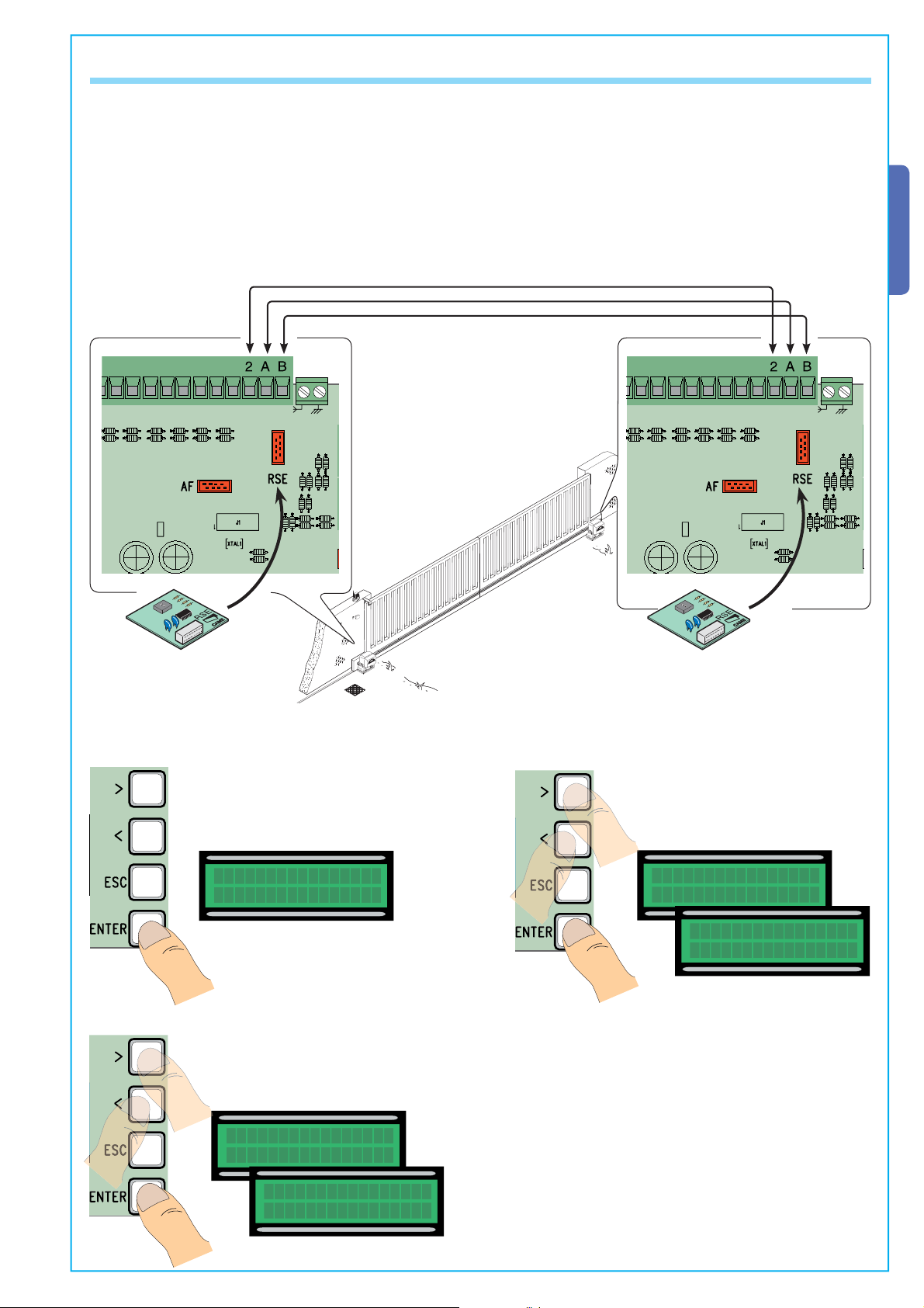
7.14 Net address
The “NET address” function is set when connecting two paired operators.
Connect the two cards using the (2-A-B) terminals and insert the RSE cards into both.
On the “MASTER” card you have selected, make all of the required electrical connections and set the functions and adjustments
(see specific paragraphs).
If the system is fitted with sensitive edges on both gate leaves, carry out the electrical connections on (C7/C8) also for the “SLAVE”
card.
In the event that the “Maintained action” function is activated, set it to (ON) on both of the cards and deactivate (OFF) the “Automatic Closing” function on both.
If you wish to activate the “Automatic Closing” function, select is on both of the cards.
ENGLISH
RSE card
1) On the Master card.
From the Calibration Menu, select
“NET address” and press ENTER.
NET address
Þß
Disabled
RSE card
2) Select “Master” and press ENTER
to confirm the calibration.
NET address
Þß
Disabled
NET address
Þß
Master
The data and information shown in this dialogue may be changed by Came Cancelli Automatici S.p.A. at any time without prior warning.
3) Select “Slave” for another card.
NET address
Þß
Disabled
NET address
Þß
Slave
29
Page 30
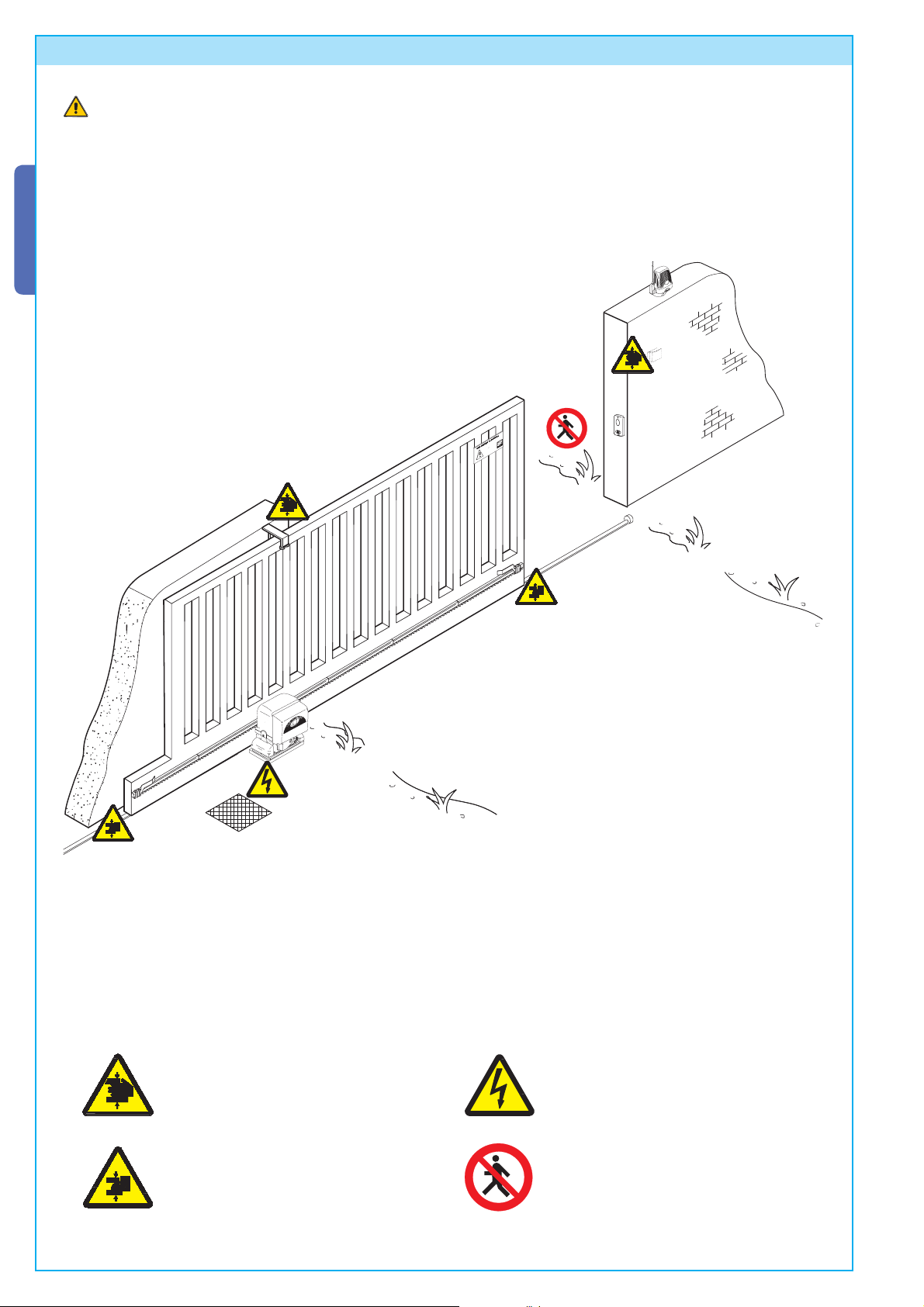
8 Safety instructions
Important safety instructions
This product must only be employed for its originally intended use. Any other use is wrong and potentially dangerous. The
manufacturer cannot be held liable for any damages resulting from wrongful, erroneous or negligent uses.
Avoid working close to the hinges or other moving mechanical parts. Stay out of the opening/closing arc when operator is in
motion.
Do not exercise force against the motion of the operator as this could result in potentially dangerous situations.
ENGLISH
Do not allow children to play or loiter within the opening/closing arc of the operator. Keep remote controls and any other command
device out the reach of children, to prevent operator from being activated by accident.
In the event of anomalous behaviour, stop using the operator immediately.
Danger of crushing hands
Danger! High voltage
The data and information shown in this dialogue may be changed by Came Cancelli Automatici S.p.A. at any time without prior warning.
30
Danger of crushing feet
No transit during operation
Page 31

9 Maintenance
9.1 Periodic maintenance
Periodic maintenance to be carried out by the end-user is as follows: wipe clean the glass surface of the photocells;
check that the safety devices work properly; remove any obstructions.
We suggest checking the state of lubrication and tightness of the anchoring screws on the operator.
-To check the efficiency of the safety devices, move an object in front of the photocells when gate is closing. If the operator
inverts the motion or stops, the photocells are working properly.
This is the only maintenance procedure to be carried out with the power source connected.
-Before performing any maintenance procedures, cut off the main power, to prevent possible accidents due to gate movement.
-To clean the photocells use a water dampened cloth. Do not use solvents or other chemical products which may ruin the
devices.
-In the event of any strange vibrations or squeaking, lubricate the joints with grease, as shown in the diagram.
ENGLISH
-Make sure there are no plants within the photocell’s beam, and that the gate motion is free of any obstacles.
9.2 Trouble shooting
MALFUNCTIONS POSSIBLE CAUSES CHECK AND REMEDIES
The gate will not
open nor close
The data and information shown in this dialogue may be changed by Came Cancelli Automatici S.p.A. at any time without prior warning.
The gate opens
but will not close
The gate closes
but will not open
• There is no power
• The gearmotor is in release mode and the release door is open
• The transmitter’s batteries are run down
• The transmitter is broken
• The stop button is either stuck or broken
• The opening/closing button or the key selector are stuck
• Fhotocells in partial stop mode
• The photocells are engaged
• Check that the power is up
• Call assistance
• Replace batteries
• Call assistance
• Call assistance
• Call assistance
• Call assistance
• Chec k t hat photocells are clea n a nd
in good working order
• Sensitive edge triggered
• Call assistance
• Sensitive edge triggered • Call assistance
The flasher does
not work
• The bulb is burnt • Call assistance
31
Page 32

Periodic maintenance log for end-user (every 6 moths)
ENGLISH
Date Notes
Signature
9.3 Extra-ordinary maintenance
The following table serves to note down any extraordinary maintenance, repairs or improvements performed by specialised firms.
N.B.: Any extraordinary maintenance must be performed by specialised technicians.
Extra-ordinary maintenance log
Installer’s stamp Operator name
Date of job
Technician’s signature
Requester’s signature
Job performed________________________________________________________________________________________
__________________________________________________________________________________________________
Installer’s stamp Operator name
Date of job
Technician’s signature
Requester’s signature
Job performed________________________________________________________________________________________
__________________________________________________________________________________________________
The data and information shown in this dialogue may be changed by Came Cancelli Automatici S.p.A. at any time without prior warning.
Installer’s stamp Operator name
Date of job
Technician’s signature
Requester’s signature
Job performed________________________________________________________________________________________
__________________________________________________________________________________________________
32
Page 33

Installer’s stamp Operator name
Date of job
Technician’s signature
Requester’s signature
Job performed________________________________________________________________________________________
__________________________________________________________________________________________________
Installer’s stamp Operator name
Date of job
Technician’s signature
Requester’s signature
Job performed________________________________________________________________________________________
__________________________________________________________________________________________________
10 Phasing out and disposal
CAME CANCELLI AUTOMATICI S.p.A. employs a UNI EN ISO 14001 certified and compliant environmental protection system at its plants, to ensure that environmental safeguarding.
We ask you to keep protecting the environment, as CAME deems it to be one of the fundamental points of its market operations
strategies, by simply following these brief guidelines when disposing:
ENGLISH
DISPOSING THE PACKING MATERIALS
The packing components (cardboard, plastic, etc.) are solid urban waste and may be disposed of without any particular difficulty,
by simply separating them so that they can be recycled.
Before actions it is always advisable to check the pertinent legislation where installation will take place.
DO NOT DISPOSE OF IN NATURE!
DISPOSING OF THE PRODUCT
Our products are made using different types of materials. The majority of them (aluminium, plastic, iron, electric cables) can be
considered to be solid urban waste. They may be recycled at authorised firms.
Other components (electrical circuit board, remote control batteries etc.) may contain hazardous waste.
They must, thus, be removed and turned in to licensed firms for their disposal.
Before acting always check the local laws on the matter.
DO NOT DISPOSE OF IN NATURE!
11 Conformity declaration
MANUFACTURER’S DECLARATION OF CONFORMITY
CAME Cancelli Automatici S.p.A.
via Martiri della Libertà, 15
The data and information shown in this dialogue may be changed by Came Cancelli Automatici S.p.A. at any time without prior warning.
31030 Dosson di Casier - Treviso - ITALY
tel (+39) 0422 4940 - fax (+39) 0422 4941
internet: www.came.it - e-mail: info@came.it
Declares under its own responsibility that the equipments for automatic garage doors and gates listed below:
Pursuant annex II B of the Machinery Directive 98/37/EC
Do not use the equipment specifi ed here above, before completing the full installation
IMPORTANT WARNING!
In full compliance with the Machinery Directive 98/37/EC
BX-10
… comply with the National Law related to the following European Directives and to the applicable parts of the
following Standards.
98/37/CE - 98/79/CE M
2004/108/CE ELECTROMAGNETIC COMPATIBILITY DIRECTIVE
2006/95/CE LOW VOLTAGE DIRECTIVE
89/106/CEE CONSTRUCTION PRODUCTS DIRECTIVE
EN 13241-1 EN 12635 EN 61000-6-2
EN 12453 EN 12978 EN 61000-6-3
EN 12445 EN 60335-1 EN 60204-1
Reference code to request a true copy of the original: DDF B EN B001c
ACHINERY DIRECTIVE
MANAGING DIRECTOR
Mr. Andrea Menuzzo
33
Page 34

CAME UNITED KINGDOM LTD
UNIT 3, ORCHARD BUSINESS PARK
TOWN STREET, SANDIACRE
NOTTINGHAM - NG10 5BP - U.K .
Tel - 0044 115 9210430
Fax - 0044 115 9210431
Cod. 119BU57 ver. 0.1 09/07 © CAME cancelli automatici s.p.a.
 Loading...