

Camden Door Controls CV-930-20-CH, CV-930-20-RD, CV-930-20-SL, CV-930-20-WH Installation Instructions
Page 1
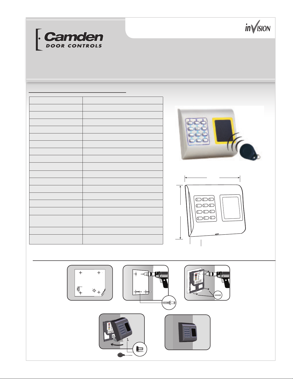
Specifications
CV-930-920 Series
Installation Instructions
Technology
Authentication
Proximity Reading Type
Reading Distance
Interface
Cable Distance
PIN Code Length
Panel Connection
Green and Red LED
Orange LED
Buzzer
Tamper
Consumption
IP Rating
Power Supply
Operating Temperature
Dimensions
Housing
Color
Keypad and Proximity (125 KHz, EM)
PIN Code, Card, PIN Code or/and Card
AWID/HID
2 to 5cm
Wiegand 26, 30, 34, 40bit; Clock & Data
50m (264’)
1- 8 Digits
Cable, 1m (3’)
Externally Controlled
Idle mode
Yes
Yes
Max. 100mA
65
12V DC
5°F to +140°F (-15°C to +60°C)
3 15/16” W x 3 11/16” H x 1 3/16” D
(100m x 94m x 30m)
Moulded Aluminium
Silver, Red, Charcoal, Grey, White
3 ⁄”
(94mm)
1 ⁄”
(30mm)
3 ⁄”
(100mm)
Mounting
1.
Ø6.0
Cable
m
m
0
3
4.
2.
5.
Page 1 to 4
3.
Page 2
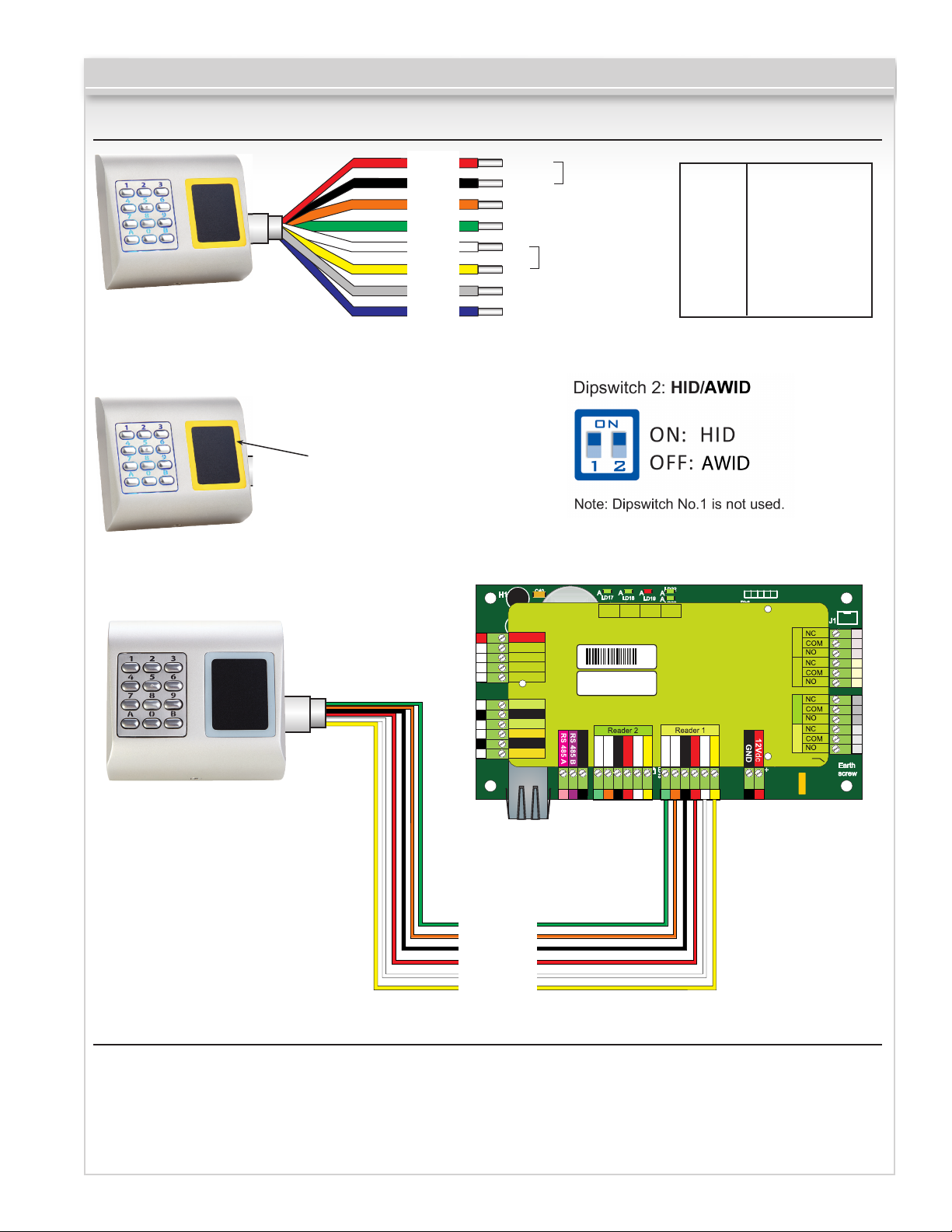
Wiring
CV-930-920 Series Installation Instructions
Red
Black
Orange
Green
White
Yellow
Gray
Blue
Tricolor LED
(Red, Green, Orange)
50m. max
12V DC
GND
LR-
LG-
D0
D1
Tamper
Tamper
H1
R62
12V
FUSE2
12Vdc Out
R7
IN1
+
Free In 1 +
IC12
IN1
-
Free In 1 -
IN2
+
IC2
Free In 2 +
IN2
-
Free In 2 -
R6
R50
R54
PB1
Exit Button1
U1
gnd gnd
GND
PB2
Exit Button2
LD21
R18
Door Sensor1
A
LD20
A
GND
DS2DS1
Door Sensor2
TCP/IP
C40
IC15
TAS1
C5
R53
R15
C3
C34
R10
R49
L3
R25
R24
R22
IC6
U4
POWER SUPPLY
LED Red -
LED Green -
WIEGAND
A
A
LD17
LD18
R5
C4
Tx
Rx
IC1
BAT
IC11
R38
R34
Ser No: 11-04-16-013
X3
Mac: 00-04-A3-16-90-D
L10
L11
ZD6
GND
C18
gnd
BA
C42
IC5
ZD5
R17
X1
R16
C6
C33
R9
Free Led 2
Free Led 1
R55
R46
AAA
LD14
LD16
led2led1
ZD4
R14
ZD3
gnd
L8
GND
R3
R4
L9
R37
R20
R19
C1
R11
12V out
IC1
+12VDC
GND
Tamper
Tamper
LG-
LRD1
D0
LD22
A
A
LD19
A
LD23
R28
R23
R21
D10
System
Busy
OK
L4
C41
C15
C13
C44
RoHS
C43
C2
U5
C32
FUSE1
R45
IC8
D0
D1
A
C29
D1D012V
Free Led 1
R47
LD15
LD13
L6
Free Led 2
ZD1
R1
R13
R2
ZD2
L7
led2led1
IC3
gnd
GND
C12
C27
12V out
IC7
D0
C28
L5
9-14V DC
Ground
Tamper Switch (NO)
Tamper Switch (NO)
Green LED Red LED Data 1
Data 0
Rb6
C45
R48
D5
R36
RX4
RX3
ICN1
D2
C16
D3
L2
ICN2
D1
D13
gnd
12V
D1D012V
LD9
LD8
R33 R35
LD6
R32
LD5
Free Out 1 Free Out 2
Door 1 Door 2
Earth
Fuse
RE4RE2
RE1 RE3
J1
COM
NC3NO3 NC4NO4
COM
COM
NC1NO1 NC2NO2
COM
Earth
screw
A
A
A
A
Redefining Master Code
1. Disconnect Power
2. Press and hold “A” and reconnect Power.
3. Hold the “A” Key for at least 3 seconds.
Green
Orange
Black
Red
White
Yellow
Page 2 to 4
LG-
LR-
GND
+12V
D0
D1
Page 3

CV-930-920 Series Installation Instructions
Enter “Master Code” B + 000000
No
Validation OK?
Yes
1 small beep + 1 long beep + Orange LED is ‘ON’
Error Beep
(3 short beeps)
Change
Master Code
1
Enter New
Master Code
Press 6 Digits
Select Type of
1
Wiegand
Wiegand
26bit
30bit
Direct Menu
Exit
Wiegand
2
2
Wiegand
34bit
Select Output
1 2
Single
Wiegand
3
Wiegand
40bit
Protocol
Double
Wiegand
4
3
3
Clock &
Data
PIN Code
0
for any length
with “A”
in the end
Length
4
Only
PIN CODE
1 - 8
for lengths
between
1 to 8 digits
Entry Mode
5
1 2
Only
Card
Press “A” to validate
and exit the menu
(orange LED OFF)
Entering the Menu is always done with B + 000000 if the
Master Code is not changed.
Submenu 1 - Change Master Code. The Master Code
must be 6 digits. After enrolling new Master Code the
CV-930-20 automatically exits the Menu and the new master
code must be typed to enter the menu.
Submenu 2 - Select Type of Wiegand. With this
the Keypad can be adjusted to send 4 different Wiegand
Outputs. The Wiegand selected must be the same as the
controller’s Wiegand Input that the CV-930-20 Keypad is
being connected to. Example: If you use a controller that
recognizes Wiegand 34bit, then enter the menu of CV-930-20,
press 2, then press 3.
Submenu 3 - Select Output Protocol. The Keypad
can send the Code by different Protocols. Use “Single
Wiegand” when connected to third party controllers. When
“Single Wiegand” is selected, what is typed on the Keypad
is sent as a Wiegand Number. Use Double Wiegand that
connected to CV-350, use Clock & Data when connected to
controller with Clock & Data input.
Submenu 4 - PIN Code Length. If “0” is selected, then
any PIN Code with any length can be sent, but the PIN Code
must be followed with “A” for conrmation( ex. 123 + A).
If 1 to 8 is selected the PIN Code length is determinated by
the number selected.
Submenu 5 - Entry Mode. “Only PIN Code” is disabling
the proximity and CV-930-20 works as a keypad only. “Only
Site Code
Length
7
3
Card and
PIN
Code
4
Card or
PIN
Code
Presets
1 2
No Site
Code
Site Code
between
0 to 15
3
Site Code
between
0 to 255
6
1 2
Wiegand
Wiegand
26bit
normal
34bit
normal
Card” is disabling the Keypad and the CV-930-20 works as
a Proximity Reader. “Card and PIN Code” denes double
security, both the Card and PIN Code is required for the
Wiegand to be sent. “Card or PIN Code” enables normal
operation.
Submenu 6 - Presets. The Presets are a set of
preprogrammed parameters for easy programming.
6-1 “Wiegand 26bit Normal” - Type: Wiegand 26bit;
Output: Single Wiegand; PIN Length: 4 digits;
Entry Mode: Card or PIN Code
6-2 “Wiegand 34bit Normal” - Type: Wiegand 34bit;
Output: Single Wiegand; PIN Length: 4 digits;
Entry Mode: Card or PIN Code
6-3 “Wiegand 34bit CV-350 Mode” - Type: Wiegand
34bit; Output: Double Wiegand; PIN Length: 4 digits;
Entry Mode: Card or PIN Code
6-4 “Wiegand 26bit CV-350 Mode” - Type: Wiegand
26bit; Output: Double Wiegand; PIN Length: 4 digits;
Entry Mode: Card or PIN Code
Submenu 7 - Site Code Length. Set the code length
sent to Host. Default is “0”. To be used only in specic cases.
Submenu 8 - Enter Site Code. Put the site code always
in 5 digit format (ex. 00170).
Submenu 9 - Backlight. Turns ON/OFF the backlight.
3
Wiegand
34bit
EWS
4
Wiegand
26bit
EWS
4
Site Code
between
0 to 65535
Enter Site
Backlight
Code
8
5 digits
Backlight
9
0 1
Backlight
OFF
ON
Page 3 to 4
Page 4

Connecting CV-930-20 to
CV-350 controller
When CV-930-20 is connected to the CV-350 Controller,
settings must be done in the CAMS Software and in the
CV-930-20 Keypad.
Example:
Create a User to access with Card or PIN Code. The Card
Number is 8744987 and the PIN Code 12345.
Settings in the CAMS Software
1. In the CAMS Software, right click on the Reader and
select properties. In the Properties window select for
Type: “CV-930-20” (1.1)
2. Select Entry Mode (Card AND Keycode) (1.2)
3. Select the Wiegand 26bit (1.3)
4. Press Save & Exit. In the event window a conrmation
message will appear as shown in g.2
5. Adjust the PIN Length. Go to Settings/ System
parameters. For Keycode length select 5 digits. (g3)
6. Go To Users Menu and select the user. In the Field
User ID (Card Number) write 8744987. In the Field
”Keycode” write the PIN Code 12345. Save the User.
(g.4)
CV-930-920 Series Installation Instructions
Fig.2
Settings in the LCS
1. Enter the Menu of CV-930-20. Press B+000000.
2. Press 6, press 4. The Preset, programs the
CV-930-20 Keypad to work with CV-350 controller in
Wiegand 26bit.
3. Adjust the PIN Length. Press 4, then press 5.
4. Press 5, then press 3 to select the double security
entry mode.
Present the Card then type the PIN Code and access will
be granted.
Questions? Call us toll-free at 1-877-226-3369
Fig.3
Fig.4
Push Buttons Keypads Strikes Magnetic Locks Key Switches Relays & Timers Access Control
5502 Timberlea Blvd.,
Mississauga, ON Canada
L4W 2T7
www.camdencontrols.com
Toll Free: 1.877.226.3369
Page 4 to 4
File: CV-930-20 Series
Installation Instructions.innd
Revision: 06/05/2015
Part No.: 40-82b176
 Loading...