

Page 1
M-PROX2
Installation Instructions
Section 1
General Description
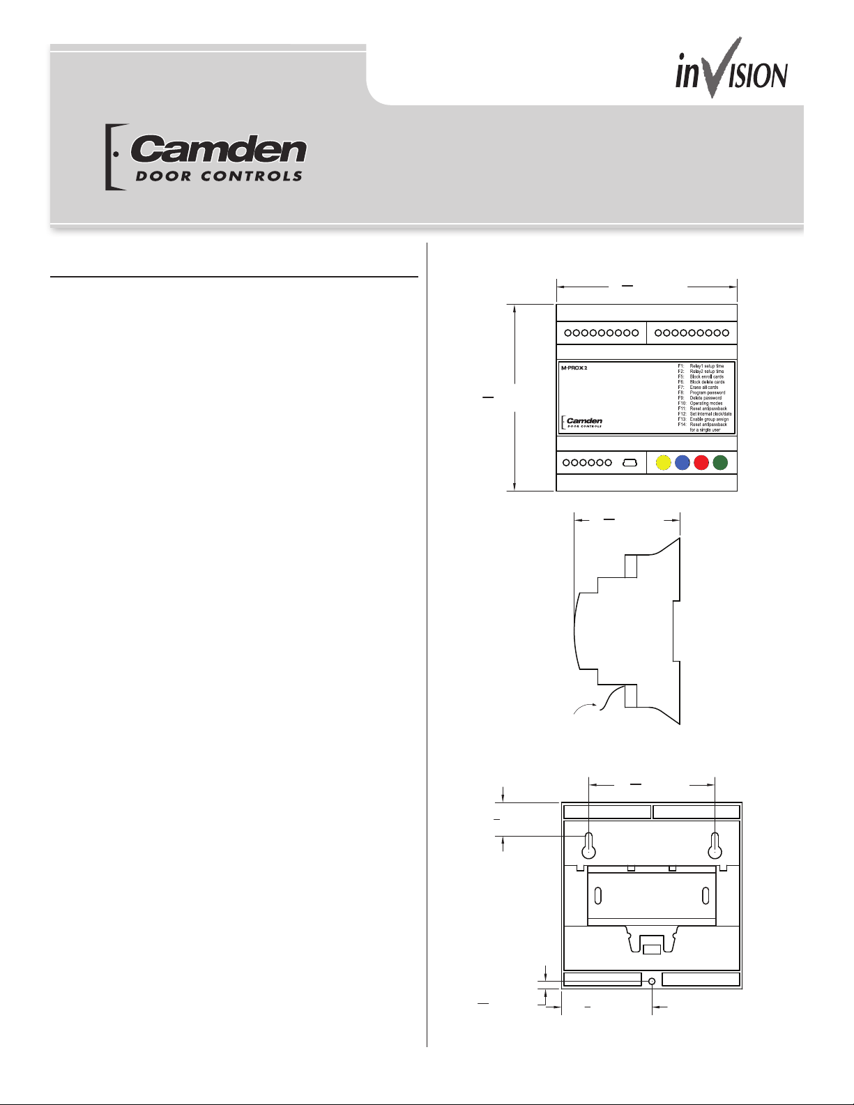
The M-PROX2 (CV-602) is a 2 door access control system.
It has 2 inputs for HID/AWID proximity readers, 2 Form C relay
outputs for connection to electried or magnetic locks for door
access control, and can accept up to 2,000 user codes.
System features include:
• 12/24 V AC/DC operation
• 2,000 user codes
• 2 Wiegand inputs
• Request-to Exit
• 2 Form C relay outputs, 5A @ 30V DC
• Timed relay output
• Individual/batch card enrollment
• Individual/batch card deletion
• Group assignment
• 26, 34 and 37 bit wiegand compatible
• Operating modes: full, hard or timed anti passback
• Password protection
• USB port for PC interface
• Audit trail
• Scheduling – daily, weekly, holidays
The M-PROX2 may also be programmed locally via the
4 button and 4 digit LED display. Features available for local
programming are:
• Programming new codes into memory
• Deleting single codes from memory
• Selecting bi-stable or timed operation mode independently
for each relay
• Setting the relay activation time
• Setting the internal clock
181716151413121110
5
"
4
[110mm]
16
1920212223
Pull paper tab to engage
the backup battery
3
"
[22mm]
4
2
24
7
16
3
"
4
16
"
[62mm]
15
2
16
[106mm]
987654321
"
[74mm]
16
3
"
[4.5mm]
1
2
8
"
[53mm]
Page 1 of 16
Page 2
M-PROX2 Installation Instructions
Section 2
Installation
The M-PROX2 is housed in a plastic enclosure suitable for
indoor installations. It is compatible with standard 35 x 7.5
mm DIN rails or the provided mounting holes may be used.
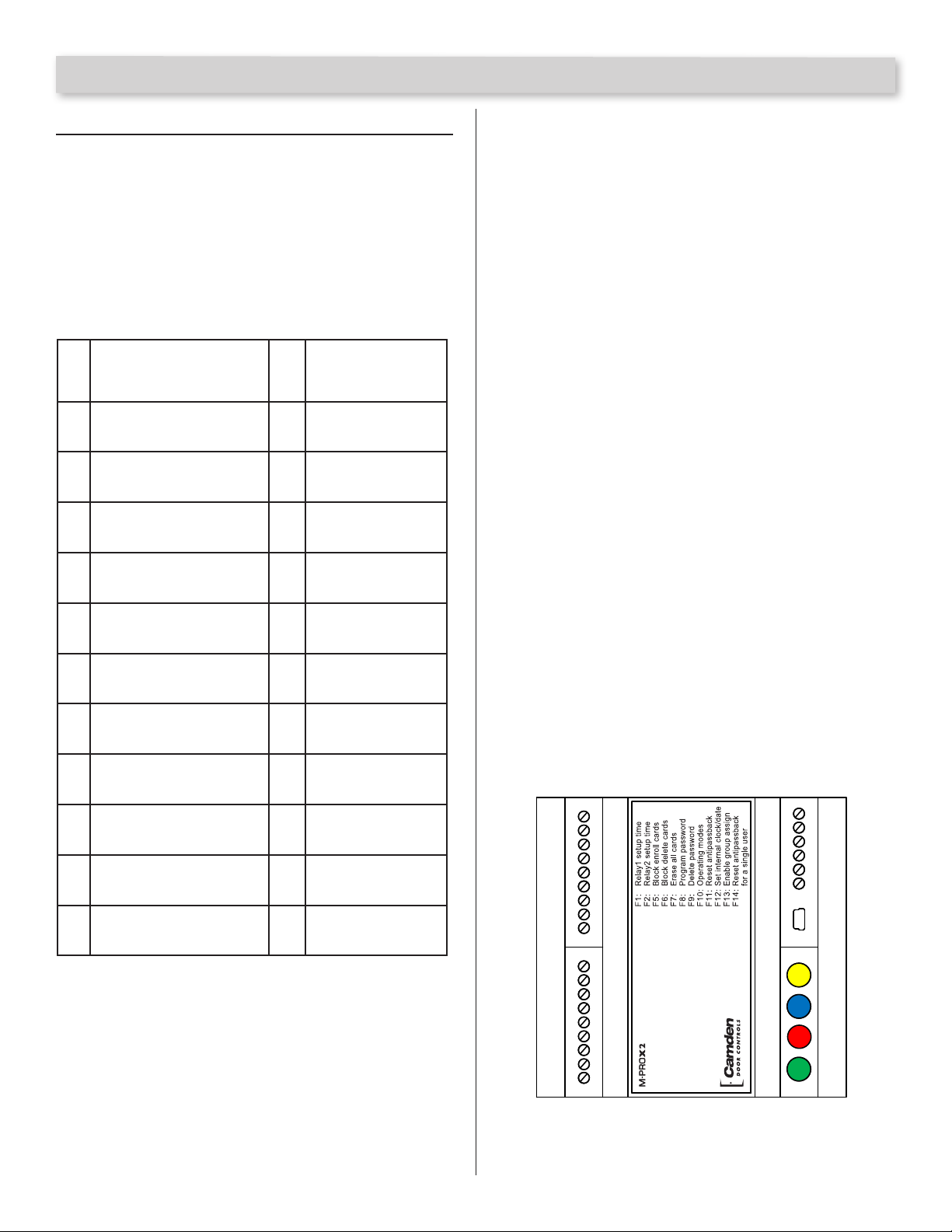
Wiring
Connect your 12/24V AC/DC positive output to the 12-24 V
input. Connect your 12/24V AC/DC common output to the
ground input. Connect the proximity readers as shown:
Port 2: relay contact N.C.
1
Port 2: relay common
2
Port 2: relay contact N.O.
3
Port 2: enable
4
Port 2: activate
5
GROUND
6
Port 2: (DATA1)
7
Port 2: (DATA0)
8
Port 2: power for reader
9
(9Vdc)
Port 1: relay contact N.C.
10
Port 1: relay common
11
Port 1: relay contact N.O.
12
Port 1: enable
13
Port 1: activate
14
GROUND
15
Port 1: (DATA1)
16
Port 1: (DATA0)
17
Port 1: power reader
18
supply (9Vdc)
Antenna
19
Antenna braid
20
Serial line (RS485)
21
Serial line (RS485)
22
Power supply,
23
+ 12-24Vac/dc
Power supply,
24
- 12-24Vac/dc
12 – 24 V and Ground
Power input terminals allow for 12 to 24V AC/DC.
Data Link
Factory Use Only
Antenna and Antenna Shield
Factory Use Only.
9V DC Out
Output power for the wiegand reader.
DATA 0 and DATA 1
These are the wiegand data inputs. Connect the wiegand
reader/keypad data lines to these inputs.
Activate (Request to Exit)
Activate may be connected to push buttons mounted on the
door or to REX Sensors mounted near the door. The push
buttons or REX Sensor normally open dry outputs are connected
across the Activate and Ground. A contact closure across
Activate and Ground will cause the M-PROX2 to grant access
through the appropriate door.
Enable
The Enable input is used to enable the output relay. A connection
to Ground will enable the output relay. The M-PROX2 is shipped
with a jumper installed, enabling the output relay at all times.
This jumper can be replaced with a Dry contact across the
Enable and Ground pins from an external control device,
providing hardware controlled access.
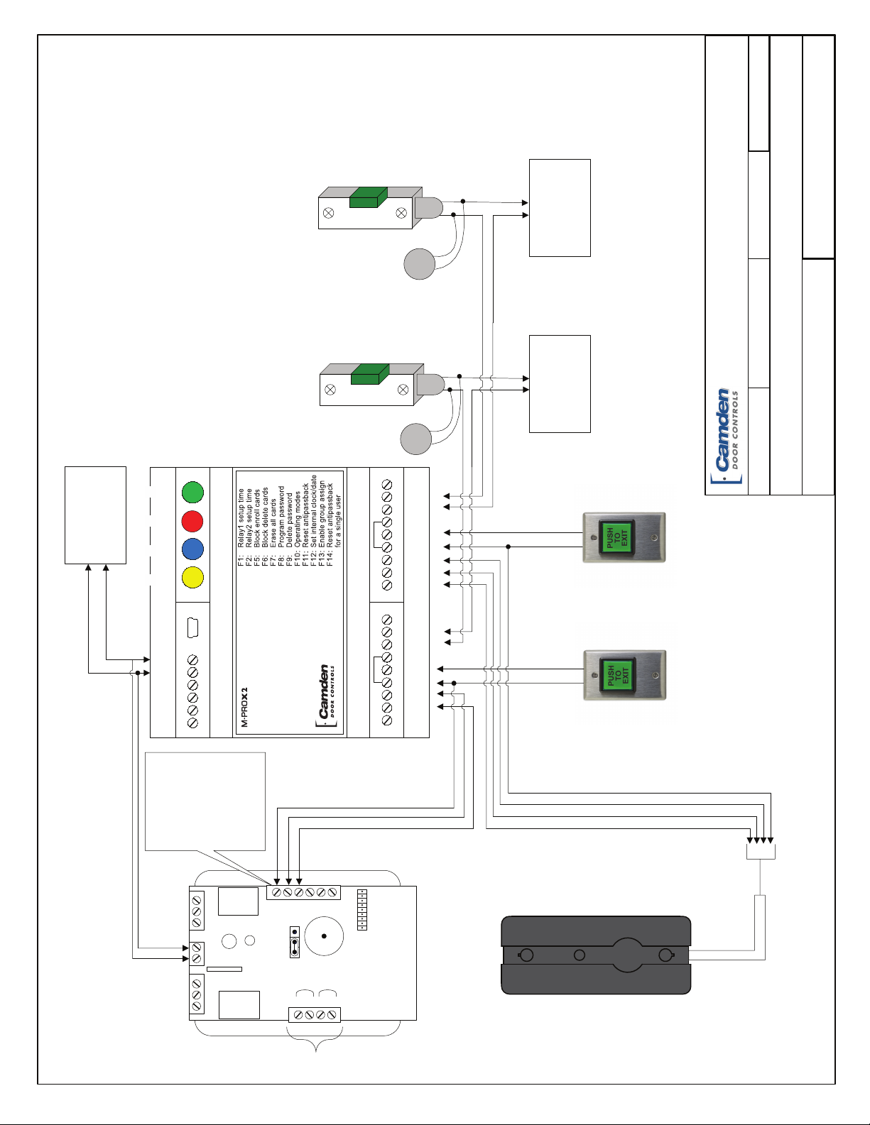
Relay Outputs
These are the door control relays. Connect these relay outputs
to the magnetic lock or electric strike as required.
NOTE: The M-PROX2 does not provide power on these outputs
for the door locking devices. A separate power supply must be
used to provide power to the locking devices. Please refer to
Drawing:
9V dc out
data 0
data 1
ground
acvate
enable
NO
9V dc out
data 0
data 1
ground
acvate
enable
NO
NC
1
2
3
4
5
6
7
C
8
9
NC
10
11
12
13
14
15
16
C
17
18
19
20
21
22
23
24
12-24V
ground
USB
FUNCTION
DECREASE
INCREASE
VALVE
Page 2 of 16
MProx2 Pinout Diagram
Page 3
5502 Timberlea Blvd
Mississauga, Ontario
L4W 2T7
REVISED: 10/10/2014
MProx2 Diagram 1.vsd
Power Supply
12/24V AC/DC
DATE: 10/10/2014
MOV
Wire supplied
MOV directly to
strike or magnet
FILENAME:
MProx2 Wiring Diagram
Camden Door Controls
reader. (2) CV-7500's or (2) CM-120 keypads could be used.
NOTES:
for programming instrucons.
1. Diagram shows a CM-120Wv2 Keypad with a CV-7500 AWID proximity
2. The CM-120 keypad must be in Wiegand Mode. Refer to Appendix A
Door #2 Door #1
Power Supply
12/24V AC/DC
DRAWING No:
Wire supplied
VALVE
INCREASE
Power Supply
12/24V AC/DC
DECREASE
FUNCTION
USB
Wiegand
Interface
ground
12-24V
6 - GND
5 - DATA 1
4 - DATA 0
3 - Red LED
2 - Green LED
1 - Buzzer
MOV
MOV directly to
strike or magnet
NC
C
NO
enable
acvate
ground
data
1
data 0
9V dc out
NC
C
NO
enable
acvate
ground
data 1
data 0
9V dc out
CM-30 CM-30
To
Door #1
Request
To
Door #2
Request
SCALE: NONE DRAWN BY: JLewis
Exit
Exit
1
2
3
1
2
12V Power
1
2
3
Not Used Not Used
123
364
REX
Input
123
Not
152
Buzzer
Door
Contact
Input
4
Used
CM-120Wv2
Rear View
CV-7500
Page 3 of 16
Page 4
M-PROX2 Installation Instructions
Section 3
Programming
Local setup and Configuration
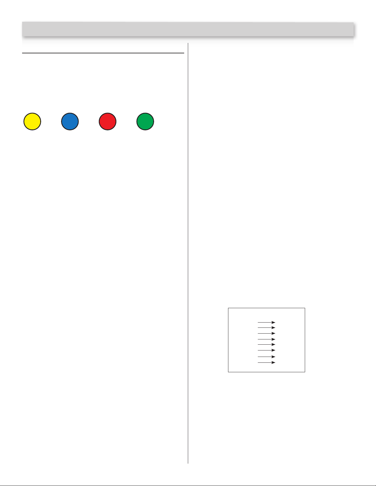
The M-PROX2 is easily programmed locally via 4 buttons and
a 4 digit display. User codes may be enrolled individually or in
groups. The buttons are:
Yellow RedBlue Green
FUN DEC INC VAL
FUN – [ Function Button ]
Allows you to select the function to program.
DEC – [ Decrease Button ]
Moves down the list of available options.
INC – [ Increase Button ]
Moves up the list of available options.
VAL – [ Value Button ]
Changes the value of the selected function.
Also used as a conrmation button.
Enter Programming Mode
Press the Red and Blue together and release.
Functions
There are 12 available functions when programming the
M-PROX2. They are:
F1 – Relay 1 Setup time – Set the ON time for Relay 1
Press the Red and Blue together and release to enter
programming mode
Press Yellow. Use the Red and Blue to select F01.
Press Green to conrm and exit.
Press Red or Blue to increase or decrease the
Relay ON time.
Press Green to conrm and exit.
F2 – Relay 2 Setup Time – Set the ON time for Relay 2
Press the Red and Blue together and release to enter
programming mode
Press Yellow. Use the Red and Blue to select F02.
Press Green to conrm and exit.
Press Red or Blue to increase or decrease the
Relay ON time.
Press Green to conrm and exit.
F3 – Reserved
F4 - Reserved
F5 – Block Enroll Cards – Enroll cards in batches/groups
Access programming mode by pressing keys Red+Blue.
Press the Yellow key to access the function selection menu.
Select function F5 by pressing keys Red and Blue
Conrm by pressing the Green key. The rst memory slot
location to be programmed will now appear, default value
being 0001. Only the rst decimal point to the left will appear
indicating that the initial location is being selected.
Select memory location by pressing keys Red and Blue, and
conrm by pressing the Green key.
The memory location to be programmed will now appear.
The value shown is the one which has been previously selected
as the initial location so that only a value greater than this can
be selected by pressing keys Red and Blue.
The last decimal point to the right will now appear indicating
that the nal location is being selected.
After selection of the nal memory location, conrm by pressing
the Green key.
If group association is enabled, the display will show GR00.
Select the group by pressing either Red and Blue. If GR00 is
selected, then no group will be assigned.
Press the VAL (Green) button to conrm your settings. The
M-PROX2 is now ready to accept the rst code to be enrolled.
Four decimal points are displayed. Present your rst card/keytag
to the reader. Once the code has been received, all subsequent
memory locations up to the nal one are programmed with
codes calculated from the starting code plus one. During the
programming operation the four decimal points will blink. If a
code to be programmed already exists, then the operation is
aborted and ERR is displayed.
Example: initial location = 120, final location = 127,
received code = 112233
Location Code
120
121
122
123
124
125
126
127
112233
112234
112235
112236
112237
112238
112239
112240
Once all locations having been lled with the codes, the system
will return to the function menu.
F6 – Block Delete Cards – Delete cards in batches/groups
Access programming mode by pressing keys Red+Blue.
Press the Yellow key to access the function selection
menu.
Select function F6 by pressing keys Red and Blue.
Page 4 of 16
Page 5

M-PROX2 Installation Instructions
Conrm by pressing the Green key. Request of the rst
location to be deleted (that is, the default value 0001)
will now appear. Only the rst decimal point to the left
will appear indicating that the initial location is being
selected.
Select location by pressing keys Red and Blue, and
conrm by pressing the Green key.
Request of nal location to be deleted will now appear.
The value shown is the one which has been previously
selected as the initial location so that only a value
greater than this can be selected by pressing keys
Red and Blue. The last decimal point to the right will now
appear indicating that the nal location is being selected.
After having selected the nal location, conrm by
pressing the Green key; the letter -C- will now appear on
the left-hand side of the display.
Press the Green key again to conrm. The M-PROX2 will
now automatically delete all the codes stored in the set
of programmed locations.
Press keys Red and Blue at the same time to exit
programming
Upon deletion being completed, system will return to
the function selection menu.
F7 – Erase all Cards – Delete all cards from the system
Deletion of all codes avoids having to scroll all locations
and having to delete one code at a time in case of
memory having to be fully cleared.
Access programming mode by pressing keys Red+Blue.
Press the Yellow key to access the function selection menu.
Select function F7 by pressing keys Red and Blue.
Conrm by pressing the Green key. The letter C will appear
on the left side of the display.
Conrm again by pressing the Green key. The M-PROX2
will fully delete the code area only. All other stored
parameters (schedules, Holidays, etc.) will remain
unaltered.
Press keys Red and Blue at the same time to exit
programming.
Upon deletion being completed, system will return to the
function selection menu.
F8 – Program Password
Access programming mode by pressing keys Red + Blue.
Press the Yellow key to access the function selection menu.
Select function F8 by pressing keys Red and Blue and
conrm by pressing the Green key.
The letter P will appear on the left side of the display.
Digit a sequence of six keys within 10 seconds.
Note: Store your password in a secure place for retrieval
later. If your password is lost, a full reset will have to be
performed and all data will be lost.
Upon the full sequence of six keys having been
completed, the function selection menu will reappear on
the display.
Press keys Red and Blue at the same time to exit
programming
Failure to complete sequence within 10 seconds will
abort password entry. This also avoids entry of incorrect
passwords in case of any doubts as to the sequence to be
entered or erroneous pressing of any key.
The password is stored in EEPROM and is requested
whenever Red+Blue are pressed to access programming
mode starting from the stand-by status (displays being
off). In this case:
The letter P appears on the left side of the display. Digit
the sequence of six keys corresponding to the password.
Upon the 6-key sequence being completed,
programming mode is accessed. If sequence is
erroneous, the displays will go off.
Upon programming mode being accessed, any resident
password may be deleted or replaced with a new one
repeating the operation.
Note: To remove a password which has been forgotten,
contact system supplier. This requires a full system reset.
F9 – Delete Password – Delete the password
Press Red+Blue to access programming mode:
the password will be requested.
Key in the password.
Press the Yellow key to access the function selection menu.
Select the password entry function F9 by pressing keys
Red and Blue and conrm by pressing key Green: the
password will be requested.
Key in the password.
Password is deleted and will not be requested upon any
subsequent accessing of programming mode.
Press keys Red and Blue at the same time to exit
programming
F10 – Operating Modes – There are 3 operating modes.
1. Full –All cards programmed will activate both Relay
1 and Relay 2 when presented to the Prox reader.
programming mode
2. Pass –Hard anti-passback. Once one of the
two relays is activated, it will not reactivate until
the other relay has been activated.
3. APt – Timed anti-passback. Once one of the relays
has been activated, it can’t be reactivated until the
preset timer has run out.
Page 5 of 16
Page 6

M-PROX2 Installation Instructions
Press keys Red and Blue at the same time
Press key Yellow to access the select functions menu
Using keys Red and Blue select function F10
Conrm the selection with Green: the display shows the
current value of the mode.
Using keys Red and Blue select mode Full, Half or Pass.
Conrm with key Green: the display returns to selecting
functions and the new mode is active.
Press keys Red and Blue at the same time to exit
programming.
F11 – Reset Antipassback
Access programming mode by pressing keys Red+Blue.
Press the Yellow key to access the function selection menu.
Select function F11 by pressing keys Red and Blue.
Conrm by pressing the Green key. The letter O will appear
on the left side of the display.
Conrm again by pressing the Green key. The state of all
the users will be set to idle (the rst activation is enabled
on every direction).
Press keys Red and Blue at the same time to exit
programming.
F12 – Set Internal Clock/Date – Set the time and date for
the audit log
Access programming mode by pressing keys Red+Blue.
Press the Yellow key to access the function selection menu.
Select function F12 by pressing keys Red and Blue.
Conrm by pressing the Green key. The letter H will appear
followed by the actual hours.
Select the value using the Red key.
Conrm by pressing the Green key. The letter M will appear
followed by the actual minutes.
Select the value using the Red key.
Conrm by pressing the Green key. The letter Mo will
appear followed by the actual Month.
Select the value using the Red key.
Conrm by pressing the Green key. DST followed by Y (Yes)
or N (No) will appear.
Select the value using the Red key.
Conrm with key Green: the display returns to selecting
functions and the clock will be set.
Press keys Red and Blue at the same time to exit
programming.
F13 – Enable Group Assign – When enrolling cards in batches,
you have the option to assign groups to the batches. If this
function is disabled, you cannot assign groups to batches.
Simultaneously press keys Red and Blue.
Press key Yellow to access the function selection menu.
Select function F13 by pressing keys Red and Blue.
Conrm selection by pressing the Green key; current
parameter value will appear on the display.
Select the desired value by pressing keys Red and Blue.
(GRPY to enable and GRPn to disable)
Conrm by pressing key Green and the value will be stored.
Press keys Red and Blue to exit from programming mode.
F14 – Reset Antipassback for a single user –
Press keys Red and Blue at the same time.
Press key Yellow to access the select functions menu.
Using keys Red and Blue select function F14.
Conrm the selection with Green: the display shows the
current value location of the rst memorized code.
Use the Red and Blue buttons to select the location to be
reset.
Once the location has been chosen, conrm with Green:
the display shows ”rAPB”.
Conrm with Green: the display shows the location again
and the user is set in Idle state (see previous point). Exit
by pressing Yellow.
Press Red and Blue keys at the same time to exit
programming.
Select the value using the Red key.
Conrm by pressing the Green key. The letter D will appear
followed by the actual Day.
Select the value using the Red key.
Conrm by pressing the Green key. The actual day of the
week will appear.
Select the value using the Red key.
Conrm by pressing the Green key. The letter Y will appear
followed by the actual Year.
Page 6 of 16
Software Manager Programming
The M-PROX2 Software Manager provides advanced
programming functionality. You can set up multiple installation
proles to be saved on your PC.
Installation
1. Windows 7 (32 or 64 bit)
Insert the CD/USB memory stick into your computer.
Page 7

M-PROX2 Installation Instructions
Open the folder on your computer containing the M-PROX2
software. Run Setup.bat.
The system will automatically detect your operating system and
start installing.
Select your language.
Select Next.
When prompted with a Security Warning, select Run.
The software will unpack the installation les start the
setup program.
Select the installation destination or accept the default
and press Next.
Page 7 of 16
Page 8

M-PROX2 Installation Instructions
Select a Program Manager Group or accept the default.
Press Next.
Select Next to start installing the software.
The nal step is a small utility that runs to make nal
conguration changes to support the software. Please allow
this to run. The screen will disappear when it has completed.
Section 4
Operation
1. Starting Camden Software Manager
a) Working Offline
The Camden Software Manager can be used without an
M-PROX2 connected. You can create installations and save
them to be uploaded to an M-PROX2 when ready. When there
is no M-PROX2 connected via USB, the software will only
display 3 menu items. File, Hardware and Utilities.
Select Finish.
i. File
The File Menu is used to create Installations, setup
schedules and proles. Other functions such as
Importing and Exporting databases, creating a
Maintenance schedule are available.
a. Creating an Installation
Multiple installations may be created and then
uploaded to the different M-PROX2 systems when
online. To create an installation, open the Files
Menu and select Installations. From the icons on
the bottom of the window, select New.
Page 8 of 16
Page 9

In the Installations dialog, enter all pertinent information
about the installation. Client details, creation date and
other information required. From the Memory Type pull
down menu, select M-PROX2.
Right-Click in the Groups, Weekly proles, Holiday
proles and Holidays windows to Add/Delete
Groups, proles and Holidays.
Codes: Press this button to add/remove
or view codes.
Adding Codes to an Installation
Select the New Icon.
Enter the Number of Codes. Codes may be entered 1
at a time or in sequential batches.
Enter the First Code
Enter the Start address for the rst code.
Assign a Group.
Type a description
Copy – N/A
Parameters Press this button to set
advanced features of the M-PROX2. Select
Personalized to add a site code. Up to 4
additional site codes may be added if required.
M-PROX2 Installation Instructions
Memory
Personalized
Select this option and enter a site code to force the
M-PROX2 to only function with the assigned Site Code.
Additional site codes are entered in the Extra Site
options. Using the Extra Site Start and Extra Site Stop,
a range of site code may be entered. Alternatively,
Individual site codes may be added using the Extra Site
3 and Extra Site 4 settings.
Advanced Functions
Memory Mode
Full – Anti-pass back is disabled. All users have access to
Relay1 and/or Relay2.
APB – Anti-pass back is enabled. Relay1 is an
Entry relay and Relay2 is the Exit relay. Once Relay
1 has been activated, it cannot be reactivated until
Relay 2 has been activated.
APT – Timed Anti-pass back. After the entry of a user,
he cannot re-enter for X minutes unless, in the
meantime, he exits. The inhibit time eld is displayed to
set the inhibition period in minutes.
Daylight Savings Time
Enable Daylight Savings Time (DST). Select either North
American (USA) or European (EUR) standard.
Use Facility Code
Select this option to enable the MProx2 to look for a
facility code when a card is swiped.
Use REX2 to reset APB
When enabled, a contact closure across pins 5 (Activate)
& 6 (Ground) will reset the status of the Anti-Pass Back
feature.
Relay Weekly Profiles
Relay weekly proles are used to set up schedules
for when Relay 1 and/or Relay 2 will be held open. If
these schedules are set, enabling this option will activate
these schedules.
Page 9 of 16
Page 10

Local Group Programming
This option, when enabled, forces any new users added
to the system to be assigned to a group.
Events View the event log stored from the last
time the M-PROX2 was online.
M-PROX2 Installation Instructions
c. Holiday Dates
Use this dialog to set up Holiday dates like Christmas,
Labor Day, Thanksgiving, etc… These are typical
annual holidays.
Maintenance Allows you to keep a log of
maintenance performed on an installation.
b. Creating Groups
Select Group from the File menu. Press the New icon.
Enter a description for the Group. The group can be
given access to control Relay 1, Relay 2 or both by
selecting the appropriate check boxes. Enable Anti-
passback if required. Select the Weekly and Holiday
proles applicable to the group.
d. Creating Profiles
Weekly Proles are used to setup schedules for access
from Monday to Sunday. Select New from the icons.
Provide a description for the prole. Set up to 2 ‘On’
times for each day.
Page 10 of 16
Page 11

M-PROX2 Installation Instructions
you must rst copy the “pcsys30.mdb” database located in C:\
SWManager. Once you have copied and renamed the database,
press the “…” button, a window is displayed in which you can
select the database to use.
3. Help
This function displays the guide, which can also be
recalled by pressing the button “F1” on th keyboard.
Holiday Proles are used to setup schedules for access
during Holidays as set in the Holiday Dates dialog.
These proles are associated with Group Proles to determine
access schedules during Holidays. Select New from the icons.
Provide a description for the prole. Set up to 2 ‘On’ times for
each day.
NOTE: The Holiday Proles supersede the Weekly Proles.
ii. Hardware
1. Detect Devices
Use this command to detect the M-PROX2 once it is
plugged into the USB port.
iii. Utilities
1. ConvertDB v1.3
2. Options
Language
Set the language for messages and menus.
Serial Port
Select the computer serial port to communicate with
the M-PROX2.
Database
The “Selected database” box shows which database is used to
save installations.
If you want to record the installations on different databases
4. Information About
b) Working Online
i. Installing the Driver
1. The driver is installed during the installation
of the software.
ii. Plugging the M-PROX2 into a USB port
1. Plug the M-PROX2 supplied USB cable into a
spare USB port on the host computer.
The computer will automatically detect and
install the driver.
iii. Determining the COM Port assigned to the
M-Prox2.
1. Open the Computer Control Panel
Page 11 of 16
Page 12

2. Select the System Icon
3. Open the Device Manager
4. Scroll Down to Ports (COM & LPT)
5. Find the entry: USB Serial Port (COMx), where x is
the COM port number.
M-PROX2 Installation Instructions
ii. Enter Cards/keytags
Enter proximity cards or keytags individually or in
groups. It is important to note that when entering a
group of proximity cards or keytags, the Group assigned
will be the same for all selected codes.
Number of codes
Enter the total number of codes for the batch you are
programming. I.e. for 1 code enter 1, for 10 codes
enter 10…etc.
First code
Enter the rst code in the batch. If there is only 1 code,
enter that code.
Star t address
Enter the starting address for the rst code to be
entered in the M-PROX2 memory. Valid entries are
from 1 to 2000.
Group
Assign to a group the batch of codes you are
programming.
Copy
The Copy parameter must be ‘0’ for every new user.
Use this eld to keep track of lost keytags/cards.
6. Select the correct COM port in the Options screen
in the Camden Software Manager.
c) Online Operation
i. Display/Print
Display a list of codes and their parameters stored in
the M-PROX2 memory. Select the Print Icon to print
the list to an available printer on the PC.
Page 12 of 16
iii. Delete Cards/keyfobs
Deletion – Select
The list of the codes is displayed, from where you can
delete one or more of them.
Page 13

Select the codes to be deleted and conrm with Delete.
If you want to select several consecutive codes, hold
the Shift key while you drag the selection with the mouse.
If you want to select non-consecutive codes, select
them while holding the Ctrl key.
Deletion - Total
Performs a complete deletion of all the codes in the
M-PROX2.
iv. Copy
Copy – Module->Database
Reads the contents of the memory module and
allows the transfer of the read codes and the eventual
personalization into the database.
Press the “New” button to create a new installation in
the database and name it then copy the module
displayed into the new installation.
Press the “MM->DB” button to copy the module into
an installation already present in the database. The list
of installations is displayed. Select the installation
in which you want to transfer the codes and press
“OK”. A message is displayed with the option to
overwrite the installation or merge the memory module
with the installation.
Copy – Database to module
With this function you can transfer the codes and any
personalization of one of the database installations to
a memory module.
v. Password
Password – Delete
For deleting the password of a protected memory
module.
Password – Enter
The password is a combination of six colored button.
Once you have protected the module with a password,
this will be required for each operation of code
insertion, code deletion, identier association
or password modication.
vi. Parameters
vii. Events
Events - Download events
Every event present in the M-PROX2 is downloaded
and displayed in a window.
Here you can print the list or save it in the database.
With this operation the events will NOT be erased from
the M-PROX2.
M-PROX2 Installation Instructions
Events - Delete events
Delete all events in the device connected.
viii. AntipassBack
Antipassback - Force all to neutral status
Select this option to force the anti-passback status of
all users to neutral status.
This can be used in case of a lock/gate malfunction to
avoid users being locked inside.
ix. Set Clock
Set the internal M-PROX2 clock using the PC clock.
e. Access Control
The M-PROX2 has a number of functions that can be
used to dene the right of the users.
Every user can be assigned a group authorization
which is dened by:
- Relays activation prole
- Anti-pass back activation
- Weekly prole to allow the user to enter only during
certain hours of the week
- Holiday prole to allow the user to enter only during
certain hours during the holidays
Using SWManager, this can be managed and stored in the
database.
Page 13 of 16
Page 14

Creation of a weekly profile
Select “weekly prole” from the “Files” menu, click on
“New” in the prole list
Use arrow or compile eld to create the prole for each
day of the week in which access can be granted and
then add a name to the prole.
Creation of a holiday profile
Select “Holiday proles” and “New”
The arrows or the eld to create the prole during
which access can be granted, and then add a name
to the prole.
M-PROX2 Installation Instructions
Creation of the group authorization
Each user can be assigned a group authorization which is
dened by:
- Relay activation
- Anti-pass back activation
- Weekly prole to allow the user to enter only during
certain hours each day of the week
- Holiday prole to allow the user to enter only during
certain hours during the holiday
To dene the group authorization, select “Groups” from the
“Files” menu and then on “New”
Assign a description to the group, and then choose the
relay that the user associated to this group can open,
the anti-pass back activation, the weekly and holiday
prole, and then save.
Creation of the holiday dates
Select “Holiday dates” and “New”
Insert the name and the dates of the holiday to be
inserted and check “Recurrent” if the Holiday is to be
repeated each year.
Page 14 of 16
Assign the control access function to the installation
After the creation of the function with the previous entry,
you can add them to the installation desired. Select
“Installation “ from the “Files” menu and double-click on
the desired installation.
Page 15

M-PROX2 Installation Instructions
To add a group, right-click on the group list in the “Access
control functions” and then choose the group to add.
When a group is selected the associated weekly and
Holiday proles are added as well.
To add Holiday dates, right-click on the Holiday dates list
in the “Access control functions” and then choose the
dates to add.
Relay 1 weekly profile, Relay 2 weekly profile
For each relay of the M-PROX2, a weekly prole can
be specied. The relay will remain enabled during the
hour specied in the corresponding prole. User activation
and input REX will open the relay outside the prole.
Appendix A
Interfacing Camden’s CM-120Wv2 Keypad with
MProx Door controllers
The CM-120Wv2 keypad can easily replace the proximity reader
used with the M-PROX2 (CV-602) door controller.
The wiegand protocol output feature of the 120Wv2 keypad is a
very simple feature to activate and utilize for use with any basic
or enterprise level access control system. When programmed,
the keypad will send 26 bit wiegand protocol numbers to an
existing access control system, with or without a facility code
(programmable) when a number with a value between 1 and
65,535 is entered into the key pad. Basically, numbers become
the credential at this door/entry point, and as long as an
individual has been issued a number that is programmed into
the access system data base, or enters the numbers from their
issued credential (card or FOB) they will be granted access
(based on the access group and privilege level associated with
their credential)
Once the keypad wiring is complete, as per the diagram below,
apply power and begin programming. The programming steps to
initiate this feature and associated functions of the feature are
listed below.
The CM-120Wv2 keypad has 26 bit Wiegand output capability
which is compatible with the M-PROX2 Wiegand input. Setting
up the M-PROX2 for use with the CM-120Wv2 keypad is easily
done:
CM-120Wv2 Setup:
1. Program the CM-120Wv2 keypad for Wiegand output.
2. Program a Site Code (if required) into the CM-120Wv2.
(M-PROX2 CV-602 Only).
Programming the Keypad
In our usual convention, commands contained in square
brackets […] represent keys being pressed together. Always
press the * rst, then press the secondary key while holding the
* down. Release the keys together. All other keys are pressed
individually.
[*1] <master code>(default 1234) * - Enter programming mode
[*5] 0 # <set wiegand option> * - Put keypad in wiegand mode
(0= disabled(default), 1=26 bit, 2=26bit+facility code)
[*5] 1# <set facility code> * - Set facility code if required
(Enter facility Code 0-255)
CV-601/602 Setup:
1. Press DEC and INC together to enter programming mode.
2. Use DEC/INC to set the memory location required.
3. On the CM-120Wv2 keypad enter a valid user code and
press *.
4. The memory location will have periods inserted after the
rst 2 numbers. Press Green to accept the programming
and periods are inserted after all 4 numbers.
a. E.g. Memory 0001 => 000.1. VAL => 0.0.0.1.
Additionally, any of our Wiegand output keypads may be
interfaced to the M-PROX2 units in the same way to replace a
proximity reader.
Page 15 of 16
Page 16

M-PROX2 Installation Instructions
VALVE
Power Supply
12/24V AC/DC
INCREASE
DECREASE
FUNCTION
USB
ground
12-24V
NC
C
NO
enable
acvate
ground
data 1
data 0
9V dc out
NC
C
NO
enable
acvate
ground
data 1
data 0
9V dc out
Mississauga, Ontario
L4W 2T7
5502 Timberlea Blvd
REVISED: 10/29/14
CM-120 to MProx2.vsd
DATE: 10/29/14
FILENAME:
Camden Door Controls
Interfacing a CM-120 Keypad to the MProx2
DRAWING N o: JL -CM-12 0_02
SCALE: NONE DRAWN BY: JL
1
2
3
1
2
12V Power
1
2
3
Not Used Not Used
123
364
REX
Input
123
152
Buzzer
V.2
Door
Contact
Input
Rear View
4
CM-120
Not Used
Wiegand
Interface
6 - GND
5 - DATA 1
4 - DATA 0
3 - Red L ED
2 - Gree n LED
1 - Buzz er
Push Buttons Keypads Strikes Magnetic Locks Key Switches Relays & Timers Access Control
DISCOVER THE BEST IN DOOR ACTIVATING
AND LOCKING PRODUCTS!
www.camdencontrols.com
Toll Free: 1.877.226.3369
File: M-PROX2 Instructions.indd- Rev1
Revised: November 18th, 2014
Part No: 40-82B163
 Loading...