

Page 1

SUBWOOFER/AMPLIFIER SYSTEM
USER MANUAL
B
ASS
C
UBE
821
™
Page 2
2
The lightning flash with arrowhead,
within an equilateral triangle, is intended
to alert the user to the presence of
uninsulated “dangerous voltage” within
the product’s enclosure that may be of
sufficient magnitude to constitute risk
of electric shock to persons.
The exclamation point within an equilateral triangle is intended to alert the user
to the presence of important operating
and maintenance (servicing) instructions
in the literature accompanying this
product
WARNING
DO NOT OPEN
TO PREVENT THE RISK OF ELECTRIC
SHOCK, DO NOT REMOVE
SPEAKER’S COVER. NO USER-
SERVICEABLE PARTS INSIDE.
REFER SERVICING TO QUALIFIED
SERVICE PERSONNEL.
AVISIQUE
POUR EVITER TOUT RISQUE DE
CHOC ELECTRIQUE, NE PAS
DEMONTER LE COUVERCLE DU
HAUT PARLEUR. AUCUN ENTRETIEN DES PIECES INTERIEURES
N’EST REQUIS.TOUT SERVICE
D’ENTRETIEN NE DOIT ETRE
EFFECTUE QUE PAR DU PERSON-
NEL D’ENTRETIEN QUALIFIE.
READ AND HEED IMPORTANT SAFETY WARNING
ON SIDE OF SPEAKER ENCLOSURE
CAUTION:
TO PREVENT ELECTRIC SHOCK, MATCH WIDE
BLADE OF PLUG TO WIDE SLOT, INSERT FULLY.
ATTENTION:
POUR EVITER LES CHOCS ELECTRIQUES, INTRODUIRE LA LAME LA PLUS LARGE DE LA FICHE
DANS LA BORNE CORRESPONDANTE DE LA PRISE
ET POUSSER JUSQU’AU FOND.
IMPORTANT NOTICE:
THE SERIAL NUMBER FOR THE SPEAKER IS
LOCATED ON THE SPEAKER’S CONTROL PANEL.
PLEASE WRITE THIS NUMBER DOWN AND KEEP IT
IN A SECURE AREA. THIS IS FOR YOUR SECURITY.
Page 3

33
POWER-CORD PROTECTION – The AC power cords
should be routed so that they are not likely to be
walked on. No object should bring weight to bear on
to the AC power cords.
LIGHTNING – For added protection for the speaker
during a lightning storm, or when it is left unattended
and unused for long periods of time, unplug them from
the wall outlet. This will prevent damage to the speaker
due to lightning and power-line surges.
OVERLOADING – Do not overload wall outlets, extension cords, or integral convenience receptacles as this
can result in a risk of fire or electric shock.
OBJECT AND LIQUID ENTRY – Never use probes of
any kind to reach into the speaker as they may touch
dangerous voltage points or short parts that could
result in a fire or electric shock. Never spill liquid of
any kind on the speaker.
SERVICING – Do not attempt to service the speaker
yourself as opening or removing covers may expose
you to dangerous voltage or other hazards. Refer all
servicing to qualified service personnel.
DAMAGE REQUIRING SERVICE – Unplug the speaker from the wall outlet or other power source and refer
servicing to qualified service personnel under the following conditions:
a) When the power-cord or plug is damaged.
b) If liquid has been spilled, or objects have fallen into
the speaker.
c) If the speaker has been exposed to rain or water.
d) If the speaker does not operate normally by follow-
ing the operating instructions; or exhibits a distinct
change in performance.
e) If the speaker has been dropped or damaged in
any way.
REPLACEMENT PARTS – When replacement parts
are required, be sure the service technician uses
replacement parts specified by Cambridge
SoundWorks or have the same characteristics as the
original part. Substandard substitutions may result in
fire, electric shock, or other hazards.
SAFETY CHECK - Upon completion of any service or
repairs to the speaker, ask the service technician to
perform safety checks to determine that the speaker is
in proper operating condition.
READ INSTRUCTIONS – All safety and operating
instructions should be read before the speaker is
operated.
RETAIN INSTRUCTIONS – The safety and operating
instructions should be retained for future reference.
HEED WARNINGS – All warnings on the speaker and
in the operating instructions should be adhered to.
FOLLOW INSTRUCTIONS – All operating and use
instructions should be followed.
CLEANING – Unplug the speaker from the wall outlet
or other power source before cleaning. Use a cloth
for cleaning.
ATTACHMENTS – Do not use any adapters or attachments not recommended by Cambridge SoundWorks
as they may cause hazards.
WATER AND MOISTURE – Do not use the speaker
near water-for example, near a bath tub, wash bowl,
kitchen sink, or laundry tub; in a wet basement; or near
a swimming pool or other similar areas.
ACCESSORIES – Do not place the speaker on an
unstable cart, stand, tripod, bracket, or table. The
speaker may fall, causing serious injury to a child or
adult and serious damage to the product.
VENTILATION – Slots, openings and metal fins in the
cabinet are provided for ventilation, to ensure reliable
operation of the speaker and to prevent it from overheating. These areas must not be blocked or covered
such as by placing the product on a bed, sofa, very
deep pile rug, or other similar surface. The speaker
should not be placed in a built-in installation such as a
bookcase or rack.
HEAT – The speaker should be situated away from heat
sources such as radiators, heat registers, stoves, and
other products (including amplifiers) that produce heat.
POWER SOURCES – The speaker should be operated
only from the type of power source indicated on the
label. If you are not sure of the type of power supply to
your home, consult your dealer or local power company.
POLARIZATION – The speaker is equipped with a
polarized alternating-current line plug (a plug having
one blade wider than the other). This plug will fit into
the power outlet only one way. This is a safety feature.
If you are unable to insert the plug fully into the outlet,
try reversing the plug. If the plug should still fail to fit,
contact your electrician to replace your obsolete outlet.
Do not defeat the safety purpose of the polarized plug.
IMPORTANT SAFETY INSTRUCTIONS
Page 4

4
Introduction ................................................................4
Carton Contents..........................................................5
Connection Diagram ..............................................6-7
Positioning Your Speakers..........................................8
Connections ..........................................................9-12
Operation and Final Adjustment ..............................13
Cleaning ..................................................................13
Specifications ..........................................................14
Fuse Replacement....................................................14
TABLE OF CONTENTS
INTRODUCTION
Thanks for choosing the BassCube 821
subwoofer/amplifier. It features a high-performance
woofer, precision internal crossover and amplifier circuitry and an elegant enclosure design.
The amplifier provides ample power to drive any
4 or 8 ohm satellite, bookshelf, or surround speakers
to room-filling levels.
The Product Development Team at Cambridge
SoundWorks believes there is no better combination of
audiophile-level attention to detail and reasonable cost.
Inspecting For Damage
Examine the speaker system carefully for shipping
damage. If there is any, do not install or use the system. Return the speaker to the store where you made
the purchase or call Cambridge SoundWorks at
1-800 FOR-HIFI (1-800-367-4434) for assistance.
After Unpacking
Store the shipping carton and packing material for
future transport needs.
QUICK SETUP
If you have connected amplified subwoofer/satellite
systems before, the Connection Diagram on pages 6-7
may be all you need to get set up and operating.
Page 5
5
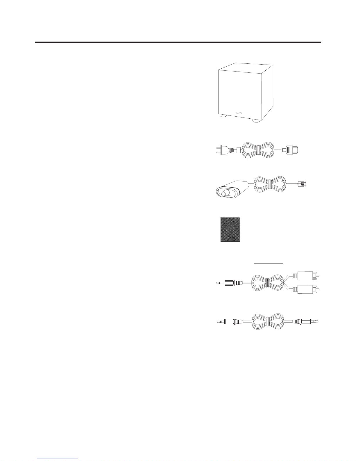
CARTON CONTENTS
A) One Subwoofer/Amplifier Loudspeaker
B) AC Cord
C) Volume Control
D) Hook and Loop fastener (for volume control, if desired)
Both signal cables (listed below) are 2-meters long.
E) Stereo Signal Cable, Red and White RCA Plugs
to Green Miniplug
Plugs into LINE IN A or LINE IN B
Connect to any analog sound source with dual RCA
stereo output jacks.
F) Stereo Signal Cable, Green Miniplug
to Green Miniplug
Plugs into LINE IN A or LINE IN B
Connect to any analog sound source with a stereo
output jack, like Cambridge SoundWorks MusicWorks
™
,
a portable CD player, or a computer sound card.
A
B
E
C
F
To Signal Source
Signal Cables
To BassCube
D
Page 6

666
CONNECTION DIAGRAM
+
BASS
TREBLE
PO
+
Green plug – to a stereo minijack analog out
(MusicWorks, sound card, portable CD play
LINE OUT
RIGHT
LEFT
OUTPUTS
Dual RCA to Minijack – to typical home audio source
or TV ouput
Home Audio source,
DVD Player, etc.
I
F
Analog Signal Cable
E
Page 7

7
POWER
120VAC 60Hz
RISK OF FIRE
REPLACE FUSE
AS MARKED
SPEAKERS
LINE IN
A
B
VOLUME CONTROL
L
R
+
+
Page 8

888
POSITIONING YOUR SPEAKERS
SUBWOOFER/AMPLIFIER
Place the Subwoofer cabinet on the floor, preferably
near a wall. Do not place it on a desktop or shelf.
For maximum bass output, place the subwoofer
near a corner. If the subwoofer is placed away from
the intersection of two room surfaces, the maximum
bass output will be reduced.
Use the Bass Level control to adjust the bass output to
your desired balance. Recommended Bass control
settings for each type of location are shown.
Because all satellite speakers will have different sensitivity, final adjustment should be done by ear even if
the settings do not agree with those shown here.
SATELLITES
Refer to the instructions that came with your
satellite speakers.
+
BASS
+
BASS
+
BASS
Maximum Bass Output Moderate Bass Output Least Bass Output
Suggested
Bass Control
Compensation
Page 9

+
BASS
TREBLE
POWER/STANDBY
SPEAKERS
LINE IN
A
B
VOLUME CONTROL
L
R
+
+
+
CONNECTIONS
Volume Control
It is not necessary to connect the Volume Control if your
audio signal source provides an output level adjustment.
The volume control allows use with a source that do not
have volume control, or where the source’s volume control is inconvenient.
A) If you are using the ST50 Desktop Stand with
Newton Series MC50 or MC100 speakers, slide the
Volume Control onto the support strut on one
of the stands.
If you are not using the ST50 Desktop Stands, we
have included a piece of hook and loop fastner
material so that you may attach the control to any
convenient surface.
B) Insert the Volume Control’s plug into the jack
marked VOLUME CONTROL on the Subwoofer
input panel until it snaps in place.
Signal Connections
The BassCube 821 has two analog inputs.
C) LINE IN A: Connect the 3.5 mm minijack output of
any analog signal source to this 3.5 mm stereo
minijack input.
LINE IN B is a second audio input that blends
with LINE IN A. Connect a second audio source
program here. For a source with a 3.5 mm minijack
output (like a headphone jack or line out jack on a
portable CD player), use a 2-meter signal cable
with a 3.5 mm miniplug at each end. Other sources
may need a cable with a 3.5 mm miniplug and two
RCA plugs or a 3.5 mm stereo miniplug and
3.5 mm stereo minijack.
A
B
C
Line Inputs
Newton Series ST50 Desktop Stand –
recommended for MC50
and MC100 satellites
(optional)
9999
Page 10

Other Connection Situations
1) Using the BassCube 821system as a high perform-
ance stereo television sound system.
a) A stereo television with audio signal output typically
has two RCA-type jacks (one red, one white). To
connect to these jacks, use the cable with two RCA
plugs at one end and a 3.5 mm stereo miniplug at
the other end (included). Connect the miniplug to
LINE IN A of the BassCube 821 and the RCA plugs
to your television’s red and white RCA jacks. (Do
not connect to yellow RCA jacks. These are for
video signals.)
b) Some stereo televisions offer a choice of fixed or
variable audio output level. Choose the variable output. The fixed output level bypasses the television’s
remote volume control.
c) Turn off your television’s internal speakers. This
control could be located on the front or back
control panels of your television, or it may be an
“on-screen” menu selection.
VIDEO IN
1
2 3
AUDIO
OUT
(VARIABLE)
VIDEO
AUDIO
L
(MONO)
R
d) If your television has a variable audio output, you
may not need to connect the BassCube 821’s
volume control. The television’s remote control will
adjust the volume level.
You will need to connect the BassCube 821
volume control if either of these situations occurs:
* Noise is heard even at the television’s minimum
volume setting. In this case, connect the volume
control and set it low enough to make the noise
inaudible, then stow the volume control next to the
subwoofer.
* You find the BassCube 821 is too “sensitive.” For
instance, if the output level is too loud when the
television “volume” setting is below 30%. Connect
the volume control and reduce it’s setting to
increase your television’s volume range. Then stow
the volume control next to the subwoofer.
Signal Cable
One 3.5 mm stereo miniplug to two RCA plugs
To BassCube 821
LINE IN A or LINE IN B
10101010
Page 11

11
2) Using the BassCube 821 system as a sound system
for a component CD player.
Typically, there are two RCA-type jacks (one red,
one white) on the CD player. To connect to these
jacks, use the stereo signal cable with two RCA
plugs on one end and a 3.5 mm stereo miniplug at
the other end. Connect the miniplug to LINE IN A of
the BassCube 821 and the RCA plugs to your
CD player’s red and white RCA jacks.
RIGHT
LEFT
OUTPUTS
Signal Cable
One 3.5 mm stereo miniplug to two RCA plugs
COMPONENT CD OUTPUT
Page 12

12
Speaker Connections
To connect the speaker cables.
The BassCube 821 will accept your choice of speaker
wire up to AWG#16. We recommend at least AWG#18
for runs up to 12 feet, and AWG#16 for longer runs.
Speaker wire is generally marked in some way to help
identify the “+” and “–” conductors at each end.
Sometimes this is done by printing on the jacket, a ribbon stripe molded in, or different color wires. Be certain to maintain the proper polarity at each connection.
Push back the red speaker output tab on the rear
panel “R” speaker output exposing the wire hole.
Fully insert one of the wires into the wire hole and
release the tab.
Repeat the procedure with the adjacent speaker wire
and the black speaker output tab for the Right channel.
Connect the two wires at the other end of that same
speaker cable to the “+” and “–” connections on the
right-hand satellite speaker. This satellite becomes the
Right channel satellite. Use the same wire for “+” at
both ends.
Repeat the preceding process to connect the other
satellite (making it the Left channel satellite).
POWER
120VAC 60Hz
RISK OF FIRE
REPLACE FUSE
AS MARKED
AC Connection and Placement
Make sure the subwoofer Power switch is in the OFF
position (O).
Plug the supplied power cable first into the subwoofer
back panel AC socket. Then connect it to an AC
power socket.
Place the satellites and subwoofer in their preferred
positions, then switch the Power swith to the ON (I)
position.
Page 13

OPERATION AND FINAL ADJUSTMENT
1) Use the Volume Control or the signal source control
to vary output level.
2) Defeat or cancel any “tone control” or other sound
adjustments within your audio program source.
Portable CD players may have “bass boost” switches and many computer sound programs have
audio adjustments concealed in drop-down menus.
3) If possible, play a variety of musical CDs with good
deep bass content to judge the best setting of the
Bass and Treble controls.
Auto Standby Mode
When audio signal is absent for 30 seconds or more,
the BassCube 821 amplifier is muted and goes into
Standby Mode. When the signal returns, the amplifier
will unmute. It is normal for the BassCube 821 to
remain slightly warm when in Standby Mode. It may
be left in Standby Mode indefinitely.
Cleaning
The painted surfaces of the satellites and subwoofers
should be wiped with a cloth or brushed clean.
TREBLE
+
+
BASS
13131313
Page 14

IMPORTANT: Turn off and unplug the
speaker before changing the fuse.
Use only with a 250V fuse
Employer uniquement avec
un fusible de 250V
SPECIFICATIONS FUSE REPLACEMENT
Analog Input:
775 millivolts for full output
10 kohms input impedance
Amplifiers:
Satellite: 60 watts continuous at 1 kHz, two channels
driven at less than .1% total harmonic distortion.
Subwoofer: 150 watts continuous at 100 Hz, one channel driven at less than .3% total harmonic distortion.
System Frequency response:
Satellite: 150 Hz to 20 kHz, +/- 3 dB
Subwoofer: 32 Hz to 150 Hz +/- 3 dB
Drivers:
Nominal 8 inch subwoofer driver
AC Voltage:
120VAC, 60Hz
Dimensions (H x W x D) and Weights
Subwoofer
11 1/8" x 10" x 10"
263mm x 255mm x 255mm
14 pounds, 8 ounces
6.6 kg
Fuse Replacement
The fuse holder is located in the power connector
at the base of each speaker. The fuse is a 2.5A
MDL type.
To replace the fuse:
1. Unplug the AC cord from the AC power source,
then remove the AC power cord from the speaker’s
power connector.
2. Remove the fuse cap with a small, flat blade screw-
driver (see diagram 2).
3. Remove the fuse from the fuse cap
(see diagram 3).
4. Replace the fuse inside fuse cap with another met-
ric 5X20mm size fuse (see diagram 4).
5. Replace the fuse and cap in the power connector
(see diagram 5).
6. Connect the AC power cord to the speaker.
7. Connect the power cord to an AC power outlet.
2.
3.
5.4.
14141414
Page 15

15
Page 16

P81-1910
CAMBRIDGE SOUNDWORKS, INC.
26 Dartmouth Street, Westwood, MA 02090
Telephone: 1-800-367-4434
Fax: 1-617-527-3194
A Company
 Loading...