

Page 1
1
340A SE
Issue Date: 9th August 2006
________________________________________________________________________
SERVICE MANUAL
________________________________________________________________________
SPECIFICATIONS:
Power Output 45W (into 8Ω)
55W (into 4Ω)
Max Power Consumption 360W
Total Harmonic Distortion 1kHz < 0.01%
20kHz < 0.01%
Frequency Response (-1dB) 5Hz – 50kHz
S to N Ration (unweighted) 92dB
Slew Rate (into 8Ω) 20V/uS
Dimensions (HxWxD)
mm 70 x 430 x 310
Inches 2.8 x 16.9 x 12.2
Weight
Kg 6.2
Lbs 13.6
AP20599/1
Gallery Court Hankey Place London SE1 4BB UK
Tel: +44 (0)20 7940 2200 Fax: +44 (0)20 794 0 2233
Page 2

2
340A SE SERVICE MANUAL
TABLE OF CONTENTS
Safety Precautions & Important Notes
Exploded Drawing
Exploded Drawing Parts List
Amplifier PCB Schematic (Tone Control)
Amplifier PCB Schematic (Power Supplies)
Amplifier PCB Schematic (Power Amplifier)
Amplifier PCB Schematic (Ipod Input Circuit)
Amplifier PCB Schematic (Input Select)
Amplifier PCB Board Layout (Top Side)
Amplifier PCB Board Layout (Bottom Side)
PCB Main Assembly BOM
Microcontroller PCB Schematic
Microcontroller PCB Board Layout (Top Side)
Microcontroller PCB Board Layout (Bottom Side)
Front Panel PCB Assembly BOM
IC Pin Layout Details
3
4
5
6
7
8
9
10
11
12
13-14
15
16
17
18
19-20
Page 3
SAFETY PRECAUTIONS & IMPORTANT NOTES
3
1. Check that the rear of the product indicates the correct supply voltage for
your area.
2. The lighting flash with the arrowhead within an equilateral
triangle is intended to alert the user or service agent to the
presence of dangerous voltages within the product enclosure that
may be of sufficient magnitude to constitute a risk of electric shock
to persons.
3. The exclamation point within an equilateral triangle is intended
to alert the user or service agent to the presence of important
operating and maintenance (Servicing) instructions in the literature
accompanying the appliance.
4. This product complies with EEC Low Voltage (73/23/EEC) and
Electromagnetic Compatibility (89/336/EEC) Directives when used and serviced
in accordance with this manual. For continued compliance all components
marked safety and EMC critical must only be replaced by Cambridge Audio
approved parts.
5. Any unauthorised design alterations or additions will void the manufacturer’s
warranty; furthermore the manufacturer cannot accept responsibility for personal
injury or property damage resulting therefrom.
6. When servicing, care should be taken to observe the original routing and
dressing of the leads and it should be confirmed that they have been returned to
normal after re-assembly.
Notes on chip component replacement
Never reuse a component that has been removed from a PCB
Notice that the minus side of a tantalum capacitor may be damaged by heat
COPYRIGHT NOTICE.
© 2006 Audio Partnership PLC. All rights reserved.
Cambridge Audio and Azur are registered trademarks for Audio Partnership PLC. This document
may not be reproduced, distributed, transmitted, displayed, published, or broadcast without the
express written prior permission of Audio Partnership PLC.
Alteration or removal of any trademark, copyright, or other notice from this content is prohibited.
Information provided in this document is provided solely for the use of official service agents in
repairing and servicing Audio Partnership PLC products.
Page 4
Cambridge Audio Azur 340A SE Amplifier
To enhance viewing, please print A3 4
6
9
8
7
1
8
7
6
11
11
12
11
2
10
3
10
4
5
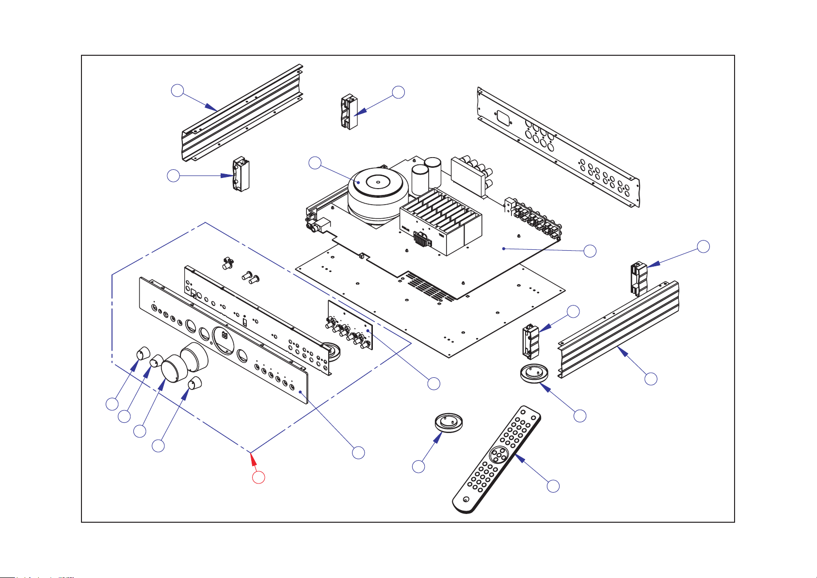
Exploded Drawing
Page 5
Cambridge Audio Azur 340A SE Amplifier
5
Drawing
Reference
1 PY1192 9434-015010E11 Azur 340A SE Main PCB 230V AP199543 Rev A Type
2 PY1193 9434-015010E41 Azur 340A SE Control PCBA AP151856 Rev A
3 PY1197 6534-150007E000A01 Azur 340A SE Front Panel - Silver with Silkscreen (Metal-work Only)
3 PY1196 6534-150007E000-01 Azur 340A SE Front Panel - Black with Silk screen (Metal-work Only)
4 PY1194 8534-015030E301 Azur 340A SE Front Panel Assy (Silver) Rev A
4 PY1195 8534-015040E301 Azur 340A SE Front Panel Assy (Black) Rev A
5 PY1012 Remote Control (340/540/640A)
6 PY810 6550-010207-000-02 Azur-640C Small Side Panel (Silver)
6 PY1115 6550-010207-000-01 Azur 640C Small Side Panel (Black)
7 PY1111 8554-001020-701 Small Support Rear Assy (with two brass inserts)
8 PY1112 8554-001010-701 Small Support Front Assy (with two brass inserts)
9 PY642 3200-069331E000 Transformer (T06933A rev 06) 230V 24V*2/3A 17*2/150ma 340A (Europe version)
9 PY1084 3200-071211-000 TR. (T0712A REV03) 115VAC 24.7V*2@3A 17V*2@0.15A 340A (USA version)
10 PY541 6050-150010-000A01 Foot (Silver)
10 PY531 6050-150010-000 Foot (Black)
11 PY592 6050-150004-002-02 Azur-640A Grey Colour Selector Knob (Silver)
11 PY593 540A/640A Selector Knob (Black)
12 PY590 540A/640A Volume Knob (Silver)
12 PY591 540A/640A Volume Knob (Black)
AP Part
Number
PY640 Top Panel (Silver)
PY641 Top Panel (Black)
PY516 7002-608010-006 Lid T6 Torx Screws (Silver)
PY515 7002-608010-001 Lid T6 Torx Screws (Black)
PY945 6040-150002-000-01 Battery Door for Azur R/C Black Painted (USD)
PY544 6600-170100-000 Foot Pad (Self Adhesive)
Factory Part No Description
*Please order using AP part number.
Exploded Drawing Parts List
Page 6
Cambridge Audio Azur 340A SE Amplifier
To enhance viewing, please print A3 6
R SEL OUT
L SEL OUT
TREBLE
R3
4k7
R11
8k2
BASS
TREBLE
R43
4k7
R45
8k2
VR3:B
B20K LINEAR
BASS
VR2:A
B20K LINEAR
VR3:A
B20K LINEAR
VR2:B
B20K LINEAR
C11
150n poly
C6
150n poly
5
C10
330p poly
R20
22k
5
2
C1
330p poly
C19
13
R2
4k7
C9
47U 16V EL
R52
150k
SW1:B
SW-DPDT
DEFEAT
VR1:A
R1
22k
2
13
R4
8k2
+15V
3
2
10p
C17
47n poly
84
U2:A
1
NE5532
C20
47U 16V EL
R59
150k
20K MOTORISED DUAL POT
2
1 3
C16
47n poly
-15V
TONE CONTROL VOLUME/BALANCE CONTROL
C29
46
R42
4k7
47U 16V EL
R54
150k
C15
R44
8k2
46
10p
U2:B
5
6
7
NE5532
C32
47U 16V EL
R60
150k
SW1:A
SW-DPDT
DEFEAT
VR1:B
5
4 6
20K MOTORISED DUAL POT
VR4:B
5
4 6
MN20K BALANCE
ZERO LOSS
WHEN CENTRAL
VR4:A
13
2
MN20K BALANCE
POWER AMP RIGHT
POWER AMP LEFT
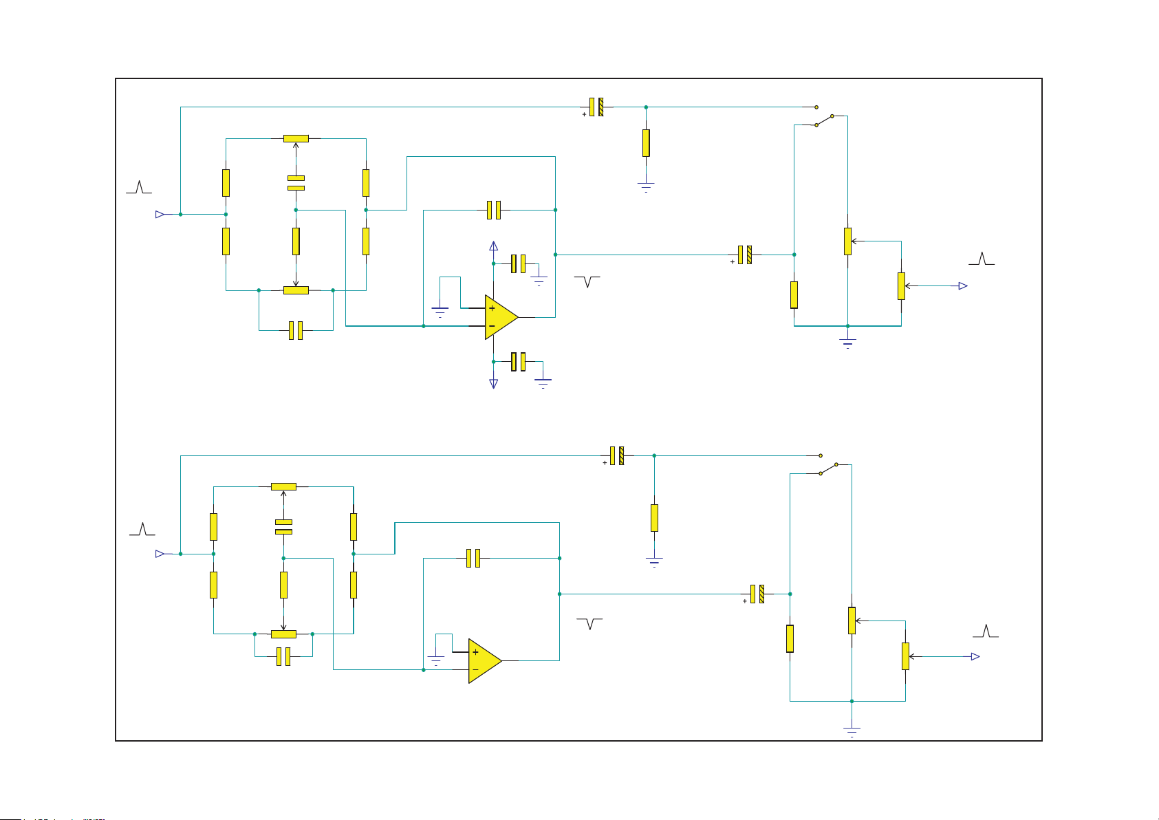
AP19951/3 Amplifier PCB Schematic (Tone Control)
Page 7

Cambridge Audio Azur 340A SE Amplifier
To enhance viewing, please print A3 7
MAINS GND
To sheet 1
CN3
IEC-SOC
MAINS SWITCH PCB
L
earth
E
N
C34
X1 10n
C35
X1 10n
F3
20MM T6.3AL or 3.15AL
C44
X2 470N SUPPRESSION
ALTERNATIVE POSITIONS FOR
X-CAPS WITH DIFFERENT LEAD PITCHES
C28
X2 470N SUPPRESSION
SW3
KDC-A04-10
J6
12
BROWN/BLACK
TO MAINS TRANSFORMER
J5
BLUE/WHITE
FROM TRANSFORMER
J7
TERMINAL
green
J10
TERMINAL
blue
J9
TERMINAL
purple
20MM T1AL
20MM T1AL
F4
F5
D5
1N4002D61N4002
D7
1N4002D81N4002
C45
1000u 35V
C46
470u 35V
+20V
FROM TRANSFORMER
J3
23V
TERMINAL
J4
0V
TERMINAL
J8
23V
TERMINAL
1
C51
47n poly
U8
7815
1
2
F1
T6A3 AL
LVD!
F2
T6A3 AL
LVD!
U5
7805
VI
OPAMP SUPPLY
VI
2
VI
U9
7915
MICROCONTROLLER SUPPLY
3
VO
GND
2
3
VO
GND
1
GND
3
VO
C48
47n poly
C52
47n poly
C53
47n poly
D1
1N5402
D2
1N5402
D3
1N5402
D4
1N5402
C47
47u 16V
C49
100u 25V
C50
100u 25V
+28V
C24
6800uF-50V
POWER AMP SUPPLY
C27
6800uF-50V
+5V
+15V
R49
1K8
P1
PAD
POWER LED
P2
PAD
-15V
-28V
AP19951/3 Amplifier PCB Schematic (Power Supplies)
Page 8

Cambridge Audio Azur 340A SE Amplifier
To enhance viewing, please print A3 8
POWER AMP LEFT
POWER AMP RIGHT
MUTE
HI = MUTE
R82
470R
R73
47K
R74
47K
R81
470R
+28V
POWER AMPLIFIER LEFT
R66
U6
11
NC26NC2NC3
R61
220R 3W C
R63
R56
RES2W 10R
C2
100nF 100V
R68
RES2W 10R
C36
100nF 100V
L1
R48
RES2W 2R2
40W 8 Ohms
= 17.9 Vrms
L2
R67
RES2W 2R2
5
4
12V 8A RELAY
RL1:B
8
7
12V 8A RELAY
RL1:C
5
CN2:C
LEFT: SPEAKER A
C67
MAINS GND
CN2:A
LEFT: SPEAKER B
C68
MAINS GND
SPKR 4-WAY
SPKR 4-WAY
3
6
1nF
1
2
1nF
SW2:B
SW-DPDT
SPEAKER B ON/OFF
SW2:A
SW-DPDT
CN2:B
SPKR 4-WAY
3
RIGHT
4
SPEAKER B
C69
1nF
MAINS GND
CN2:D
SPKR 4-WAY
6
7
SPEAKER A
8
RIGHT
C70
1nF
R77
47K
MAINS GND
C54
22U 50V NP
R78
47K
C55
22U 50V NP
3
OUT
MUTE
LM3886
8
C23
NC26NC2NC3
MUTE
8
Q2
BC337
-28V
11
OUT
LM3886
100U 16V NO FIT
U7
3
100U 16V NO FIT
C39
R9
27K
27K
220R 3W C
R64
470R 1W C
470R 1W C
OUTPUT RELAY
+15V
R80
3K3
1N4148
D11
1N4148
D10
1N4148
D13
1N4148
D14
D15
1N4148
Q5
BC337
Q4
BC327
R79
1K8
D12
1N4148
-15V
DC OFFSET DETECT
R62
1
5
V+2
LM3886
GND
4
7
27K
R57
-28V
270K
R53
C73
10pF
AMP MUTE
C3
10U 16V
R58
22K
C72
33pF
C40
C41
100U 50V HR
R8
1K
C22
47U 16V EL
V+
100U 50V HR
10
+
9
-
V-
+28V
POWER AMPLIFIER RIGHT
1
C42
100U 50V HR
100U 50V HR
R65
1K
C38
47U 16V EL
10
C43
V+
+
9
-
V-
C37
10U 16V
+5V
Q1
BC327
R71
47K
R72
47K
R70
22K
C71
33pF
5
V+2
LM3886
GND
4
7
27K
R69
270K
R55
-28V
C74
10pF
AMP MUTE
CN1
8
7
3
2
4
5
1
HEADPHONE JACK
R76
4K7
R12
3K9
R13
2K2
TIP = LEFT
RING = RIGHT
D9
1N4001
D16
5V1
RSW1
RSW2
R
L
LSW2
LSW1
GND
+20V
R75
220R
1/2 W
RL1:A
1
2
12V 8A RELAY
Q3
BC337
DC OFFSET
HI = NORMAL
360R
AP19951/3 Amplifier PCB Schematic (Power Amplifiers)
Page 9

Cambridge Audio Azur 340A SE Amplifier
To enhance viewing, please print A3 9
CN6
CKX-3
FOR 340A SE = FIT ALL COMPONENTS EXCEPT LK506 & LK507
FOR 340A = ONLY FIT LK506 & LK507
DO NOT FIT OTHER COMPONENTS
CN7
CN11
2,5MM 6W ST HEADER
100p
C82
1
2
3
4
5
6
5
4
2
3
6
7
1
100k
R96
100p
C77
GND_IPOD
100k
R97
LK308
LINK5MM
1
2
IPOD_L
3
GND
4
5
6
SHIELD
2,5MM 6W ST HEADER
IPOD_R
L CH IN
ipod input = 282mV
R CH IN
J2 Pin 9
LK210
LINK10MM
R86
1k
R90
1k
LK211
LINK10MM
LK212
LINK15MM
LK213
LINK10MM
C78
10U 16V
R87
100k
R88
3k9
INPUT BUFFER +24dB
C80
10U 16V
R91
100k
+5V
LK305
LINK10MM
R95
1k
3
2
5
6
C79
22p
84
R89
62k
+15V
-15V
R85
10k
U3:A
NE5532
C75
47n poly
C76
47n poly
U3:B
7
NE5532
+15V
R94
91R
RL2:A
D17
1N4001
1
2
RELAY
LK303
LINK10MM
Q6
BC337
FIT ONLY FOR 340A
LK506
4
5
LINK5MM
RL2:B
RELAY
L SEL OUT
3
LK304
LINK10MM
1
LK302
LINK10MM
FIT ONLY FOR 340A
LK507
LINK5MM
RL2:C
LK301
LINK10MM
7
8
RELAY
R SEL OUT
6
LK200
LINK10MM
R92
3k9
R93
62k
C81
22p
AP19951/3 Amplifier PCB Schematic (Ipod Input Circuit)
Page 10

Cambridge Audio Azur 340A SE Amplifier
To enhance viewing, please print A3 10
C26
LEFT RIGHT
CN9:B
DUAL PHONO
3
R50
220K
C66
CN8:B
QUAD PHONO
3
TAPE OUT L
TAPE RETURN LEFT
R84
220K
C65
R16
220K
CN5:B
C64
QUAD PHONO
QUAD PHONO
3
DVD
AV/MD
R6
R15
220K
220K
C63
CN8:D
6
CN4:B
QUAD PHONO
CN4:D
CN5:D
QUAD PHONO
3
6
TUNER/DAB
R5
220K
C61
C62
QUAD PHONO
MAINS GND
6
AUX L
CD
R21
220K
C60
100nF 100V
R47
100R
CN4:A
QUAD PHONO
CN4:C
QUAD PHONO
1
4
2
5
AUX R
CD
R22
R32
220K
220K
C56
C57
CN5:A
QUAD PHONO
CN5:C
QUAD PHONO
1
4
2
5
TUNER/DAB
R23
220K
C33
5
DVD
AV/MD
R30
220K
C31
CN8:C
4
R31
220K
C30
CN8:A
QUAD PHONO
QUAD PHONO
1
1
CN9:A
DUAL PHONO
2
2
TBT
B
LRLR
23 56
AB CD
TAPE OUT R
R83
220K
TAPE RETURN RIGHT
R51
220K
C21
C18
R46
10U 35V NP
1k
10U 35V NP
R181KR19
1k
10U 35V NP
10U 35V NP
R17
R14
1k
1k
10U 35V NP
10U 35V NP
R10
R7
1k
1k
-15V +15V
10U 35V NP
C4
47n polyC547n poly
1
2
3
4
5
6
7
8
9
10
11
12
13
14
U4
Vss
L-S1
L-S2
L-S3
L-COM1
L-S4
L-S5
L-S6
L-COM2
L-S7
L-S8
L-COM3
ST
GND
TC9163
R-COM1
R-COM2
R-COM3
Vdd
28
R-S1
27
R-S2
26
R-S3
25
24
R-S4
23
R-S5
22
R-S6
21
20
R-S7
19
R-S8
18
17
DATA
16
CLK
15
INPUT/TAPE SELECT SWITCH
J2 Pin 9
OUTPUT RELAY
DC OFFSET
MUTE
10U 35V NP
R241kR251kR261kR271kR28
+5V
J2
9
8
7
6
5
STROBE
4
CLOCK
3
DATA
2
1
2,5MM 9W 90 HEADER
MICROCONTROLLER
BOARD CONNECTOR
10U 35V NP
10U 35V NP
9 Way
J2 on AP19952/3
9 Way
J2 on AP19952/3
10U 35V NP
FOR 340A SE
FOR 340A
pin 9 not connected for 340A
10U 35V NP
10U 35V NP
10U 35V NP
R29
1k
R41
1k
1k
Pin 27 on U1
on AP14519/3
8 Way
CN2 on AP14519/3
8 Way
CN2 on AP14519/3
R40
100k
R39
100k
C58
10 pF
C25
10U 16V
R34
10k
C14
10U 16V
R37
R38
100k
100k
R36
10k
INPUT BUFFER +6dB
C59
10 pF
+15V
C7
84
47n poly
U1:A
3
1
2
NE5532
C8
47n poly
-15V
R CH IN
R33
10k
C12
22p
U1:B
5
7
6
NE5532
L CH IN
R35
10k
C13
22p
AP19951/3 Amplifier PCB Schematic (Input Select)
Page 11

Cambridge Audio Azur 340A SE Amplifier
To enhance viewing, please print A3 11
AP19951/3 Amplifier PCB Board Layout (Top Side)
Page 12

Cambridge Audio Azur 340A SE Amplifier
To enhance viewing, please print A3 12
AP19951/3 Amplifier PCB Board Layout (Bottom Side)
Page 13

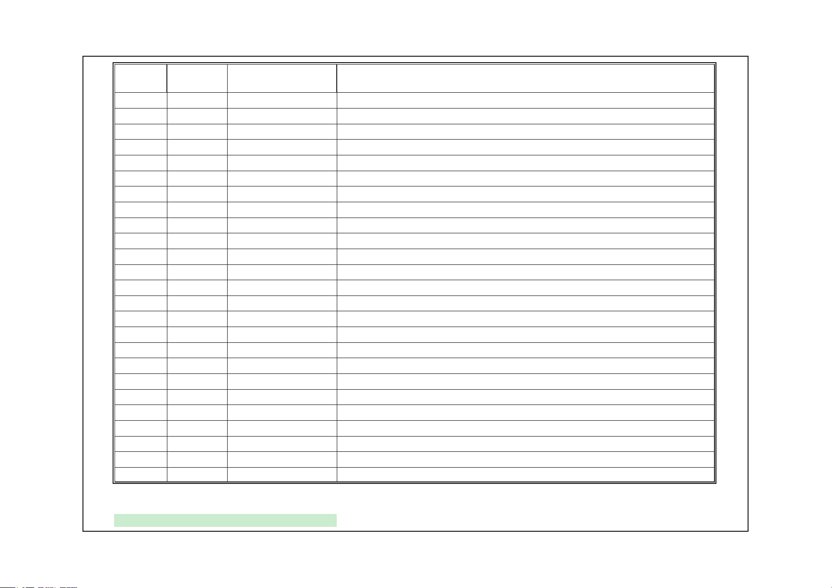
Cambridge Audio Azur 340A SE PCB Main Assembly BOM
13
AP Part No Value Description Qty Component Ident Notes
RESISTORS
2R2 2W Metal Film 2 R48, R67 Stand off PCB by 5mm
10R 2W Metal Film 2 R56, R68 Stand off PCB by 5mm
91R 2W Metal Film 1 R94
100R 0.25 W 1% Metal Film 1 R47
220R 0.5 W Metal Film 1 R75
220R 3W Metal Film 2 R61, R63 Stand off PCB by 5mm
470R 0.25 W 1% Metal Film 2 R81, R82
470R 1W Metal Film 2 R62, R64 Stand off PCB by 5mm
1K 0.25 W 1% Metal Film 18
1K8 0.25 W 1% Metal Film 2 R49, R79
2K2 0.25 W 1% Metal Film 1 R13
3K3 0.25 W 1% Metal Film 1 R80
3K9 0.25 W 1% Metal Film 3 R12,R88,R92
4k7 0.25 W 1% Metal Film 5 R2, R3, R42, R43, R76
8k2 0.25 W 1% Metal Film 4 R4, R11, R44, R45
10k 0.25 W 1% Metal Film 5 R33-R36,R85
1K 0.5 W Metal Film 1 R95
22k 0.25 W 1% Metal Film 4 R1, R20, R58, R70
27K 0.25 W 1% Metal Film 4 R9, R57, R66, R69
47K 0.25 W 1% Metal Film 6 R71-R74, R77, R78
62K 0.25 W 1% Metal Film 2 R89, R93
100K 0.25 W 1% Metal Film 8 R37-R40, R87,R91, R96, R97
150k 0.25 W 1% Metal Film 4 R52, R54, R59, R60
220K 0.25 W 1% Metal Film 14
270K 0.25 W 1% Metal Film 2 R53, R55
CAPACITORS
22pF Ceramic NPO. Pitch= 5.0mm 4 C12, C13,C79,C81
33pF Ceramic NPO. Pitch= 5.0mm 2 C71, C72 EMC Suppression
10pF Ceramic NPO. Pitch= 5.0mm 6 C9, C15, C58, C59, C73, C74
100pF Ceramic NPO. Pitch= 5.0mm 2 C77, C82
330pF Polyester. Pitch= 5.0mm 2 C1, C10
1nF Ceramic Y5P 50V. Pitch= 5.0mm 4 C67,C68,C69,C70 EMC Suppression
10nF X1 Mains rated Ceramic. Pitch= 5.0mm 2 C34, C35 EMC Suppression
47nF Polyester Pitch= 5.0mm 12
100nF Ceramic 100V Pitch= 5.0mm 3 C2, C26, C36
150nF Polyester Pitch= 5.0mm 2 C6, C11
470nF
10uF Electrolytic 35V NP Pitch= 2.0mm 20
22uF Electrolytic 50V NP Pitch= 2.0mm 2 C54, C55
47uF Electrolytic 16V Pitch= 2.5mm 5 C20, C22, C32, C38, C47
47uF Electrolytic 16V NP Pitch= 2.5mm 2 C19, C29 Silk print is electrolytic
100uF Electrolytic 50V HR Pitch= 5.0mm 4 C40-C43
100uF Electrolytic 25V Pitch= 2.5mm 2 C49, C50
470uF Electrolytic 35V Pitch= 5.0mm 1 C46
1000uF Electrolytic 35V Pitch= 5.0mm 1 C45
10000uF
SEMICONDUCTORS
PY259 NE5532 Dual Low Noise Operational Amplifier 3 U1,U2, U3 DIL package
PY476 TC9163AF Input Switching 1 U4 surface mount package
PD035 7805T Voltage Regulator +5V 1 U5 TO220 package
PY644 LM3886T High Performance Audio Power Amplifier 2 U6,U7
PD037 7815T Voltage Regulator +15V 1 U8 TO220 package
PD038 7915T Voltage Regulator -15V 1 U9 TO220 package
TRANSISTORS
PY219 BC327 PNP Small Signal 2 Q1, Q4
PY214 BC337 NPN Small Signal 4 Q2, Q3, Q5, Q6
X2 Mains rated Polypropylene. Pitch
22.5mm
Cambridge Audio Branded Electrolytic 50V
Pitch= 10.0mm
R7, R8, R10, R14, R17, R18, R19, R24-R28,
R29, R41, R46, R65,R86,R90,
R5, R6, R15, R16, R21-R23, R30-R32, R50,
R51, R83, R84
C4, C5, C7, C8, C16, C17, C48, C51-C53,
C75, C76
1 C28
C3, C14, C18, C21, C25, C30, C31, C33,
C37, C56, C57, C60, C61, C62, C63, C64,
C65, C66, C78, C80
2 C24, C27 Glue both capacitors to PCB
EMC. C44 is alternative fit for 27.5 mm
pitch
Some cap will have silk print of an
electrolytic
AP19954/3
NOte: resistors, capacitors amd other 'generic' electronic components are not usually stocked by the
manufacturer. Please obtain these locally.
Page 14

Cambridge Audio Azur 340A SE PCB Main Assembly BOM
14
AP Part No Value Description Qty Component Ident Notes
1N5402 General Purpose Rectifier 4 D1-D4
1N4002 General Purpose Rectifier 4 D5-D8
1N4001 General Purpose Rectifier 2 D9, D17
1N4148 High Speed Signal 6 D10-D15
BZX85-C5V1 Zener 400mW 1 D16
T6.3AL
T3.15AL OR T6.30AL
T1AL
PY594
PY004 20K MOTORISED DUAL POT Pot-Dual-Motor 1 VR1
PY003 B20K LINEAR Pot-Dual 2 VR2, VR3
PY005 MN20K BALANCE Pot-Dual 1 VR4
PY646 2330-005901-300 Headphone Jack 1 CN1 As 540A amplifier
PY647 WP8-21A Spkr 4-Way 1 CN2
PY226 YN 2336-003910-002 IEC-Socket 1 CN3 As 540A amplifier
PY036 YN 2330-006911-021 Quad Phono 3 CN4, CN5, CN8
PY035 AV2-8.4-9 Dual Phono 1 CN9
PY645 2402-020200-010 SW-DPDT 2 SW1, SW2 As 540A amplifier
PY227 KDC-A04-10 Mains switch 10A 250V TV-8 1 SW3 mains switch
12V coil, 8A 250VACMassuse
Me-11 012-2Z4
CKX-3.5-0.7 3.5mm HEADPHONE JACK 1 CN6
DIODES
MISCELLANEOUS
CONNECTORS
SWITCH
6.3A time delay Fuse-20mm low breaking
capacity
3.15A or 6.3A time delay Fuse-20mm low
breaking capacity
1A time delay Fuse-20mm low breaking
capacity
Relay-s 2 RL1, RL2
2 F1, F2 Secondary fuses
1F3
2 F4, F5 Secondary fuses
For EU & UK Models (230V) - F3 should
be fitted with T3.15AL.
For CU Models (115V) - F3 should be
fitted with T6.3AL.
AP19954/3
NOte: resistors, capacitors amd other 'generic' electronic components are not usually stocked by the
manufacturer. Please obtain these locally.
Page 15

Cambridge Audio Azur 340A SE Amplifier
To enhance viewing, please print A3 15
+5V +5V
6 mA
R4
AUX/PHONO CD TUNER/DAB
D1
CHANNEL LEDD2CHANNEL LEDD3CHANNEL LEDD4CHANNEL LEDD5CHANNEL LED
220R
DVD AV/MD
CRS1
DGND
R3
220R
TAPE MON
D6
CHANNEL LED
FREQ=4MHz
Vpp
Data I/O
CLK
+5V
GND
GND
SW1
AUX/PHONO
+5V
R1
CN1
ICP
100K
IN-CIRCUIT PROGRAMMING CONNECTOR
1
2
3
4
5
6
DGND
DGND
U1
1
MCLR/Vpp
2
RA0
3
RA1
4
RA2
5
RA3
6
RA4
7
RA5
8
Vss2
9
OSC1
10
OSC2
11
RC0
12
RC1
13
RC2
14
RC3
PIC16F72
PORT B HAS WEAK PULLUPS 250uA typ
OUTPUT RELAY
SW2
CD
TUNER/DAB
SW3
MUTE
+5V
C5
100n
DECOUPLE
SW4
DGND
HI = NORMAL
DC OFFSET
+5V
C7
100n
vol up
vol down
SW5
AV/MD
DGND
IR IN
SW6
TAPE MON
strobe
data
DVD
RB7
28
RB6
27
RB5
26
RB4
25
RB3
24
RB2
23
RB1
22
RB0
21
Vdd
20
Vss
19
RC7
18
RC6
17
RC5
16
RC4
15
DGND
OUTPUT RELAY
+5V
C4
100n
MUTE
strobe
clockclock
data
DECOUPLE
+5V
R2
47R
3
2
1
DGND
CN3
CN4
3
2
CN2
8
7
6
5
4
3
2
1
H8 2.54mm 90
1
CONN-H3
CONN-H3
CONN TO MAIN PCB
U2
C3
47u 16V
BA6218
VOLUME POT
MOTOR CONTROL
GND1
GND2
OUT2
OUT1
COM
FIN
RIN
NC
VCC
U3
OPT
1
GND
2
+5V
3
TSOP18 IR RECEI
IR RECEIVER
TSOP1835/37
+5V
1
2
3
4
5
6
7
8
9
DGND
C6
100n
vol up
vol down
C1
100n
10U 16V SM EL
DECOUPLE
CN5
2
1
H2 2.54mm 90
TO MOTOR
C2
AP14518/3 Microcontroller PCB Schematic
Page 16

Cambridge Audio Azur 340A SE Amplifier
To enhance viewing, please print A3 16
AP14518/3 Microcontroller PCB Board Layout (Top Side)
Page 17

Cambridge Audio Azur 340A SE Amplifier
To enhance viewing, please print A3 17
AP14518/3 Microcontroller PCB Board Layout (Bottom Side)
Page 18

Cambridge Audio Azur 340ASE Front Panel PCB Assembly BOM
18
AP Part
No
PY260 BA6218 Motor Controller 1 U2
PY054 TSOP1836/37 IR Receiver Module 1 U3 As used in 540A 3001-183600-001
PY064 3100-000030-003 Blue Flat top LED 6 D1-D6
PY043 2400-020200-000 Tactile Switch 6 SW1, 2, 3, 4, 5, 6
Value Description Qty Component Ident Notes
RESISTORS
47R Resistor 0.25W 1% metal film 1 R2
220R Resistor 0.25W 1% metal film 2 R3, R4
100K Resistor 0.25W 1% metal film 1 R1
CAPACITORS
100nF Ceramic NP0 or C0G 10% 4 C1, C4-C7
47uF 16V Radial Electrolytic 1 C3
SEMICONDUCTORS
PIC16F72-I/SP MicroController 1 U1
DIODES
SWITCH
MISC
Ceramic Resonator F=4MHz 1 CRS1
C1 is soldered on rear of the IR PCB
(solder side)
Programmed with AP14904/3 (V1.2)
Contact AP Service Dept
As used in 540A. 4162-180002-300
SIL-8 package
Please use flat top LED at standard Azur
height
As used on 540A, CD, Tuner, AV,
Phono/Aux, Tape/Mon, DVD
AP15185/7
Note: resistors, capacitors and other 'generic' electronic components are not usually stocked by the
manufacturer. Please obtain these locally.
Page 19

Cambridge Audio Azur 340ASE Amplifier IC Pin
19
Layout Details
Front Panel PCB
PIC16F72-I/SP (U1)
BA6218 (U2)
TSOP1836/37 (U3)
Page 20

Main PCB
20
NE5532 (U1 & U2)
TC9163AF (U4)
LM3886T (U6 & U7)
 Loading...