

Cambium Networks 89FT0045 User Manual

LTE RRH B40/B41 Quick Guide
Cambium Networks
V1
W
uhan Gewei Ele ctronic Technologies Co. Ltd.
2GHz Palisade 220
.0
Wuhan Gewei Electronic Technologies Co. Ltd. Page 1

Content
1 STRUCTURE &INTERFACE DESCRIPTION .......................................................................... 1
1.1 STRUCTURE &FRONT INTERFACE ............................................................................................. 1
1.1.1 Front Interface Description ............................................................................................. 2
1.1.2 Power Interface ............................................................................................................... 2
1.2 SIDE INTERFACE ........................................................................................................................ 3
1.2.1 Side Interface Description ............................................................................................... 3
1.2.2 Service Access and Operation Maintenanc e Window...................................................... 4
2 HARDWARE TESTING CONNECTION .................................................................................... 5
2.1 HARDWARE REQUIRED EQUIPMENT .......................................................................................... 5
2.2 SOFTWARE PREPARATION .......................................................................................................... 5
2.3 SERIAL AND ETHERNET CONFIGURATION ................................................................................. 6
2.4 CONNECTION FIGURE ................................................................................................................ 7
3 HARDWARE TEST LIST .............................................................................................................. 8
Wuhan Gewei Electronic Technologies Co. Ltd. Page 2
1 Structure &Interface Description
1.1 Structure &Front Interface
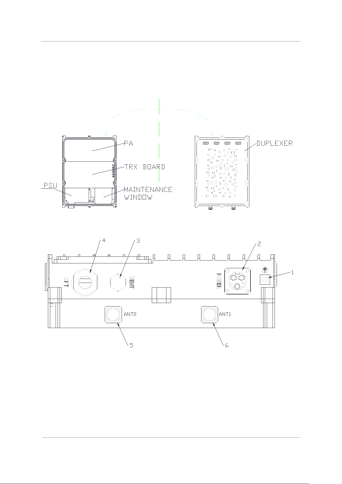
The LTE RRH B40/B41 structure &interface is shown as Figure 1-1:
Figure 1-1 structure of LTE RRH B40/B41
Figure 1-2 LTE RRH B40/B41 front interface
Wuhan Gewei Electronic Technologies Co. Ltd. Page 1

-48V DC Power supply Interface.
Please refer to 1.1.2 for Pin definition
N connector.
This will be modified in next version
Pin #
Name
Signal description (DC)
1.1.1 Front Interface Description
Table 1-1 LTE RRH B40/B41 Front Interface Description
# External interface description Remarks
1 Chassis ground
2 POWER
3 VENT Air vent
4 OPT Optical interface
5 ANT0
6 ANT1 N connector.
Actually Antenna port 2(ANT2)
1.1.2 Power Interface
The power supply interface requires a three-pin straight plug, and it provides a waterproof cover, DC
special connector, as shown in Figure 1-3; see Table 1-2 for detailed definition.
A Positive -48V RTN
B GND Ground
Wuhan Gewei Electronic Technologies Co. Ltd. Page 2
Figure 1-3 Power Interface Diagram
Table 1-2 PWR Interface Description
 Loading...