

Cambium Networks 58XX, 58XX-T Users manual

Orthogon Systems
There’s non-line-of-sight...
and then there’s
There’s line-of-sight...
User Manual

2

Orthogon Systems
Gemini System User Manual
May 16, 2003
Ref: PHN-0532-0006
Copyright Information
This document is the confidential property of PipingHot Networks Limited and without its prior written consent may not be copied or released to 3rd parties. © 2003 PipingHot Networks
Limited.
Compliance
Changes or modifications not expressly approved by Orthogon Systems could void the user’s
authority to operate the equipment.
Disclaimer
The parameters quoted in this document must be specifically confirmed in writing before they
become applicable to any particular order or contract. The company reserves the right to make
alterations oramendments to the detail specification at its discretion. The publication of information in this document does not imply freedom from patent or other rights of Orthogon Systems
or others.
1

Contents
1 Getting Started . . . . . . . . . . . . . . . . . . 4
1.1 For Your Safety . . . . . . . . . . . . . . . . 4
1.2 Welcome . . . . . . . . . . . . . . . . . . . . . 4
1.2.1 About This Guide . . . . . . . . . . . . . 4
1.2.2 Who Should Use This Guide . . . . 5
1.2.3 Service . . . . . . . . . . . . . . . . . . . . . 5
1.3 Product Description (About
the OS-Gemini) . . . . . . . . . . . . . . . . 5
1.3.1 The Outdoor Unit (ODU) . . . . . . . 6
1.3.2 The Indoor Unit (IDU) . . . . . . . . . 6
1.3.3 Mains Power Adaptor . . . . . . . . . 7
1.3.4 Cables and Connectors . . . . . . . . . 8
1.3.5 Surge Arrestor . . . . . . . . . . . . . . . 9
1.3.6 Mounting Brackets . . . . . . . . . . . 10
1.3.7 Configuration and Management . 11
1.4 Warranty . . . . . . . . . . . . . . . . . . . . 11
2 Product Architecture (More
Detail About The OS-Gemini) . . . . 12
3 General Considerations . . . . . . . . . . 14
3.1 Frequency Planning . . . . . . . . . . . 14
3.2 Distance . . . . . . . . . . . . . . . . . . . . . 14
3.3 Networking Information . . . . . . . . 14
3.4 Lightning Protection . . . . . . . . . . . 14
3.5 Electrical Requirements . . . . . . . . 15
3.6 Training . . . . . . . . . . . . . . . . . . . . . 15
4 Site Planning . . . . . . . . . . . . . . . . . . 16
4.1 Site Selection Criteria . . . . . . . . . . 16
4.1.1 ODU Site Selection . . . . . . . . . . . 16
4.1.2 IDU Site Selection . . . . . . . . . . . . 16
4.2 Path Loss Considerations . . . . . . . 16
4.2.1 Free Space Path Loss . . . . . . . . . 17
4.2.2 Excess Path Loss . . . . . . . . . . . . 17
4.2.3 Fade Margin . . . . . . . . . . . . . . . . 18
4.2.4 Maximum Path Loss . . . . . . . . . 18
4.2.5 Worked Example 1 . . . . . . . . . . . 19
4.2.6 Worked Example 2 . . . . . . . . . . . 19
4.3 Mean Power . . . . . . . . . . . . . . . . . 20
5 Installation . . . . . . . . . . . . . . . . . . . . 22
5.1 Preparation . . . . . . . . . . . . . . . . . . 22
5.2 Installation Procedure . . . . . . . . . . 22
5.3 Tools Required . . . . . . . . . . . . . . . 22
5.4 Installation Support . . . . . . . . . . . . 22
5.5 Legal Disclaimer . . . . . . . . . . . . . . 23
5.5.1 Mounting the ODUs . . . . . . . . . . 23
5.5.2 Connecting Up . . . . . . . . . . . . . . 25
5.5.3 Mounting The IDU . . . . . . . . . . . 30
5.5.4 Powering Up . . . . . . . . . . . . . . . . 31
5.5.5 Aligning the ODUs . . . . . . . . . . . 31
6 Web Page Reference . . . . . . . . . . . . 33
6.1 Home Page . . . . . . . . . . . . . . . . . . 33
6.2 Systems Status Page . . . . . . . . . . . 34
6.3 System Administration Page . . . . . 35
6.3.1 System Configuration Page . . . . 35
6.3.2 Install Pages . . . . . . . . . . . . . . . . 36
6.3.3 Software Upgrade Pages . . . . . . 38
6.3.4 DFS Pages . . . . . . . . . . . . . . . . . 39
6.3.5 SMTP Configuration Page . . . . . 40
6.3.6 Change System
Administration Password . . . . . . 41
6.3.7 Software License Key . . . . . . . . 41
7 Fault Finding . . . . . . . . . . . . . . . . . . 42
8 Specifications . . . . . . . . . . . . . . . . . . 43
8.1 System Specification . . . . . . . . . . . 43
8.2 Safety Compliance . . . . . . . . . . . . 44
8.3 EMC Emissions Compliance . . . . 44
8.4 EMC Immunity Compliance . . . . . 45
8.5 Radio Certifications (type
approvals) . . . . . . . . . . . . . . . . . . . 45
8.6 Environmental Specifications . . . . 45
8.7 System Connections . . . . . . . . . . . 46
8.7.1 ODU to IDU Connection . . . . . . 46
8.7.2 Network Connection . . . . . . . . . 46
8.7.3 Power Connection . . . . . . . . . . . 46
9 Lightning Protection . . . . . . . . . . . . 48
10 FAQs . . . . . . . . . . . . . . . . . . . . . . . . 50
11 Glossary . . . . . . . . . . . . . . . . . . . . . . 51
12 Index . . . . . . . . . . . . . . . . . . . . . . . . 52
2

List of Figures
1 Typical OS-Gemini Deployment . . . . 5
2 OS-Gemini Outdoor Unit (ODU) . . . . 7
3 OS-Gemini Indoor Unit (IDU) . . . . . . 8
4 OS-Gemini Reset Switch . . . . . . . . . . 9
5 OS-Gemini power adaptor . . . . . . . . 10
6 ODU Mounting Configurations . . . . . 10
7 OS-Gemini Layer Diagram . . . . . . . 12
8 Free Space Path Loss at 5.8GHz . . . 17
9 Fade Margin vs Excess Path
Loss for 99.99% link availability . . 18
10 Worked Example . . . . . . . . . . . . . . . 19
11 Worked Example over a hill . . . . . . 20
12 Mean path loss vs range for
BPSK and 16QAM . . . . . . . . . . . . . . . 20
13 RJ45 Pin Connections . . . . . . . . . . . 27
14 Web page menus . . . . . . . . . . . . . . . 33
15 Home Page . . . . . . . . . . . . . . . . . . . . 33
16 Status Page . . . . . . . . . . . . . . . . . . . . 34
17 System Administration Page . . . . . . 35
18 Configuration Page . . . . . . . . . . . . . 35
19 Licence key entry . . . . . . . . . . . . . . . 36
20 Installation page 1 — Internet
Protocol Settings . . . . . . . . . . . . . . . 36
21 Installation page 2 —
Wireless Configuration . . . . . . . . . . 37
22 Installation page 3 —
Confirm Installation . . . . . . . . . . . . 37
23 Installation page 4 —
Configuration Complete . . . . . . . . . 38
24 Software upgrade . . . . . . . . . . . . . . . 38
25 DFS page . . . . . . . . . . . . . . . . . . . . . 40
26 SMTP page . . . . . . . . . . . . . . . . . . . 40
27 Password page . . . . . . . . . . . . . . . . . 41
28 License page . . . . . . . . . . . . . . . . . . 41
29 Fault Finding Guide . . . . . . . . . . . . . 42
30 DC Connection Diagram . . . . . . . . . 46
31 ODU Mounting Positions . . . . . . . . 49
3

1 Getting Started
1.1 For Your Safety
Caution Users and installers should note that the mains power supply is the primary disconnect
device.
Warning Use extreme care when installing antennas near power lines.
Warning Use extreme care when working at heights.
Caution When the system is operational, avoid standing directly in front of the antenna. Strong
RF fields are present when the transmitter is on.The ODU must not be deployed in a location
where it is possible for people to stand or walk inadvertently in front of the antenna.
The Gemini 5810 Outdoor unit must be properly grounded to protect against power surges. It is
the user’s responsibility to install the equipment in accordance with Section 810 of the National
Electric Code, ANSI/NFPA No.70-1984 or Section 54 of the Canadian Electrical Code. These
codes describe correct installation procedures for grounding the outdoor unit, mast, lead-in wire
and discharge unit, size of grounding conductors and connection requirements for grounding
electrodes. It is recommended that installation of the outdoor unit be contracted to a professional
installer.
Caution Safety will be compromised if external quality cables are not used for connections
which will be exposed to the weather.
Caution Safety may be compromised if a different power supply is used than the one supplied
as part of the system.
Caution Safety may be compromised if the screws holding the bracket to the rear of the unit
are removed and reassembled more than once.
1.2 Welcome
Congratulations on the purchase of the OS-Gemini systems from Orthogon Systems. The OSGemini is the latest innovation in high-speed wireless networking that lets you deploy wireless
networks in areas previously unattainable.
1.2.1 About This Guide
This guide covers the installation, commissioning, operation and fault finding of the OS-Gemini
system.
4

1.2.2 Who Should Use This Guide
Building 1 Building 2
Enterprise LAN Enterprise LAN
Power
Adapter
Mains
Supply
Wall
Plate
CAT 5
Patch
CAT 5
Cable
The guide is for use by the system installer and the end user IT professional.
The system installer will require expertise in the following areas:
• Outdoor radio equipment installation
• Network configuration
• Use of web browser for system configuration, monitoring and fault finding
1.2.3 Service
For unit repair or service, contact your service provider or an authorised Orthogon Systems
distributor for authorisation and shipping instructions.
1.3 Product Description (About the OS-Gemini)
The OS-Gemini has primarily been developed to provide Point-to-Point data connectivity via a
5GHz wireless Ethernet bridge operating at broadband data rates. The OS-Gemini is aimed at
enterprises that have a requirement to connect together the Local Area Network (LAN) of two or
more buildings. Figure 1 illustrates such a deployment. It should be noted that the use of two
links requires a router at each end to provide load balancing and redundancy control which are
not shown.
Figure 1 Typical OS-Gemini Deployment
The OS-Gemini offers true non--Line--of--Sight (NLOS) operation by using a combination of Orthogonal Frequency Division Multiplex (OFDM) modulation and MultiBeam Space TimeCoding
(STC) techniques. Thesetechnologies enables theOS-Gemini to drivethroughfoliage and around
buildings to such an extent that almost universal coverage can be expected at short range.
5

The OS-Gemini consists of a pair of identical devices that are deployed one at each end of the
link. At install time the user sets up one unit is set as the Master and the other as the Slave. Either
unit can be configured as master or slave.
Each end of the link consists of:
• An integrated outdoor transceiver unit containing all the radio and networking electronics.
Hereafter referred to as the Outdoor Unit (ODU).
• An indoor passive connection box containing status indicators, DC power connection and
network connection. Hereafter referred to as the Indoor Unit (IDU).
• A ‘mains’ power adaptor.
Power is fed into the IDU from the mains power adaptor via a standard low voltage DC connector.
The network connection is presented to the user at the IDU via an RJ45 socket. Connection
between the ODU and IDU is made using standard CAT 5 UV resistant cable. The spare twisted
pairs of the cable are used to feed power from the IDU to the ODU.
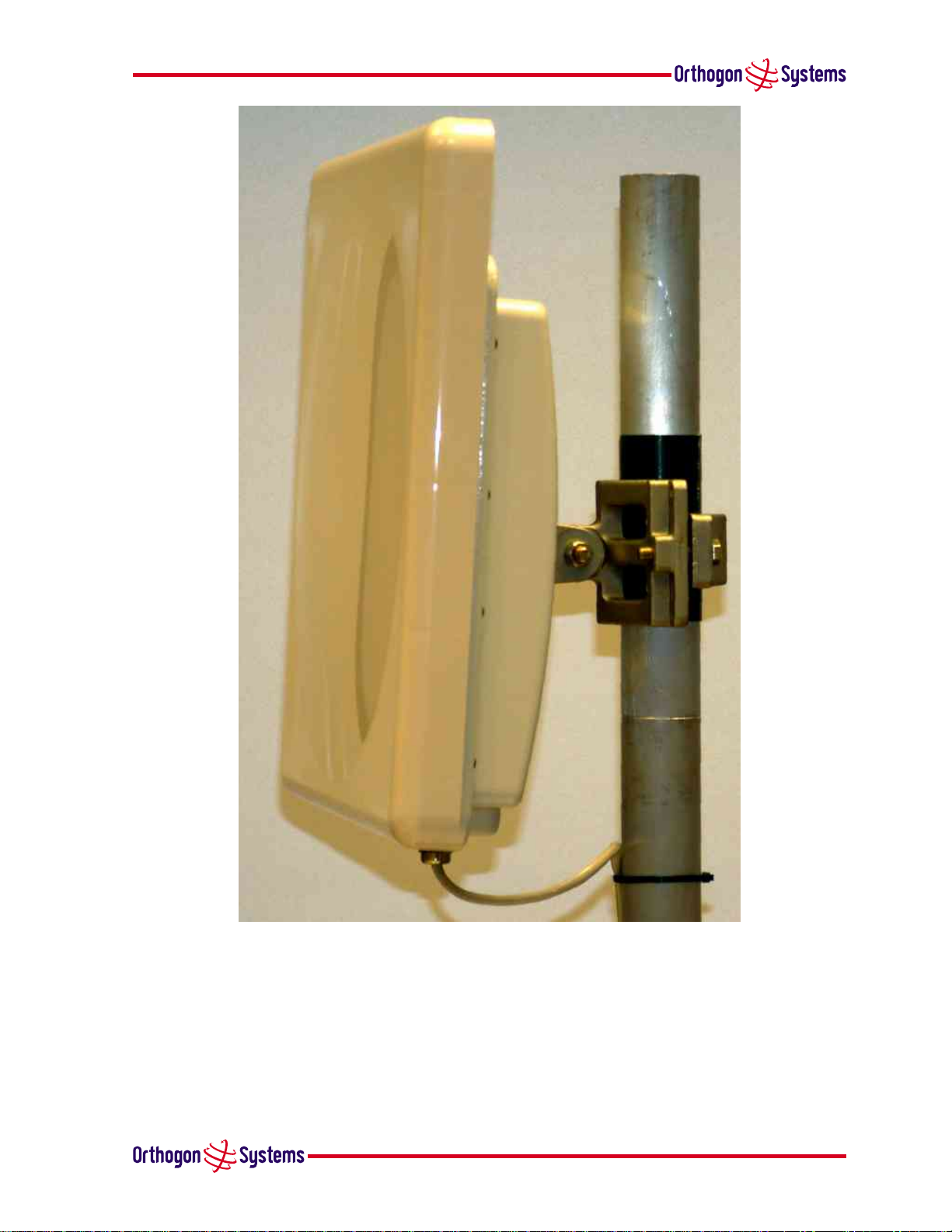
1.3.1 The Outdoor Unit (ODU)
The ODU is a self-contained unit. It houses both radio and networking electronics. Theunit is fed
by a single CAT 5 UTP cable. Power is fed to the unit via the brown/brown-white pair connected
to pins 7 and 8 of the RJ45 plugs and sockets employed. It should be noted that this powering
arrangement is not standard Power-over-Ethernet (POE). The OS-Gemini ODU should only be
deployed using the supplied OS-Gemini Indoor Unit (IDU).
1.3.2 The Indoor Unit (IDU)
The OS-Gemini IDU is a passive device used to inject the DC supply voltage into the cable connecting the IDU to the ODU. The IDU also houses status indicators driven from the ODU over the
blue/blue-white pair connected to pins 4 and 5 of the RJ45 plugs and sockets employed.
The front panel contains indicators showing the status of the power and Ethernet connections.
• the power indicator is illuminated when the IDU is receiving 48 voltsfrom the power adaptor.
• the Ethernet indicator illuminates whenthe ODU is powered; itflashes when there is Ethernet
activity.
The bottom of the IDU contains the Ethernet connection via RJ45 socket, the power connection,
an entry point for IDU-ODU cabling and the reset button.
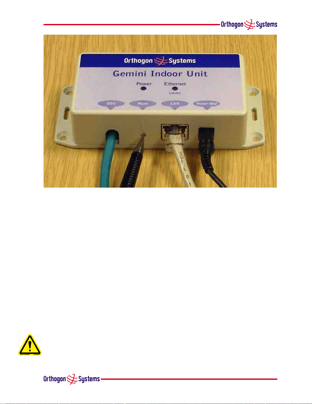
The IDU also houses a reset switch. This reset switch is used for various purposes identified in
table 1.
reset IP switch
6
1.3.3 Mains Power Adaptor
The mains poweradaptor is an in-line power supply which provides a 48Volt DC output to supply
power to the IDU / ODU
Caution Safety may be compromised if a different power supply is used instead of the one
supplied as part of the system.
Figure 2 OS-Gemini Outdoor Unit (ODU)
7
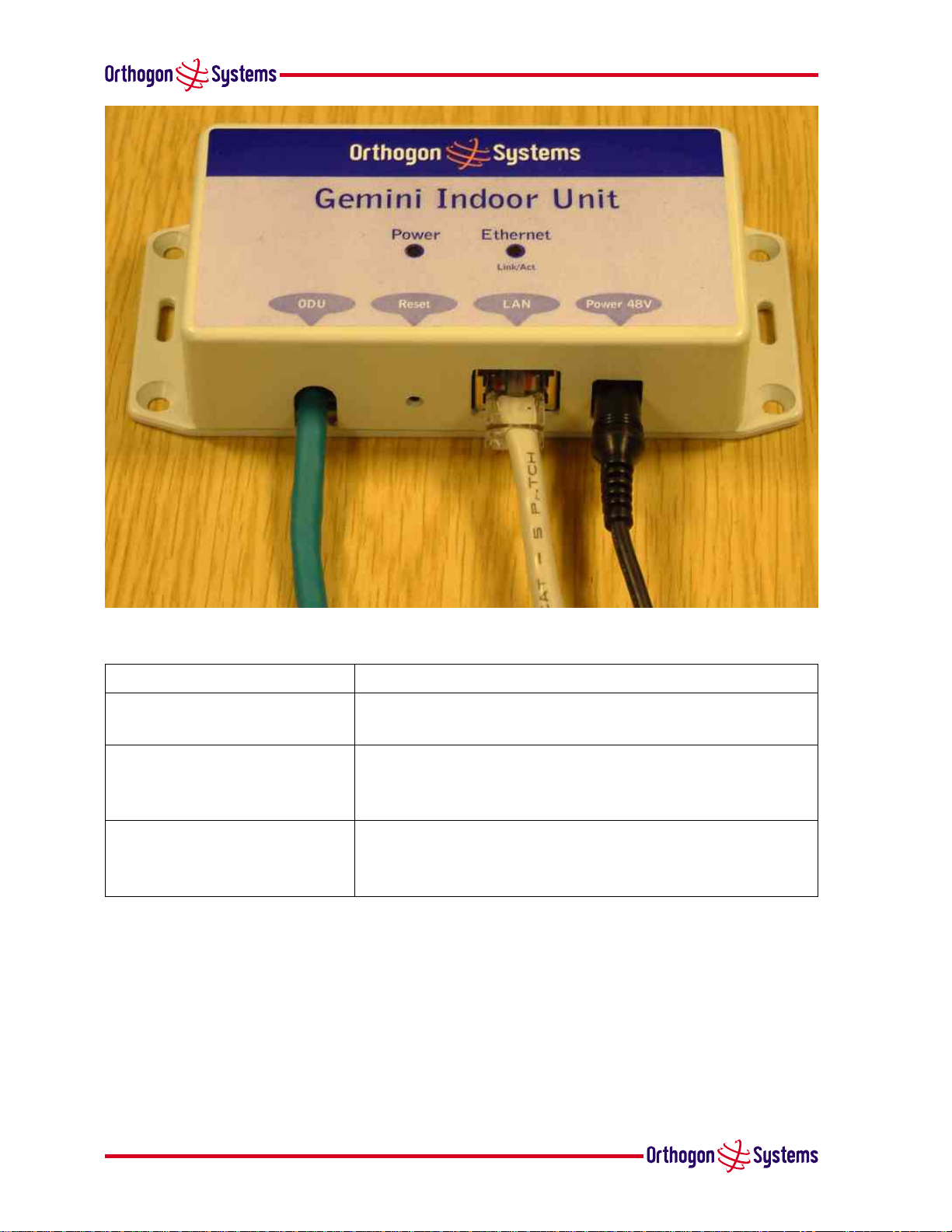
Figure 3 OS-Gemini Indoor Unit (IDU)
Reset Button Depression Action
Momentary This is the same as a power cycle. It simply restarts the
unit using the same configuration and software as before.
More than 10 secs This resets the configuration to factory defaults. All
parameters will need to be reentered including the web
page which will have returned to 10.10.10.10.
While connecting power for
more than 15 secs after power
is applied
1.3.4 Cables and Connectors
The cable used to connect the IDU to the ODU can be any standard CAT 5 type provided that it is
suitable for outdoor deployment. Orthogon Systems recommends that cables to the specification
below are used.
NEC/CEC: CMR(ETL) C(ETL) 75C SUN RES OIL RES II
8
This resets to factory defaults including to the initial
software load.
Table 1 Reset actions
Failure to use the recommended (or equivalent) standard of cable may invalidate the systems
safety certification.
The IDU/ODU cable may be unscreened (UTP) or screened (STP). However, unscreened cables reduce the system’s ability to cope with nearby lightening strikes. If lightening activity is common
in the area of deployment, the use of screened cable is highly recommended.
The connection between the IDU and users equipment can be made using any standard CAT5 UTP
patch cable. The RJ45 Ethernet connection is presented as a piece of network equipment. However as automatic MDI/MDI-X sensing and pair swapping is employed a crossed or non-crossed
Ethernet patch cable can be used for connection to another piece of networking equipment or
directly to end user equipment.
It should be noted that the IDU provides continuity between the screen on the ODU-IDU cable and
screen on the IDU-User equipment cable. If continuity of the screening is desired from the ODU
to the users equipment, CAT 5 STP cable and connectors should be used for the latter connection.
1.3.5 Surge Arrestor
The IDU does not provide lightning or surge suppression. Should lightning or surge suppression
be required a separate Ethernet surge suppressor should be used and appropriately earthed. Suitable surge suppressors can be sourced from your Orthogon Systems distributor or re-seller. The
ODU is protected through built-in surge suppression as standard.
Figure 4 OS-Gemini Reset Switch
9

1.3.6 Mounting Brackets
The OS-Gemini ODU is supplied with a mounting bracketsuitable for mounting the ODU to a pole
of 50mm to 75mm in diameter or to a flat surface. For more details on mounting see section 5
“Installation”
The bracket allows for adjustment in both azimuth and elevation. The bracket can be split,
allowingone half to mounted to the ODU and theother half to the pole or wallprior to installation.
This allows the installer to take the weight of the unit on a single mounting bolt while fitting the
retaining nut and washers.
Figure 5 OS-Gemini power adaptor
Pole Wall
Figure 6 ODU Mounting Configurations
10

The OS-Gemini IDU can either be desk or wall mounted. The preference is wall mounted with
the cables dressed to a skirting board or cable channel. Wall mounting is achieved by screwing
through the mounting lugs on either side of the unit.
1.3.7 Configuration and Management
Configuration and Management of the OS-Gemini is implemented using an inbuilt web server
hosting a number of Configuration and Management web pages. This approach allows Configuration and Management to be carried out on any standard web browsing technology. Connection
to the OS-Gemini is via the Ethernet connection carrying the bridge network traffic. Connection
to the unit is via a preset IP address. This address can be changed via the Network Interface Configuration web page. A full explanation of the available web pages and their use can be found in
section 6 “Web Page Reference”.
1.4 Warranty
Orthogon Systems offers a warranty covering a period of 1 year from the date of purchase by
the end customer. If the product is found to be defective during the warranty period, Orthogon
Systems Ltd. will repair or replace the product with the same or a similar model, which may
be a reconditioned unit, without charge for parts or labour. IN NO EVENT SHALL ORTHOGON
SYSTEMS BE LIABLE TO YOU OR ANY OTHER PARTY FOR ANY DIRECT, INDIRECT, GENERAL, SPECIAL, INCIDENTAL, CONSEQUENTIAL, EXEMPLARY OR OTHER DAMAGE RISING OUT OF THE USE
OR INABILITY TO USE THE PRODUCT (INCLUDING, WITHOUT LIMITATION, DAMAGESFORLOSS OF
BUSINESS PROFITS, BUSINESS INTERRUPTION, LOSS OF BUSINESS INFORMATION OR ANY OTHER
PECUNIARYLOSS, OR FROM ANY BREACHOFWARRANTY, EVEN IF ORTHOGONSYSTEMSLTD. HAS
BEEN ADVISED OF THE POSSIBILITY OF SUCH DAMAGES. (Some states do not allow the exclusion
or limitation of incidental or consequential damages, so the above exclusion or limitation may
not apply to you.) IN NO CASE SHALL ORTHOGON SYSTEMS’ LIABILITY EXCEED THE AMOUNT
YOU PAID FOR THE PRODUCT.
11
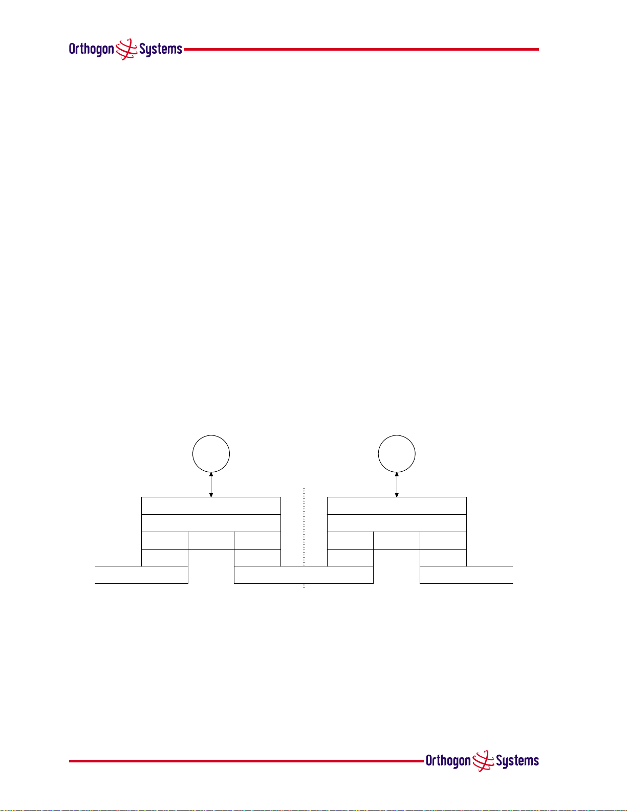
2 Product Architecture(MoreDetail About TheOS-Gemini)
Ethernet
PHY
DLC
Bridging
Network(IP)
Transport(TCP, UDP)
DLC
PHY
http
5GHz Wireless
PHY
DLC
Bridging
Network(IP)
Transport(TCP, UDP)
DLC
PHY
Ethernet
http
The OS-Gemini consists of an identical pair of units deployed one at each end of the link. The
radio link operates on a single frequencychannel using TimeDivisionDuplex (TDD). Oneunit is
deployed as a master and the other as a slave. The master unit takes responsibility for controlling
the link in both directions.
The non-Line-of-Sight (nLoS) aspects of the product are provided by multi-beam space time
coding, coupled with OFDMmodulation with a dispersion capability of 10 microseconds in both
directions.
The OS-Gemini has been developed to operate in license exempt frequency bands for example
the ETSI 5.8 GHz C band (5.725–5.875 GHz) and the USA 5 GHz ISM band (5.725–5.850GHz).
The OS-Gemini has been designed to coexist with other users of the band in an optimal fashion
using a combination of Transmit Power Control (TPC), Dynamic Frequency Selection (DFS) and
Antenna beam shape.
In order to maintain link availability, the product employs adaptive modulation techniques that
reduce the data rate in severe or adverse conditions.
The OS-Gemini operates as a standard IEEE 802.3 Ethernet bridge as defined in IEEE 802.1. The
OS-Gemini is implemented as a learning bridge. A learning bridge builds up a picture of which
addresses are connected to which port. This means that it will not re-transmit a packet if it knows
that the destination address is connected to the same port on which the bridge saw the packet.
Figure 7 illustrates the OS-Gemini layer diagram.
12
Figure 7 OS-Gemini Layer Diagram
The OS-Gemini functionality has been extended to encompass the IEEE 802.1q sub-specification
IEEE 802.1p. IEEE 802.1p allows the Ethernet packets to be extended by 8 bytes to include the
IEEE 802.1q VLAN Tag and VLAN Priority/ID with VLAN ID set to 0 and the packet priority set to
0-7. The OS-Gemini will forward all VLAN tagged packets regardless of the VLAN ID value.
Each unit in the link is manageable through an IP connection. Standard IP protocols are utilised
for all management functions e.g. HTTP, TFTP, etc. The OS-Gemini is fully software upgradeable. New software images are first downloaded from the Orthogon Systems support web site

(www.orthogonsystems.com/support/download) to a convenient platform. The image
is then uploaded to the ODU via the web management page described in section 6.3.3 “Software
Upgrade Pages”. The compressed image is first loaded into RAM and check summed. If the
compressed image transfer has completed successfully the image is decompressed and written to
Flash memory. On completion of this process the unit will re-boot using the newly downloaded
image. Should this process fail the unit will revert to a protected compressed image installed
during manufacturing to allow the unit to be recovered.
13

3 General Considerations
3.1 Frequency Planning
The OS-Gemini is capable of operating in the whole frequency range 5.725 to 5.875 GHz
(defined as the ETSI 5 GHz C band) but for the USA is optimised for the ISM band (5.725-
5.850GHz), utilising a 10MHz wide channel. Setting of the operating frequency channel is
automatic and is carried out by the built-in Dynamic Frequency Selection (DFS) functionality.
The user can configure the OS-Gemini to avoid using certain frequencies to prevent interference
to other users of the band and prevent operation in parts of the band containing interference. The
use of this functionality is described in detail in section 6.3.4 “DFS Pages”.
3.2 Distance
The OS-Gemini will operate at ranges from 100m to 40 km. Operationof the system will depend
on obstacles in the path between the units. Operation at 40km will require a Line of Sight
(LoS) path. Operation at 100m could be achieved with one unit totally obscured from the other
unit, but with the penalty of transmitting at higher power in a non-optimal direction, thereby
increasing interference in the band. This subject is covered in more detail in section 4.2 “Path
Loss Considerations
”.
3.3 Networking Information
The OS-Gemini operates as a transparent Ethernet bridge. Each unit requires an IP address.
This IP address is for management purposes only; it does not play any part in the operation on
the system. IP addresses are assigned during initial configuration as described in section 5.2
“Installation Procedure”.
3.4 Lightning Protection
The amount of lightning protection is dependant on regulatory requirements and the end user
requirements. The standard OS-Gemini ODU is fitted with surge limiting circuits and other features to minimise the risk of damage due to nearby lightning strikes. These standard features
may require some additional equipment to be configured as part of the system installation to be
fully effective. Orthogon Systems recommends the use of screened cable and surge arrestor to
protect connected equipment from nearby strikes.
Note: The OS-Gemini is not design to survive direct lightning strikes. For this reason
the unit should not be installed as the highest point in a localised area, unless
specific precautions are taken. See
section 9 “Lightning Protection”.
14

3.5 Electrical Requirements
The OS-Gemini is supplied with a variable input voltage in-line power supply unit. This unit is
supplied with mains cables suitable for the country of sale. The OS-Gemini requires one mains
supply outlet at each end of the link.
3.6 Training
Installation training courses can be purchased from Orthogon Systems. Self paced Computer
Aided Instruction (CAI) courses can be purchased and downloaded from the Orthogon Systems
website. Tailored courses can be supplied at your own premises or at Orthogon Systems HQ. See
http://www.orthogonsystems.com/training for more details.
15
 Loading...